

Page 1
X-378
7-CHANNEL COMPUTER
RADIO SYSTEM
INSTRUCTION MANUAL
FOR AIRPLANE,
HELICOPTER
AND
SAILPLANE
4682 JR X-378 • ALL 7/23/02 10:07 PM Page 1
Page 2

2
X-378 MANUAL Table of Contents
T ABLE OF CONTENTS
I. INTRODUCTION
Table of Contents 2
1. Using The Manual 4
2. Features 4
2.1 Transmitter 4
2.2 Receiver 4
2.3 Servo Features 5
3. Componenet Specifications
3.1 System Specifications 5
3.2 Transmitter Specifications 5
3.3 Servo Specifications 6
3.4 Receiver Specifications 6
3.5 Charger Specifications 6
3.6 Airborne Battery Pack 6
4. Battery Charging 7
4.1 Transmitter/Receiver 7
4.2 Charger 7
4.3 Advanced Digital Trims 8
II. AIRPLANE SECTION
1. Software Funtions
1.1 Control Identification and Location 9
1.2 Channel Assignment/Throttle ALT 9
A. Airplane Version Transmitter 9
B. Sailplane Mode 10
C. Heli Mode 10
1.3 Transmitter Rear 11
1.4 Control Stick Length Adjustment 12
1.5 Control Stick Tension Adjustment 12
1.6 Direct Servo Control 12
1.7 Neck Strap Attachment 13
1.8 Base Loaded Antenna 13
1.9 Frequency Notes/Aircraft Only Frequencies 13
2. Connections
2.1 Installation Requirements 14
2.2 Connections 14
3. Mode Input an Function 15
4. Alarm and Error Display 15
4.1 Battery Alarm and Display 15
4.2 Backup Error Display 15
5. System Mode Function 16
5.1 Normal Display 16
5.2 Direct Access Digital Trims 16
5.3 System Mode 17
5.4 Model Selection/Copy Select 18
5.5 Model Name Entry 20
5.6 Model Type Selection 21
5.7 Data Reset 22
5.8 Modulation Select 23
5.9 Data Transfer 24
5.10 Trim Step 25
5.11 Throttle Cut Switch 26
5.12 Wing Type Selection 27
5.13 Aux 2/Spoiler Channel Input Select 30
6. Function Mode
6.2 Servo Reversing 31
6.3 Dual-Rates 33
6.4 Exponential 35
6.5 Sub Trim 38
6.6 Travel Adjust 39
6.7 Elevator-toFlap Mixing 40
6.8 Aileron-to-Rudder Mixing 42
6.9 Mode Function 44
6.10 Snap Roll Function 46
6.11 Differential Aileron Mixing 48
6.12 Landing Attitude 50
6.13 Programmable Mixing 51
6.14 Fail Safe/Hold 55
6.15 Trainer System 59
6.16 Timer Function 62
7. Practical Applications 64
7.1 Programmable Mixing Options 64
8. Data Sheet 65
III. HELICOPTER
1. Transmitter Controls 66
1.1 Control Identification and Location 66
A. Helicopter Version Transmitter 66
1.2 Channel Assignment/Receiver
66
1.3 Transmitter Rear 68
1.4 Control Stick Length Adjustment 69
1.5 Control Stick Tension Adjustment 69
1.6 DSC Cord 69
1.7 Neck Strap Attachment 70
1.8 Base Loaded Antenna 70
1.9 Frequency Notes/Aircraft Only Frequencies 70
2. Connections 71
2.1 Installation Requirements 71
2.2 Connections 71
3. Key Input and Display 72
4. Alarm and Error Display 72
4.1 Battery Alarm and Display 72
4.2 Backup Error Display 72
5. System Mode 73
5.1 Normal Display 73
5.2 System Mode 73
5.3 Function Mode 74
5.4 Model Selection/Model Copy Select 75
5.5 Model Name Entry 77
5.6 Model Type Selection 78
5.7 Data Rest 79
5.8 Modulation Select 80
5.9 Data Transfer 81
5.10 Trim Step 84
5.11 Throttle Cut Switch Activation 85
5.12 Aux/Gear Function Select 86
5.13 Swashplate Type 87
6. Function Mode 88
6.1 Function Mode 88
6.2 Servo Reversing 89
6.3 Dual-Rates 90
6.4 Exponential 92
6.5 Sub Trim 93
6.6 Travel Adjust 94
6.7 CCPM Swashplate Mixing 95
6.8 Throttle Hold 97
6.9 Throttle Curve 98
6.10 Pitch Curves 101
6.11 Inverted Switch 103
4682 JR X-378 • ALL 7/23/02 10:07 PM Page 2
Page 3

3
X-378 MANUAL Table of Contents
T ABLE OF CONTENTS
6.12 Revolution Mixing 104
6.13 Gyro Gain Function 106
6.14 Programmable Mixing 110
6.15 PCM Fail-Safe/Hold Function 114
6.16 Trainer System 117
6.17 Timer Function 119
7. Data Sheet 121
IV. SAILPLANE
1. Transmitter Controls
1.1 Control Identification and Location 122
A. Glider Version Tx 122
B. Airplane Mode 123
C. Heli Mode 123
1.2 Channel Assignment/Throttle ALT 123
1.3 Transmitter Rear 124
1.4 Control Stick Length Adjustment 125
1.5 Control Stick Tension Adjustment 125
1.6 DSC Cord 125
1.7 Neck Strap Adjustment 126
1.8 Base Loaded Antenna 126
1.9 Frequency Notes/Aircraft Only Frequencies 126
2. Connections
2.1 Installation Requirements 127
2.2 Connections 127
3. Key Input and Display 128
4. Alarm and Error Display 128
4.1 Battery Alarm and Display 128
4.2 Back-Up Error Display 128
5. System Mode 128
5.1 Normal Display 128
5.2 Model Setup Mode 129
5.3 Function Mode 130
5.4 Model Selection/Model Copy Select 131
5.5 Model Name Entry 133
5.6 Model Type Selection 134
5.7 Data Rest 135
5.8 Modulation Select 136
5.9 Data Transfer Function 137
5.10 Trim Step 140
5.11 V-Tail/Dual Flap Wing Mixing 141
5.12 Flap Switch Select Function 143
6. Function Mode
6.1 Function Mode 144
6.2 Servo Reversing 145
6.3 Dual Rates 146
6.4 Exponential 148
6.5 Sub Trim 149
6.6 Travel Adjust 150
6.7 Elevator-to-Flap Mixing 151
6.8 Aileron-to-Flap Mixing 153
6.9 Differential Aileron Mixing 155
6.10 Flap to Elevator Mixing 156
6.11 Flap-to-Aileron Mixing 159
6.12 Aileron-to-Rudder Mixing 162
6.13 Crow/Camber Mixing 164
6.14 Dual-Flap Trim 166
6.15 Programmable Mixing 1-6 167
6.16 Fail-Safe/Hold Function (PCM Only) 171
6.17 Trainer System 175
6.18 Timer Function 177
7. Practical Applications 179
7.1 X-378 Program 179
8. Data Sheets 184
V. IMPORTANT INFORMATION
1. Servo Precautions 185
2. General Notes 185
3. Federal Aviation Administration 186
4. Daily Flight Checks 186
5. Frequency Chart 187
6. Warranty Information 188
4682 JR X-378 • ALL 7/23/02 10:07 PM Page 3
Page 4
4
X-378 MANUAL Introduction
In the beginning of this manual you will find the
specifications for the radio and its various
accessories. In addition, guidelines for the initial
installation of the accessories have been included,
as well as instructions for setting all the functions
and programs of the X-378 to suit your personal
preferences. These features are discussed in the
same order that they will appear on your radio,
as you will see on the accompanying charts. An
explanation of the use and purpose of each feature
is provided, followed by a labeled illustration of its
respective LCD display.
In addition, a step-by-step example clarify the setup
procedure of the feature. Practical applications for
many of the radio’s features enable you to see their
true purpose and additional possibilities. A blank
data sheet has been included at the end of each
section. Once all data has been input for a
particular model, it is highly recommended that you
record it on a copy of the sheet provided. If you
should experience memory loss or battery failure or
want to make changes to the current settings, this
step will save you a great deal of time. Following
the data sheet, you will find information on
precautionary measures and general guidelines for
safe use of your new equipment.
Use of the Instructions with the Radio
While the X-378 has a dedicated or single-use
switch layout, it may be used for multiple model
types. Templates have been provided in this manual
that explain the different switch assignments when
using the transmitter with the various air, heli and
sailplane software.
The computer designed, ergonomically styled
transmitter case ensures a good, comfortable fit in
your hands. The ultra-precision control sticks offer
adjustable spring tensions and length. The throttle
stick offers a ratchet in Airplane configuration for
smooth travel. 8-model memory storage allows
programming of all characteristics of eight separate
helicopters, airplane or gliders; you can program
more than one setup for a single aircraft, allowing
you to instantly change the flight characteristics.
A five-year lithium backup battery prevents loss of
memory in the event that the battery discharges
completely or is removed.
Features include automatic fail-safe "set" and
information update in PCM mode when fail-safe is
used. A programmable trainer function allows the
student to practice individual channels separately.
Direct Servo Control (DSC) permits operation of
all the controls and servos without generating a
radio signal.
CHAPTER 1: USING THIS MANUAL • Introduction
CHAPTER 2: FEA TURES
USING THIS MANUAL
X-378 TRANSMITTER
1
2.1
NER-700 (FM Systems)
The R700’s is a high-performance FM or singleconversion receiver with 10KHz super narrow band
ABC&W circuitry.
A narrow band ceramic filter for high-signal
selectivity assists in rejecting cross modulations
from other common radio frequencies-e.g., R/C
transmitters, local paging systems. This receiver
features Direct Servo Control (DSC) for control of
surfaces without radio frequency output.
The receiver has low current consumption.
The R700's Slimline design allows it to fit into most
model applications.
R700 RECIEVER
2.2
4682 JR X-378 • ALL 7/23/02 10:07 PM Page 4
Page 5
5
X-378 MANUAL Introduction
CHAPTER 3: COMPONENT SPECIFICA TIONS
537 Servo
• Wide spaced ball bearing for precise movement
of your aircraft control outputs
• A zero deadband amplifier insures accurate
neutral centering
• Low current drain
• Indirect drive feedback potentiometer gives
additional protection from vibration
• 3-pole ferrite cored motor
S537 BALL BEARING SERVOS
2.3
SYSTEM SPECIFICATIONS
3.1
SYSTEM NAME X-378A X-378H
TRANSMITTER BODY NET-K227FS Net-K227HS
TRANSMITTER RF MODULE NET-J72P NET-J72P
RECEIVER R700 (FM) R700 (FM)
CHARGER NEC-221 NEC-222
AIRBORNE BATTERY 600mah 1100mah
SERVOS NES-537X4 NES-537X5
ACCESSORIES Standard Switch Standard Switch
12" Aileron Extension 12" Aileron Extension
Charge Jack Charge Jack
Servo Accys Servo Accys
Hex Wrench Hex Wrench
Instruction Manual Instruction Manual
TYPE AIRPLANE HELICOPTER
TRANSMITTER SPECIFICATIONS
3.2
MODEL NUMBER NET-K227FS Net-K227HS
ENCODER 7–channel computer system 7–channel computer system
RF MODULE 72MHz 72MHz
MODULATION PCM (z or s) or PPM PCM (z or s) or PPM
OUTPUT POWER Approximately 750mw Approximately 750mw
CURRENT DRAIN 200mA (70mA with DSC) 200mA (70mA with DSC)
POWER SOURCE 1.2Vx Ni-Cd (9.6V) 600mAh 1.2Vx Ni-Cd (9.6V) 600mAh
OUTPUT PULSE 1000–2000 (1500 Neutral) 1000–2000 (1500 Neutral)
TYPE AIRPLANE HELICOPTER
4682 JR X-378 • ALL 7/23/02 10:07 PM Page 5
Page 6
6
X-378 MANUAL Introduction
SERVO SPECIFICATIONS
3.3
TORQUE (ounce inch) 43 oz/in
SPEED (sec/60°) .2 5 6 0 °
WEIGHT 1.58
SIZE (in) (W x L x H) 1.52 x 0.73 x 1.32
BB Single
MOTOR 3-Pole Ferrite
TYPE 537
RECEIVER SPECIFICATIONS
3.4
MODEL NUMBER R700
TYPE 7 Channel / FM-ABC&W / Micro
FREQUENCY 72MHz
SENSITIVITY (Microseconds) 5 uS minimum
SELECTIVELY 8KHz/ 5 dB
WEIGHT (oz) 1.5
RECEIVER ANTENNA 39“ for all aircraft frequencies
TYPE FM
CHARGER SPECIFICATIONS
3.5
MODEL NUMBER NEC-221 NEC-222
INPUT VOLTAGE AC 100–120V AC 100–120V
OUTPUT CURRENT 50mAh TX/50mAh RX 50mAh TX/120mAh RX
CHARGING TIME 15 Hours 15 Hours
TYPE AIRCRAFT HELICOPTER
AIRBORNE BATTERY PACK
3.6
MODEL NUMBER B600 B1000
VOLT AGE 4. 8 V 4. 8 V
SIZE (in) (W x L x H) 2.24 x 0.59 x 2.05 2.24 x 0.63 x 1.70
WEIGHT (oz) 3.3 4.9
TYPE AIRCRAFT HELICOPTER
4682 JR X-378 • ALL 7/23/02 10:07 PM Page 6
Page 7
7
X-378 MANUAL Introduction
Note:
It is imperative that you fully charge
both the transmitter and the receiver battery
packs prior to each flight. To do so, leave
the charger and batteries hooked up overnight
(16 hours). The first charge should be
approximately 20–24 hours in order to fully
charge both battery packs to peak capacity.
The charger supplied with this system is
designed to recharge your batteries at a rate
of 5mAh for the transmitter and 50mAh for
the receiver battery pack.
Transmitter Only
The center pin on all JR Remote Control Systems is
negative. Therefore, the center pin on all JR chargers
is negative, not positive. This is different from many
other manufacturers' chargers and radio systems.
Beware of improper connections based on "colorcoded" wire leads, as they do not apply in this
instance. You must make sure that the center pin of
your JR transmitter is always connected to the
negative voltage for correct polarity hookup.
Important: Please note that the charging
polarity of the transmitter and receiver
are different.
CHAPTER 4: BA TTER Y CHARGING
TRANSMITTER/RECEIVER
4.1
The pilot lamps should always be on during the
charging operation. If not, check to make sure that
both the transmitter and receiver are switched off.
Do not use the charger for equipment other than JR.
The charging plug polarity may not be the same.
Equipment damage can result.
Do not use other manufacturers' after-market
accessories that plug into the transmitter's charging
jack. If you do, any damage that results will not be
covered by warranty. If you are unsure of compatabily
issues with your radio, seek expert advice before
doing anything to avoid possible damage.
During the charging operation, the charger's
temperature is slightly elevated. This is normal.
Also, note that the voltage shown on the charger is
higher than the battery in use. This voltage cannot
be measured with a voltmeter. Only current can
be measured with any accuracy using this type
of charger.
Be sure to use the proper charger (120mAh)
when using battery packs of 1000mAh or larger for
your receivers.
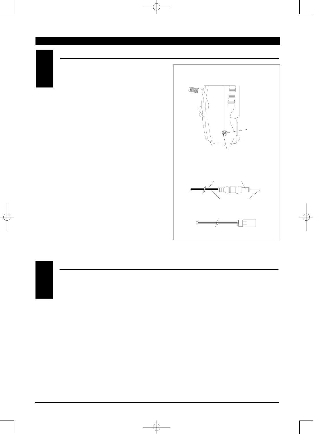
CHARGER
4.2
CENTER
PIN IS
NEGATIVE
OUTSIDE IS POSITIVE
RIGHT SIDE OF TRANSMITTER
CHARGER PIGTAIL FOR RECEIVER
CHARGER PIGTAIL FOR TRANSMITTER
BLACK TO POSITIVE
RED TO NEGATIVE
RED–POSITIVE / BROWN–NEGATIVE / ORANGE–SIGNAL
4682 JR X-378 • ALL 7/23/02 10:07 PM Page 7
Page 8
Your new X-378 system employs four digital trim
levers for unmatched precision and adjustability.
By using the Trim Step function located in the
System mode, the movement of the ADT trims
can be fine tuned as needed to match your
specific application.
The ADT feature is also designed to automatically
save the determined trim values for each model.
When the X-378 is changed between models in the
Model Select function, the digital trim values will
automatically stay with each model, eliminating
the need for a separate trim memory function.
The X-378's digital trims also feature the Direct
Access display function. While at the Normal
display screen, if a trim lever is moved, the screen
will automatically change to display the numeric
value, as well as the graphic position for the trim
being adjusted.
The X-378's digital trims also feature 2-speed
scrolling . When a substantial amount of trim is
required, holding the trim in the desired position
will activate the dual speed scrolling function.
The X-378's Aileron, Elevator, and Rudder trim
levers (also throttle in sailplane mode) feature
an audible center trim beep. This is helpful in
determining the trim levers center position
during flight.
Please also note that unlike conventional
mechanical trim levers, when the X-378 transmitter
is in the off position, no changes can be made to
the trim values during transportation.
The X-378 also features a revolutionary One-Touch
Digital Throttle Trim lever. While in Air or Heli
modes, the X-378 will remember the maximum high
Throttle Trim position (usually idle) set from the
previous flight. At the end of the flight, move the
Throttle Trim to the full low (engine off) position.
For the next flight, by simply pressing the Digital
Throttle Trim up once, the throttle trim value will
automatically move to the position from the
previous flight. Trim value changes can then be
made by moving the throttle trim lever as needed.
The Direct Access Digital Trim function will display
the throttle trim value numerically and also
graphically on the screen automatically each time
the Throttle Trim is moved
This feature is very helpful as once you have set
the correct throttle trim value for a proper idle, the
X-378 will allow the Trim lever to be set back to this
position for each flight, eliminating the need to set
the exact throttle trim value for each flight.
Note: When the X-378 is in the glider
(sailplane) model type, the Digital Throttle
Trim works as a conventional trim lever, which
is the most desirable method in this mode.
ADVANCED DIGITAL TRIMS
4.3
One Touch Digital Throttle Trim Lever (Air and Heli Modes only)
8
4682 JR X-378 • ALL 7/23/02 10:07 PM Page 8
Page 9
9
X-378 MANUAL Airplane
SECTION II • CHAPTER 1: SOFTWARE FUNCTIONS Airplane
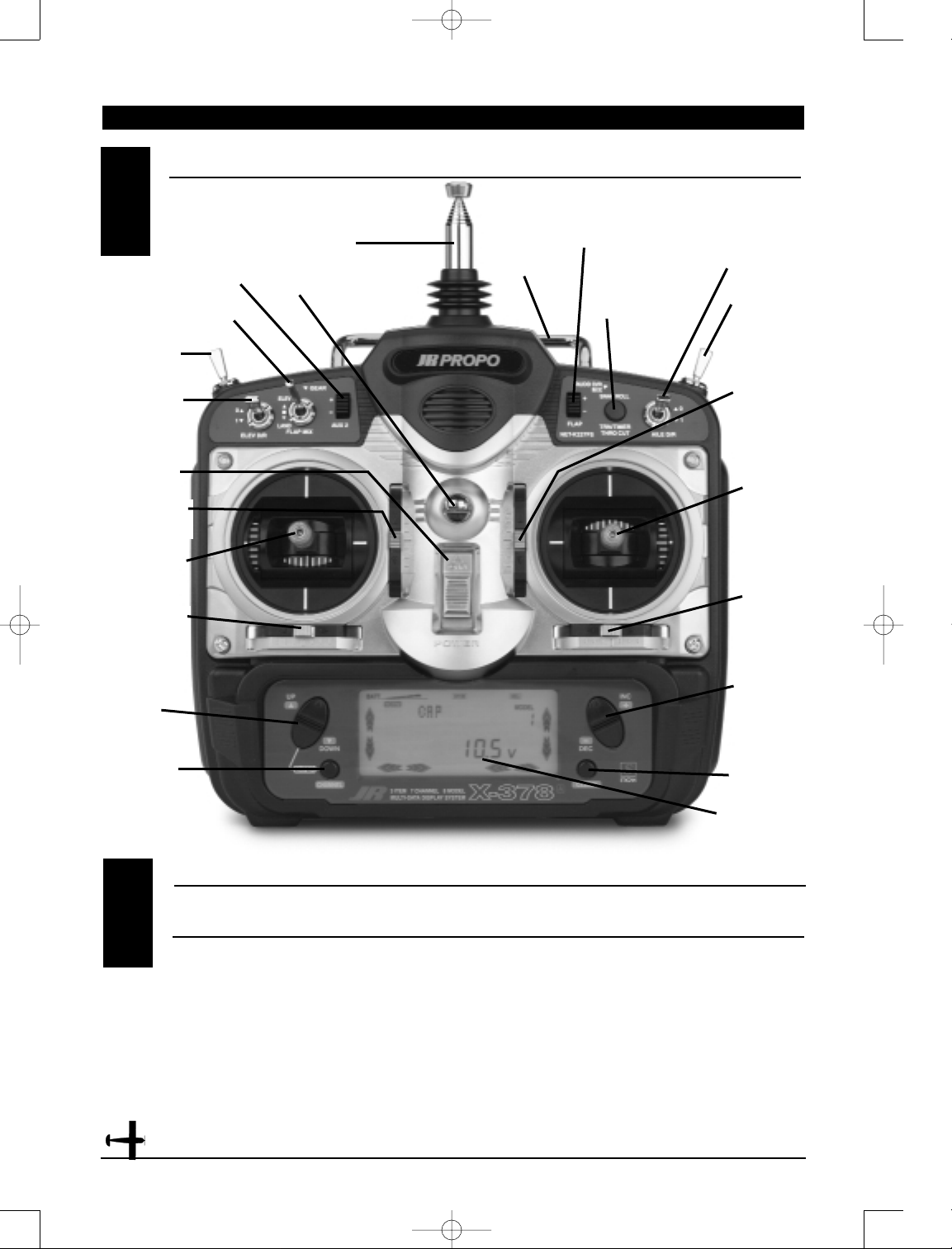
CONTROL IDENTIFICA TION AND LOCA TION
1.1
CHANNEL ASSIGNMENT/THROTTLE AL T
1.2
Channel TX Function Airplane Function
1 THRO Throttle Channel
2 AILE Aileron Channel
3 ELEV Elevator Channel
4 RUDD Rudder Channel
5 GEAR Gear Channel
6 AUX 1 Auxiliary 1 Channel
(Flap)
7 AUX 2 Auxiliary 2 Channel
(Spoiler)
Throttle ALT
The Throttle ALT function makes the throttle stick
trim active only when the throttle stick is at less
than half throttle. This gives easy, accurate idle
adjustments without affecting the high throttle
position.
CHANNEL ASSIGNMENT
Rudder/Throttle
Control Stick
Digital Rudder
Trim Lever
Digital
Aileron
Trim Lever
Up/Down
Scroll
Buttons
Channel Key
On/Off
Switch
Gear Switch
Flap Mix Switch
Antenna
Carrying
Handle
Flap
Lever
Snap Roll/Timer
Trainer/Button
Throttle Cut
Aileron D/R
Switch
Rudder DR
Switch
Digital
Elevator
Trim Lever
Aileron/
Elevator
Control
Stick
Increase/
Decrease
Programming
Buttons
Clear Key
LCD Display
Neck Strap Eyelet
Elevator DR
Switch
Digital Throttle
Trim Lever
AUX 2
Lever
4682 JR X-378 • ALL 7/23/02 10:07 PM Page 9
Page 10
10
X-378 MANUAL Airplane
CHAPTER 1: SOFTWARE FUNCTIONS Airplane
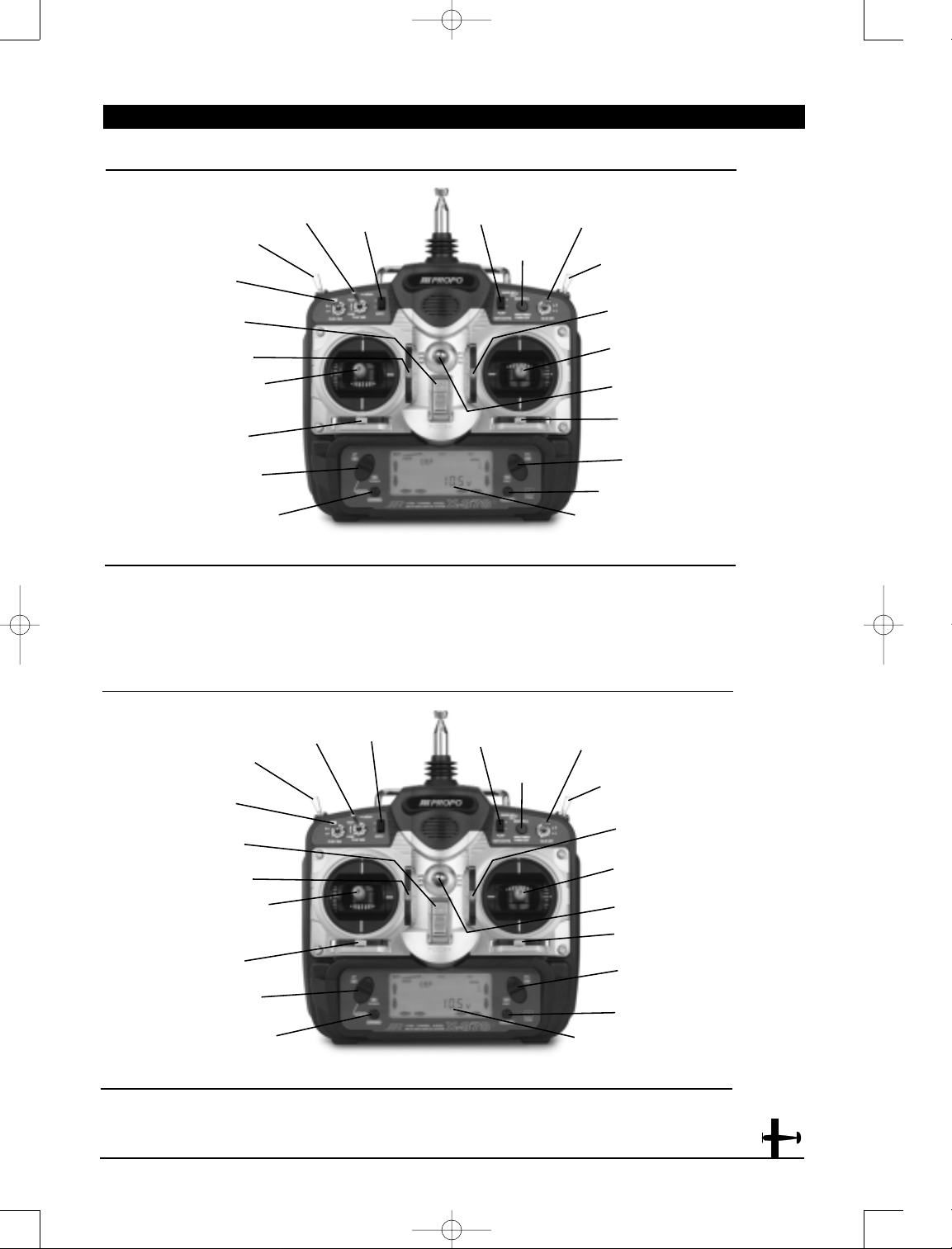
Airplane Version Transmitter—Sailplane Mode
1. THRO Throttle Channel
2. AILE Left Aileron Channel
3. ELEV Elevator Channel
4. RUDD Rudder Channel
5. GEAR Gear Channel
(Right Aileron Channel–AILE 2)
6. AUX 1 Auxiliary 1 Channel
(Left Flap Channel for Dual Flaps)
7. AUX 2 Auxiliary 2 Channel
(Right Flap Channel for Dual Flaps)
CHANNEL ASSIGNMENT
1. THRO Throttle Channel
2. AILE Aileron Channel
3. ELEV Elevator Channel
4. RUDD Rudder Channel
5. GEAR Gear Channel
6. AUX 1 Auxiliarty 1 Channel (Pitch)
7. AUX 2 Auxiliary 2 Channel
(Gyro Sensitivity)
Airplane Version Transmitter-Heli Mode
CHANNEL ASSIGNMENT
Spoiler/Rudder
Stick
Digital Rudder
Trim Lever
Up/Down
Scroll Buttons
Channel Key
On/Off
Switch
Crow Switch
Flap Mixing
Switch
Oval Flap Aileron
Trim Lever
Timer/Trainer
Button
Aileron D/R
Switch
Rudder DR
Switch
Digital Elevator
Trim Lever
Aileron/Elevator
Control Stick
Increase/Decrease
Programming Buttons
Clear Key
LCD Display
Elevator DR
Switch
Digital Spoiler
Trim Lever
Flapperon
Flap Trim
Lever
Throttle/Rudder
Stick
Digital Rudder
Trim Lever
Digital Aileron
Trim Lever
Up/Down
Scroll Buttons
Channel Key
On/Off
Switch
Gear Switch
Flight Mode
Switch
Hover Throttle
Lever
Timer/Trainer
Button
Throttle Cut
Button
Rudder DR
Switch
Digital Elevator
Trim Lever
Aileron/Elevator
Control Stick
Increase/Decrease
Programming Buttons
Clear Key
Neck Strap Eyelet
LCD Display
Elevator DR
Switch
Digital Throttle
Trim Lever
Digital Aileron
Trim Lever
Neck Strap Eyelet
Hover Pitch
Lever
4682 JR X-378 • ALL 7/23/02 10:07 PM Page 10
Page 11
11
X-378 MANUAL Airplane
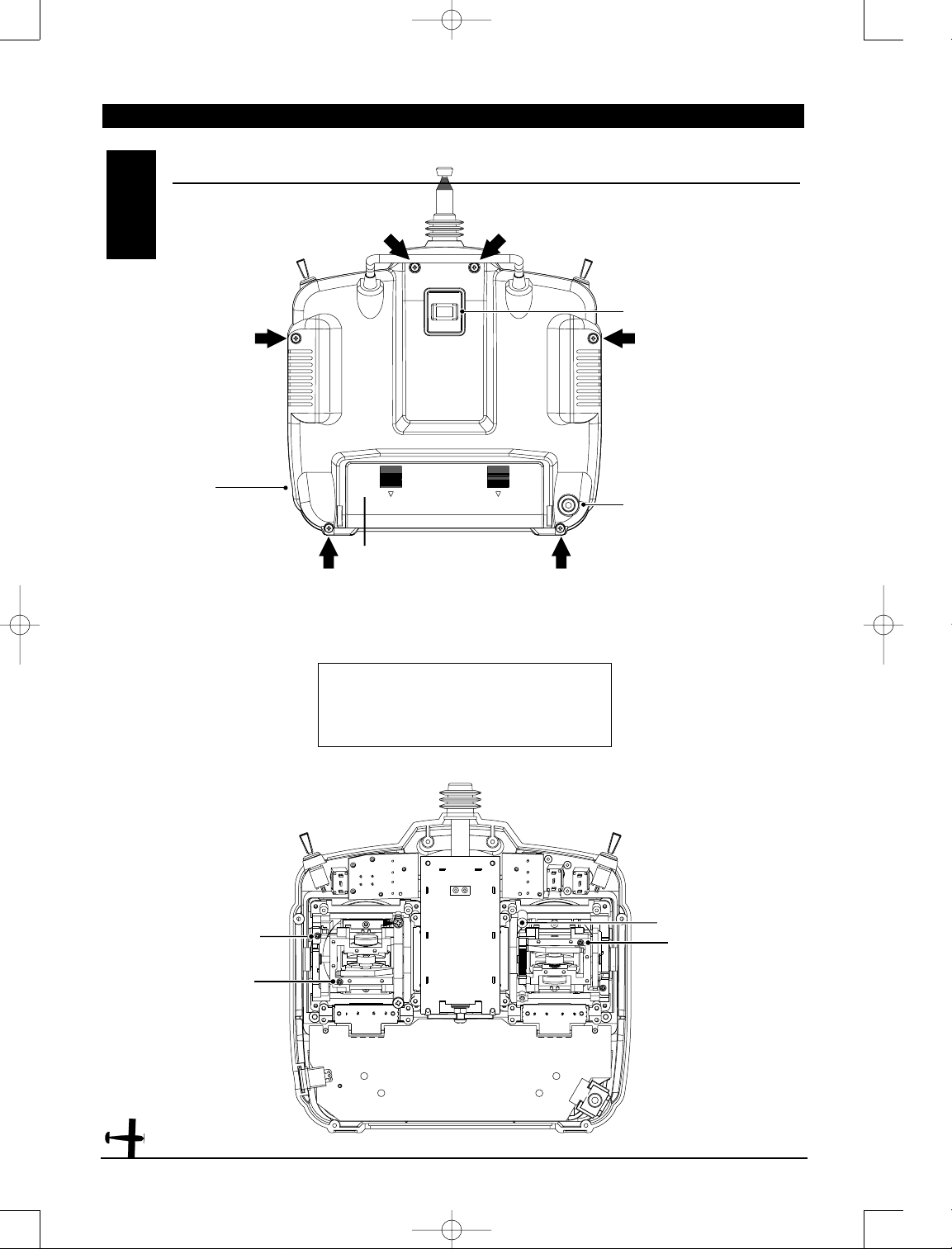
TRANSMITTER CRYSTAL
DSC/TRAINER JACK
CHARGING JACK
FOR Ni-Cd BATTERY
ONLY (8N-600)
BATTERY COVER (REMOVED)
CAUTION: THE BATTERY
CONNECTOR IS KEYED SO THAT IT
CAN ONLY BE PLUGGED IN ONE
DIRECTION. DO NOT FORCE.
TRANSMITTER REAR
1.3
ELEVATOR TENSION SCREW
RUDDER TENSION SCREW
THROTTLE TENSION SCREW
AILERON TENSION SCREW
Transmitter Crystal Replacement Notice
The Federal Communications Commission (FFC) requires that
changes in transmitter frequency must be performed only by an
authorized service technician (Horizon Service Center). Any
transmitter frequency change made by non-certified technician
may result in a violation of the FCC rules.
CHAPTER 1: SOFTWARE FUNCTIONS Airplane
4682 JR X-378 • ALL 7/23/02 10:07 PM Page 11
Page 12
12
X-378 MANUAL Airplane
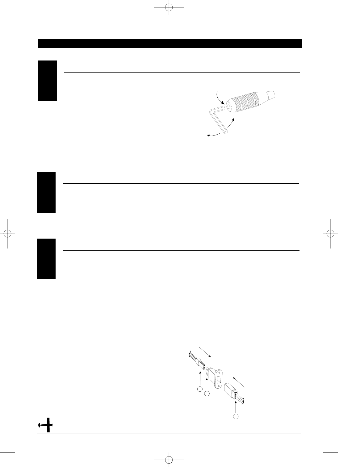
DIRECT SERVO CONTROL (DSC)1.6
CONTROL STICK LENGTH ADJUSTMENT1.4
To adjust the stick length, use the 2mm Allen wrench
(supplied with your X-378 transmitter) to unlock the
set screw. Turn the wrench counterclockwise to
loosen the screw. Then, turn the stick clockwise to
shorten or counterclockwise to lengthen. After the
control stick length has been adjusted to suit your
flying style, tighten the 2mm set screw. If you desire
longer sticks, JR offers a thicker stick (JRPA047) that
is approximately one inch longer than the standard
stick. This stick, crafted from bar stock aluminum, is
available at your local JR dealer.
For proper DSC hook-up and operation:
1. Leave the transmitter power switch in the Off
position. The transmitter will not transmit any radio
frequency (RF) in this position.
2. Plug the (supplied) DSC cord into the DSC port
in the rear of the transmitter.
3. The encoder section of the transmitter will now
be operational and the LCD display will be lit.
4. Plug the other end of the DSC Cord into the receiver
charge receptacle. Turn the switch harness to the On
position.
Note: When you install the charging jack, be
sure to hook the charging jack receptacle
securely into the switch harness charge cord.
Why you should use the DSC function:
1. The DSC enables you to check the control
surfaces of your aircraft without drawing the fully
operational 200mAh from your transmitter
battery pack. Instead, you will only draw 70mAh
when using the DSC function.
2. The DSC function allows you to make final
adjustments to your airplane without transmitting
any radio signals. Therefore, if another pilot is flying
on your frequency, you can still adjust your aircraft
and not interfere with the other pilot’s aircraft.
Note: Under no circumstances should you
attempt to fly your aircraft with the DSC cord
plugged in! This function is for benchchecking your airplane only.
A—Charge Cord/DSC Receptacle
B—Switch Harness Lead
C—Charger/DCS Cord
CHAPTER 1: SOFTWARE FUNCTIONS • Airplane
CONTROL STICK TENSION ADJUSTMENT1.5
Remove the Ni-Cd battery and six transmitter back
screws as shown on the previous page. Remove the
transmitter back, being careful not to cause damage
to any components.
Adjust each screw for desired tension (counterclockwise to loosen stick feel; clockwise to tighten
stick feel). When adjusting the throttle ratchet
tension, make sure that the adjusting screw does not
touch the PC board after adjustment is complete.
4682 JR X-378 • ALL 7/23/02 10:07 PM Page 12
SET SCREW
LOOSEN
TIGHTEN
B
A
C
Page 13
13
X-378 MANUAL Airplane
CHAPTER 1: SOFTWARE FUNCTIONS • Airplane
NECK STRAP A TTACHMENT1.7
An eyelet is provided on the face of the X-378
transmitter that allows you to connect a Neck Strap
(JRPA023). This hook has been positioned so that
your transmitter has the best possible balance when
you use the neck strap.
Note: Double-check to ensure that the neck
strap is securely fastened to the transmitter.
BASE LOADED ANTENNA
FREQUENCY NOTES/AIRCRAFT ONLY FREQUENCIES
1.8
An optional base-loaded antenna is available for use
with the X-378 transmitter. It is considerably shorter
than the standard antenna. However, the base
loaded antenna cannot be collapsed for storage in
the side of the transmitter. You must also use an
adaptor (JRPA156) to attach the antenna to your
X-378. The Base Loaded Antenna (JRPA155) is made
of a flexible coil and is covered with a soft plastic
material. Your range will not be affected when using
the base loaded antenna.
1.9
The X-378 transmitter employs a plug-in crystal for
transmitter that is glued in place at the time of
shipment. Per FCC regulation, the transmitter crystal
should only be changed by a certified technician.
Changing of the transmitter crystal by a nonauthorized technician could result in a violation
of FCC rules.
The X-378 can transmit in either Pulse Code
Modulation (PCM) or Pulse Position Modulation
(PPM, commonly referred to as FM).
Be certain to observe the following guidelines:
1. Do not operate your transmitter when another
transmitter is using the same frequency, regardless
of whether the second transmitter is PCM, PPM (FM)
or AM. You can never operate two transmitters on
the same frequency simultaneously without causing
interference to both receivers and crashing both
aircraft.
2. For operation of your X-378 with additional
receivers, you should refer to the receiver
compatibility chart. The chart is located in the
Modulation Selection Section of this manual.
Aircraft-Only Frequencies
JR Transmitters and receivers are available in 72MHz
frequencies in the United States for use with model
aircraft. Employing 72MHz frequencies does not
require a special operator’s license from the Federal
Communications Commission (FCC).
* A chart for all available frequencies is located on
page 185 of this manual.
4682 JR X-378 • ALL 7/23/02 10:07 PM Page 13
Page 14
14
X-378 MANUAL Airplane
CHAPTER 2: CONNECTIONS • Airplane
It is extremely important that your radio system be
correctly installed in your model. Here are a few
suggestions on the installation of your JR equipment:
1. Wrap the receiver in protective foam rubber that
is no less than 3/8 inch thick. Secure the foam to
the receiver with #64 rubber bands. This protects
the receiver in the event of a crash or a very hard
landing.
2. The servos should be mounted using rubber
grommets and brass bushings to isolate them from
vibration. Do not over-tighten the mounting screws;
this will negate the vibration absorption effect of the
rubber grommets. The following
diagram will assist you in
properly mounting
your servo.
The brass bushings are pushed from the bottom up
in the rubber grommets. When the servo screw is
tightened securely, it provides the proper security as
well as the proper vibration isolation for your servo.
3. The servos must be able to move freely over their
entire range of travel. Make sure that the control
linkages do not bind or impede the movement of any
of the servos.
4. Mount all switches away from the engine exhaust
and away from any high vibration areas. Make sure
the switch operates freely and is able to operate over
its full travel.
5. Mount the receiver antenna firmly to the airplane
to ensure that it will not become entangled in the
propeller or control surfaces.
INST ALLATION REQUIREMENTS
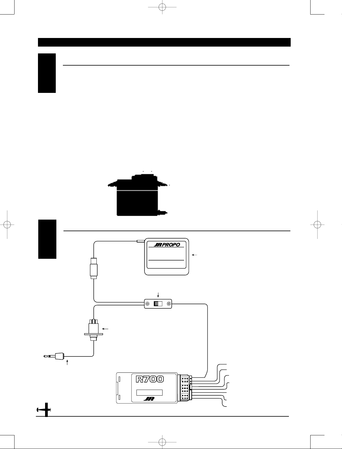
CONNECTIONS2.2
2.1
4N600
4.8V 600mAh
JAPAN REMOTE CONTROL CO., LTD.
®
ON
OFF
GEAR
7 CH 72MHz FM SLIMLINE
RECEIVER
ABC&W INTERFERENCE
PROTECTION SYSTEM
BATT
RUDD
ELEV
AILE
THRO
AUX1
RECEIVER BATTERY 4N-600
DELUXE SWITCH HARNESS
(JRPA0001)
CHARGECORD OR
D.S.C. RECEPTACLE
(JRPS024)
CHARGECORD OR D.S.C.
D.S.C.-(JRPA132)
CHARGER-(JRPC221)
R700 RECEIVER
AUXILIARY 2
BATTERY
GEAR
RUDDER
ELEVATOR
AUXILIARY 1
AILERON
THROTTLE
4682 JR X-378 • ALL 7/23/02 10:07 PM Page 14
Page 15
15
X-378 MANUAL Airplane
CHAPTER 3: INPUT MODE AND FUNCTION • Airplane
BA TTERY ALARM AND DISPLAY
CHAPTER 4: ALARM AND ERROR DISPLA Y • Airplane
4.1
When the transmitter voltage drops below 9.0 volts
DC, the display flashes “BATT” and an alarm sounds
seven times. If you are flying when this occurs, land
immediately.
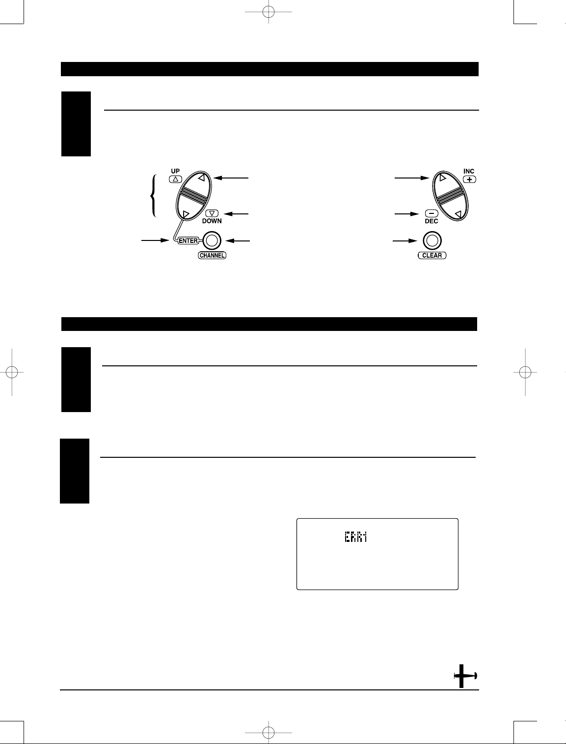
KEY INPUT AND DISPLA Y3
The Function Selection keys are used to move up and
down through the functions.The Channel key is used
to advance the channel or function selected. The
Increase and Decrease keys are used to make changes in
the selected functions.
Function Selection Keys
Up
Down
Channel
Increase
Decrease
Clear/Store
BACKUP ERROR DISPLAY4.2
All preprogrammed data is protected by a five-year
lithium battery that guards against main transmitter
battery failure. Should the lithium battery fail, the
display will indicate ERR1 regardless of the position
of the On/Off switch. If this occurs, it will be
necessary to replace the battery and reprogram all
data. All transmitter programs will return to the
factory default settings, and the data you have input
will be lost. When it becomes necessary to replace
the lithium back-up battery, contact JR Horizon
Service Center. Due to the possibility of extensive
damage caused by improper removal or replacement,
only JR Horizon Service Center is authorized to make
this change.
Press both keys at the
same time to enter or
exit the function mode.
4682 JR X-378 • ALL 7/23/02 10:07 PM Page 15
Page 16
16
X-378 MANUAL Airplane
CHAPTER 5:SYSTEM MODE • Airplane
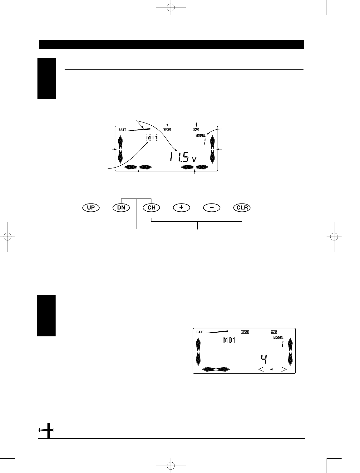
NORMAL DISPLA Y5.1
When the power switch is in the On position, the
display will read as follows:
DIRECT ACCESS DIGIT AL TRIMS5.2
The X-378 is equipped with a Direct Access Digital
Trim Value function. When at the normal display,
if a digital trim lever is moved, the screen will
automatically change to show the current trim value
for the channel being adjusted. When the trim is
returned to center, the screen will change back to the
normal display screen after a few seconds.
Current trim value for the channel being adjusted
Modulation
Type
Model Type
Model Number
Elevator Trim
Aileron Trim
Rudder Trim
To enter the System mode, press
simultaneously then turn on the
power switch. To enter the Function
model, turn on the power switch,
then press simultaneously.
In the Timer mode, press the
Channel key to start/stop the timer,
and press the Clear key to reset the
timer.
Throttle Trim
Model Name
4682 JR X-378 • ALL 7/23/02 10:07 PM Page 16
Page 17
17
X-378 MANUAL Airplane
CHAPTER 5: SYSTEM MODE• Airplane
1. Press the Down and Channel keys simultaneously.
2. Move the power switch to the On (upper)
position.
3. Use either the Up or Down key to scroll through the
menu and access the applicable function.
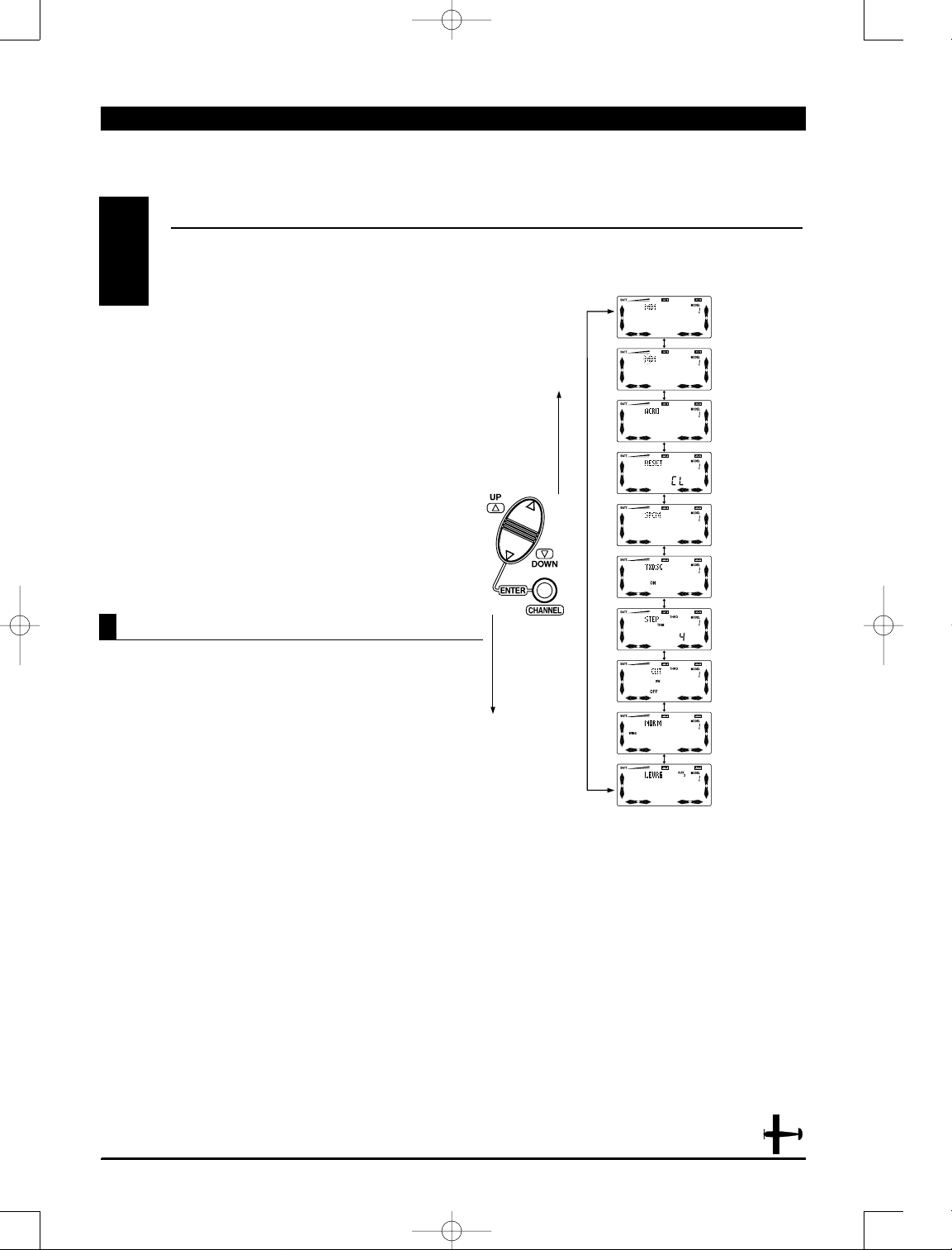
SYSTEM MODE5.3
To enter the System mode, press the Downand
Channel keys simultaneously, then turn the power
switch to the on position. The display will show the
last active program. Pressing either the Up or Down
key then scrolls through the functions one by one,
according to the system mode flowchart shown to
the right. Once the appropriate function is displayed,
changes can be made by pressing the (+) or (-) keys.
System Mode Flowchart
Information pertaining to each function is explained
on the page listed next to the function name.
Functions will appear in the same order they are
shown on this chart.
Accessing the System Mode
Model
Selection pg. 18
Model Name
Entry pg. 20
Model
Type pg. 21
Data
Reset pg. 22
Modulation
Selection pg. 23
Data
Transfer pg. 24
Trim
Step pg. 25
Throttle Cut
Switch Activation
pg. 26
Wing
Type pg. 27
Spoiler Channel
Input Selection
pg. 30
4682 JR X-378 • ALL 7/23/02 10:07 PM Page 17
Page 18
18
X-378 MANUAL Airplane
DN
UP
CH
CLR
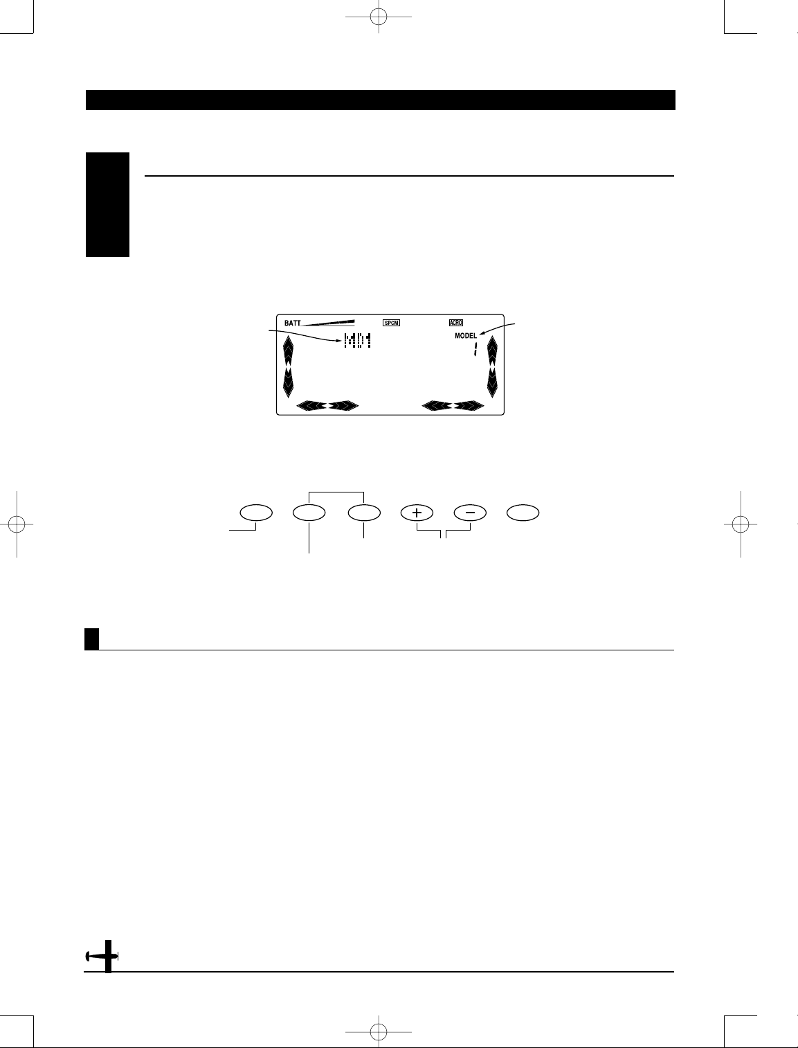
Accessing the Model Selection Function
CHAPTER 5: SYSTEM MODE• Airplane
The X-378 system offers memory for eight completely
separate models. Therefore, it is possible to have a
mixture of helicopter, airplane and glider setups
retained in memory. It is also recommended that the
Model Name Entry function be used in conjunction
with each model setup. Another very useful function
of the Model Selection function is the ability to set
one aircraft up several different ways. This is helpful
when multi-task performance is desired.
1. While pressing the Down and Channel keys, switch
the transmitter to the On position to enter the Model
Setup mode.
2. Model should be flashing on the right top portion
of the LCD. If not, press the Up or Down key until
“Model” is displayed and flashing.
3. Pressing the (+) or (-) key will select among each
of the eight models available. Notice that as each
model is selected, its name appears in the left
portion of the LCD.
4. To access the Copy Selection function, press the
Channel key.
5. To access the Model Name Entry function, press
the Up key.
6. Once the desired model is displayed on the left,
pressing the Down and Channel keys simultaneously will
exit the Model Selection function and establish the
model displayed as the new current model.
Note: When changing from one model type
to another, it is not necessary to use the Type
Selection function. This is done automatically
by the computer.
MODEL SELECTION/COPY SELECT
5.4
“Model” flashing indicates
Model Select function
Model Selection
Model Name
Spoiler Channel
Input Select
Copy
Selection
Model Name Entry
4682 JR X-378 • ALL 7/23/02 10:07 PM Page 18
Page 19
19
X-378 MANUAL Airplane
Accessing the Copy Selection Function
CHAPTER 5: SYSTEM MODE• Airplane
1. While pressing the Down and Channel keys,
move the transmitter’s power switch to the
On position.
2. Press either the Up or Down key until "Model"
appears flashing on the top right side of the LCD.
3. The number that appears below the flashing
Model is the current model. This is important to note
as only the current model will be the copied or
"from" model. It is imperative to retrieve the proper
current model prior to initiating the copy sequence.
Press the Increase or Decrease keys to select the desired
model to be copied.
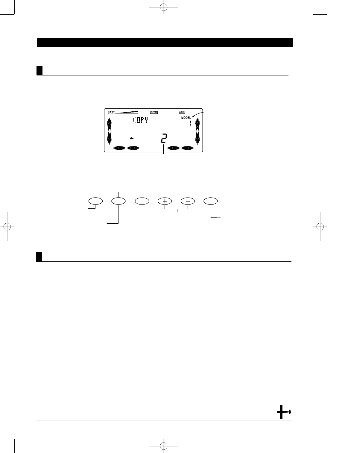
4. Next, press the Channel key once. The word "Copy"
will appear at the top left of the screen indicating
that the Copy function has been selected.
5. The large number (1-8) at the bottom center of the
LCD indicate the accepting model.
6. Now press the Increase or Decrease keys to select the
accepting model number.
Note: Always make sure that the accepting
model is either free of input or one which
you no longer want to retain in your
transmitter’s memory. Once the copying
process has been completed, the information
of the accepting model is lost and the
current model is input as the new data.
7. Once the desired accepting model is selected,
press the Clear key to complete the Copy Selection
function. The model number at the bottom of the
screen will flash several times, indicating that the
model copy function was successful. The “from”
(template) model’s name and data will now replace
that of the accepting model.
8. To access the Spoiler Channel Input Select
function, press the Down key.
9. To access the Model Naming function, press the
Up key.
10. To exit the Copy Selection function, press
the Down and Channel keys simultaneously.
The Copy Selection function enables you to copy all
of the settings of the current model to another
model within the same transmitter. This is very
useful when setting up one aircraft several different
ways or when trying an alternative setup of your
current model.
Model number to be copied
Press Clear to copy current model to
model number shown at the bottom of
the LCD screen.
Copy Selection
Model number to be copied to
Model Naming
Press at Model
Select function
to access Copy
function.
Press Increase or
Decrease to
select model
number to be
copied to.
Spoiler Channel Input Select
4682 JR X-378 • ALL 7/23/02 10:07 PM Page 19
UP
DN
CH
CLR
Page 20
20
X-378 MANUAL Airplane
Accessing the Model Name Entry Function
CHAPTER 5: SYSTEM MODE• Airplane
The X-378 allows a 3-digit name to be input for each
of the eight models available. The current model will
be displayed in the Normal display when the timer is
not active. You may also find this useful to identify
different aircraft setups.
1. While pressing the Down and Channel keys, switch
the transmitter to the On (upper) position to enter
the Model Setup mode.
2. Use the Model Selection function to select the
model you want to name. (Please refer to the Model
Selection section at this time.)
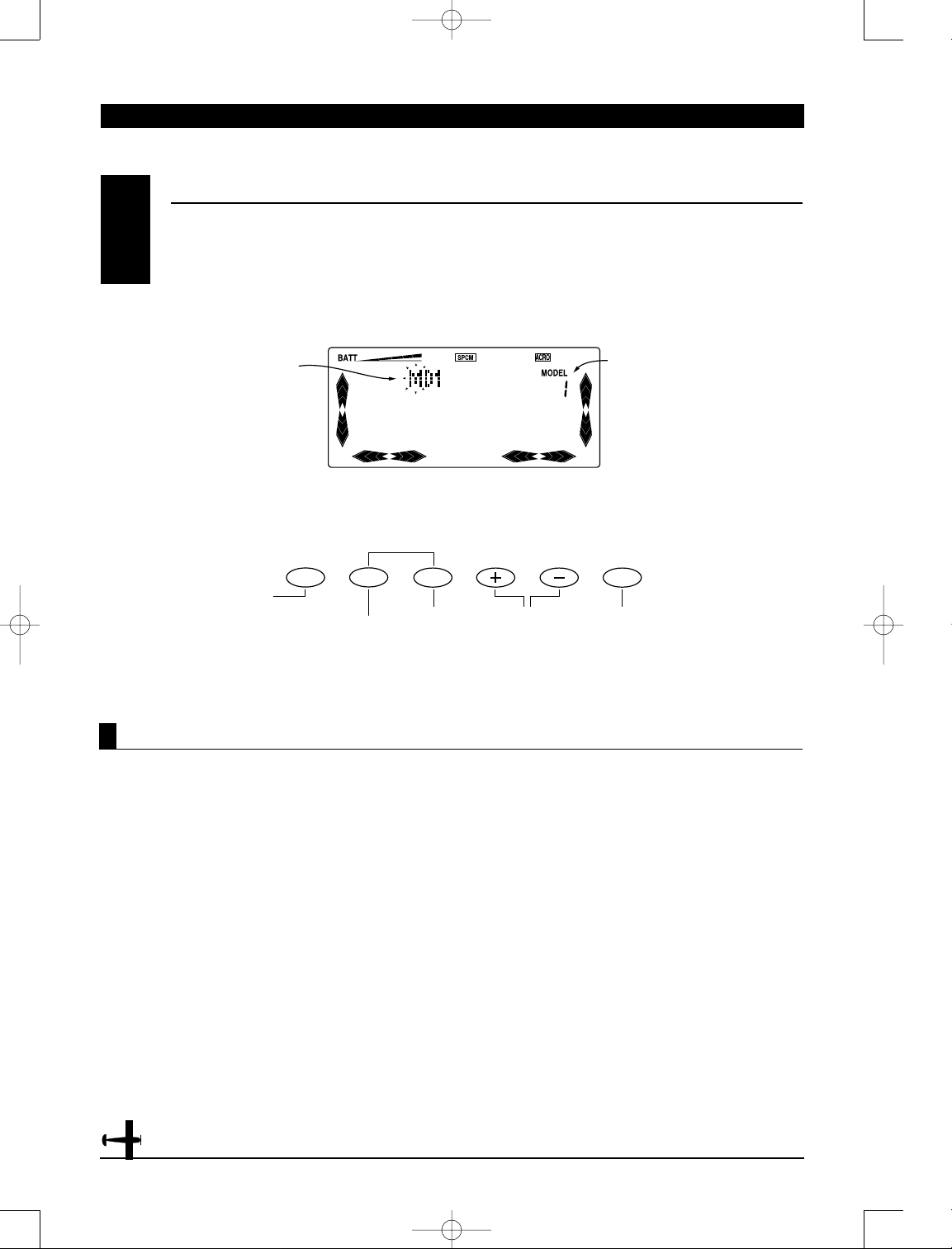
3. Press either the Up or Down key until the first digit
of the model to be named is flashing on the left
portion of the LCD.
4. The current name will be displayed in the left
portion of the LCD. Pressing the (+) or (-) key will
select the first alphanumeric character.
Note: The character being selected will flash.
5. Press the Channel key to advance the character
selection to the next character.
6. Repeat this procedure until all three characters are
selected.
7. To access the Model Selection function, press the
Down key.
8. To access the T ype Selection function, press the Upkey.
9. To exit the Model Name Entry function, press the
Down and Channel keys simultaneously.
MODEL NAME ENTRY
5.5
Model Number
Next
character
Select
characters
Clear current
character
Flashing first digit indicates
Model Naming function and
current character to be
changed
Model Type
Model Select
4682 JR X-378 • ALL 7/23/02 10:07 PM Page 20
UP
DN
CH
CLR
Page 21
21
X-378 MANUAL Airplane
CHAPTER 5: SYSTEM MODE• Airplane
Accessing the T ype Selection Function
The X-378 is capable of performing as a helicopter,
airplane or sailplane radio with full functions for each.
1. While pressing the Down and Channel keys, switch
the transmitter to the On position to enter the Model
Setup mode.
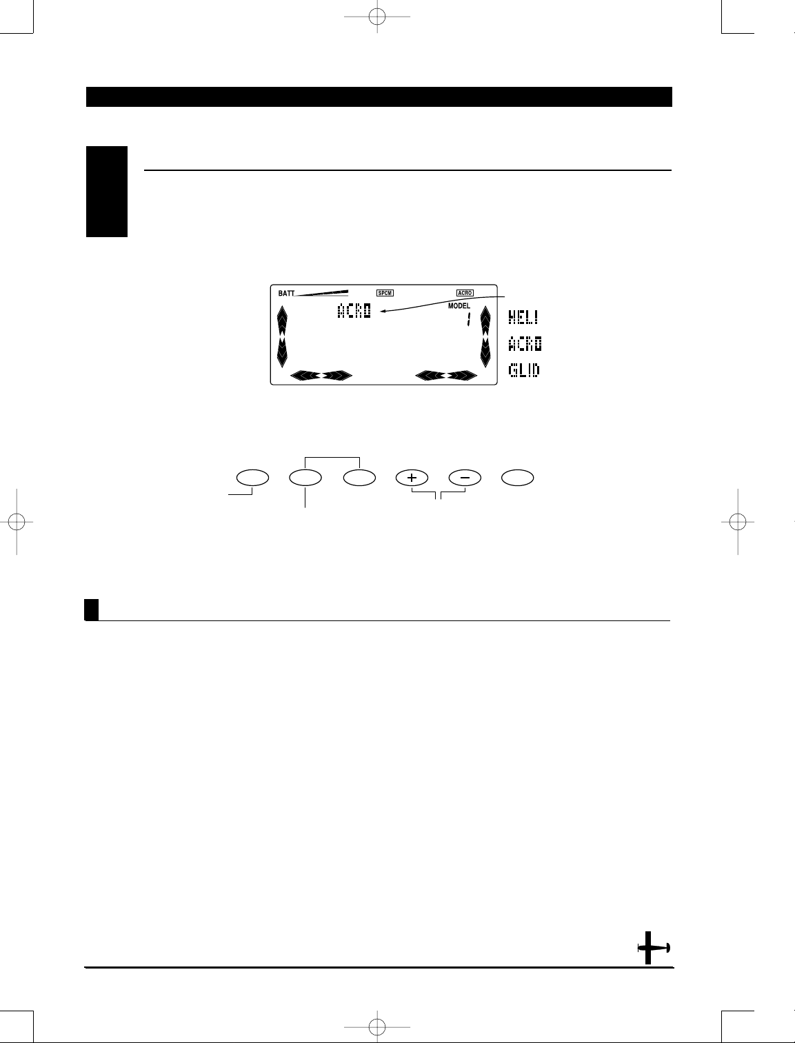
2. Press either the Up or Down keys until “Acro,” “Heli,”
or “Glid” is displayed in the left portion of the LCD.
3. Pressing either the (+) or (-) key will change the
type of model.
4. To access the Model Name Entry function, press
the Down key.
5. To access the Data Reset function, press the Up key.
6. To exit the Type Selection function, press the Down
and Channel keys simultaneously.
MODEL TYPE SELECTION
5.6
DN
UP
CH
CLR
Model Type
Data Reset
Model Naming
Press to change
model type.
4682 JR X-378 • ALL 7/23/02 10:07 PM Page 21
Page 22
22
X-378 MANUAL Airplane
CHAPTER 5: SYSTEM MODE• Airplane
1. While pressing the Down and Channel keys, switch
the transmitter to the On position to enter the Model
Setup mode.
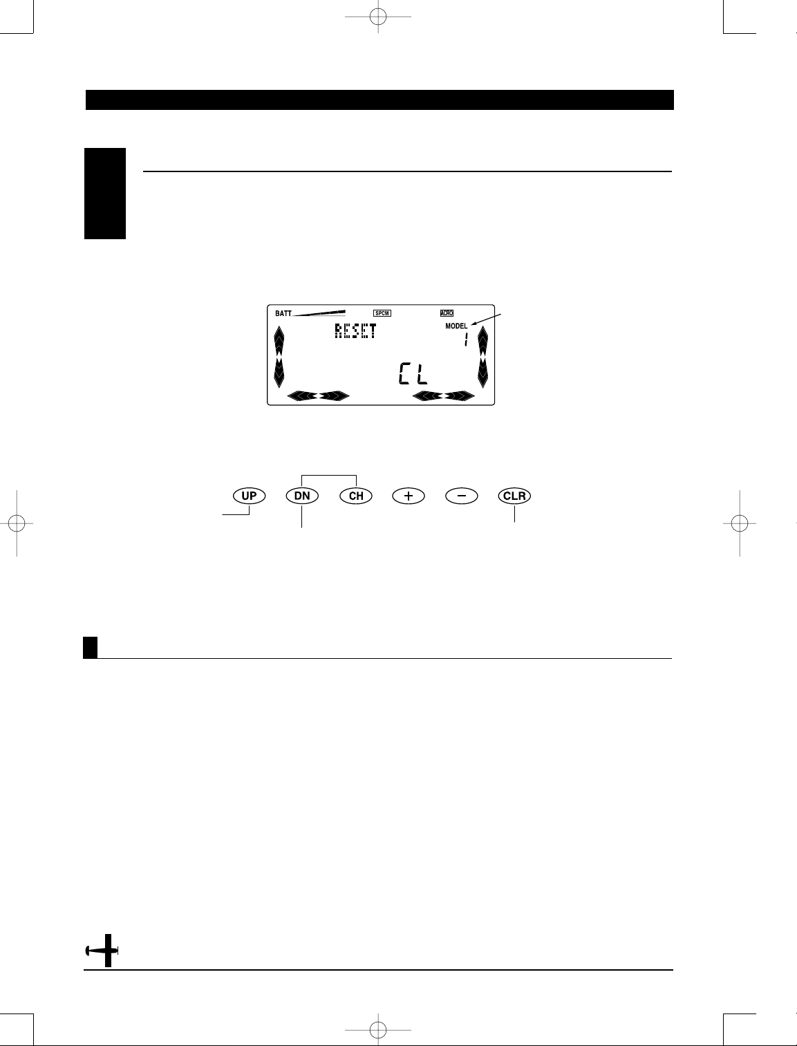
2. Press the Up or Down key until “RESET” appears in
the center of the LCD display. Be sure that the model
selected is the model you want to reset by checking
the number at the right side of the display.
3. To reset data, press the Clearkey.
4. To access the Type Selection function, press the
Down key.
5. To access the Modulation Selection function, press
the Up key.
6. To exit the Data Reset function, press both the
Down and Channel keys simultaneously.
Accessing the Data Reset Function
The Data Reset function permits you to reset all the
functions and settings for the current model to
factory conditions. Resetting does not affect the data
already programmed for other models. Be sure to
confirm that you need to reset the data of the
currently indicated model in order to prevent
accidental loss of your valuable data.
DA T A RESET
5.7
Model number to be reset
Modulation Select
Model Type
Press to Data Reset
current model.
4682 JR X-378 • ALL 7/23/02 10:07 PM Page 22
Page 23
23
X-378 MANUAL Airplane
1. While pressing the Down and Channel keys, move
the power switch to the On position to access the
System mode.
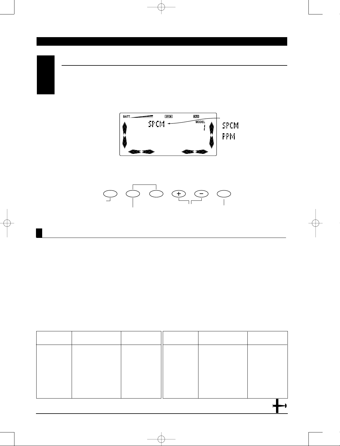
2. Press either the Up or Down key until “SPCM,”
“ZPCM,” or “PPM” appears at the top of the LCD.
3. To change among the modulation types, press
either the (+) or (-) keys.
Note: When the Data Reset function is used,
the X-378 retains the current modulation
selected for each model. This means that the
modulation type does not change.
4. Pressing the Clear key will also reset the modulation
selection to the factory preset S-PCM.
5. To access the Data Reset function, press the
Down key.
6. To access the Data T ransfer function, press the Upkey.
7. To exit the Modulation Selection function, press
the Down and Channel keys simultaneously.
Note: In the normal display, the selected
modulation type will appear in the middle of
the LCD.
Accessing the Modulation Select Function
The Modulation Selection function enables your
X-378 to transmit to a variety of JR receivers that are
already, or may soon be, in existence. You can select
from either of two types of PCM, Z-PCM or S-PCM,
depending on the Central Processing Unit (CPU)
within your receiver or from linear PPM (Pulse
Position Modulation [FM]).
Refer to the receiver compatibility chart below for
the correct modulation.
MODULA TION SELECT
5.8
TX Modulation Compatible Receivers # of Channels &
Brief Description
PPM NER-226 6 (micro)
PPM NER-228 8
PPM (FM) NER-327x 7
PPM (FM) NER-527x 7 (micro)
PPM (FM) NER-529x 9 (micro)
PPM (FM) NER-549 9
PPM NER-600 6
PPM NER-610M 6
PPM NER-700M 7
TX Modulation Compatible Receivers # of Channels &
Brief Description
Z-PCM NER-236 6 (micro)
Z-PCM NER-627XZ or
627
“G” series
7
Z-PCM NER-J329P 9
Z-PCM NER-910XZ 10
S-PCM NER-955 10
S-PCM NER-D945 10
S-PCM NER-649S 9
CHAPTER 5: SYSTEM MODE• Airplane
DN
UP
CH
CLR
Modulation
Data Transfer
Data Reset
Press to change
modulation.
Press to reset to
SPCM modulation.
4682 JR X-378 • ALL 7/23/02 10:07 PM Page 23
Page 24
24
X-378 MANUAL Airplane
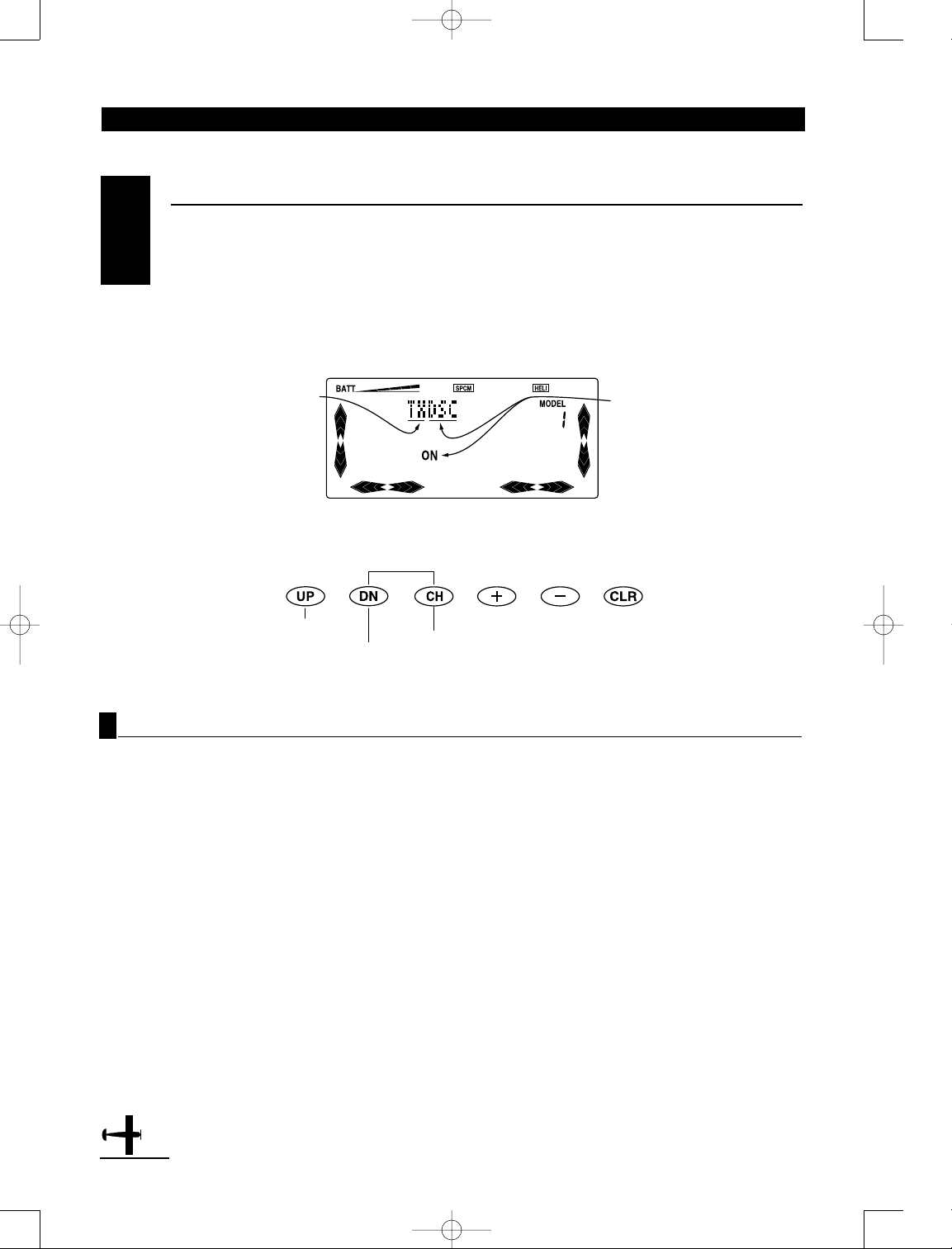
1. Both transmitters: With the main power switch off,
press the Down and Channel keys simultaneously
while turning the power switch on to enter the
System mode. The word “TXDSC” will be displayed
and flashing.
2. Press the Channel key to select Transmit (TXDSC) or
Receive (RXDSC) modes.
3. Insert the Trainer cord into each transmitter, the
letters DSC will be removed from the screen.
4. Turn off the power switch on each transmitter. The
screen will then change to read either “TXOUT” or
“RXSEL”, depending if transmit or receive modes
were selected.
Note: It is also possible to access the Data
Transfer function as follows:
5. With the main TX power switch off, press the Down
and Channel keys simultaneously while inserting the
trainer cord into the DSC jack of both transmitters.
(The transmitters will now be in System mode
automatically)
6. Press the Channel key to select transmit (TX) or
receive (RX) modes.
7. Both transmitters: In the System mode, press the
Up or Down keys until the words “TXOUT” appears on
the screen. This is the Data Transfer program.
8. Receiving Mode Transmitter (TX to receive
programming): Press the Channel key until the screen
reads “RXSEL.” The word “MODEL” will begin
flashing at the top right portion of the LCD directly
over the current model number selected.
9. Select the receiving model number by pressing the
(+) and (-) keys.
Transmitting Data
10. Press the Clear key to activate the receiving standby mode. The word “RX IN” will now be indicated on
the screen.
T ransfer Procedure
The X-378’s Data Transfer function allows for a model
from one X-378 transmitter to be sent to another
X378 transmitter by using a JR Trainer Cord (JRPA130
sold separately).
Transmitting Transmitter: It will first be necessary
to select the desired model (1-8) to be transferred to
the receiving transmitter. Access the Model Select
function and select the desired model number to be
transferred (see section 6.1 for information).
DA TA TRANSFER
5.9
CHAPTER 5: SYSTEM MODE• Airplane
Indicates that the DSC cord
needs to be inserted, and the
TX power switch needs to be
turned off
Trim Step
Modulation
Select
Press to select Transmit (TX)
or Receive (RX ) modes
Transmit Mode
4682 JR X-378 • ALL 7/23/02 10:07 PM Page 24
Page 25
25
X-378 MANUAL Airplane
CHAPTER 5: SYSTEM MODE• Airplane
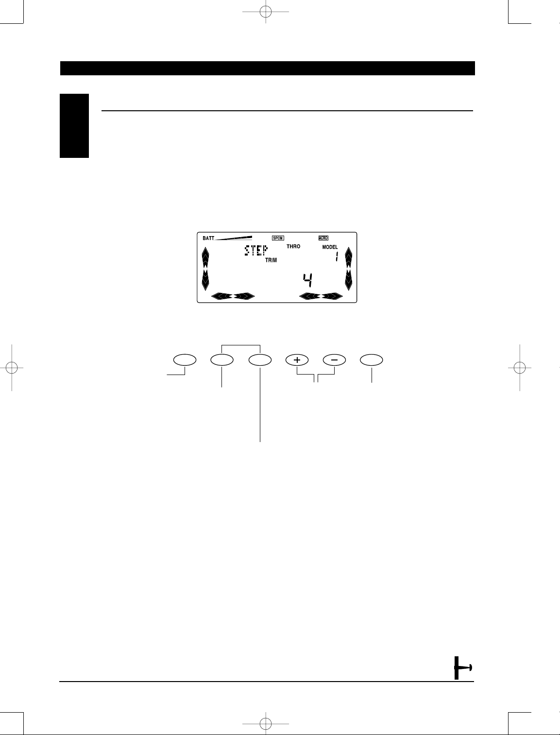
The Trim Step function allows the user to increase or
decrease the coarseness of the servo movement as
compared to the steps or beeps of the digital trim.
The total servo trim movement remains the same,
(approx. 30degree) regardless of the trim step rate
selected(1~10). The factory default setting for the
trim step function is 4, which means that for each
step (beep) of the digital trim, the servo will move in
digital increments of 4. In other words, if a finer trip
step value of 1 is selected, the servo will move in a
digital increment of 1for each step (beep) of the
digital trim. If a more coarse trim value of 10 is
selected, the servo will more in a digital increment
of 10 for each step (beep) of the digital trim lever.
TRIM STEP
5.10
Throttle Cut
Data Transfer
Press Channel to select
channel to be adjusted
(Throttle, Aileron, Elevator,
Aux 2 Lever, Flap Level).
Press Clear to reset to the
factory default (4) position.
Press the (+) or (-)
keys to increase or
decrease the trim
step rate.
4682 JR X-378 • ALL 7/23/02 10:07 PM Page 25
UP
DN
CH
CLR
Page 26
26
X-378 MANUAL Airplane
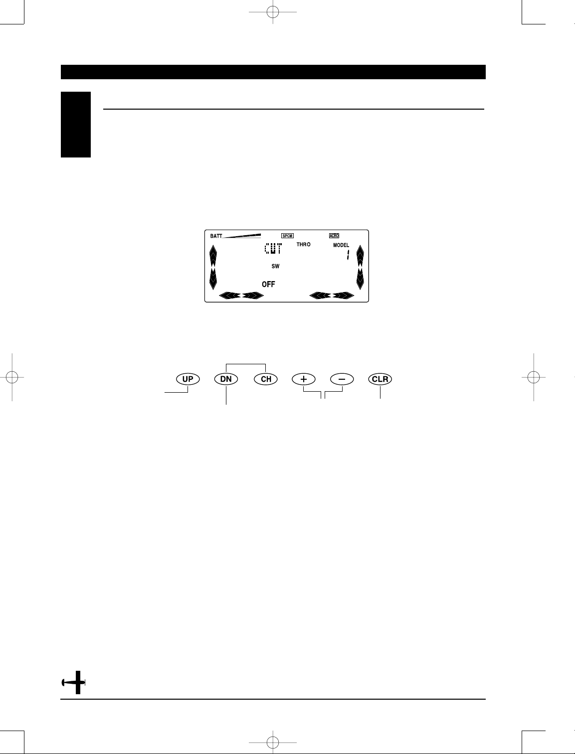
This is the function to assign Throttle Cut switch to
the push button located on upper front of the
transmitter. In the System mode, select the Throttle
Cut Switch function (CUT) by using Up or Down keys,
and press (+) or (-) keys to select the function on or
off. The Throttle Cut function is designed to return
the throttle trim to the lowest position instantly and
keep this position while the button is pressed. This
feature is used to “cut” or stop the engine without
changing the position of digital throttle trim.
THROTTLE CUT SWITCH ACTIVATION
5.11
CHAPTER 5: SYSTEM MODE• Airplane
AUX 2 Switch Selection
Trim Step
Press the (+) or (-)
keys to turn the
Throttle Cut function
on and off.
Press Clear to reset to the
factory off position.
4682 JR X-378 • ALL 7/23/02 10:07 PM Page 26
Page 27
27
X-378 MANUAL Airplane
CHAPTER 5: SYSTEM MODE• Airplane
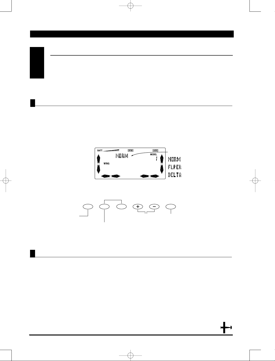
The purpose of the Wing Mixing or Wing Type
function is to eliminate mechanical or programmable mixes that would otherwise be necessary
for the proper flight of certain styles of aircraft. There
are three wing types from which to choose; select the
one that will best suit your R/C aircraft. They are as
follows: Normal, Flapperon, and Elevon (Delta). Each
of the Wing Type selections will be covered below.
This is the first wing type selection that appears on
your LCD display. Use this wing type with common
aircraft that utilize only one servo for both of the
control surfaces. Normal is the factory default setting
for the Wing Mixing function. This means that if data
reset is performed, your radio will return to this
wing type selection. Your X-378 transmitter will
also return to the normal wing mixing type if the
transmitter battery pack and the lithium battery
are both removed from the transmitter.
1. While the Down and Channel buttons are pressed,
move the power switch to the On position to access
the System mode.
2. Press either the Up or Down key until "WING"
appears at the left portion of the LCD. The current
wing type will be displayed on the upper center
portion LCD: NORM-Normal; FLPER-Flapperon;
DELT-Delta (Elevon).
3. Press either the (+) or (-) key to select the desired
wing type.
4. To access the Throttle Cut function, press the
Down key.
5. To access the Aux2/Spoiler Channel Input Select
function, press the Up key.
6. To exit the Wing Mixing function, press the Down
and Channel keys simultaneously.
Note: There are not any special receiver port
connections to be made when the Normal
Wing Type Selection is selected.
WING TYPE SELECTION
5.12
Wing type
Throttle Cut
Aux2/Spoiler Channel
Input Select
Press the (+) or (=) keys
to change the wing type.
Press the Clear key to reset to the
factory default position (NORM).
Normal Wing T ype Selection
Accessing the Normal Wing Mixing Selection
4682 JR X-378 • ALL 7/23/02 10:07 PM Page 27
UP
DN
CH
CLR
Page 28
28
X-378 MANUAL Airplane
1. While the Down and Channel buttons are pressed,
move the power switch to the On position to access
the System mode.
2. Press either the Up or Down keys until "WING"
appears in the left portion of the LCD. The current
wing type will be displayed on the Upper center
portion of the LCD: Norm-Normal; FLPER-Flapperon;
DELT-Delta (Elevon).
3. Press either the (+) or (-) key to access the
Flapperon (FLPR) Wing Type Selection.
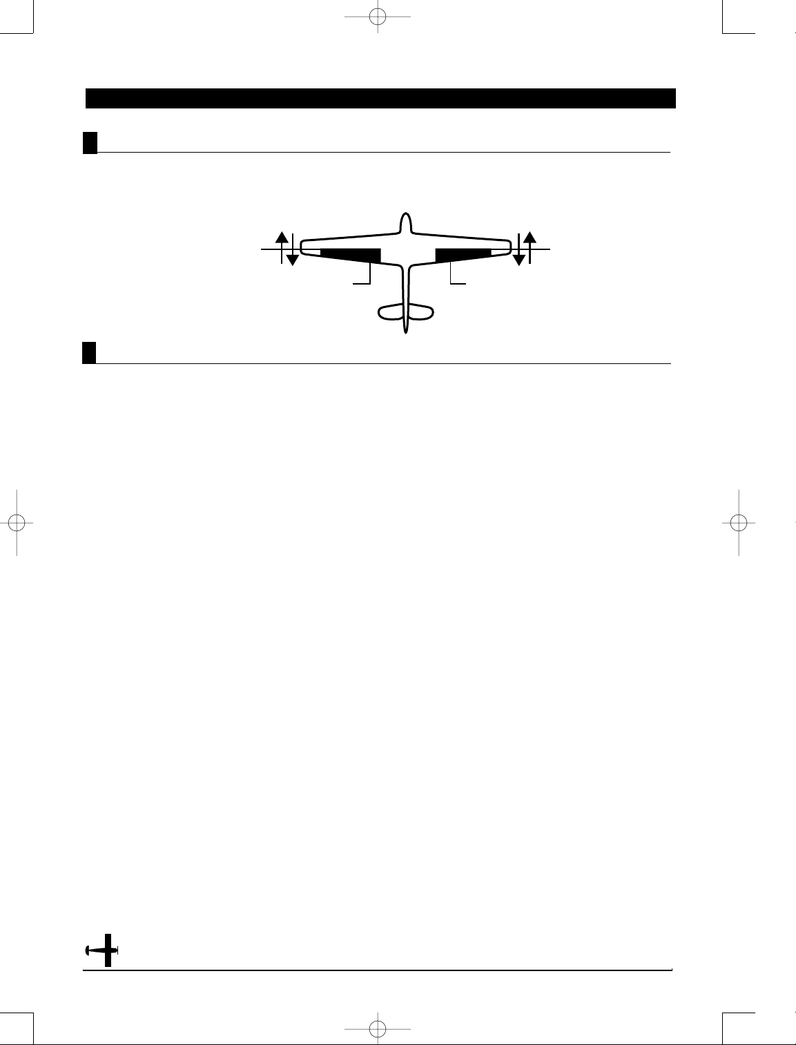
Note: For Flapperon, one servo must be used
for each aileron control surface.
4. Plug the left wing aileron servo into the Auxiliary 1
(AUX 1) port of your JR receiver. Connect the right
aileron servo into the aileron port (AILE) of your
receiver.
5. Check to make sure that the wing servos move
in the proper direction. For a right turn, the right
aileron should raise while the left aileron lowers
simultaneously. For a left turn, the opposite is true;
the left aileron should rise while the right aileron
drops. If your servos are not moving in the direction
just described, use the Servo Reversing function to
reverse the travel direction of the servo(s) that are
moving improperly. Refer to the Servo Reversing
section for information on how to reverse the travel
direction.
Note: Each servo's travel direction is
adjusted individually through the Servo
Reversing function.
Once the servos achieve their proper travel direction,
adjust their travel volume, dual rates, sub-trim and
aileron differential.
Note: The applicable channel's left or right
travel adjustment may be made individually
by accessing the Travel Adjust function. Refer
to the Travel Adjust section of this manual
for more information. The fine adjustments
of your aileron controls should be made in
the Dual-Rate function. Refer to the DualRate section for information on how to do
so. You can also adjust the neutral point of
your aileron servos individually through the
use of the Sub-Trim function. Refer to the
Sub-Trim section of this manual for more
information.
6. The flap lever located on the right face of the
transmitter controls the aileron movements as flaps.
Note: Differential is offered for the Flapperon
function of your X-378. For more information,
please refer to the Differential section of this
manual.
8. To access the Throttle Cut function, press the
Down key.
9. To access the Aux2/Spoiler Channel Input Select
function, press the Up key.
10. To exit the Wing Mixing function, press the Down
and Channel keys simultaneously.
Accessing and Utilizing the Flapperon Wing T ype Selection
Flapperon Wing T ype Selection
Connect this servo
to the aileron part of
the receiver.
Connect this servo
to the AUX 1 part
of the receiver.
CHAPTER 5: SYSTEM MODE• Airplane
Flapperons allow you to use the existing ailerons as
flaps. The ailerons can be raised or lowered in
unison as flaps, yet still remain fully operational as
the ailerons of your R/C airplane.
4682 JR X-378 • ALL 7/23/02 10:07 PM Page 28
Page 29
29
X-378 MANUAL Airplane
CHAPTER 5: SYSTEM MODE• Airplane
Delta Wing T ype Selection
Delta Wing T ype Selection
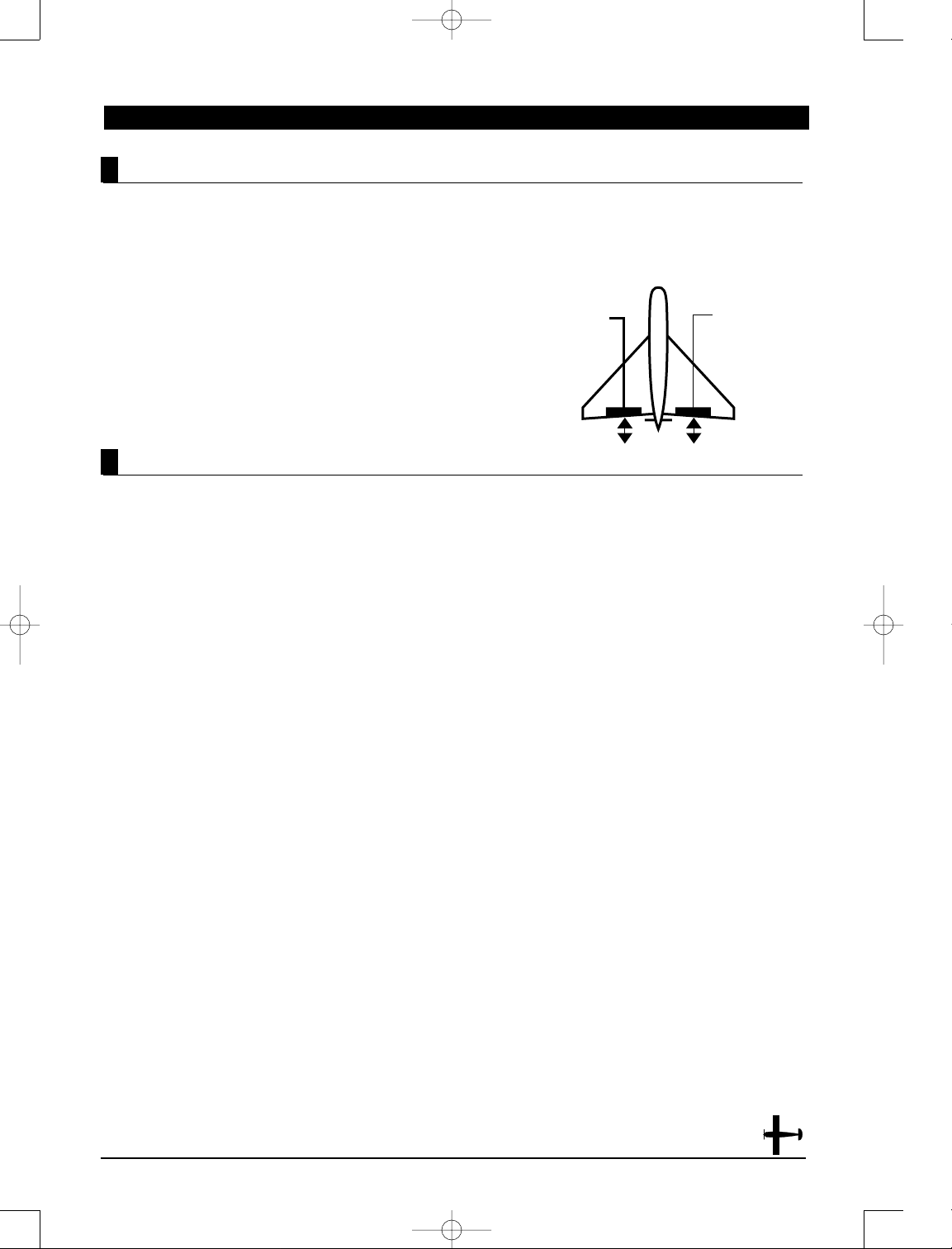
Delta or Elevon is the final Wing Mixing selection in
your X-378. This style of aircraft also employs two
wing servos. However, there is not an elevator
present. Instead, at an elevator stick input, the two
wing servos function in conjunction with one another
to create an up/down movement of the aircraft. The
wing itself functions as if it were the elevator. Also,
when an aileron control is given, the two wing servos
move in opposition to one another to function as
ailerons.
1. While the Down and Channel keys are pressed, move
the power switch to the On position to access the
System mode.
2. Press either the Up or Down key until "WING"
appears in the left portion of the LCD. The current
wing type will be displayed on the upper center
portion of the LCD: NORM-Normal; FLPERFlapperon; DELTA-Delta (Elevon).
3. Press either the (+) or (-) key to select the Delta
(Elevon) Wing Type function.
Note: With the Delta function, one servo
must be used for each elevon, i.e., a separate
servo for each wing half.
4. Plug the left elevon servo to the aileron (AILE) of
your JR receiver. Connect the right elevon servo into
the elevator (ELEV) port of your receiver.
5.Check to make sure that the servos move in the
proper direction. When an input is given from the
elevator stick, they should move in unison to achieve
the proper up/down elevator command. If your
servos do not move in the proper direction as
described above, use the Servo Reversing function
to reverse the travel direction.
Note: Each servo's direction is adjusted
individually through the Servo Reversing
function. For more information, refer to the
Servo Reversing section in this manual.
6. Once the servos have achieved their proper travel
direction, adjust their travel direction, travel volume,
dual rates, sub-trim and aileron differential.
Note: The applicable channel's left or right,
up or down travel adjustments can be made
individually. Refer to the Travel Adjust
section in this manual for more information.
7. Relative to the note above, each servo's travel
volume is automatically reduced to 75% of the
operating range. This is to ensure that the servo
does not operate beyond its capabilities. Failure to
observe extreme caution when adjusting the value
for the elevon servos may result in damage to the
servos by over traveling.
Note: Fine adjustments of the elevons
should be made in the Dual-Rate function.
For more information, refer to the Dual-Rate
section in this manual. You can also adjust
the neutral point of your elevon servos
individually. To do so, use the Sub-Trim
function as described in the Sub-Trim
section of this manual. Differential is offered
for the elevon function of your XP-783. For
more information, refer to the Differential
Aileron Mixing section of this manual.
9. To access the Throttle Cut function, press the
Down key.
10. To access the Aux2/Spoiler Channel Input Select
function, press the Up key.
11. To exit the Wing Mixing function, press the Down
and Channel keys simultaneously.
Connect this servo
to the elevator part
of the receiver.
Connect this servo
to the aileron port of
the receiver.
4682 JR X-378 • ALL 7/23/02 10:07 PM Page 29
Page 30
30
X-378 MANUAL Airplane
AUX 2/SPOILER CHANNEL INPUT SELECT
5.13
CHAPTER 5: SYSTEM MODE• Airplane
Accessing the Spoiler Channel Selection Function
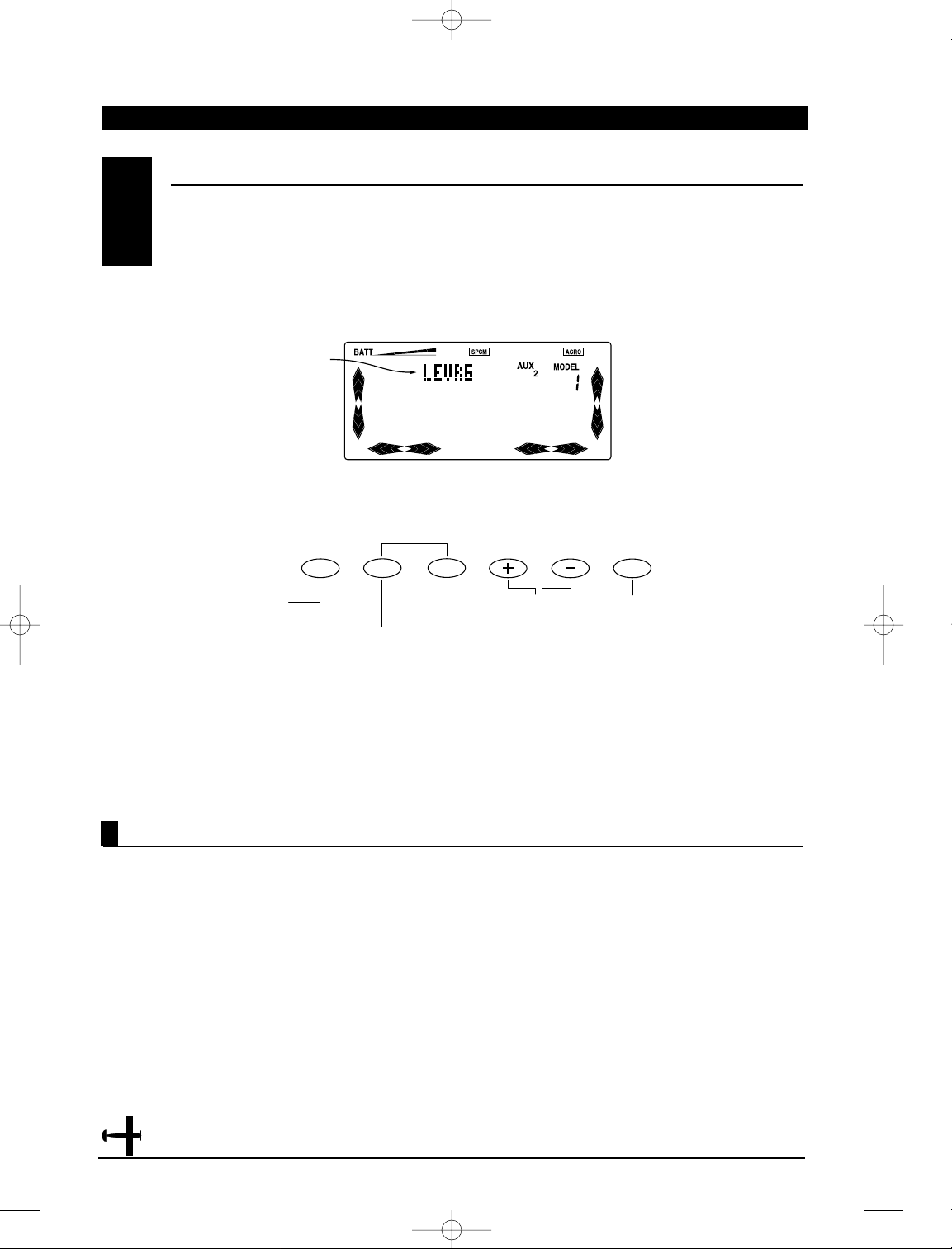
The purpose of the Aux 2/Spoiler Channel Input
Selection function is to assign the activation device
for the AUX 2 channel. The Lever provides
proportional control, while the switch allows On/Off
function of the AUX 2 channel.
Note: If the spoiler is coupled to the landing
system, the spoiler lever or switch will not
operate the spoiler's channel and "LAND" will
appear in this program.
1. While pressing the Down and Channel keys, switch
the transmitter to the On position to enter the
System Mode.
2. Press either the Up or Down key until "AUX 2"
appears at the upper right portion of the LCD.
3. Press either the (+) or (-) key to assign the
desired switch (LEVRG or MIX SW)
4. To access the Wing Type function, press the
Down key.
5. To access the Model Select function, press the
Up key.
6. To exit the Aux2/Spoiler Channel Input Selection
function, press the Down and Channel keys
simultaneously.
DN
UP
CH
CLR
Press the Clear key to
reset to the factory
default position (LEVRG)
Switch selected (LEVRG
or MIX SW)
Model Select
Wing Type
Press the (+) or (-) key to
select the desired switch
to be assigned.
4682 JR X-378 • ALL 7/23/02 10:07 PM Page 30
Page 31

31
X-378 MANUAL Airplane
Accessing the Mode Function
To enter the Function mode, switch the transmitter
power switch to the On position. Press the Down and
Channel keys simultaneously, and the display will
show the last active program. Pressing either the Up
or Down key then scrolls through the functions one by
one, according to the Function Mode Flowchart
shown on the right. Once the appropriate function is
displayed, changes can be made by pressing the (+)
or (-) keys. To select another channel of a particular
function, press the Channel key. If you transfer to a
different function that is channel selectable, the
display will show the same channel. For example, if
you are adjusting the dual rate of the elevator and
you change to the Exponential function, the channel
remains elevator. The Function mode is the most
often used system to input data.
Function Mode Flowchart
Information pertaining to each function is explained
on the page listed next to the function name.
Functions will appear in the same order they are
shown on this chart.
1. Move the power switch to the On position.
2. Press the Down and Channel keys simultaneously.
3. Use either the Up or Down to scroll through the
menu and access the applicable function.
FUNCTION MODE
6.1
CHAPTER 6: FUNCTIONS (FUNCTION MODE) • Airplane
Servo Reversing
pg.32
Dual Rate pg.33
Exponential pg.35
Sub-Trim pg.38
Travel Adjust
pg.39
Elevator-toFlap Mixing pg. 40
Aileron-toRudder Mixing
pg. 42
Landing Mode
pg. 44
Snap Roll
Function pg.46
Differential
Aileron Mixing
pg. 48
Flap Lever
Adjustment
pg.
Programmable
Mixing pg. 50
Fail-Safe (only
visible when PCM
Modulation is
selected) pg. 52
Trainer Function
pg. 59
Timer Function
pg. 62
4682 JR X-378 • ALL 7/23/02 10:07 PM Page 31
Page 32

32
X-378 MANUAL Airplane
CHAPTER 6: FUNCTIONS (FUNCTION MODE) • Airplane
Accessing the Reverse Switch Function
The Reverse Switch function is an electronic means
of reversing the throw of a given channel (servo). All
seven channels of the X-378 offer reversible servo
direction. This will ease setup during the servo
installation into your aircraft.
1. Place the transmitter switch in the on position.
2. Access the Function mode by pressing the Down
and Channel keys simultaneously.
3. Press either the Up or Down key until the “REV.”
appears in the upper left corner of the LCD.
4. Using your transmitter’s control sticks, switches
and potentiometers, move the control surfaces of
your aircraft. Note the travel direction of each of the
corresponding control surfaces.
5. After you have determined which channel(s) need
to have the throw directions reversed, use the
Channel key to call up the appropriate channel.
6. Press either the (+) or (-) keys to change the travel
direction of the servo. Pressing the Clear key returns
the travel direction to Normal.
7. You can observe the change in the travel direction
by moving the appropriate control at this time.
8. To access the Timer function, press the Down key.
9. To access the Dual Rate function, press the Upkey.
10. To exit the Reverse Switch function, press the
Down and Channel keys simultaneously.
SERVO REVERSING
6.2
Channel to be
adjusted
Press the (+) or (-)
keys to change the
servo direction.
Press Channel to change
to the desired channel to
be adjusted.
Press Clear to reset
to the factory normal
direction.
THRO: Throttle
AILE: Aileron
ELEV: Elevator
RUDD: Rudder
GEAR: Retract
Landing Gear
FLAP: Flap (AUX 1)
SPOI: Spoiler
Dual-Rate Function
Timer Function
4682 JR X-378 • ALL 7/23/02 10:07 PM Page 32
Page 33

33
X-378 MANUAL Airplane
Accessing the Dual-Rate Function
Dual rates are available for the aileron, elevator and
rudder channels of your R/C aircraft. There is also an
automatic dual rate setting to link your aileron,
elevator, and rudder dual rates to the flight model
switch. This automatic Dual-Rate function is
discussed in a separate section that follows. Dual
rates may be defined as the ability to vary the travel
or throw rate of a servo from a switch. Due to the
differing travel rates, you will find that the sensitivity
of the control either increases or decreases
accordingly. A higher rate, or travel, yields a higher
overall sensitivity. You may find it easier to think
of the Dual-Rate function as double-rates or halfrates.The Dual-Rate function works in conjunction
with the Exponential function to allow you to
precisely tailor your control throws. You may want to
consult the section defining exponential for further
information.
1. Place the transmitter power switch in the
on position.
2. Access the Function mode by pressing the Down
and Channel keys simultaneously.
3. Press either the Up or Down key until “D/R” appears
in the upper left corner of the LCD.
4. Press the Channel key until the desired channel
(aileron, elevator, rudder or automatic dual rates)
appears.
5. Select the switch position for which you want
to adjust the rate. The number to the upper right of
the current rate value on the display indicates the
current position of the Dual-Rate switch for the
channel that you have selected. Either a 0 or a 1 will
be shown, corresponding to the position of the
switch. To select the opposite switch position, move
the appropriate Dual-Rate switch to the opposite
position. The number that appears above the current
rate value reflects the change.
6. Adjust the rate for the channel and the switch
position that you have just selected. To decrease the
throw rate, press the (-) key. To increase the throw
rate, press the (+) key. As stated previously, the
adjustable rate is from 0-125% for each switch
position and channel.
DUAL RA TES
6.3
CHAPTER 6: FUNCTIONS (FUNCTION MODE) • Airplane
Channel to
be adjusted
Exponential
Servo Reversing
Press Channel to select
Aileron, Elevator, Rudder,
or Auto D/R to be adjusted.
Press (+) or (-)
to increase or
decrease D/R
values.
Channel to be
adjusted D/R
switch position.
(0 or 1)
Press Clear to reset
to factory default
settings.(100%)
The amount of travel is adjustable from 0-125% in 1%
increments. The factory setting, or default value, for
both the 0 and 1 switch positions is 100%. Either
switch position may be selected as the low or high
rate by placing the switch in the desired position and
adjusting the value accordingly.
4682 JR X-378 • ALL 7/23/02 10:07 PM Page 33
Page 34

34
X-378 MANUAL Airplane
CHAPTER 6: FUNCTIONS (FUNCTION MODE)
•
Accessing the Dual-Rate Function (continued)
Note: You can observe the servo changes by
moving the respective stick while increasing
or decreasing the values. The control changes
accordingly. T o clear the dual rate for the respective
channel and switch position, press the Clear
key. After the dual rates have been dialed in
to your satisfaction, we suggest that you begin
to adjust the exponential values. Refer to the
Exponential section for more information.
7. To access the Servo Reversing function, press
the Down key.
8. To access the Exponential function, press the
Up key.
9. To exit the Dual-Rate function, press the Downand
Channel keys simultaneously.
Automatic Dual-Rate
If the Automatic Dual-Rate function AUTO is active
(on), when switching the flight mode switch, aileron,
elevator and rudder channel Dual-Rate values are
switched to preset values settled by position 1.
Press Clear to return to the
factory default setting (off).
Press the (+) or (-)
keys to turn the
Auto D/R function
on or off.
To access this function, move to the D/R (Dual-Rate)
screen, and press the Channel button until the word
“AUTO” appears at the top center of the screen, with a
small box with the number 1 to the far left. This would
indicate the Auto D/R function for Flight mode 1.
Press the (+) or (-) keys to turn the function on or off.
Repeat this procedure for flight modes 2 and
Hold (HO).To confirm that the Auto D/R is
functioning, simply move the flight mode switch
while at any of the normal D/R channel screens. If
the Auto D/R is functioning, the screen will indicate
D/RAT, and the D/R switch position at the far right
of the screen will change from 0 to 1 as the switch
is moved.
Flight mode position to be adjusted
Condition (off or on)
Flight mode position to
be adjusted
Exponential
Servo Reversing
Press Channel to
select the desired
flight mode to adjust
(1,2 or HO).
4682 JR X-378 • ALL 7/23/02 10:07 PM Page 34
Page 35

35
X-378 MANUAL Airplane
Accessing the Exponential Function
Programmable exponential adjustments are offered
on the aileron, elevator, and rudder channels of your
R/C aircraft. Exponential is a function that allows you
to tailor the response rate of the stick controls. The
purpose of exponential is to reduce the sensitivity in
the middle portion of stick movement, while still
allowing full travel at the end of the stick movement.
In other words, the end result (travel) remains the
same, although exponential changes the rate at
which it achieves this travel.
The adjustable range of the Exponential Function is
from 0-100%. Zero percent (0%) is linear stick control
which means that the response rate is equal
throughout the stick control. 100% is full
exponential. The larger the exponential value, the
less servo action or sensitivity you will notice around
the neutral setting.
Note: The Exponential function operates in
conjunction with the Dual-Rate function. It is
imperative to understand the Dual-Rate
function prior to adjusting the exponential
values. Exponential may be selected for
either the high or low rate or both.
1. Place the transmitter power switch in the On position.
2. Press the Down and Channel keys simultaneously to
access the Function mode.
3. Press either the Upor Down key until “EXP” (Exponential)
appears in the upper left corner of the LCD.
4. Press the Channel key until the desired channel
(aileron, elevator, rudder or AUTO) appears.
5. Select the switch position for which you want to
adjust the exponential rate. The number directly
above the exponential value on the display indicates
the current position of the Dual-Rate switch for the
channel that you have selected. Either a 0 or 1 will be
shown, corresponding to the position of the switch. To
select the opposite switch position, move the
appropriate Dual-Rate or Flight mode switch to the
opposite position. The number that appears directly
above the Exponential value will reflect the change.
6. Adjust the rate for the channel and the switch
position that you have just selected. To increase the
exponential rate, press the (+) key. The adjustable
rate is from linear (0%) to100% for each switch
position and channel.
Note: Exponential is an acquired feel. It may
take several test flights to achieve the proper
amount of exponential that fits your flying style.
8. To access the Dual-Rate function, press the Downkey.
9. To access the Sub-Trim function, press the Up key.
10. To exit the Exponential Function, press the Down
and Channel keys simultaneously.
EXPONENTIAL6.4
CHAPTER 6: FUNCTIONS (FUNCTION MODE) • Airplane
Press Clear to reset
values to the factory
default position.
Channel to
be adjusted
Sub-Trim function
Dual-Rate
function
Press to select Aileron, Elevator, Rudder,
or AUTO position to be adjusted.
Press the (+) or (-) keys to
Increase or decrease the
Exponential values, or to
activate or inhibit the
Exponential function in the
Auto Dual-Rate modes.
Dual-Rate switch
position to be
adjusted
4682 JR X-378 • ALL 7/23/02 10:07 PM Page 35
Page 36

36
X-378 MANUAL Airplane
Automatic Rudder Exponential Rate
When the Automatic Rudder Exponential Rate
function is active, the throttle stick position will
automatically switches among the rudder
exponential rates that you have selected in the
exponential section listed above. This means that, as
you advance or pull back the throttle stick, the
rudder exponential rates automatically change.
When the throttle stick is moved anywhere from low
to approximately 70% of full travel, the low (position
0) rudder exponential rates are active; once the
throttle is fully advanced, high (position 1) rudder
exponential will automatically return.
You will find that the automatic rudder exponential
rate is very useful in overcoming special flying
problems. The idea is to have less rudder sensitivity
at high throttle positions because the rudder is more
effective at higher speeds. Conversely, it is more
efficient to have more rudder sensitivity at lower
speeds because the rudder is not as effective. The
Automatic Rudder Exponential Rate function can
also be used in the opposite manner to reduce the
sensitivity of the rudder for takeoffs with models that
have sensitive steering.
CHAPTER 6: FUNCTIONS (FUNCTION MODE) • Airplane
On/Off
Sub Trim
Dual-Rate
Press the (+) or (-)
keys to turn the AUTO
function on and off.
Press the Clear key to
reset to the factory
default position (Off).
Press Channel to access
AUTO rate function from
exponential screen.
4682 JR X-378 • ALL 7/23/02 10:07 PM Page 36
Page 37

37
X-378 MANUAL Airplane
CHAPTER 6: FUNCTIONS (FUNCTION MODE) • Airplane
1. Place the transmitter switch in the On
(upper) position.
2. Access the Function mode by pressing the Down
and Channel keys simultaneously.
3. Press either the Up or Down key until "D/R" appears
in the upper center portion of the LCD.
4. Press the Channel key until "AUTO" is displayed.
5. Pressing either the (+) or (-) keys changes the
automatic rudder Exponential rate from off to on. To
return the auto rudder exponential rate to the "Off"
position, press the (+) or (-) keys one more time or
press the Clear key.
6. When the Automatic Rudder Exponential Rate
function is active, "EXPAT" will be displayed on the
rudder exponential rate display.
7. The exponential rate value selected for switch
position 0 will be the value used for low throttle stick
operation (Up to approximately 70%); the
exponential rate value selected for switch position 1
will be the exponential value used when the throttle
stick is in the high (full) position.
8. To access the Dual-Rate function, press the
Down key.
9. To access the Sub Trim function, press the Up key.
10. To exit the Automatic Rudder Exponential Rate
function, press the Down and Channel keys
simultaneously.
Note: In order for the Automatic Rudder
Exponential Rate function to operate, the
rudder dual rate switch must be in the 0
position. Moving the dual rate switch to the
1 position negates the operation of the
automatic rudder exponential rate and
defaults the rate to the value for switch 1.
To confirm that the Auto Rudder Exponential Rate is
functioning, simply move the throttle stick while at
the EXPAT screen. If the Auto Rudder Exponential is
functioning, the exponential rate switch position at
the far right of the screen will change from 0 to 1 as
the throttle stick is moved.
Adjusting the Automatic Rudder Exponential Rates
4682 JR X-378 • ALL 7/23/02 10:07 PM Page 37
Page 38

38
X-378 MANUAL Airplane
CHAPTER 6: FUNCTIONS (FUNCTION MODE) • Airplane
The Sub-Trim Adjustment function allows you to
electronically fine-tune the centering of your servos.
Individually adjustable for all seven channels with a
range of ±125% (+/-30 degrees servo travel), the subtrims can be set for the same neutral settings for
each model stored in the transmitter’s memory.
The sub trim functions provides precise servo arm
neutral positioning if rotating the servo arm will
not allow the desired servo arm position.
1. Place the transmitter power switch in the
On position.
2. To Access the Function mode, press the Downand
Channel keys simultaneously.
3. Press either the Up or Down key until “SUBTRIM”
appears in the upper middle portion of the LCD.
4. Press the Channel key until the desired channel
appears.
5. Press the (+) or (-) key to establish the desired
amount and direction of Sub-Trim.
Note: A (+) or (-) symbol appears to the left of
the sub trim value to indicate the direction of
Sub-Trim input.
Caution: Do not use excessive sub-trim
adjustments since it is possible to overrun
your servo’s maximum travel if it is off-center.
Remember that it is a trim convenience
function. It is not intended to take the place
of the proper mechanical trim adjustments
that are necessary on any R/C model. An
offset servo will also produce a
differential effect.
6. To access the Exponential function, press the
Down key.
7. To access the T ravel Adjust function, press the Up key.
8. To exit the Sub-Trim function, press the Down and
Channel keys simultaneously.
Accessing Sub-T rim Adjustment Function
SUB-TRIM6.5
Press Clear to reset to the
factory default settings (0%).
Press the (+) or (-) keys
to increase or decrease
the Sub-Trim value.
Channel to
be adjusted
Sub-Trim Value
Travel Adjust
Exponential
Press to select desired
channel to be adjusted (1-7).
4682 JR X-378 • ALL 7/23/02 10:07 PM Page 38
Page 39

39
X-378 MANUAL Airplane
The purpose of Travel Adjust, also known as endpoint
adjustment or adjustable travel volume, is to offer
you precise servo control deflection in either
direction of servo operation. The X-378 offers travel
adjust for all seven channels. The Travel Adjust range
is from 0-150% (0 degrees to 60 degrees) from
neutral, or center, and it can be adjusted for each
direction individually. The factory default (Data
Reset) value is 100% for each direction of servo travel.
TRAVEL ADJUST
6.6
Accessing the T ravel Adjust Function
1. Place the transmitter power switch in the
On position.
2. Access the Function mode by pressing the Down
and Channel keys simultaneously.
3. Press either the Up or Down key until “TRAVL”
appears in the upper middle portion of the LCD.
4. Press the Channel key until the desired channel
appears.
5. Move the appropriate control stick (lever, switch,
etc) to the right or left of center to the direction of
travel you want to adjust. An arrow to the right of the
travel adjust value will reflect the current position to
be adjusted. Using our example above, if the aileron
stick is moved to the left, a left-facing arrow will
appear to the left of the travel adjust value on the
LCD screen.
6. After the control stick or switch is placed in the
direction of travel to be adjusted, press the (+) or (-)
key until the proper amount of servo travel is shown
on the lower right side of the LCD. Press the (+) key
to increase the amount of servo travel. Press the (-)
key to decrease the amount of servo travel.
7. Follow the same procedure for the remaining
channels.
8. To access the Sub-Trim function, press the Down key.
9. To access the Throttle Hold (or CCPM Mix if
activated) function, press the Up key.
10. To exit the Travel Adjust function, press the Down
and Channel keys simultaneously.
CHAPTER 6: FUNCTIONS (FUNCTION MODE) • Airplane
Press Clear to reset to factory
default settings (100%).
Press the (+) or (-)
keys to increase or
decrease the Sub
Trim values.
Travel direction to be
adjusted (left/right,
up/down, etc)
Channel to be adjusted
Press Channel to select
the desired channel to
be adjusted.
Elevator to
Flap Mixing
Sub-Trim
4682 JR X-378 • ALL 7/23/02 10:07 PM Page 39
UP
DN
CH
CLR
Page 40

40
X-378 MANUAL Airplane
1. Place the transmitter power switch in the
On position.
2. Access the Function mode. To do so, press the
Down and Channel keys simultaneously.
Press either the Up or Down key until "ELEV-FLAP"
appears in the center portion of your LCD.
Note: If the Flap Mixing switch is not in the
uppermost position, the position indicator
will read "OFF". The flap mixing switch must
be in the upper (elevator) mix position in order
to make adjustments to the flap mixing value.
3. Move the elevator stick in the direction you want
to mix with flaps.
Note: The position indicator will reflect this
change by replacing the up arrow with a down
arrow or vice-versa. A down arrow indicates up
elevator, and an up arrow indicates down
elevator (arrow position is indicating stick
position, not elevator direction.
5. Press the (+) or (-) key to increase or decrease the
amount of flaps to be mixed. If you want to reverse
the flap travel, press the Clear key, bringing the
mixing value to the factory default (0%), and increase
the value using the opposite key (+) or (-) from the
key originally selected.
6. Once you have adjusted the first mixing position
(up or down), place the elevator stick in the opposite
direction and follow Step 5 above to adjust the
second elevator mixing value.
7. To access the Travel Adjust function, press the
Down key.
8. To access the Aileron-to-Rudder Mixing function,
press the Up key.
9.To exit the Elevator-to-Flap Mixing function, press
the Down and Channel keys simultaneously.
Accessing the Elevator to Flap Mixing Functiion
When this system is active and a value of flaps is
input, the flaps will be deflected each time the
elevator stick is used. The actual flap movement is
adjustable for both up and down elevator. The most
frequently used application is up elevator/down flaps
and down elevator/up flaps. When used in this
manner, the aircraft pitches much more quickly than
normal. The upper-most position of the Flap Mixing
switch activates the Elevator-to-Flap Mixing circuitry.
ELEVATOR-TO-FLAP MIXING
6.7
CHAPTER 6: FUNCTIONS (FUNCTION MODE) • Airplane
Press the Clear key to
reset to the factory
default position (0%).
Up/Down arrows change when
the elevator stick is moved, and
indicate current position to be
adjusted
Current mixing
value
Current mix switch position (Up=ON, center or
low position displays OFF)
Aileron-to-Rudder
Mixing
Travel Adjust
Press the (+) or (-) keys
to increase or decrease
the mixing value for
each position.
4682 JR X-378 • ALL 7/23/02 10:07 PM Page 40
UP
DN
CH
CLR
Page 41

41
X-378 MANUAL Airplane
CHAPTER 6: FUNCTIONS (FUNCTION MODE) • Airplane
Note: Only the elevator input indicated by
the LCD will be cleared. For example, if the
up arrow were displayed and CLR were
pushed, the down arrow value would still be
retained by the transmitter. In order to
change elevator operating direction, move
the elevator control stick in the direction you
want to mix with flaps. Using our example,
we would input down elevator. The down
arrow would be displayed at the lower left
portion of the LCD. Our mixing value would
also change to reflect our input. If the Flap
Mixing switch is not in the uppermost
position, the position indicator will change
from “On’’ to “Off’’. This indicates that the
Elevator-to-Flap Mixing function is not
currently active. Although the current mixing
value will still be displayed, it will not be
possible to alter this value until the mix
switch is returned to the on position.
4682 JR X-378 • ALL 7/23/02 10:07 PM Page 41
Page 42

42
X-378 MANUAL Airplane
DN
UP
CH
CLR
This form of mixing is designed so that when input
to the aileron stick is given, the rudder servo will also
move, eliminating the need to coordinate these
controls manually.
When adjusting, if an opposite mixing direction of
the rudder servo is required, simply press the (+) or
(-) keys to change the mixing value from a (+) to (-)
or a (-) to a (+). This will reverse the mixing direction
of the rudder from its original direction. The switch
used to activate this mix can also be selected as
explained below. The factory default mix switch for
the Aileron-to-Rudder mix function is Rudder
D/R/Mix switch located at the upper right side of the
transmitter.
1. Place the transmitter power switch in the
On position.
2. Access the Function mode. To do so, press the
Down and Channel keys simultaneously.
Press either the Up or Down key until "AILE-RUDD"
appears in the center portion of your LCD.
Note: If the current mixing switch is not in the
on position, the position indicator will read
"OFF." The current mixing switch must be in
the On position in order to make adjustments
to the Aileron- to-Rudder mixing value.
4. With the current mix switch on, press the (+) or (-)
key to increase or decrease the amount of rudder to
be mixed with aileron. If you want to reverse the
Rudder Mix direction, press the Clear key, bringing
the mixing value to the factory default (0%), and
increase the value using the opposite key (+) or (-)
from the key originally selected.
5. To access the Elevator-to-Flap Mixing function,
press the Down key.
6. To access the Landing Mode function, press the
Up key.
7. To exit the Aileron-to-Rudder Mixing function,
press the Down and Channel keys simultaneously.
Accessing the Aileron-to-Rudder Mixing Function
AILERON-TO-RUDDER MIXING
6.8
CHAPTER 6: FUNCTIONS (FUNCTION MODE) • Airplane
Press the Clear key to reset to
the factory default position.
Mixing switch position
Mixing Value
Landing Mode
Elevator-to-Flap Mixing
Press Channel to
access the mixing
switch assignment
function.
Press the (+) or (-)
keys to adjust the
mixing value, or to
select the mix switch
assignment.
4682 JR X-378 • ALL 7/23/02 10:07 PM Page 42
Page 43

43
X-378 MANUAL Airplane
The Aileron-to-Rudder Mixing program can be
turned on and off using several different assignable
switch options. The switches that can be selected are
shown to the right of the LCD display below.
1. Place the transmitter power switch in the
On position.
2. Access the Function mode. To do so, press the
Down and Channel keys simultaneously.
3. Press either the Up or Down key until "AILERUDD" appears in the center portion of your LCD.
4. Press the Channel key to access the switch
assignment function.
5. Press the (+) or (-) key to select the desired
switch/function to activate the Aileron-to-Rudder
Mixing function.
6. To access the Elevator-to-Flap Mixing function,
press the Down key.
7. To access the Landing Mode function, press the
Up key.
8. To exit the Aileron-to-Rudder Mixing function,
press the Down and Channel keys simultaneously.
Assigning the Aileron-to-Rudder Mixing Switch Function
Assigning the Mixing Activation Switch
CHAPTER 6: FUNCTIONS (FUNCTION MODE) • Airplane
Press the Clear key to
select the On option.
Mixing switch selected
Selected switch position
(On or Off)
Landing Mode
Elevator-to-Flap Mix
Press the Channel key
to access the switch
assignability option.
Press the (+) or (-)
keys to select the
desired switch or
function to activate the
Aileron-to-Rudder Mix.
4682 JR X-378 • ALL 7/23/02 10:07 PM Page 43
UP
DN
CH
CLR
Page 44

44
X-378 MANUAL Airplane
The Landing Mode function automatically couples
the spoilers to the landing system. This inhibits the
use of the AUX 2 lever, preventing activation of the
spoilers at any other time than during use of the
landing system. Spoilers are connected to the AUX 2
channel on the receiver. The spoiler activation device
will then be linked to the landing position of the Flap
Mix switch.
LANDING MODE FUNCTION6.9
CHAPTER 6: FUNCTIONS (FUNCTION MODE) • Airplane
Switch Position
Channel Mixing Value
Channel to be adjusted
Snap Roll Function
Aileron-to-Rudder Mix
Press Channel to select
the desired channel to be
adjusted.
Press Clear to reset to the
factory default position
1. Press the Channel key until "INH" is displayed in
the upper portion of the LCD.
2. Press the (+) or (-) keys to inhibit the Aux2 lever.
The display will change from "IHN" to "ACT,"
indicating that the Aux2 switch inhibit function has
been activated. To check to see that the Aux2 lever
has been de-activated, move the Aux2 lever while at
the Aux2 switch selection screen. If the lever is
deactivated, the display will not indicate changes
when the switch is pressed.
3. To access the Aileron-to-Rudder Mixing function,
press the Down key.
4. To access the Snap Roll function, press the Upkey.
5. To exit the Landing Mode function, press the Down
and Channel keys simultaneously.
T o Inhibit the Aux 2 Lever
1. Place the transmitter switch in the On position.
2. Press the Down and Channel keys simultaneously to
enter the Function mode.
3 .Press either the Up or Down key until "LAND"
appears in the center of the LCD.
4 .Press the Channel key until "THRO" appears at the
upper right portion of the LCD.
5. Press the Channel key to select the desired
channels to be adjusted.
6. Use the (+) or (-) keys to set the desired landing
mode surface positions.
Note: The Flap position switch must be placed
in the LAND position for the values of the
Landing Mode function to be altered/adjusted.
If the display indicates "OFF," values cannot
be altered.
Accessing the Landing Mode Function
4682 JR X-378 • ALL 7/23/02 10:07 PM Page 44
Page 45

45
X-378 MANUAL Airplane
When the Automatic Landing Mode function is
active, the throttle stick will activate the landing
system setup on the preceding page. Any point of
throttle stick travel can be set as the auto landing
point. Once the throttle stick passes through this
point, and the Flap Mix switch is in the land
position, the landing system will be activated. Thus,
the elevator, flaps and spoilers would be activated if
all were selected. If the Flap Mix switch is not in the
Land function, the throttle operation will have no
effect on the landing system.
Note: When the Automatic Landing function is
active, the letter "A" will appear at the upper
right portion of the LCD.
1. Move the transmitter switch to the On position.
2. Press the Down and Channel keys simultaneously to
enter the Function Mode.
3. Press either the Up or Down key until "LAND THRO"
appears in the upper portion of the LCD, with (-) at
the bottom right corner.
3. Set the Flight mode switch in the LAND position
(Low).
4. Move the throttle stick to the desired position and
press the (+) or (-) key. The (-) on the display will
change to indicate the current throttle stick position
value, and an "A" will appear at the upper right
portion of the display. This is now the auto land
point. To change this value, move the stick to a new
position and press the (+) or (-) key. To clear the auto
land point, press the Clear key.
5. To access the Aileron-to-Rudder Mixing function,
press the Down key.
6. To access the Snap Roll function, press the Upkey.
7. To exit the Automatic Landing Mode function,
press the Up and Down keys simultaneously.
Note: When this function is active, the letter
"A" will appear at the upper right portion of
the LCD.
Automatic Landing System
Accessing the Automatic Landing Mode Function
CHAPTER 6: FUNCTIONS (FUNCTION MODE) • Airplane
Snap Roll Function
Press the Clear key to
reset to the factory
default position.
Aileron-to-Rudder
Mixing
Press the (+) or (-) key to
set the Landing Mode
position for each channel.
Landing mode function is
activated
Current throttle stick
activation point
Press the Channel Key
to select the desired
channel to be adjusted.
4682 JR X-378 • ALL 7/23/02 10:07 PM Page 45
Page 46

46
X-378 MANUAL Airplane
The Snap Roll function allows for easy and
consistent snap rolls at the touch of a switch. The
X-378 offers four separate directions of snap rolls
that you can select by using the keys located on the
front of the transmitter.
Selectable snap rolls are as follows:
R-DN Snap Roll Right and Down
R-UP Snap Roll Right and Up
L-DN Snap Roll Left and Down
L-UP Snap Roll Left and Up
The Snap Roll switch affects the aileron, elevator and
rudder only; all other functions work as normal.
While the snap roll switch is activated, the related
sticks will not operate until the switch is released.
When this function is inhibited, the display will show
"INH" and the snap roll system will not operate.
Individual adjustment is available for each control
surface in either direction. The adjustable range for
each function is 0-125%; the factory default is 100%.
When the Snap Roll function is active, the direction
will be indicated with the appropriate arrows in the
bottom left portion of the normal display screen.
SNAP ROLL FUNCTION
6.10
CHAPTER 6: FUNCTIONS (FUNCTION MODE) • Airplane
Snap Roll type selected
Press Channel key
Differential Aileron Function
Landing Mode Function
Press to select
desired channel
to be adjusted.
Press the (+) or (-)
keys to adjust the
value for each
channel.
Press the Clear key to
reset to the factory
default position (100%).
4682 JR X-378 • ALL 7/23/02 10:07 PM Page 46
CLR
Page 47

47
X-378 MANUAL Airplane
Once the snap rolls are established in the Function
mode, they can be selected using the keys located on
the front of the transmitter while in the normal
display. The keys shown below will explain how to
make these changes.
Note: When the Snap Roll function is active,
the snap roll switch will not activate the
stopwatch. It can be started and stopped
using the (+) or (-) keys.
Caution: When the transmitter is being used
as the master transmitter while training, the
Snap Roll Function is inhibited.
1. Move the transmitter switch to the On position.
2. Access the Function mode by pressing the Down
and Channel keys simultaneously.
3. Press either the Up or Down key until "S.ROLL"
appears in the center portion of the LCD.
4. Press the (+) or (-) key until the desired snap roll
direction is displayed in the upper portion of the
LCD directly above "S.ROLL."
5. Press the Channel key to display each of the three
channels with their respective control values. Press
the (+) or (-) key to increase or decrease the values
for each control. The adjustable value
is 0-125%.
AILE - Aileron
ELEV - Elevator
RUDD - Rudder
6. Press the Channel key until the snap roll direction
is displayed again. Press the (+) or (-) key to change
the snap roll to the next direction. All four snap rolls,
with travel values, can be set Up for each airplane
and retained in memory.
7. Repeat Steps 5 and 6 again as needed.
8. To access the Automatic Landing Mode function,
press the Down key.
9. To access the Aileron Differential function, press
the Up key.
10.To exit the Snap Roll function, press the Down and
Channel keys simultaneously.
Accessing the Snap Roll Function
Press to select Right Snap Roll.
Snap Roll Direction Change
CHAPTER 6: FUNCTIONS (FUNCTION MODE) • Airplane
Snap roll
direction—the
example shown
is Right-Down
(R-DN)
Press to select Up
Snap Roll.
Press to select Down
Snap Roll.
Press to select
Left Snap Roll.
4682 JR X-378 • ALL 7/23/02 10:07 PM Page 47
UP
DN
CH
CLR
Page 48

48
X-378 MANUAL Airplane
The X-378 transmitter offers aileron differential for
the flapperon and delta-wing mixing selections.
Differential ailerons are used to tailor the flight
control system to a particular aircraft. Because the
downward travel of the aileron creates more drag
than does the upward travel, it is necessary to reduce
the amount of down travel for each aileron
electronically. This drag may very well produce a
yawing tendency in your aircraft. As yaw is
undesirable in most, if not all, R/C aircraft, it is best
to correct for this common flight tendency. Aileron
differential overcomes the yaw as it reduces the
downward travel of the ailerons.
Note: In order to use the Differential function,
flaperon or delta-wing mixing must be selected
in the System mode, and two servos must be
used to operate the ailerons, one each. Refer to
the Wing Mixing section for more information.
CHAPTER 6: FUNCTIONS (FUNCTION MODE) • Airplane
DIFFERENTIAL AILERON MIXING
6.11
Press the Clear key to reset to the
factory default position (0%).
Differential Value
Flap Lever
Adjustment
Snap Roll Function
Press the (+) or (-) keys to increase
the value (range 0-100%).
4682 JR X-378 • ALL 7/23/02 10:07 PM Page 48
UP
DN
CH
CLR
Page 49

49
X-378 MANUAL Airplane
CHAPTER 6: FUNCTIONS (FUNCTION MODE) • Airplane
1.Place the transmitter switch in the On position.
2.Press the Down and Channel keys simultaneously to
enter the Function mode.
3.Press either the Up or Down key until "DIFF."
appears in the upper left corner of the LCD. Press the
(+) or (-) key until the desired amount of differential
is established. The operating range for differential is
0% (NORM) to 100% (SPLIT). The following diagrams
may ease the understanding of the differential
aileron.
If left at 0%, the ailerons maintain equal travel for
both sides. There will not be any differential
whatsoever. If set at 50%, the aileron that is lowered
travels 50%, or half, as far as the upward aileron. If
adjusted to 100%, you achieve what is commonly
referred to as a "split." This means that the only
aileron that moves is the aileron that travels upward.
The aileron that normally drops remains stationary.
4. To access the Snap Roll function, press the Down key.
5. To access the Flap Lever Adjustment, press the Up key.
6.To exit the Aileron Differential Mixing function,
press the Down and Channel keys simultaneously.
Accessing the Differential Aileron Mixing Function
MIXING FUNCTION
NORM: 0% Differential
DIFF: 50% Differential
SPLT: 100% Differential
4682 JR X-378 • ALL 7/23/02 10:07 PM Page 49
Page 50

50
X-378 MANUAL Airplane
FLAP LEVER ADJUSTMENT
6.12
CHAPTER 6: FUNCTIONS (FUNCTION MODE) • Airplane
The Flap Lever Adjustment function allows the
output value of the Flap Channel (Aux1) lever (Front
right of TX) to be adjusted to allow for fine or coarse
movement of the flaps relative to the Lever.
There are 3 different options for this function, they
are as follows:
TRIM
This function is used in conjunction with the
Landing Mode function. When selected, the flaps
position can be adjusted using the flap lever while in
Landing Mode. This is not a commonly used
function. The factory default position is 30%.
OFF
When this function is selected, the flap lever is
deactivated. The flaps will now only function through
the Flap Mix switch when the Landing Mode is selected,
and a value is given. This is the most commonly used
function of the Flap Lever Adjustment function. The
factory default position is 0%.
FULL
When this function is selected, the flaps will operate
through the flap lever. This function is used only
when the Landing Mode function is not selected. The
factory default position is 100%.
Please note that if both the Landing Mode and the
Full functions are selected, both functions will be
operational. This is not a desirable option.
The value of the flap lever can be altered to any
desired value using the (+) or (-) keys. This function
makes fine-tuning of the flaps very easy.
Press the Clear key to select
the desired function (TRIM,
OFF, or FULL).
Accessing the Flap Lever Adjustment Function
1. Place the transmitter switch in the On position.
2. Press the Down and Channel keys simultaneously to
enter the Function mode.
3. Press either the Up or Down key until "LEVER TRIM"
appears in the center of the LCD.
4. Press the Clear key to select the desired function to
be adjusted (TRIM, OFF, FULL).
5. Press the (+) or (-) key until the desired amount of
flap travel is established.
6. To access the Snap Roll function, press the Down key.
7. To access the Programmable Mix #1 function,
press the Up key.
8. To exit the Flap Lever Adjustment function, press
the Down and Channel keys simultaneously.
Current value
Programmable Mix #1
Snap Roll Function
Press the (+) or (-) keys to
increase or decrease the
values as needed.
4682 JR X-378 • ALL 7/23/02 10:07 PM Page 50
Page 51

51
X-378 MANUAL Airplane
PROGRAMMABLE MIXING 1-6
6.13
CHAPTER 6: FUNCTIONS (FUNCTION MODE) • Airplane
The X-378 offers six programmable mixes to be used
for any number of different purposes. This function
allows mixing any one channel to any other channel
to make the aircraft easier to fly. This mix can remain
on at all times or be switched on and off in flight
using a number of different switches.
Mix numbers 1-4 are of the standard variety, in that
the digital trim for the master channel only affect the
master channel, and not the slave channel.
Mix numbers 5 and 6 are of the "Trim Include"
variety. These mixes are used any time the mix you
are performing requires the slave channels trim
position to be varied when the master channels
digital trim position is varied. An example for this
type of mix would be when dual elevator or dual
aileron servos are used and connected to two
separate channels of the system, rather than using
a single channel with a Y-harness.
Each channel of this radio is identified by an
abbreviated name. The chart below indicates the
channel and its corresponding abbreviation. The
channel name appearing first is known as the
"master channel" or the channel to which you want
to mix. The second number is known as the "slave
channel" or the channel that is being mixed into the
master channel. For example, "AILE-RUDD" would
indicate aileron-to-rudder mixing. Each time the
aileron stick is moved, the aileron will deflect, and
the rudder will automatically move in the direction
and to the value input.
Mixing is proportional, so small inputs of the master
channel will produce small outputs of the slave
channel. Each programmable mix has a mixing
"offset." The purpose of the mixing offset is to redefine the neutral position of the slave channel.
THRO: Throttle
AILE: Aileron
ELEV: Elevator
RUDD: Rudder
GEAR: Retract
Landing Gear
FLAP: Flap (AUX 1)
SPOI: Spoiler
Press the (+) or (-) keys to
select the Master channel.
Programmable Mix #2
Flap Lever Adjustment
4682 JR X-378 • ALL 7/23/02 10:07 PM Page 51
UP
DN
CH
CLR
Page 52

52
X-378 MANUAL Airplane
1. Place the transmitter switch in the On position.
2. Press the Down and Channel keys simultaneously
to enter the Function mode.
3. Press either the Up or Down key until "MIX 1"
appears in the upper right portion of the LCD.
Selecting the Master and Slave Mixing Channels
4. Press the (+) key to activate the mix. Next, press
the (+) or (-) keys again to select the master channel.
5. Press the Channel key to move the cursor to the
slave channel position.
6. Press the (+) or (-) keys to select the slave channel.
7. Press the Channel key once. The display will
continue to show the current mixing channels at the
top of the LCD, but will now have a flashing arrow at
the bottom left of the LCD to indicate the current
stick position (master) to be adjusted.
Setting the Mixing Values
8. While holding the master stick in the direction you
want to mix, press the (+) or (-) keys to increase or
decrease the mixing value for the slave channel. The
value at the lower right of the LCD will change to
display the current mix value selected. Next, hold the
master stick to the other side to adjust the mix for
the other direction.
Note: The current mixing switch must be in
the On position for the mixing values to be
adjusted.
Setting the Mixing Switch Activation
9. Press the Channel key once again. The display will
have "SW ON" indicated at the center portion of the
LCD with the word "ON" located in the upper right of
the LCD. This indicates the current switch
assignment to activate this mix. "ON" indicates that
this mix is currently selected to always be active (ON).
Mixing Operation and Switches
Each mixing program can be turned on and off by a
lever or switch. The levers and switches that can be
selected for program mixing are tabulated at the
right with their abbreviations appearing on the
display and their corresponding positions.
The mix switch options for Mix #1, 2, and 5-6 are:
ON: Always On
MIX: Activated by the RUDD D/R/Mix switch
LAND: Activated in the LAND position of the Flap Mix
switch
ELE>F: Activated in the ELEV position of the Flap Mix
switch
The Mix switch options for Mix # 3 and 4 are:
ON: Always On
GEAR: Activated by the Gear Switch
LAND: Activated in the LAND position of the Flap Mix
switch
ELE>F: Activated in the ELEV position of the Flap Mix
switch
CHAPTER 6: FUNCTIONS (FUNCTION MODE) • Airplane
Accessing the Programmable Mixing Function
Press the Clear key to store
the offset value or to reset
the mixing values to the
factory default positions.
Master Channel
Slave Channel
Stick position
to be adjusted
Mixing Value
Mix currently on
Programmable Mix #2
Flap Lever Adjustment
Function
Press the Channel key to move
through the mixing functions
(Master/Slave Channel, Mix
Switch Activation, Offset Value)
4682 JR X-378 • ALL 7/23/02 10:07 PM Page 52
UP
DN
CH
CLR
Page 53

53
X-378 MANUAL Airplane
Setting the Mixing Channel Offset
1. Press the Channel key once again. The display will
show the current mixing channels at the top of the 4
LCD, with the word "OFFSET" at the center of the
LCD. The value to the lower right is the mixing Offset
neutral point, currently 0.
2. Hold the master stick in the position you want to
make the neutral point of the slave channel and push
the Clear key. A new value with a (+) or (-) sign will
appear. This is the new neutral point for the slave
channel (Point that the mix is activated). To reset the
value back to 0, move the master stick back to the
center position, and press the Clear key to reset.
Note: The master channel trim must be
centered for this to reset to 0 using the Clear key.
3. Press the Down and Channel keys simultaneously to
exit the Programmable Mix function.
Note: With a little practice, programmable
mixing will become easier compared with the
first time you try it. The best part of a
computer radio is that if you don't like
something, you can change it. Mixing is only
limited by your imagination.
Setting the Mixing Values
The X-378 transmitter has six multi-purpose
programmable mixes available. For these mixing
operations, first determine the mix type required
(standard 1-4, or trim include 5-6), master and slave
channels, offset and operating switch settings, if
necessary, and then adjust the mixing value.
For setting mixing value, move and hold the master
channel control (up, down, left or right) and set the
slave servo mix value by pressing either the (+) or
(-) keys. To reverse direction of the slave mix, press
the opposite of the (+) or (-) keys until the value of
mix is set in the reverse direction.
Please also note that if the reference of the offset
point is moved (see section below), the slave
channel's direction will change from that position.
Setting the Mix Offset Position
Any position of the master channel can be used as a
reference (starting) point for mixing. This is useful for
channels that have no neutral position. With this
function, you can use program mixing with respect to
an arbitrary position of the lever/switch. To set the
offset position, put the master channel at the desired
position and press the Clear key. The position is
stored in the memory and its offset value from the
neutral position is indicated numerically on the
display. Once this offset point has been set, the
mixing value at the offset position is now set to zero.
Accessing the Programmable Mixing Function continued
CHAPTER 6: FUNCTIONS (FUNCTION MODE) • Airplane
4682 JR X-378 • ALL 7/23/02 10:07 PM Page 53
Page 54

54
X-378 MANUAL Airplane
Selecting Flaps (Aux1) for the master channel:
When the slave channel is 2 (aileron), its mixing
operation is affected by aileron differential settings.
When the slave channel is 6 (flap), its mixing
operation is affected by flap-to-aileron mix settings.
When dual flaps are selected, and the slave channel
is 7 (AUX 2), its mixing operation is affected by the
aileron differential settings.
Trim Include Mixes 5 and 6
Programmable Mixes 5 and 6 offer mixing with the
Trim Include function. The Trim Include function is
automatically activated when mixes 5 and 6 are used.
Mixes 5 and 6 with Trim Include
Whenever the master channel is aileron, elevator,
rudder or throttle, you have the option of allowing
the master channel's trim lever to mix into the slave
channel. The Mixing with Trim function is always
activated in Mixes 5 and 6. You can observe the
operation by watching the slave channel while
moving the master channel's trim lever.
Note: If you have not yet entered values for the
mixing percentages, the slave channel will
remain stationary. Also, if the mixing
percentages are minute, the movement of the
slave channel from the trim lever is also minute.
Include Mixing
The Include Mixing function allows other
programmed mixing values for the master channel.
As stated previously, they Include Mixing function is
always activated in Mixes E and F.
For example, Mix 3: AILE - THRO
Mix 6: THRO - RUDD
Mix 6's operating value also now includes the
operating value from Mix 3's master channel
(Aileron). By moving the aileron control stick, Mix 3
has the ailerons mixing into the throttle, and now
also the rudder from Mix 6. At the same time, Mix 6
is mixing the throttle into the rudder only. Since the
Include Mixing is always active, you are also mixing
your ailerons into the rudder. This results in the
aileron stick moving not only the aileron servo but
also the throttle and rudder servos.
Include Mixing may sound complex, but it actually
eliminates the need for a third mixing program to
mix the aileron and rudder channels. Therefore,
Include Mixing reduces the number of mixing
programs needed when using multiple mixing
functions.
CHAPTER 6: FUNCTIONS (FUNCTION MODE) • Airplane
Functions Related to Program Mixing
4682 JR X-378 • ALL 7/23/02 10:07 PM Page 54
Page 55

55
X-378 MANUAL Airplane
The Fail-Safe/Hold function is available only when
you use the X-378 transmitter in either of the PCM
modulations-S-PCM or Z-PCM. This function is
designed to help minimize damage to your aircraft
during a loss of signal to the receiver. The servos
either assume the fail-safe presets or hold their last
good signal position.
Note: In the PCM modulations, the FailSafe/Hold function cannot be totally
disabled so that the servos will react to
interference in the same way as they do in a
PPM (FM) system. This is only possible with
the use of a PPM receiver and the transmitter
in the PPM modulation. Since the actual
screen appearance varies depending on the
modulation of your radio, refer to the
appropriate modulation section that follows.
As noted earlier, if you are in the PPM modulation,
the Fail-Safe/Hold function is not applicable.
Therefore, the Fail-Safe/Hold function will not appear
on your LCD screen menu while in the PPM mode.
Refer to the Modulation Selection section for more
information pertaining to the broadcast signal of
your X-378 transmitter.
Hold (Z-PCM)
The Hold function is automatically activated when
the radio is turned on and is in the Z-PCM
modulation. This function stops (or holds) the servos
in the positions they were in just prior to the
interference. Therefore, your aircraft maintains the
position held immediately before the interference
was experienced. When a clear signal is restored, the
Hold function releases, and control of the airplane
returns to you.
FAIL SAFE/HOLD FUNCTION (PCM ONLY)
6.14
CHAPTER 6: FUNCTIONS (FUNCTION MODE) • Airplane
HO: HOLD
0.2: .25 SEC
0.5: .50 SEC
1.0: 1.0 SEC
Move the control sticks to the
desired HOLD position, then press
Clear to store these positions.
Accessing the Fail-Safe/Hold Function in Z-PCM Modulation
Trainer Function
Programmable Mix 6
Channel to be
programmed
Press the (+) or (-) keys
to select the desired hold
delay time.
4682 JR X-378 • ALL 7/23/02 10:07 PM Page 55
UP
DN
CH
CLR
Page 56

56
X-378 MANUAL Airplane
1. Place the transmitter power switch in the On
position.
2. Press the Down and Channel keys simultaneously to
access the Function mode.
3. Press either the Up or Down key until the "FAIL S"
(Fail-Safe) appears in the upper left portion of the
LCD.
Note: If "Fail-Safe" does not appear on your
LCD, it is because you are transmitting in
PPM. Fail-safe is not applicable in the PPM
mode. Refer to the Modulation Mode
Selection section for more information.
You should never attempt to adjust the FailSafe function when the aircraft is running.
When the Fail-Safe function is activated (i.e., when
the signal is interrupted), the transmitter
automatically moves each servo to a preset position.
The position that each servo assumes is determined
by you, as is the time length of interference that
must occur before servo movement.
After the interference has ceased, control of the
aircraft returns immediately to you. There are three
time delays to choose from: 0.25 second, 0.5 second
and 1.0 second. These time delays are the amount of
time it takes, starting the moment the interference
occurs, until the servos assume their preset
positions.
1. After accessing the Fail-Safe function, adjust the
fail-safe presets.
2. Select among the three time delays (.25, .50 or 1.0
second) by pressing the (+) or (-) key until the
appropriate delay appears on the screen.
3. Next, hold the transmitter sticks in the positions
that you want the servos to assume during signal
loss conditions. You can determine fail-safe preset
positions for the other channels by placing the other
channel switches in the positions that you want
them to assume during interference.
4. With the sticks and switches in the desired failsafe positions, touch the Clear key. This will enter
these locations as the fail-safe memory settings.
A single high-pitched beep will be hear when the
Clear key is pressed indicating that the positions
have been memorized.
5. To confirm that the input of data was successful,
switch the transmitter off. The controls will move to
the input locations. If not, repeat Step 4 again.
Note: These preset positions remain stored
in the transmitter's memory until both the
transmitter battery pack and the lithium
back-up battery have been removed (or until
data reset has been performed). Therefore,
you do not have to reset the Fail-Safe each
time you fly. Should you want to re-adjust
the Fail-safe presets, access the Fail-Safe
function and adjust the presets as you have
just done. The transmitter automatically
recalls the settings for the last fail-safe
adjustment.
7. To access the Programmable Mix 6 function, press
the Down key.
8. To access the Trainer function, press the Up key.
9. To exit the Fail-Safe function, press the Downand
Channel keys simultaneously.
CHAPTER 6: FUNCTIONS (FUNCTION MODE) • Airplane
Accessing the PCM Hold Function (Z-PCM)
Setting the Fail Safe/Hold Memory in Z-PCM Modulation
4682 JR X-378 • ALL 7/23/02 10:07 PM Page 56
Page 57

57
X-378 MANUAL Airplane
CHAPTER 6: FUNCTIONS (FUNCTION MODE) • Airplane
Fail-Safe/Hold Combination in S-PCM Modualtion
Accessing the Fail-Safe/Hold in S-PCM Modulation
The S-PCM Hold function is automatically activated
when the radio is turned on and is in the
S-PCM modulation. This function stops (or holds)
the servos in the positions they were in just prior to
the interference. Therefore, your aircraft maintains
the position held immediately before the interference
was experienced. When a clear signal is restored, the
Hold function releases, and control of the aircraft
returns to you.
1. Place the transmitter power switch in the
On position.
2. While the power switch is in the On position, press
the Down and Channel keys simultaneously to access
the Function mode.
3. Press either the Up or Down key until the "FAIL-S"
(Fail-Safe) appears in the upper left portion of the
LCD.
Note: If "Fail-Safe" does not appear on your
LCD, it is because you are transmitting in
PPM. fail-safe is not applicable in the PPM
mode. Refer to the Modulation Mode
Selection section for more information.
The X-378 allows you to combine the Hold and FailSafe presets for all seven channels on the receiver.
You can select Fail-Safe or Hold independently for
all channels on your aircraft. In other words, some
channels will hold their last clear signal position
(HOLD), while others assume the preset position
(Fail-Safe), Once the Fail-Safe has been activated by
signal interruption (interference), the transmitter
automatically moves the servos to a preset position.
The predetermined servo positions are set by you. In
the S-PCM Fail-Safe, the time delay (the amount of
time it takes, starting the moment the interference
occurs, until the servos assume the preset positions)
is fixed at .25 seconds. After the interference has
ceased, normal operation of the aircraft returns to
you immediately.
4682 JR X-378 • ALL 7/23/02 10:07 PM Page 57
Page 58

58
X-378 MANUAL Airplane
CHAPTER 6: FUNCTIONS (FUNCTION MODE) • Airplane
1. Select all of the channels for which you want to
enter a Fail-Safe preset. To do so, use the Channelkey
until the appropriate channel name appears in the
upper right portion of the LCD. We will use the
Aileron (AILE) for our example. The display will
appear as shown above.
2. Press either the (+) or (-) key. This will change the
display from Hold (HO) to the Fail-Safe (F.S.) preset
display.
3. Repeat Steps 1 and 2 for all channels desired to be
set to the Fail-Safe (F.S.) position.
4. Hold all of the appropriate transmitter control
sticks and switches in the desired positions and
press the Clear key. This will enter the location as the
fail-safe memory setting for all channels selected to
F.S. When the Clear key is pressed, a single high pitch
beep will be heard indicating that the Fail-Safe positions
have been stored. Continuing our example, hold the
aileron stick to the right and press the Clear key.
6. To confirm that the input of data was successful to
the applicable channels, switch the transmitter off.
All channels selected to Fail-Safe (F.S.) should to
their selected positions.
Note: These preset positions remain stored
in the transmitter's memory until both the
transmitter battery pack and the lithium
back-up battery have been removed (or until
the Data-Reset function has been utilized).
Therefore, you do not have to reset the FailSafe each time you fly. Should you want to
re-adjust the Fail-Safe preset position,
access the Fail-Safe function once again and
adjust the presets as you have just done. The
transmitter automatically recalls the settings
for the latest fail-safe adjustment.
8. To access the Programmable Mix 6 function, press
the Down key.
9. To access the Trainer function, press the Up key.
10. To exit the Fail-Safe/Hold function, press the Up
and Down keys simultaneously.
Setting the Fail-Safe/Hold Combination in S-PCM Moduation
Indicates Fail-Safe
channel to be
programmed
Trainer Function
Programmable
Mix 6
Press Channel to
select the desired
channel to be
programmed.
Press the (+) or (-)
Keys to select Hold
(HO) or Fail-Safe
(F.S.) modes for
each channel.
Press the Clear key to store
the fail-safe servo positions
for all channels set to F.S.
4682 JR X-378 • ALL 7/23/02 10:07 PM Page 58
UP
DN
CH
CLR
Page 59

59
X-378 MANUAL Airplane
CHAPTER 6: FUNCTIONS (FUNCTION MODE)• Airplane
The X-378 transmitter employs two separate types of
trainer systems:
1) Normal Trainer System
All functions are controlled by either the master
transmitter (MAST) or the slave transmitter (SLAVE).
2) Programmable Function Trainer
Individual Channel functions may be assigned to the
slave one at a time. Since the control functions can
be transferred one by one, students can concentrate
on only one function at a time until they are
competent to fly solo with all controls.
T rainer System
6.15
Press Clear to reset
to the factory
default settings
(Normal).
Trainer function
type selected (N for
Normal, P for
Programmable)
Trainer Mode
(Master or
Slave)
Timer Function
Fail-Safe Function (If PCM
Modulation is selected)
Press Channel to
select the desired
channel to be
programmed.
Press the (+) or
(-) keys to change
the settings of
each channel.
4682 JR X-378 • ALL 7/23/02 10:07 PM Page 59
UP
DN
CH
CLR
Page 60

60
X-378 MANUAL Airplane
CHAPTER 6: FUNCTIONS (FUNCTION MODE)• Airplane
Accessing the Programmable T rainer Function
1.Move the transmitter switch to the On position.
2.Press the Down and Channel keys simultaneously to
enter the Function mode.
3. Press the Up or Down keys until "MAST" appears on
the center portion of the LCD.
4.Press the Channel key to select the channel to be
adjusted. The channel name will be displayed just to
the right of "MAST."
5.Once the channel appears that you want to make a
slave, press the (+) or (-) key. This will change the
display from "MAST" to "SLAVE." The "N" at the
upper right portion of the LCD will also change to
"P". If you want to make more slave channels, press
the Channel key until the next desired channel is
shown and press the (+) or (-) key to change the
settings.
6. To change the Programmable Trainer Function back
to the Normal Trainer System, press the Clear key.
7. To access the Fail-Safe function, press the Downkey.
8. To access the Timer function, press the Up key.
9. To exit the Trainer function, press the Down and
Channel keys simultaneously.
Channel to be adjusted
Channel has been set to
programmable Trainer mode
4682 JR X-378 • ALL 7/23/02 10:07 PM Page 60
Page 61

61
X-378 MANUAL Airplane
1.The slave transmitter must be PPM (Pulse Position
Modulation) and must be equipped with a DSC
(Direct Servo Control) or trainer jack. If the slave
transmitter is PPM/PCM selectable, select PPM. The
master transmitter can be PCM or PPM.
2.Plug the trainer cord (optional part #JRPA130) into
each transmitter's DSC/Trainer jack.
Note: Each transmitter will appear to be on,
but neither is actually transmitting at this time.
3. Switch the master transmitter on. Do not switch
on the slave transmitter; it is only necessary to have
the master transmitter on.
Note: If the master transmitter is the X-378,
the LCD will indicate "TRINR" (Trainer
Master) and will list the channels that have
been programmed when the power switch is on.
4.Pull the trainer switch toward you to transfer
control to the slave. Releasing the switch
automatically reverts to the master transmitter.
5.Be sure the slave transmitter's servo reversing, dual
rates, end-point adjustment and trims are identical
to the master transmitter. This can be checked by
pulling the trainer switch toward you. If the control
surfaces move, adjust the slave transmitter until the
trainer switch can be activated without a change of
the control surface position.
Use of the Normal Trainer System
In this mode, all functions are switched from the
master to the slave using the trainer switch. This is
the Normal mode–no function setup is necessary to
activate this system.
Use of the Programmable Trainer Function
In this mode, the master may assign functions to the
student one at a time to make learning to fly easier.
For example, the master may assign the slave aileron
and elevator. Then, when the trainer switch is
activated (pulled forward), the slave has control of
aileron and elevator only while the master retains
control of throttle and rudder.
Note: When all channels are set to master,
the Trainer System becomes Normal.
CHAPTER 6: FUNCTIONS (FUNCTION MODE)• Airplane
Basic Connections and Conditions for T raining
Example of normal display screen indicating
trainer master with the normal (N) trainer
function selected
4682 JR X-378 • ALL 7/23/02 10:07 PM Page 61
Page 62

62
X-378 MANUAL Airplane
CHAPTER 6: FUNCTIONS (FUNCTION MODE)• Airplane
The X-378 offers two separate types of Timer
functions: Countdown and Stopwatch.
The Countdown Timer time is input in 10-second
intervals up to 35 minutes. The timer can be set for
each individual model and retained in the memory
for each model. Once the Timer function has been
activated, it can be started and stopped from the
Normal display screen using the Channel key. It can
also be started and stopped using the snap
roll/trainer button located at the front right portion
of the transmitter. When the X-378 is being used as
the master transmitter in the Training function the
trainer switch will not operate the timer start/stop
function, and the timer function cannot be used.
Note: In the Countdown mode, the transmitter
will beep three times at :30 seconds, two times
at :20 seconds, and beep one time every
second from :10 to 0. At zero there will be a
continuous tone for 1 second and then the
timer will begin counting up with a (+)
indication to the left of the time value.
When used as the Stopwatch, the timer will count up
to 44 minutes 59 seconds, at which time it will reset
to zero and continue to count.
TIMER FUNCTION
6.16
Timer option selected
Timer value set
Servo Reversing
Trainer Function
Press Channel to
select timer
options (off, down
timer, stop watch).
Press the (+) or (=)
keys to increase of
decrease the time
value.
Press Clear to reset the
Down timer value to the
factory default position
(10:00).
4682 JR X-378 • ALL 7/23/02 10:07 PM Page 62
Page 63

63
X-378 MANUAL Airplane
CHAPTER 6: FUNCTIONS (FUNCTION MODE)• Airplane
Accessing the Timer Functions
1.Place the transmitter switch in the On position.
2.Press the Down and Channel keys
simultaneously to enter the Function mode.
3. Press either the Up or Down key until "TIMER" is
displayed in the left portion of the LCD.
4. Press the Channel Key to select the desired timer
option (Off, Down-Timer, Stopwatch)
Setting the Down-Timer value
Pressing the (+) key will change the display to
:10 each time the (+) is pressed, and the value will
increase in 10-second intervals up to 59:50
minutes. Pressing the Clear key will reset the
Countdown Timer to the factory default 10:00
minute value.
To exit the Timer function, press the Down and
Channel keys simultaneously.
Indicates current timer
value selected
Press the Channel key
to start/stop the timer.
Press the Clear key to reset to
the assigned timer value.
To access
the Trainer
function,
press the
Down key.
To access the Servo
Reversing function,
press the Up key.
4682 JR X-378 • ALL 7/23/02 10:07 PM Page 63
DN
CH
UP
CLR
Page 64

64
X-378 MANUAL Airplane
CHAPTER 7: PRACTICAL APPLICA TIONS• Airplane
PROGRAMMABLE MIXING OPTIONS
7.1
1. "Super" Mix
If 100% of mixing value is not enough, you can use a
second mix and mix more (or less, as the case may
be) into the original mix. For example: You may want
to mix the throttle channel to itself and remove the
throttle for certain aerobatic maneuvers. If -100% is
not enough, simply use an additional programmable
mix (same channels, Offset, mixing switch
assignment, etc.) and take the throttle out further.
2. Slow -Speed for Landing Approach
This mix slows down the engine to further ease the
landing. This mix can also be used for an engine that
idles too "hot" on the ground.
Connections and Mixing Operations
• Utilize one mix-to-mix throttle - throttle
(THRO-THRO)
• Slightly adjust the mixing value
percentage for the low throttle stick
position, -5% for example.
• For the mixing operator switch, it is
recommended that you use the land (LAND).
Selecting the LAND allows you to employ
landing operations simultaneously.
• To achieve the final mixing percentage, fly your
aircraft and make adjustments as necessary.
3. Dual-Elevator Servo Operations
This is most applicable in quarter scale aircraft
where one servo is not enough for the elevator
controls.
Note: By using the Programmable Mix 5 or 6
Functions, a Y-harness is not necessary. This
mix also corrects for the common problems
of asymmetrical elevator control.
Connections and Mixing Operations
• Connect the elevator servos to the elevator
(ELEV) and Auxiliary 2 (AUX 2) channels
respectively.
• Use one of your program mixes (5 or 6 only), and
mix elevator to AUX 2.
Note: Only mixes 5 and 6 offer the Trim Include
Mixing function and it is necessary that the
Digital trims also affect the slave channel (AUX
2) for this type of mixing.
With this special mix, your elevator servos function
exactly the same as if only one elevator servo were
used. Fine adjustments for servo direction and
neutral points should be made using Servo
Reversing and Sub-Trim functions.
Note: Each servo's adjustments are to be
made individually.
For Travel Adjustment values, use the Travel-Adjust
function.
4682 JR X-378 • ALL 7/23/02 10:07 PM Page 64
Page 65

65
X-378 MANUAL Airplane
CHAPTER 8: PRACTICAL APPLICA TIONS• Airplane
4682 JR X-378 • ALL 7/23/02 10:07 PM Page 65
Page 66

66
X-378 MANUAL Helicopter
1. THRO Throttle Channel
2. AILE Aileron Channel
3. ELEV Elevator Channel
4. RUDD Rudder Channel
5. GEAR Gear Channel
6. AUX 1 Auxiliary 1 Channel (Pitch)
7. AUX 2 Auxiliary 2 Channel (Gyro Sensitivity)
RECEIVER CHANNEL ASSIGNMENT1.2
CONTROL IDENTIFICA TION AND LOCATION
Helicopter Version Transmitter
1.1
SECTION III • CHAPTER 1: SOFTWARE FUNCTIONS • Helicopter
Rudder/Throttle
Control/Stick
Digital Rudder
Trim Lever
Digital Aileron
Trim Lever
Up/Down
Scroll Buttons
Channel Key
On/Off
Switch
Trainer/Timer
Throttle Cut
Flight Mode
Switch
Hover Throttle
Lever
Gear/Inverted
TX Antenna
AUX2/Hold
Rudder D/R
Switch
Aileron D/R
Switch
Digital Elevator
Trim Lever
Aileron/Elevator
Control Stick
Increase
Decrease
Programming
Buttons
Clear Key
Neck Strap Eyelet
LCD Display
Elevator DR
Switch
Digital Throttle
Trim Lever
Hover Pitch
Lever
Handle
4682 JR X-378 • ALL 7/23/02 10:07 PM Page 66
Page 67

67
X-378 MANUAL Helicopter
Rudder/Throttle
Control/Stick
Digital Rudder
Trim Lever
Digital Aileron
Trim Lever
Up/Down
Scroll Buttons
Channel Key
Aileron/Elevator
Control Stick
Increase/Decrease
Programming Buttons
Clear Key
Neck Strap Eyelet
CHAPTER 1: SOFTWARE FUNCTIONS • Helicopter
1. THRO Throttle Channel
2. AILE Aileron Channel
3. ELEV Elevator Channel
4. RUDD Rudder Channel
5. GEAR Gear Channel
6. AUX 1 Auxiliary 1 Channel (Flap)
7. AUX 2 Auxiliary 2 Channel (Spoiler)
CHANNEL ASSIGNMENT
1. THRO Throttle Channel
2. AILE Aileron Channel
3. ELEV Elevator Channel
4. RUDD Rudder Channel
5. GEAR Gear Channel
(Left Aileron Channel–AIL 2)
6. AUX 1 Auxiliary 1 Channel
(Left Flap Channel for Dual Flaps)
7. AUX 2 Auxiliary 2 Channel
(Right Flap Channel for Dual Flaps)
On/Off
Switch
Flap Mixing
Switch
Gear
Switch
Flap
Lever
Snap Roll/Timer/
Trainer Button
Rudder D/R Switch
Aileron D/R Switch
Digital Elevator
Trim Lever
LCD Display
Elevator DR
Switch
Digital Throttle
Trim Lever
AUX 2
Lever
Spoiler/Rudder
Control/Stick
Digital Rudder
Trim Lever
Digital Aileron
Trim Lever
Up/Down
Scroll Buttons
Channel Key
Aileron/Elevator
Control Stick
Increase/Decrease
Programming Buttons
Clear Key
Neck Strap Eyelet
On/Off
Switch
Flapperon
Crow
Switch
Flap Trim
Lever
Timer Trainer
Button
AUX2/Hold Rudder
D/R Switch
Aileron D/R Switch
Digital Elevator
Trim Lever
LCD Display
Elevator DR
Switch
Spoiler
Trim Lever
Flap
Lever
Helicopter Version Transmitter Airplane Mode
Helicopter Version Transmitter–Glider Mode
CHANNEL ASSIGNMENT
4682 JR X-378 • ALL 7/23/02 10:07 PM Page 67
Page 68

68
X-378 MANUAL Helicopter
CHAPTER 1: SOFTWARE FUNCTIONS • Helicopter
TRANSMITTER REAR1.3
TRANSMITTER CRYSTAL
CHARGING JACK FOR NI-CD
BATTERY ONLY (8N-550)
DSC/ TRAINER JACK
THROTTLE TENSION SCREW
ELEVATOR TENSION SCREW
AILERON TENSION SCREW
RUDDER TENSION SCREW
Transmitter Crystal Replacement Notice
The Federal Communications Commission (FFC) requires that
changes in transmitter frequency must be performed only by an
authorized service technician (Horizon Service Center). Any
transmitter frequency change made by non-certified technician
may result in a violation of the FCC rules.
4682 JR X-378 • ALL 7/23/02 10:08 PM Page 68
Page 69

69
X-378 MANUAL Helicopter
DIRECT SERVO CONTROL (DSC)1.6
CONTROL STICK LENGTH ADJUSTMENT1.4
To adjust the stick length, use the 2mm Allen wrench
(supplied with your X-378 transmitter) to unlock the
set screw. Turn the wrench counterclockwise to
loosen the screw. Then, turn the stick clockwise to
shorten or counterclockwise to lengthen. After the
control stick length has been adjusted to suit your
flying style, tighten the 2mm set screw. If you desire
longer sticks, JR offers a thicker stick (JRPA047) that
is approximately one inch longer than the standard
stick. This stick, crafted from bar stock aluminum, is
available at your local JR dealer.
For proper DSC hook-up and operation:
1. Leave the transmitter power switch in the Off
position. The transmitter will not transmit any radio
frequency (RF) in this position.
2. Plug the (supplied) DSC cord into the DSC port in
the rear of the transmitter.
3. The encoder section of the transmitter will now be
operational and the LCD display will be lit.
4. Plug the other end of the DSC Cord into the receiver
charge receptacle. Turn the switch harness to the On
position.
Note: When you install the charging jack, be
sure to hook the charging jack receptacle
securely into the switch harness charge cord.
Why you should use the DSC function:
1. The DSC enables you to check the control surfaces
of your aircraft without drawing the fully operational
200mAh from your transmitter battery pack. Instead,
you will only draw 70mAh when using the DSC
function.
2. The DSC function allows you to make final
adjustments to your airplane without transmitting
any radio signals. Therefore, if another pilot is flying
on your frequency, you can still adjust your aircraft
and not interfere with the other pilot’s aircraft.
Note: Under no circumstances should you
attempt to fly your aircraft with the DSC cord
plugged in! This function is for benchchecking your model only.
A
B
C
A—Charge Cord/DSC Receptacle
B—Switch Harness Lead
C—Charger/DCS Cord
CONTROL STICK TENSION ADJUSTMENT1.5
Remove the Ni-Cd battery and six transmitter back
screws as shown at previous page. Remove the
transmitter back, being careful not to cause damage
to any components.
Adjust each screw for desired tension (counterclockwise to loosen stick feel; clockwise to tighten
stick feel). When adjusting the throttle ratchet
tension, make sure that the adjusting screw does not
touch the PC board after adjustment is complete.
CHAPTER 1: SOFTWARE FUNCTIONS • Helicopter
4682 JR X-378 • ALL 7/23/02 10:08 PM Page 69
SET SCREW
LOOSEN
TIGHTEN
Page 70

70
X-378 MANUAL Helicopter
CHAPTER 1: CONNECTIONS • Helicopter
NECK STRAP A TTACHMENT1.7
An eyelet is provided on the face of the XP-378
transmitter that allows you to connect a Neck Strap
(JRPA023). This hook has been positioned so that
your transmitter has the best possible balance when
you use the neck strap.
Note: Double-check to ensure that the neck
strap is securely fastened to the transmitter.
BASE LOADED ADJUSTMENT
FREQUENCY NOTES/AIRCRAFT ONLY FREQUENCIES
1.8
An optional base-loaded antenna is available for use
with the X-378 transmitter. It is considerably shorter
than the standard antenna. However, the base
loaded antenna cannot be collapsed for storage in
the side of the transmitter. You must also use an
adaptor (JRPA156) to attach the antenna to your
X-378. The Base Loaded Antenna (JRPA155) is made
of a flexible coil and is covered with a soft plastic
material. Your range will not be affected when using
the base loaded antenna.
1.9
The X-378 transmitter employs a plug-in crystal for
transmitter that is glued in place at the time of
shipment. Per FCC regulation, the transmitter crystal
should only be changed by a certified technician.
Changing of the transmitter crystal by a non
authorized technician could result in a violation of
FCC rules.
The X-378 can transmit in either Pulse Code
Modulation (PCM) or Pulse Position Modulation
(PPM, commonly referred to as FM).
Be certain to observe the following guidelines:
1. Do not operate your transmitter when another
transmitter is using the same frequency, regardless
of whether the second transmitter is PCM, PPM (FM)
or AM. You can never operate two transmitters on
the same frequency simultaneously without causing
interference to both receivers and crashing both
aircraft.
2. For operation of your X-378 with additional
receivers, you should refer to the receiver
compatibility chart. The chart is located in the
Modulation Selection Section of this manual.
Aircraft-Only Frequencies
JR RF modules and receivers are available in 72MHz
frequencies in the United States for use with model
aircraft. Employing 72MHz frequencies does not
require a special operator’s license from the Federal
Communications Commission (FCC).
* A chart for all available frequencies is located
on page 185 of this manual.
4682 JR X-378 • ALL 7/23/02 10:08 PM Page 70
Page 71

71
X-378 MANUAL Helicopter
CHAPTER 2: CONNECTIONS • Helicopter
It is extremely important that your radio system be
correctly installed in your model. Here are a few
suggestions on the installation of your JR equipment:
1. Wrap the receiver in protective foam rubber that is
no less than 3/8 inch thick. Secure the foam to the
receiver with #64 rubber bands. This protects the
receiver in the event of a crash or a very hard
landing.
2. The servos should be mounted using rubber
grommets and brass bushings to isolate them from
vibration. Do not over-tighten the mounting screws;
this will negate the vibration absorption effect of the
rubber grommets. The diagram
to the right will assist you in
properly mounting
your servo.
The brass bushings are pushed from the bottom up
in the rubber grommets. When the servo screw is
tightened securely, it provides the proper security as
well as the proper vibration isolation for your servo.
3. The servos must be able to move freely over their
entire range of travel. Make sure that the control
linkages do not bind or impede the movement of any
of the servos.
4. Mount all switches away from the engine exhaust
and away from any high vibration areas. Make sure
the switch operates freely and is able to operate over
its full travel.
5. Mount the receiver antenna firmly to the airplane
to ensure that it will not become entangled in the
propeller or control surfaces.
INST ALLATION REQUIREMENTS
CONNECTIONS2.2
2.1
4N600
4.8V 600mAh
JAPAN REMOTE CONTROL CO., LTD.
®
ON
OFF
GEAR
7 CH 72MHz FM SLIMLINE
RECEIVER
ABC&W INTERFERENCE
PROTECTION SYSTEM
BATT
RUDD
ELEV
AILE
THRO
AUX1
RECEIVER BATTERY 4N-1000
DELUXE SWITCH HARNESS
(JRPA0001)
CHARGECORD OR
D.S.C. RECEPTACLE
(JRPS024)
CHARGECORD OR D.S.C.
D.S.C.-(JRPA132)
CHARGER-(JRPC221)
R700 RECEIVER
AUX 2
GEAR
RUDDER
ELEVATOR
AUXILIARY 1/PITCH
AILERON
THROTTLE
B
A
T
T
E
R
Y
4682 JR X-378 • ALL 7/23/02 10:08 PM Page 71
Page 72

72
X-378 MANUAL Helicopter
CHAPTER 3: INPUT MODE AND FUNCTION • Helicopter
BA TTERY ALARM AND DISPLAY
CHAPTER 4: ALARM AND ERROR DISPLA Y • Helicopter
4.1
When the transmitter voltage drops below 9.0-volts
DC, the display flashes “BATT” and an alarm sounds
seven times. If you are flying when this occurs, land
immediately.
KEY INPUT AND DISPLA Y3
The Function Selection keys are used to move up and
down through the functions.The Channel key is used
to advance the channel or function selected. The
Increase and Decrease keys are used to make changes in
the selected functions.
Press both keys at the
same time to enter or
exit the function mode.
UP
DOWN
CHANNEL
INCREASE
DECREASE
CLEAR/STORE
Hereafter, explanation of all functions in this manual
will use the following designations to indicate
pressing individual keys:
UP
DN
CH
CLR
BACKUP ERROR DISPLAY4.2
All preprogrammed data is protected by a five-year
lithium battery that guards against main transmitter
battery failure. Should the lithium battery fail, the
display will indicate ERR1 regardless of the position
of the On/Off switch. If this occurs, it will be
necessary to replace the battery and reprogram all
data. All transmitter programs will return to the
factory default settings, and the data you have input
will be lost. When it becomes necessary to replace
the lithium back-up battery, contact JR Horizon
Service Center. Due to the possibility of extensive
damage caused by improper removal or replacement,
only JR Horizon Service Center is authorized to make
this change.
UP
DOWN CHANNEL INCREASE
DECREASE
CLEAR
4682 JR X-378 • ALL 7/23/02 10:08 PM Page 72
Page 73

73
X-378 MANUAL Helicopter
CHAPTER 5:SYSTEM MODE • Helicopter
NORMAL DISPLA Y5.1
When the power switch is in the On position, the
display will read as follows:
DIRECT ACCESS DIGIT AL TRIMS5.2
The X-378 is equipped with a Direct Access Digital
Trim Value function. When at the normal display, if a
digital trim lever is moved, the screen will
automatically change to show the current trim value
for the channel being adjusted. When the trim is
returned to center, the screen will change back to the
normal display screen after a few seconds.
Displays the current trim value for the
channel being adjusted
Modulation Type
Model Type
Model Number
Elevator Trim
Aileron TrimRudder Trim
Model Name
Throttle Trim
Flight Mode
To enter the System mode, press simultaneously then
turn on the power switch. To enter the Function model,
turn on the power switch, then press simultaneously.
In the Timer mode, press the Channel key to start/stop
the timer, and press the Clear key to reset the timer.
4682 JR X-378 • ALL 7/23/02 10:08 PM Page 73
Page 74

74
X-378 MANUAL Helicopter
CHAPTER 5: SYSTEM MODE• Helicopter
1. Press the Up and Down keys simultaneously.
2. Move the power switch to the On (upper) position.
3. Use either the Up or Down to scroll through the
menu and access the applicable function.
SYSTEM MODE5.3
To enter the System mode, press the Upand Down
keys simultaneously, then turn the power switch to
the on position. The display will show the last active
program. Pressing either the Up or Down key then
scrolls through the functions one by one, according
to the system mode flowchart shown below. Once
the appropriate function is displayed, changes can
be made by pressing the (+) or (-) keys.
System Mode Flowchart
Information pertaining to each function is explained
on the page listed next to the function name.
Functions will appear in the same order they are
shown on this chart.
Accessing the System Mode
Model Selection pg. 75
Model Name Entry pg. 77
Model Type pg. 78
Data Reset pg. 79
Modulation Selection pg. 80
Data Transfer pg. 81
Trim Step pg. 84
Throttle-Cut Switch
Activation pg. 85
Swashplate Type pg. 87
AUX 2 Channel
Input Selection pg. 86
4682 JR X-378 • ALL 7/23/02 10:08 PM Page 74
Page 75

75
X-378 MANUAL Helicopter
DN
UP
CH
CLR
Accessing the Model Selection Function
CHAPTER 5: SYSTEM MODE• Helicopter
The X-378 system offers memory for eight completely
separate models. Therefore, it is possible to have a
mixture of helicopter, airplane and glider setups
retained in memory. It is also recommended that the
Model Name Entry function be used in conjunction
with each model setup. Another very useful function
of the Model Selection function is the ability to set
one aircraft up several different ways. This is helpful
when multi-task performance is desired.
1. While pressing the Down and Channel keys, switch
the transmitter to the On position to enter the Model
Setup mode.
2. Model should be flashing on the right top portion
of the LCD. If not, press the Up or Down key until
“Model” is displayed and flashing.
3. Pressing the (+) or (-) key will select among each
of the eight models available. Notice that as each
model is selected, its name appears in the left
portion of the LCD.
4. To access the Copy Selection function, press the
Channel key.
5. To access the Model Name Entry function, press
the Up key.
6. Once the desired model is displayed on the left,
pressing the Up and Down keys simultaneously will exit
the Model Selection function and establish the model
displayed as the new current model.
Note: When changing from one model type to
another , it is not necessary to use the Type
Selection function. This is done automatically
by the computer .
MODEL SELECTION/MODEL COPY SELECT
5.4
Current Model Name
“Model” flashing indicates
Model Select Function
Model Name Entry
Swashplate
Mixing
Copy
Selection
Model Selection
4682 JR X-378 • ALL 7/23/02 10:08 PM Page 75
Page 76

76
X-378 MANUAL Helicopter
Accessing the Copy Selection Function
CHAPTER 5: SYSTEM MODE• Helicopter
1. While pressing the Down and Channel keys, move
the transmitter’s power switch to the On position.
2. Press either the Up or Down key until “Model”
appears flashing on the top right side of the LCD.
3. The number that appears below the flashing
“Model” is the current model. This is important to
note, as only the current model will be the copied or
“from” model. Therefore, it is imperative to retrieve
the proper current model prior to initiating the copy
sequence. Press the Increase or Decrease keys to select
the desired model to be copied.
4. Next, press the Channel key once. The word “Copy”
will appear at the top left of the screen indicating
that the Copy function has been selected.
5. The large number (1-8) at the bottom center of the
LCD indicate the accepting model.
6. Press the Increase or Decrease keys to select the
accepting model number.
Note: Always make sure that the accepting
model is either free of input or one which you
no longer want to retain in your transmitter’s
memory. Once the copying process has been
completed, the information of the accepting
model is lost and the current model is input as
the new data.
7. Once the desired accepting model is selected,
press the Clear key to complete the Copy Selection
function. The model number at the bottom of the
screen will flash several times indicating that the
model copy function was successful. The “from”
(template) model’s name and data will now replace
that of the accepting model.
8. To access the Spoiler Channel Input Select
function, press the Down key.
9. To access the Model Naming function, press the
Up key.
10. To exit the Copy Selection function, press the
Down and Channel keys simultaneously.
The Copy Selection function enables you to copy all
of the settings of the current model to another
model within the same transmitter. This is very
useful when setting up one aircraft several different
ways or when trying an alternative setup of your
current model.
Model number
to be copied to
Press at Model
Select function
to access Copy
function.
Press Clear to copy current
model to model number
shown at the bottom of the
LCD screen.
Model Copy Select
Model number to
be copied
Model Naming
Spoiler Channel
Input Select
Press Increase or
Decrease to select
model number to
be copied to.
4682 JR X-378 • ALL 7/23/02 10:08 PM Page 76
UP
DN
CH
CLR
Page 77

77
X-378 MANUAL Helicopter
Accessing the Model Name Entry Function
CHAPTER 5: SYSTEM MODE• Helicopter
The X-378 allows a 3-digit name to be input for each
of the eight models available. The current model will
be displayed in the Normal display when the timer is
not active. You may also find this useful to identify
different aircraft setups.
1. While pressing the Down and Channel keys, switch
the transmitter to the On (upper) position to enter
the Model Setup mode.
2. Use the Model Selection function to select the
model you want to name. (Please refer to the Model
Selection section at this time.)
3. Press either the Up or Down key until the first digit
of the model to be named is flashing on the left
portion of the LCD.
4. The current name will be displayed in the left
portion of the LCD. Pressing the (+) or (-) key will
select the first alphanumeric character.
Note: The character being selected will flash.
5. Press the Channel key to advance the character
selection to the next character.
6. Repeat this procedure until all three characters are
selected.
7. To access the Model Selection function, press the
Down key.
8. To access the Type Selection function, press the Up
key.
9. To exit the Model Name Entry function, press the
Down and Channel keys simultaneously.
MODEL NAME ENTRY
5.5
Model number
Clear Character
Flashing first digit
indicates Model
Naming function and
current character to
be changed
Model Type
Model
Select
Next
Digit
Select
Characters
4682 JR X-378 • ALL 7/23/02 10:08 PM Page 77
UP
DN
CH
CLR
Page 78

78
X-378 MANUAL Helicopter
CHAPTER 5: SYSTEM MODE• Helicopter
Accessing the T ype Selection Function
The X-378 is capable of performing as a helicopter,
airplane or glider radio with full functions for each.
1. While pressing the Down and Channel keys, switch
the transmitter to the On position to enter the Model
Setup mode.
2. Press either the Up or Down keys until “Acro,” “Heli,”
or “Glid” is displayed in the left portion of the LCD.
3. Pressing either the (+) or (-) key will change the
type of model.
4. To access the Model Name Entry function, press
the Down key.
5. To access the Data Reset function, press the Up key.
6. To exit the Type Selection function, press the Down
and Channel keys simultaneously.
MODEL TYPE SELECTION
5.6
DN
UP
CH
CLR
Model Type
Change model
type
Data Reset
Model Naming
4682 JR X-378 • ALL 7/23/02 10:08 PM Page 78
Page 79

79
X-378 MANUAL Helicopter
CHAPTER 5: SYSTEM MODE• Helicopter
1. While pressing the Down and Channel keys, switch
the transmitter to the On position to enter the Model
Setup mode.
2. Press the Up or Down key until “RESET” appears in
the center of the LCD display. Check the number at
the right side of the display to be sure the model
selected is the model you want to reset.
3. To reset data, press the Clearkey.
4. To access the Type Selection function, press the
Down key.
5. To access the Modulation Selection function, press
the Up key.
6. To exit the Data Reset function, press both the
Down and Channel keys simultaneously.
Accessing the Data Reset Function
The Data Reset function permits you to reset all the
functions and settings for the current model to
factory conditions. Resetting does not affect the data
already programmed for other models. Be sure to
confirm that you need to reset the data of the
currently indicated model in order to prevent
accidental loss of your valuable data.
DA T A RESET
5.7
Model number to be reset
Press to data reset
current model.
Modulation Select
Model Type
4682 JR X-378 • ALL 7/23/02 10:08 PM Page 79
UP
DN
CH
CLR
Page 80

80
X-378 MANUAL Helicopter
1. While pressing the Down and Channel keys, move
the power switch to the On position to access the
System mode.
2. Press either the Up or Down key until “SPCM,”
“ZPCM,” or “PPM” appears at the top of the LCD.
3. To change among the modulation types, press
either the (+) or (-) keys.
Note: When the Data Reset function is used,
the X-378 retains the current modulation
selected for each model. This means that the
modulation type does not change.
4. Pressing the Clear key will also reset the modulation
selection to the factory preset S-PCM.
5. To access the Data Reset function, press the
Down key.
6. To access the Data Transfer function, press the
Up key.
7. To exit the Modulation Selection function, press
the Down and Channel keys simultaneously.
Note: In the normal display, the selected
modulation type will appear in the middle of
the LCD.
Accessing the Modulation Select Function
The Modulation Selection function enables your
X-378 to transmit to a variety of JR receivers that are
already, or may soon be, in existence. You can select
from either of two types of PCM, Z-PCM or S-PCM,
depending on the Central Processing Unit (CPU)
within your receiver or from linear PPM (Pulse
Position Modulation [FM]).
Refer to the receiver compatibility chart below for
the correct modulation.
MODULA TION SELECT
5.8
TX Modulation Compatible Receivers # of Channels &
Brief Description
PPM NER-226 6 (micro)
PPM NER-228 8
PPM (FM) NER-327x 7
PPM (FM) NER-527x 7 (micro)
PPM (FM) NER-529x 9 (micro)
PPM (FM) NER-549 9
PPM NER-600 6
PPM NER-610M 6
PPM NER-700M 7
TX Modulation Compatible Receivers # of Channels &
Brief Description
Z-PCM NER-236 6 (micro)
Z-PCM NER-627XZ or
627
“G” series
7
Z-PCM NER-J329P 9
Z-PCM NER-910XZ 10
S-PCM NER-955 10
S-PCM NER-D945 10
S-PCM NER-649S 9
CHAPTER 5: SYSTEM MODE• Helicopter
Modulation
Reset to SPCM
modulation
Data Transfer
Data Reset
Change
modulation
4682 JR X-378 • ALL 7/23/02 10:08 PM Page 80
Page 81

81
X-378 MANUAL Helicopter
The X-378’s Data Transfer function allows for a model
from one X-378 transmitter to be sent to another
X-378 transmitter by using a JR Trainer Cord
(JRPA130 sold separately).
Transmitting Transmitter: It will first be necessary
to select the desired model (1-8) to b transferred to
the receiving transmitter. Access the Model Select
function and select the desired model number to be
transferred (See section 5.4 for information)
DA TA TRANSFER FUNCTION
5.9
CHAPTER 5: SYSTEM MODE• Helicopter
Indicates that the
DSC cord needs to
be inserted, and TX
power switch needs
to be turned off
Press to select Transmit (TX) or
Receive (RX ) modes.
Transmit Mode
Trim Step
Modulation
Select
4682 JR X-378 • ALL 7/23/02 10:08 PM Page 81
Page 82

82
X-378 MANUAL Helicopter
CHAPTER 5: SYSTEM MODE• Helicopter
1. Both transmitters: With the main power switch off,
press the Down and Channel keys simultaneously
while turning the power switch on to enter the
System mode. The word “TXDSC” will be displayed
and flashing.
2. Press the Channel key to select Transmit (TXDSC) or
Receive (RXDSC) modes.
3. Insert the trainer cord into each transmitter, the
letters DSC will be removed from the screen.
4. Turn off the power switch on each transmitter. The
screen will then change to read either “TXOUT” or
“RXSEL”, depending if transmit or receive modes
were selected.
Note: It is also possible to access the Data
Transfer function as follows:
T ransfer Procedure
Transmitting condition
(0% not sent, 100%
transfer complete)
Press Clear to begin transmit
or receive procedure.
1. With the main TX power switch off, press the Down
and Channel keys simultaneously while inserting the
trainer cord into the DSC jack of both transmitters.
(The transmitters will now be in System mode
automatically)
2. Press the Channel key to select transmit (TX) or
receive (RX) modes.
3. Both transmitters: In the System mode, press the
Up or Down keys until the words “TXOUT” appears on
the screen. This is the Data Transfer program.
4. Receiving Mode Transmitter (TX to receive
programming): Press the Channel key until the screen
reads “RXSEL.” The word “MODEL” will begin
flashing at the top right portion of the LCD directly
over the current model number selected.
5. Select the receiving model number by pressing the
(+) and (-) keys.
Transmitting Data
6. Press the Clear key to activate the receiving standby mode. The word “RX IN” will now be indicated on
the screen.
Model number and
program to be
transmitted (sent)
Trim Step
Modulation
Select
Press Channel to
select Transmit
(TX) or Receive
(RX) modes.
4682 JR X-378 • ALL 7/23/02 10:08 PM Page 82
UP
DN
CH
CLR
Page 83

83
X-378 MANUAL Helicopter
CHAPTER 5: SYSTEM MODE• Helicopter
Indicates receiving condition (0%
not started, 100% completed)
Press the (+) or (-) keys to select
model number to receive program
(1-8) from sending transmitter.
The receiving transmitter must be in this Standby
mode before the sending transmitter’s Clearkey is
pressed, or the date will not be transferred
successfully.
Current receiving condition (0% not
started, 100% completed)
8. Transmitting mode transmitter (TX with program
to be sent): Press the Clear key to start transmitting
data. If the data transfer was successful, both
transmitters will indicate the value 100% on the
display when the transmitting is complete.
If there is a data receiving error during transmitting,
the counter will stop. At this time, press the Clear key
to stop the receiving function. If there is any failure
of transferring, the display will appear as follows:
When the receiving counter is stopped or you see
“ERROR” indicated, check the trainer cord
connection and condition and try again. Be sure that
the receiving Mode transmitter is in standby
condition first. Then on the transmitting transmitter
press the Clear key to start transmitting.
Note: The Data Transfer function will not
work when the battery alarm is flashing.
“MODEL” flashing indicates
current receiving model
number can be selected
using the (+) or (-) keys
Trim Step
Modulation Select
Press Channel
to select
Transmit or
receive modes.
Press the Clear key to put the
receiving transmitter into Standby
mode. The screen will display “RX IN”.
4682 JR X-378 • ALL 7/23/02 10:08 PM Page 83
UP
DN
CH
CLR
Page 84

84
X-378 MANUAL Helicopter
CHAPTER 5: SYSTEM MODE• Helicopter
The Trim Step function allows the user to increase or
decrease the coarseness of the servo movement as
compared to the steps or beeps of the digital trim.
The total servo trim movement remains the same,
(approx. 30degree) regardless of the trim step rate
selected(1~10). The factory default setting for the
trim step function is 4, which means that for each
step (beep) of the digital trim, the servo will move in
digital increments of 4. In other words, if a finer trip
step value of 1 is selected, the servo will move in a
digital increment of 1 for each step (beep) of the
digital trim. If a more coarse trim value of 10 is
selected, the servo will more in a digital increment of
10 for each step (beep) of the digital trim lever.
TRIM STEP
5.10
Press Clear to reset to the
factory default 4 position.
Throttle Cut
Data Transfer
Press Channel to
select channel to
be adjusted
(Throttle, Aileron,
Elevator, Hover
Pitch Lever, Hover
Throttle Lever).
Press the (+) or (-) keys
to increase or decrease
the trim step rate.
4682 JR X-378 • ALL 7/23/02 10:08 PM Page 84
UP
DN
CH
CLR
Page 85

85
X-378 MANUAL Helicopter
This is the function to assign Throttle Cut switch to
the push button located on upper front of the
transmitter. In the System mode, select the Throttle
Cut Switch function (CUT) by using Up or Down keys,
and press (+) or (-) keys to select the function on or
off. The Throttle Cut function is designed to return
the throttle trim to the lowest position instantly and
keep this position while the button is pressed. This
feature is used to “cut” or stop the engine without
changing the position of digital throttle trim.
THROTTLE CUT SWITCH ACTIVATION
5.11
CHAPTER 5: SYSTEM MODE • Helicopter
Press Clear to reset to the
factory off position.
AUX 2 Switch Selection
Trim Step
Press the (+) or (-)
keys to turn the
Throttle Cut function
on and off.
4682 JR X-378 • ALL 7/23/02 10:08 PM Page 85
UP
DN
CH
CLR
Page 86

86
X-378 MANUAL Helicopter
CHAPTER 5: SYSTEM MODE• Helicopter
Accessing the AUX 2 Channel Input Selection Function
The AUX 2/Gear channel input selection function
allows you to select which switch, AUX 2 or Flight
mode, will activate the AUX 2 function, as well as
activating or inhibiting the Gear switch.If you use the
AUX 2 function for the gyro sensitivity adjustment,
you can change the rudder dual rate and the gyro
sensitivity at the same time via the Flight mode
switch. Conversely, if the AUX 2 switch is used, the
gyro sensitivity is changed when the AUX 2 switch is
activated.
1. While pressing the Down and Channel keys, switch
the transmitter to the on position to enter the
System mode.
2. Press either the Up or Down key until “AUX2” is
displayed in the center portion of the LCD.
3. Pressing either the Increase or Decrease keys will
change the activation switch from the AUX 2 switch
to the Flight mode.
4. Pressing the Clear key will reset the AUX 2
activation switch to the AUX 2 switch.
5. Pressing the Channel key will select the Gear
channel switch activation.
6. Pressing either the increase or decrease keys will
change the switch assignment from INH to Act.
7. Pressing the Clear key will rest the Gear switch to
the ACT (Active) position.
5. To access the Throttle Cut switch function, press
the Down key.
6. To access the Swashplate Type function, press the
Up key.
7. To exit the AUX 2/Gear channel input selection
function, press the Down and Channel keys
simultaneously.
AUX2/GEAR FUNCTION SELECT
5.12
Gear switch activation
Press Clear to reset
to factory settings.
AUX 2 function selection
Swashplate Type
Throttle Cut
Select
Gear switch
activation
Press Increase
or Decrease to
change switch
options.
4682 JR X-378 • ALL 7/23/02 10:08 PM Page 86
Page 87

87
X-378 MANUAL Helicopter
CHAPTER 5: SYSTEM MODE • Helicopter
The Swashplate Mixing function enables the X-378
system to operate many different types of swashplate
control systems, including 3 versions of CCPM.
The Swashplate options are:
1 Servo: Non-CCPM, standard mixing type helicopter.
2 Servo/180° CCPM
3 Servo/120° CCPM (JR style, most popular)
3 Servo/90° CCPM
Note: Although the X-378 Swashplate Mixing
Type screen displays 4SERV 90 CCPM mixing,
this function is actually 3 Servo/90° CCPM
mixing, and cannot be used with current 4
Servo/90° CCPM models.
SWASHPLA TE TYPE
5.13
Accessing the Swashplate T ype Function
1. While pressing the Down and Channel keys, switch
the transmitter to the ON position to enter the
system mode.
2. Press either the Up or Down key until SWASH is
displayed in the left center portion of the LCD.
3. Press the Increase or Decrease keys to change the
Swashplate type.
4. Pressing the Clear key will reset the Swashplate
Type to the Normal position.
5. Pressing the Channel key will select the Gear
Channel switch activation.
6. Pressing the Clear key will rest the Swashplate Type
to the factory default (Normal) position.
7. To access the AUX2 Switch function, press the
Down key.
8. To access the Model Select function, press the
Up key.
8. To exit the Swashplate Type function , press the
Down and Channel keys simultaneously.
Model Select
AUX2 Function
Press the + or - keys to select the
desired Swashplate Mixing type.
Press Clear to reset to the
factory default setting.
4682 JR X-378 • ALL 7/23/02 10:08 PM Page 87
Page 88

88
X-378 MANUAL Helicopter
Accessing the Function Mode
To enter the Function mode, switch the transmitter
power switch to the On position. Press the Down and
Channel keys simultaneously, and the display will
show the last active program. Pressing either the Up
or Down key then scrolls through the functions one by
one, according to the Function Mode Flowchart
shown on the right. Once the appropriate function is
displayed, changes can be made by pressing the (+)
or (-) keys. To select another channel of a particular
function, press the Channel key. If you transfer to a
different function that is channel selectable, the
display will show the same channel. For example, if
you are adjusting the dual rate of the elevator and
you change to the Exponential function, the channel
remains elevator. The Function mode is the most
often used system to input data.
Function Mode Flowchart
Information pertaining to each function is explained
on the page listed next to the function name.
Functions will appear in the same order they are
shown on this chart.
1. Move the power switch to the On position.
2. Press the Down and Channel keys simultaneously.
3. Use either the Up or Down to scroll through the
menu and access the applicable function.
FUNCTION MODE
6.1
CHAPTER 6: FUNCTIONS (FUNCTION MODE) • Helicopter
Servo
Reversing pg.87
Dual-Rate pg.90
Exponential pg.92
Sub-Trim pg.93
Travel Adjust pg.94
CCPM Mixing (only
when CCPM is
selected in System
Mode) pg.94
Throttle Hold pg.95
Throttle Curves
(3) pg.98
Pitch Curves
(4) pg.101
Inverted Switch
pg.103
Revolution
Mixing pg.104
Gyro Gain
Function pg.106
Programmable
Mixing 1-3 pg.110
Fail-Safe (only visible
when PCM Modulation
is selected) pg.114
T rainer Function
pg.117
Timer Function
pg.119
4682 JR X-378 • ALL 7/23/02 10:08 PM Page 88
Page 89

89
X-378 MANUAL Helicopter
CHAPTER 6: FUNCTIONS (FUNCTION MODE) • Helicopter
Accessing the Reverse Switch Function
The Reverse Switch function is an electronic means
of reversing the throw of a given channel (servo). All
seven channels of the X-378 offer reversible servo
direction. This will ease setup during the servo
installation into your aircraft.
1. Place the transmitter switch in the on position.
2. Access the Function mode by pressing the Down
and Channel keys simultaneously.
3. Press either the Up or Down key until the “REV.”
appears in the upper left corner of the LCD.
4. Using your transmitter’s control sticks, switches
and potentiometers, move the control surfaces of
your aircraft. Note the travel direction of each of the
corresponding control surfaces.
5. After you have determined which channel(s) need
to have the throw directions reversed, use the
Channel key to call up the appropriate channel.
6. Press either the (+) or (-) keys to change the travel
direction of the servo. Pressing the Clear key returns
the travel direction to normal.
7. You can observe the change in the travel direction
by moving the appropriate control at this time.
8. To access the Timer function, press the Down key.
9. To access the Dual-Rate function, press the Upkey.
10. To exit the Reverse Switch function, press the
Down and Channel keys simultaneously.
SERVO REVERSING
6.2
Channel to be adjusted
Press Clear to reset to the
factory normal direction.
Dual-Rate
Function
Timer
Function
Press Channel to
change to the
desired channel to
be adjusted.
Press the (+) or (-)
keys to change the
servo direction.
4682 JR X-378 • ALL 7/23/02 10:08 PM Page 89
UP
DN
CH
CLR
Page 90

90
X-378 MANUAL Helicopter
Accessing the Dual Rate Function
Dual rates are available for the aileron, elevator and
rudder channels of your R/C aircraft. There is also an
automatic dual rate setting to link your aileron,
elevator, and rudder dual rates to the flight model
switch. This Automatic Dual-Rate function is
discussed in a separate section that follows. Dual
rates may be defined as the ability to vary the travel
or throw rate of a servo from a switch. Due to the
differing travel rates, you will find that the sensitivity
of the control either increases or decreases
accordingly. A higher rate or travel yields a higher
overall sensitivity. You may find it easier to think of
the Dual-Rate function as double-rates or halfrates.The Dual-Rate function works in conjunction
with the Exponential function to allow you to
precisely tailor your control throws. You may want to
consult the section defining exponential for further
information.
1. Place the transmitter power switch in the on
position.
2. Access the Function mode by pressing the Down
and Channel keys simultaneously.
3. Press either the Upor Down key until “D/R”
appears in the upper left corner of the LCD.
4. Press the Channelkey until the desired channel
(aileron, elevator, rudder or automatic dual rates)
appears.
5. Select the switch position for which you want to
adjust the rate. The number to the upper right of the
current rate value on the display indicates the
current position of the dual rate switch for the
channel that you have selected. Either a 0 or a 1 will
be shown, corresponding to the position of the
switch. To select the opposite switch position, move
the appropriate dual rate switch to the opposite
position. The number that appears above the current
rate value reflects the change.
6. Adjust the rate for the channel and the switch
position that you have just selected. To decrease the
throw rate, press the (-) key. To increase the throw
rate, press the (+) key. As stated previously, the
adjustable rate is from 0-125% for each switch
position and channel.
DUAL RA TES
6.3
CHAPTER 6: FUNCTIONS (FUNCTION MODE) • Helicopter
Channel to be
adjusted
D/R switch
position (0 or 1)
Press Clear to
reset to factory
default settings
(100%).
The amount of travel is adjustable from 0-125% in 1%
increments. The factory setting, or default value, for
both the 0 and 1 switch positions is 100%. Either
switch position may be selected as the low or high
rate by placing the switch in the desired position and
adjusting the value accordingly.
Exponential
Servo
Reversing
Press Channel to
select Aileron,
Elevator, Rudder,
or Auto D/R to be
adjusted.
Press (+) or (-) to
increase or decrease
D/R values.
4682 JR X-378 • ALL 7/23/02 10:08 PM Page 90
UP
DN
CH
CLR
Page 91

91
X-378 MANUAL Helicopter
CHAPTER 6: FUNCTIONS (FUNCTION MODE) • Helicopter
Accessing the Dual Rate Function (continued)
Note: You can observe the servo changes
by moving the respective stick while increasing
or decreasing the values. The control changes
accordingly. To clear the dual rate for the
respective channel and switch position,
press the Clear key. After the dual rates have
been dialed in to your satisfaction, we
suggest that you begin to adjust the
exponential values. Refer to the Exponential
section for more information.
7. To access the Servo Reversing function, press
the Down key.
8. To access the Exponential function, press the
Up key.
9. To exit the Dual-Rate function, press the Downand
Channel keys simultaneously.
Automatic Dual Rate
If the Automatic Dual-Rate function AUTO is active
(on) when switching the flight mode switch, aileron,
elevator and rudder channel Dual-Rate values are
switched to preset values settled by position 1.
Press Clear to return to the
factory default setting (off).
To access this function, move to the D/R (Dual-Rate)
screen, and press the Channel button until the word
“AUTO” appears at the top center of the screen, with a
small box with the number 1 to the far left. This would
indicate the Auto D/R function for Flight mode 1.
Press the (+) or (-) keys to turn the function on or off.
Repeat this procedure for flight modes 2 and
Hold (HO).To confirm that the Auto D/R is
functioning, simply move the flight mode switch
while at any of the normal D/R channel screens. If
the Auto D/R is functioning, the screen will indicate
“D/RAT“, and the D/R switch position at the far right
of the screen will change from 0 to 1 as the switch
is moved.
Off or On
Flight mode position
to be adjusted
Exponential
Servo
Reversing
Press Channel to
select the desired
flight mode to
adjust (1,2 or HO).
Press the (+) or (-)
keys to turn the Auto
D/R function on or off.
4682 JR X-378 • ALL 7/23/02 10:08 PM Page 91
Page 92

92
X-378 MANUAL Helicopter
Accessing the Exponential Function
Programmable exponential adjustments are offered
on the aileron, elevator, and rudder channels of your
R/C aircraft. Exponential is a function that allows you
to tailor the response rate of the stick controls. The
purpose of exponential is to reduce the sensitivity in
the middle portion of stick movement, while still
allowing full travel at the end of the stick movement.
In other words, the end result (travel) remains the
same, although exponential changes the rate at
which it achieves this travel.
The adjustable range of the Exponential Function is
from 0-100%. Zero percent (0%) is linear stick control
which means that the response rate is equal
throughout the stick control. 100% is full
exponential. The larger the exponential value, the
less servo action or sensitivity you will notice around
the neutral setting.
Note: The Exponential function operates in
conjunction with the Dual-Rate function. It is
imperative to understand the Dual-Rate
function prior to adjusting the exponential
values. Exponential may be selected for either
the high or low rate or both.
1. Place the transmitter power switch in the On position.
2. Press the Down and Channel keys simultaneously to
access the Function mode.
3. Press either the Up or Down key until “EXP” (Exponential) appears in the upper left corner of the LCD.
4. Press the Channel key until the desired channel
(aileron, elevator, rudder or AUTO) appears.
5. Select the switch position for which you want to
adjust the exponential rate. The number directly
above the exponential value on the display indicates
the current position of the dual rate switch for the
channel that you have selected. Either a 0 or 1 will be
shown, corresponding to the position of the switch.
To select the opposite switch position, move the
appropriate Dual-Rate or Flight mode switch to the
opposite position. The number that appears directly
above the Exponential value will reflect the change.
6. Adjust the rate for the channel and the switch
position that you have just selected. To increase the
exponential rate, press the (+) key. As stated
previously, the adjustable rate is from linear (0%)
to100% for each switch position and channel.
Note: Exponential is an acquired feel. As such, it
may take several test flights to achieve the proper
amount of exponential that fits your flying style.
8. To access the Dual-Rate function, press the Downkey.
9. To access the Sub-Trim function, press the Up key.
10. To exit the Exponential Function, press
the Down and Channel keys simultaneously.
EXPONENTIAL6.4
CHAPTER 6: FUNCTIONS (FUNCTION MODE) • Helicopter
DN
UP
CH
CLR
Press Clear to reset
values to the factory
default position.
Press the (+) or (-) keys to
Increase or decrease the
Exponential values, or to
activate or inhibit the
Exponential function in the
Auto Dual-Rate modes.
Dual-Rate switch
position to be
adjusted
Channel
to be adjusted
Sub-Trim Function
Dual-Rate
Function
Press to select Aileron, Elevator, Rudder,
or AUTO position to be adjusted.
4682 JR X-378 • ALL 7/23/02 10:08 PM Page 92
Page 93

93
X-378 MANUAL Helicopter
CHAPTER 6: FUNCTIONS (FUNCTION MODE) • Helicopter
The Sub-Trim Adjustment function allows you to
electronically fine-tune the centering of your servos.
Individually adjustable for all seven channels with a
range of ±125% (+/-30 degrees servo travel), the subtrims can be set for the same neutral settings for
each model stored in the transmitter’s memory. The
sub trim functions provides precise servo arm
neutral positioning if rotating the servo arm will not
allow the desired servo arm position.
1. Place the transmitter power switch in the
On position.
2. To access the Function mode, press the Downand
Channel keys simultaneously.
3. Press either the Up or Down key until “SUBTRIM”
appears in the upper middle portion of the LCD.
4. Press the Channel key until the desired
channel appears.
5. Press the (+) or (-) key to establish the desired
amount and direction of Sub-Trim.
Note: A (+) or (-) symbol appears to the left of
the sub trim value to indicate the direction of
Sub-Trim input.
Caution: Do not use excessive sub-trim
adjustments since it is possible to overrun
your servo’s maximum travel if it is off-center.
Remember that it is a trim convenience
function. It is not intended to take the place
of the proper mechanical trim adjustments
that are necessary on any R/C model. An offset
servo will also produce a differential effect.
6. To access the Exponential function, press the
Down key.
7. To access the T ravel Adjust function, press the Up key.
8. To exit the Sub-Trim function, press the Down and
Channel keys simultaneously.
Accessing Sub-T rim Adjustment Function
SUB-TRIM6.5
Press Clear to reset to the
factory default settings (0%).
Sub-Trim Value
Channel to be
adjusted
Travel Adjust
Exponential
Press to select
desired channel to
be adjusted (1-7).
Press the (+) or
(-) keys to
increase or
decrease the
Sub-Trim value.
4682 JR X-378 • ALL 7/23/02 10:08 PM Page 93
UP
DN
CH
CLR
Page 94

94
X-378 MANUAL Helicopter
The purpose of travel adjust, also known as endpoint
adjustment or adjustable travel volume, is to offer
you precise servo control deflection in either
direction of servo operation. The X-378 offers travel
adjust for all seven channels. The travel adjust range
is from 0-150% (0 degrees to 60 degrees) from
neutral, or center, and it can be adjusted for each
direction individually. The factory default (data reset)
value is 100% for each direction of servo travel.
TRAVEL ADJUST
6.6
Accessing the T ravel Adjust Function
1. Place the transmitter power switch in the On
position.
2. Access the Function mode by pressing the Down
and Channel keys simultaneously.
3. Press either the Up or Down key until “TRAVL”
appears in the upper middle portion of the LCD.
4. Press the Channel key until the desired channel
appears.
5. Move the appropriate control stick (lever , switch, etc)
to the right or left of center to the direction of travel
you want to adjust. An arrow to the right of the travel
adjust value will reflect the current position to be
adjusted. Using our example above, if the aileron stick
is moved to the left, a left-facing arrow will appear to
the left of the travel adjust value on the LCD screen.
6. After the control stick or switch is placed in the
direction of travel to be adjusted, press the (+) or (-)
key until the proper amount of servo travel is shown
on the lower right side of the LCD. Press the (+) key
to increase the amount of servo travel. Press the (-)
key to decrease the amount of servo travel.
7. Follow the same procedure for the remaining
channels.
8. To access the Sub-Trim function, press the Down key.
9. To access the Throttle Hold (or CCPM Mix if
activated) function, press the Up key.
10. To exit the Travel Adjust function, press the Down
and Channel keys simultaneously.
CHAPTER 6: FUNCTIONS (FUNCTION MODE) • Helicopter
Press Clear to reset
to factory default
settings (100 %).
Travel direction to be
adjusted (left/Right,
Up/Down, etc)
Channel to be adjusted
Throttle Hold
(or CCPM Mix
if activated)
Sub-Trim
Press Channel to
select the desired
channel to be
adjusted.
Press the (+) or (-)
keys to increase or
decrease the SubTrim values.
4682 JR X-378 • ALL 7/23/02 10:08 PM Page 94
UP
DN
CH
CLR
Page 95

95
X-378 MANUAL Helicopter
Note: The CCPM Swashplate Mixing screen is
only displayed when Swashplate types 2Serv,
3Serv or 4Serv CCPM are selected in the
Swashplate type Selection in System Mode.
If The Swashplate Type option has not been
selected, proceed to section 6.7 Throttle Hold.
The CCPM Swashplate Mixing Function(Cyclic
Collective Pitch Mixing) of the X-378 is designed to
allow the X-378 to be used in model helicopters that
utilize 2-servo(180°), 3-servo(120°) and 3-servo(90°)
type swashplate control system.
The desired swashplate mixing type must first be
selected at the Swash Type Selection in System Mode.
1. Place the transmitter power switch in the
ON position.
2. Access the Function Mode by pressing the Down
and Channel keys simultaneously.
3. Press either the UP or DN key until SWASH
appears in the middle left portion of the LCD.
4. Press the Channel key until the desired channel
appears.
5. Press the + or - Keys to Increase or Decrease the
CCPM Values, or to access the EXPO function
6. Follow the same procedure for the remaining
channels.
8. To access the Travel Adjust Function, press the
Down key.
9. To access the Throttle Hold Function, press the
Up key.
10. To exit the Swashplate Type Function, press the
Down and Channel keys simultaneously.
CCPM SWASHPLA TE MIXING
6.7
Accessing the Swashplate T ype
CHAPTER 6: FUNCTIONS (FUNCTION MODE) • Helicopter
Channel to be adjusted
CCPM Swashplate Mixing Type
Mix Value
Throttle Hold
Travel Adjust
Press Channel to select desired
channel and Expo settings.
Press the (+) or (-) keys to
adjust the CCPM value for each
channel, and also to activate or
inhibit the EXPO function.
Press the Clear key to reset
the CCPM values back to the
factory default positions.
4682 JR X-378 • ALL 7/23/02 10:08 PM Page 95
Page 96

96
X-378 MANUAL Helicopter
CCPM is a type of pitch mixing where the two or
three servos are connected directly to the swashplate
of the helicopter and physically move both together
and independently for all changes in pitch/cyclic.
Please refer to the diagram below.
CCPM Swashplate Mixing (continued)
CHAPTER 6: FUNCTIONS (FUNCTION MODE) • Helicopter
1). 1 servo (Standard Mechanical Mixing)
The most common form of Swashplate Mixing. This
type uses each of the three servo to move the
swashplate individually for pitch, Aileron, and
Elevator changes. If one servo(NORM) is selected in
the System Mode (Factory Default), the Swashplate
Type Function will not appear on the LCD screen in
this section.
2). 2 servo(180degrees)
2 servos are used to move the swashplate, and are
spaced at 180degrees apart. This is not a very
common control system configuration.
3). 3 servo(120degrees)
3 servos are used to move the swashplate, and are
spaced at 120degrees apart. This is the most
common form of CCPM, and is found in JR and other
brands of Helicopters.
4). 3 servo(90degrees)
3 servos are used to move the swashplate, and are
spaced at 90degrees apart. This is also not a very
common control system configuration.
Note: Although the display of the X-378
indicates 4 Servo 90° CCPM, this is actually 3
Servo 90° CCPM as mentioned above. 3 Servo
90° CCPM can not be used with a 4 Servo 90°
CCPM control system.
CCPM Servo Connection/ Channel Numbers
2 servo(180°) 3 servo(120°) 3 servo(90°)
Ch 2 Aileron Ch 2 Aileron Ch 2 Aileron
Ch 2 Elevator Ch 3 Elevator
Ch 6 Pitch Ch 6 Pitch Ch 6 Pitch
Exponential (EXP)
The purpose of this exponential is to remove the
non- linear, or rough movement of the swashplate
due to the mechanical differential of the servo horn.
This will be a help to change circular movement of
servo horn to linear movement. The Exponential
function can be turned on and off by selecting the
EXP function with the Channel key, and then pressing
the (+) or (-) keys .
3 Servo/90° CCPM
2 Servo/180° CCPM
Ch2
Ch2
Ch2
Ch6
Ch6
Ch6
Ch3
Ch3
3 Servo/120° CCPM
(JR style, most popular)
CCPM Servo Variations
4682 JR X-378 • ALL 7/23/02 10:08 PM Page 96
Page 97

97
X-378 MANUAL Helicopter
1. Place the transmitter switch in the on position.
2. Press the Down and Channel keys simultaneously to
enter the Function mode.
3. Press either the Up or Down key until “HOLD”
appears at the top center of the LCD.
4. The factory setting for the throttle hold is off.
Pressing either the (+) or (-) key will activate Throttle
Hold and display the current throttle hold value.
5. Using the (+) or (-) key, adjust the throttle hold value
to deliver the proper engine idle rpm for your
helicopter . The adjustable range is (-20%-+50%). Once
you establish the proper idle value for your engine, you
can use this value for throttle hold as well. To shut the
engine off for autorotation, a negative or zero value
should be input.
Note: When the throttle hold is activated,
and the switch is on, the ‘’ON“ indication on
the LCD flashes.
6. To access the Travel Adjust (or CCPM Mix if
activated) function, press the Down key.
7. To access the Throttle Curve function, press the
Up key.
8. To exit the Throttle Hold function, press the Down
and Channel keys simultaneously.
Accessing the Throttle Hold Function
CHAPTER 6: FUNCTIONS (FUNCTION MODE) • Helicopter
The Throttle Hold function is designed to hold the
throttle servo in a specific position during an
autorotation. This is very useful for practicing
autorotation landings. The throttle hold switch is
located on the top right-rear corner of the
transmitter. The throttle hold is on in the forward
switch position; in the rear position, the Throttle
Hold is off.
THROTTLE HOLD
6.8
Press Clear to reset
to the factory default
setting (off).
Throttle Hold Value (+ or -)
“ON” will flash when the
Throttle Hold function is
activated, and the switch
is in the On position.
Press the (+) or (-)
keys to activate the
Throttle Hold
function and set the
desired value.
Throttle Curve Function
Travel Adjust (or CCPM
Mix if activated)
Press the (+) or (-)
keys to activate and
adjust the Throttle
Hold value.
4682 JR X-378 • ALL 7/23/02 10:08 PM Page 97
Page 98

98
X-378 MANUAL Helicopter
The transmitter is factory preset to the throttle
curve as indicated by the solid line in the figure at
right. Individual middle points can be increased or
decreased to suit your specific needs.
The throttle trim lever position will affect
the low-point position as shown when in
the Normal mode Throttle Curve.
CHAPTER 6: FUNCTIONS (FUNCTION MODE) • Helicopter
The X-378 offers three (3) separate throttle curves with
five adjustable points per curve. This function allows
you to customize the throttle curve and pitch curve
together to maximize engine performance at a
particular pitch setting. Once the throttle curves are
established, each can be activated in flight using the
three (3) position flight mode switch.
The flight mode switch offers three selectable ranges:
N=Normal, 1=Stunt-1, and 2=Stunt-2. The N (Normal)
position should be used as the hover throttle curve.
Positions 1 and 2 (Stunt-1 and Stunt-2) should be
used for aerobatic maneuvers and forward flight.
Note: The throttle trim and hovering throttle
levers are only operable when the flight
mode switch is in the normal position. Thus,
in the 1 or 2 positions, these two functions
have no effect. Also, adjusting the hovering
throttle lever and throttle trim has no effect
on the input values of the throttle curve.
Each of the five points of the throttle curve are
independently adjustable from 0-100%. These five
points correspond to the position of the throttle stick.
The illustration below shows the normal throttle
curve setting for the dead slow position with throttle
trim at default.
THROTTLE CURVES
6.9
DN
UP
CH
CLR
CH
Press Clear to
reset to the
factory default
settings.
Output Value
100%
50%
0%
H321
(INH) (INH)
Hovering Throttle Knob
Operating Range
Throttle T rim
Operating Range
Point L
Throttle Stick
Flight Mode
(normal)
Throttle stick input position
Point to be
adjusted
(L,1,2,3,H)
Point Value
Press Up to access
Throttle Curve modes
for Stunt 1 and 2.
Throttle Hold
Press to select point position
to be adjusted (L,1,2,3,or H).
Press (+) or (-) to
activate points 1 and
3, and also to
increase or decrease
the point values.
4682 JR X-378 • ALL 7/23/02 10:08 PM Page 98
Page 99

99
X-378 MANUAL Helicopter
CHAPTER 6: FUNCTIONS (FUNCTION MODE) • Helicopter
Accessing the Throttle Curve Function
1. Place the transmitter switch in the On position.
2. Press the Down and Channel keys simultaneously to
enter the Function Mode.
3. Press either the Up or Down key until “THRO”
appears in the upper right portion of the LCD.
Note: The characters directly under the battery
graph at the top left of the LCD is the Flight
mode switch position curve currently being
adjusted. Use NORM for hover curves and 1
and 2 for stunt curves. We will concentrate on
the hovering curve during this example.
4. Press the Channel key to select the point of the
curve you want to change.
5. Press either the (+) or (-) key to change the value
of the current curve point. The range of each point is
0-100% in .5% intervals.
Note: In each curve, the factory setting
indicates INH for points 1 and 3. These values
are 25% and 75% respectively if no value
changes are made to any other points. If any
of the other points have been changed while
these points were inhibited, the inhibited
points will also change to plot a smooth curve.
If you want to keep this from happening, press
the Channel key until the display indicates P-1
or P-3 at the upper right portion of the LCD.
Press either the (+) or (-) key to activate the
points 1 (25%) or 3 (75%). The values for each
of these curves can then be fully adjusted by
pressing either the (+) or (-) key.
6. To set curves for flight mode switch position 1,
press the Up key once and repeat steps 4 and 5.
7. To set curves for flight mode switch position 2,
press the Up key once and repeat steps 4 and 5.
8. To access the Throttle Hold function, press the
Down key until “HOLD” is displayed.
9. To exit the Throttle Curve function, press the Down
and Channel keys simultaneously.
25% value indicates that point #1
is now activated
The throttle trim lever is only active when the flight
mode switch is in the normal position. The throttle
trim is used to increase or decrease the engine
power when the flight mode switch is in the Normal
mode. The throttle trim lever has no effect on
positions 1, 2, or in throttle hold.
Note: Making changes to the throttle trim lever
does not change the input values for any of the
points on the throttle curve; it merely makes
adjustments to the engine idle speed position.
Throttle T rim Settings
-- Lines on screen indicate
that point #1 is Inhibited
4682 JR X-378 • ALL 7/23/02 10:08 PM Page 99
CLR
Page 100

100
X-378 MANUAL Helicopter
CHAPTER 6: FUNCTIONS (FUNCTION MODE) • Helicopter
The Hovering Throttle lever increases or decreases
the engine output power for the middle three points
set for the throttle curve. As shown in the figure
below, use of the hovering throttle lever shifts the
curve upward or downward parallel with the original
curve. Therefore, operation of the hovering throttle
knob does not cause any change to the original
settings of the throttle curve.
Hovering Throttle Lever Setting
100%
50%
0%
H32
1
Hovering Throttle Knob
Operating Range (Parallel)
Throttle T rim
Operating Range
Point L
Throttle Stick
The throttle trim range will affect the throttle
curve as shown.
The adjustable range of output using the
hovering throttle lever is
approximately +/-9%.
Note: The Hovering Throttle has no effect
on flight mode switch positions 1 and 2.
With the X-378 system, individual throttle curves are
selectable to be either straight (linear) or curved
(exponential) setting.With the exponential function
on, you will notice that any sharp angles of the
throttle curve will become more “rounded” or
“smooth”, creating more equal throttle servo
movement during the entire curve range.
Throttle Curve Exponential
1. From the Throttle Curve function, press the Channel
key until “EXP” appears at the center of the LCD
screen.
2. Press the (+) or (-) keys to turn the Exponential
function on or off.
3. To exit the Throttle Curve function, press the Down
and Channel keys simultaneuosly.
Accessing the Throttle Curve Exponential Function
4682 JR X-378 • ALL 7/23/02 10:08 PM Page 100
 Loading...