

Page 1
ASSEMBLY INSTRUCTIONS
Vibe 500e Specications
Overall Length ........................33.25 in (844.55mm)
Height ........................................11.75 in (298.45mm)
Main Rotor Diameter ...........37.75 in (958.85mm)
Tail Rotor Diameter ..........................7.3 in (185mm)
Main Gear Ratio ................................7.08:1 or 6.54:1
Tail Gear Ratio ........................................................ 4.5:1
Weight (without battery) ............... 3.9 lb (1800 g)
Control System ............................................120 CCPM
Page 2

2
TABLE OF CONTENTS
Introduction .........................................................................3
Key Features .........................................................................3
Preassembly Warning .......................................................4
Recommended Radio System ........................................4
Items Required to Complete Assembly ......................5
1-1A Attaching the Servo Adapters ............................6
1-1B Assembling the Guide Roller ..............................6
1-2 Attaching the Guide Roller ..................................7
1-3 Attaching the Bearing Case and
Frame Support .........................................................7
1-4 Attaching the Body Catch ....................................8
1-5 Attaching the Frame Bridge ................................8
1-6 Attaching the Radius Support ...........................9
1-7 Attaching the Battery Mount .............................9
1-8 Attaching the Landing Gear ............................10
2-1 Attaching the Tail Pulley Case .........................10
2-2 Attaching the Tail Output Shaft ...................... 11
2-3 Assembling the Tail Pitch Control Lever ...... 11
2-4 Attaching the Tail Pitch Control Lever 1 ......12
2-5 Attaching the Tail Pitch Control Lever 2 ......12
2-6 Attaching the Tail Rotor Grip ...........................13
2-7 Attaching the Tail Rotor Blade .........................13
2-8 Attaching the Horizontal Stabilizer and
Vertical Fin ..............................................................14
2-9 Installing the Tail Boom .....................................14
3-1 Attaching the Gyro Mount ...............................15
3-2 Assembling the Boom Supports ....................15
3-3 Attaching the Boom Supports ........................16
3-4 Assembling the Main Drive Gear ...................16
3-5 Attaching the Main Drive Gear and
Front Pulley ............................................................ 17
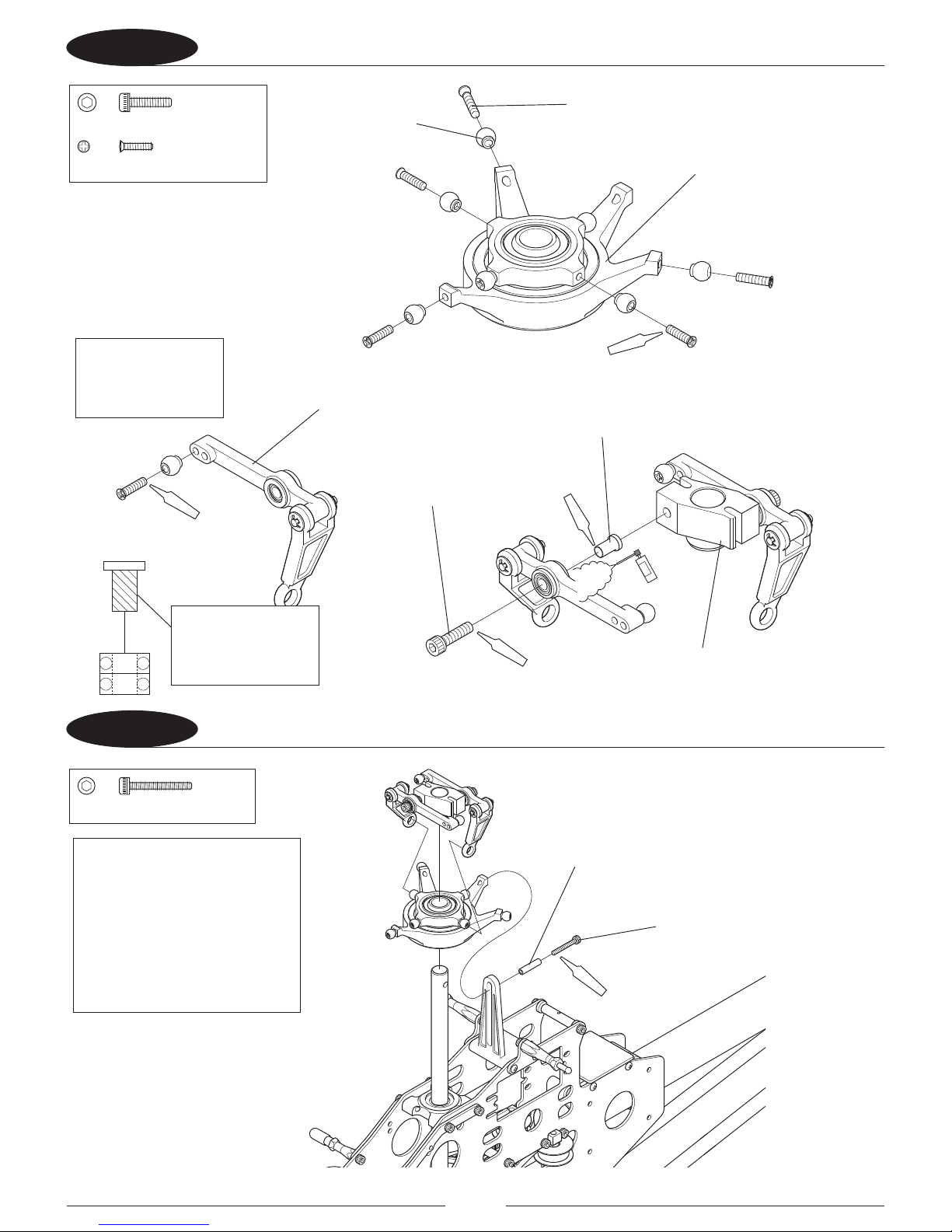
4-1 Assembling the Swashplate and
Washout Assembly ..............................................18
4-2 Attaching the Swashplate and
Washout Assembly ..............................................18
4-3 Assembling the Main Blade
Holder and Rotor Hub Part 1 ...........................19
4-4 Assembling the Main Blade Holder and
Rotor Hub Part 2 ...................................................19
4-5 Attaching the Seesaw ........................................20
4-6 Attaching the Seesaw Arm ...............................20
4-7 Attaching the Main Rotor Head ......................21
4-8 Attaching the Stabilizer Arm ...........................21
4-9 Attaching the Paddle Decals ...........................22
4-10 Attaching the Paddle ..........................................22
4-11 Installing Main Rotor Head Linkages ............23
5-1 Assembling the Motor and Motor Mount ...23
5-2 Attaching the Motor ........................................... 24
5-3A Installing Mini Servos Part 1.............................24
5-3B Installing Mini Servos Part 2............................. 25
5-4A Installing Standard Servos Part 1 ...................25
5-4B Installing Standard Servos Part 2 ...................26
5-5 Preparing the Servo Arms .................................26
Radio System Preparation ............................................ 27
Understanding CCPM Control Systems ...................28
Important CCPM Programming
Do’s and Don’ts ..................................................... 30
CCPM Software Initial Adjustments ..........................31
JR 12X Programming ......................................................32
JR X9303 2.4 and XP9303: Programming ................36
JR 7202 and Spektrum DX7se and DX7:
Programming ........................................................ 40
5-6 Installing the Servo Arms .................................. 44
5-7 Installing Swash Servo Linkages ....................45
5-8 Assembling the Tail Control Rod ....................46
5-9 Attaching the Tail Control Rod ........................46
6-1 Installing the Speed Controller .......................47
6-2 Installing the Receiver and Gyro ....................47
6-3 Fixing the Wiring .................................................. 48
6-4 Installing the Battery ..........................................48
6-5 Installing the Body ..............................................49
Basic Adjustment After Assembly .............................50
6-6 Balancing the Main Rotor Blades ...................51
6-7 Attaching the Main Rotor Blades ...................51
Leveling the Swashplate ............................................... 52
Pitch-to-Aileron Mixing Adjustment ........................53
Pitch-to-Elevator Mixing ............................................... 54
Tail Servo Adjustment .................................................... 55
Final Servo Adjustment and Radio Setup ............... 56
Pitch Range and Curve Settings ................................. 57
Pitch Adjustment Linkages .......................................... 58
Conrmation of Proper Blade Direction..................59
Final Preight Check .......................................................59
Blade Tracking Adjustment .......................................... 60
General Maintenance ..................................................... 61
Repair of Assemblies ......................................................62
Repair of Assemblies ......................................................63
Replacement Parts Listing ............................................ 64
Page 3

3
INTRODUCTION
KEY FEATURES
To say electric helis are everywhere these days is a bit of an understatement. Electric helicopter performance and
popularity is on a level now that is unprecedented in the history of RC. And with the demand for more power
and potential comes the demand for a heli platform that can handle it.
Enter the Vibe 500e. JR’s latest foray into electric helicopter design has the benet of drawing on years of glow
heli development, producing a platform built from the ground up to dominate. The design is all new, and was
conceived with one goal in mind—being the smoothest, most precise electric helicopter available. Features like
the belt-driven tail, aluminum head and tail assemblies plus more, make precision and smoothness a possible
reality. The result is a connection between you and your heli that feels like nothing you’ve ever own before.
• 120CCPM
• Belt-driventail
• Fullaluminumheadandtailassemblies
• Designedfor6SLi-Popower(2200or2600mAhThunderPowerorsimilar)
• DesignedforE-itePower251000Kvhighpowerhelimotorsystemforaggressive3Dperformance
• UsesE-ite60-AmpProESC
• Requires425–430mmmainblades
• Constantdriventailrotor
Page 4
4
PREASSEMBLY WARNING
RECOMMENDED RADIO SYSTEM
When rst opening your helicopter, you will notice that all of the parts are packaged and numbered to
coordinate with the assembly step numbers of this instruction manual. All small hardware (nuts, bolts, washers,
etc.) for each step is separated and packaged separately within the main parts bags. When beginning a section,
you will need to open only the bag with the corresponding number to the section you are going to start. It is
suggested that you place all of the hardware in an open container (e.g., coee can) during assembly so as not
to lose any of the small parts. It may also be helpful to familiarize yourself with the various sizes of screws, bolts,
nuts, etc., as illustrated in the appropriate assembly section before you begin assembly. At the end of each
assembly, in most cases, there should be no parts remaining.
NOTE: Your kit also includes JR® red and green threadlock. Unlike conventional U.S.-made
threadlock, JR red is the U.S. equivalent of blue. JR green is the equivalent of U.S. red.
Great care has been taken in lling the bags with the correct quantity of parts and hardware for each section.
However, occasionally mistakes do happen. In the event that you nd a parts shortage or are in need of
technical assistance, please contact your local JR Heli Division parts dealer or contact the Horizon Service Center
directly.
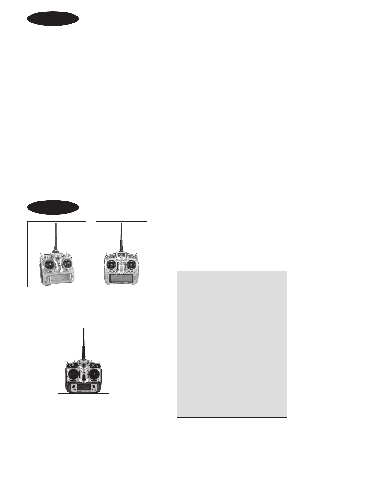
JR 12X 2.4
(JRP1200)
JR X9303 2.4
(JRP2925)
Spektrum DX7se
(SPM2731)
CCPM-Ready JR Radio Systems
Most current JR and Spektrum heli radio
systems (12X, XP9303, X9303 2.4, DX7se,
DX7 and DX6i) are equipped with 120° CCPM
electronics for use with JR CCPM machines.
Radios you may be ying now, like the X347,
X388S, XP783 and XP8103* have 120° CCPM
capability built in but require activation by
the Horizon Service Department. For details,
please call (877) 504-0233.
*Please note that many XP8103 systems
have the CCPM function already activated.
Please check with the Horizon Service
Center for details.
Spektrum is used with permission of
Bachmann Industries, Inc.
Page 5
5
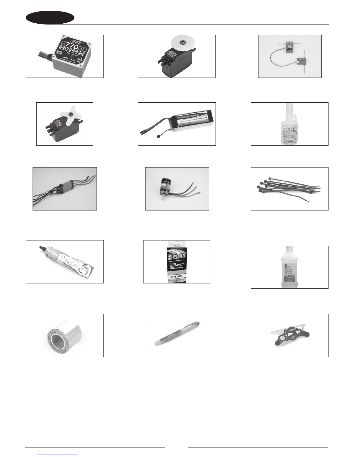
ITEMS REQUIRED TO COMPLETE ASSEMBLY
G770 3D Gyro (JRPG7703D)
E-ite Power 25 Heli BL
Outrunner Motor,1000KV
(EFLM4025H)
Oil Touch Pen
(JRP961296)
2200mAh–2600mAh
(6S Battery) (THP27006SP30)
PAAPT39
30-Minute Z-Poxy
3500G Gyro Servo (JRPG3500G)
PAAPT02
Zap-A-Gap CA+
Rubbing Alcohol
Nylon Wire Ties (ASC7709)
E-ite 60-AMP PRO SB
Brushless ESC (EFLA1060)
Double-Sided Servo Tape
(BRP7541)
DS3517 High-Speed Mini Servo
(x3)
Grease
Spektrum AR6200, AR7000 or JR
R921 Receiver
(SPMAR6200)
Pitch Gauge w/Case
JRP960326
Page 6
6
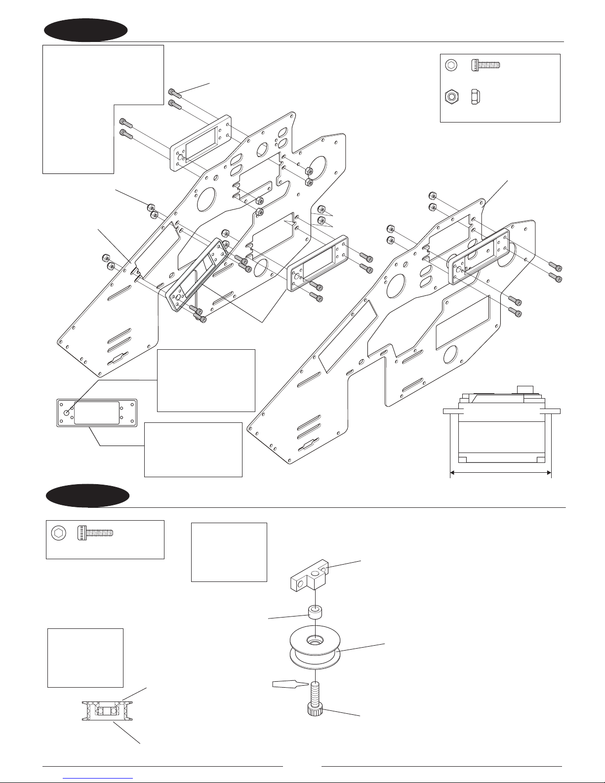
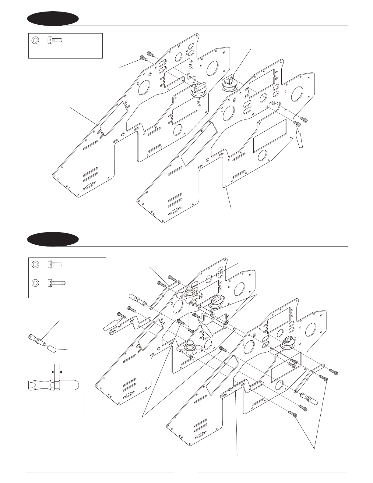
11A ATTACHING THE SERVO ADAPTERS
11B ASSEMBLING THE GUIDE ROLLER
SocketHeadBolt,M3×10
………×2
SocketHeadBolt,M2.6×8
………×16
NylonLockNut,M2.6
………………×16
Red
(×2)
Socket Head Bolt, M2.6 x 8 (16 Pcs)
Socket Head Bolt, M3 x 10 (2 Pcs)
Nylon Lock Nut, M2.6 (16 Pcs)
Guide Roller Block (2 Pcs)
Guide Roller (2 Pcs)
Top
Bottom
Guide Roller Spacer (2 Pcs)
Main Frame L
Main Frame R
Mini Servo
38.5mm
Servo Adapters (4 Pcs)
Prepare 2 sets of
the Guide Roller
assembly.
Note the proper
direction of the
Guide Roller.
Install the servo
adapter in the direction
shown noting the
direction of the hole in
the adapter.
Note: Either Mini Servos
such as the DS3517 or
Standard Servos such as the
DS821 can be installed. If
using Mini Servos, install the
servo adapters
as shown. If
using Standard
Servos, skip
ahead to step
1-1B.
The at edge of the
adapter should be
installed toward the
frame.
Page 7
7
12 ATTACHING THE GUIDE ROLLER
13 ATTACHING THE BEARING CASE AND FRAME SUPPORT
SocketHeadBolt,M2.6×6
……………×4
SocketHeadBolt,M2.6×8
……………×6
SocketHeadBolt,M2.6×10
……………×8
Red(×8)
Red (×6)
Red
(×4)
Socket Head Bolt, M2.6 x 6 (4 Pcs)
Socket Head Bolt, M2.6 x 8 (6 Pcs)
Socket Head Bolt,
M2.6 x 10 (8 Pcs)
Guide Roller Assembly (2 Pcs)
SG Twist Support, Upper (2 Pcs)
Absorber Post(2 Pcs)
Absorber Cap (2 Pcs)
3mm
HG Bearing Case (2 Pcs)
HG Cross Member (2 Pcs)
Frame Support Plate, Lower (2 Pcs)
Main Frame R
Main Frame L
Prepare 2 sets of
the Absorber Post
assembly.
Page 8
8
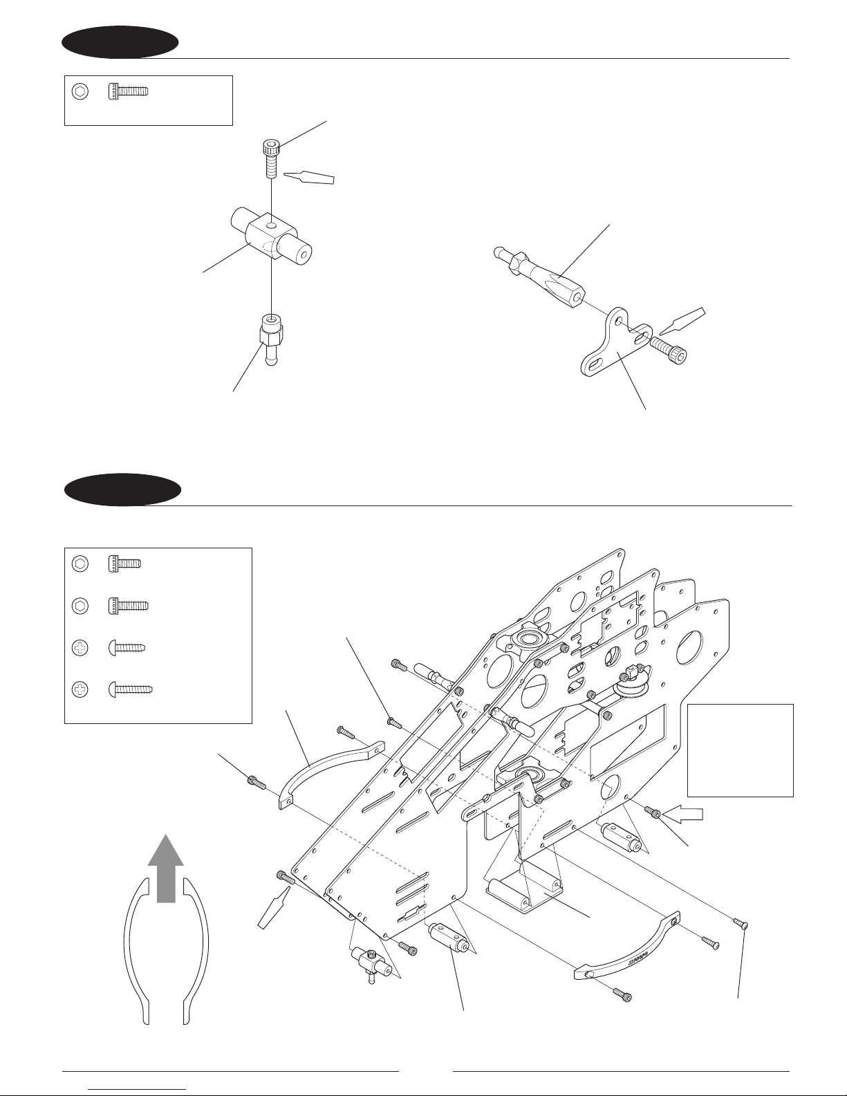
14 ATTACHING THE BODY CATCH
15 ATTACHING THE FRAME BRIDGE
SocketHeadBolt,M2.6×8
…………×3
SocketHeadBolt,M2.6×8
……………×4
SocketHeadBolt,M2.6×6
……………×2
……………×2
Self-TappingScrew,M2.6×8
……………×2
Self-TappingScrew,M2.6×10
Red (×2)
Red
Temp.
(×4)
Red(×2)
Socket Head Bolt, M2.6 x 8 (3 Pcs)
Socket Head Bolt, M2.6 x 8 (4 Pcs)
Socket Head Bolt,
M2.6 x 6 (2 Pcs)
Frame Stando
Block
Self-Tapping Screw, M2.6 x 10 (2 Pcs)
Self-Tapping Screw,
M2.6 x 8 (2 Pcs)
Frame Bridge R/L
Brace Mount(2Pcs)
Front
Body Catch 23mm (2 Pcs)
SG Body Mount Plate (Rear) (2 Pcs)
Body Catch 4mm
Body Catch Mount
Do not fully
tighten M2.6 x 6
screws until the
landing gear is
installed later.
Page 9
9
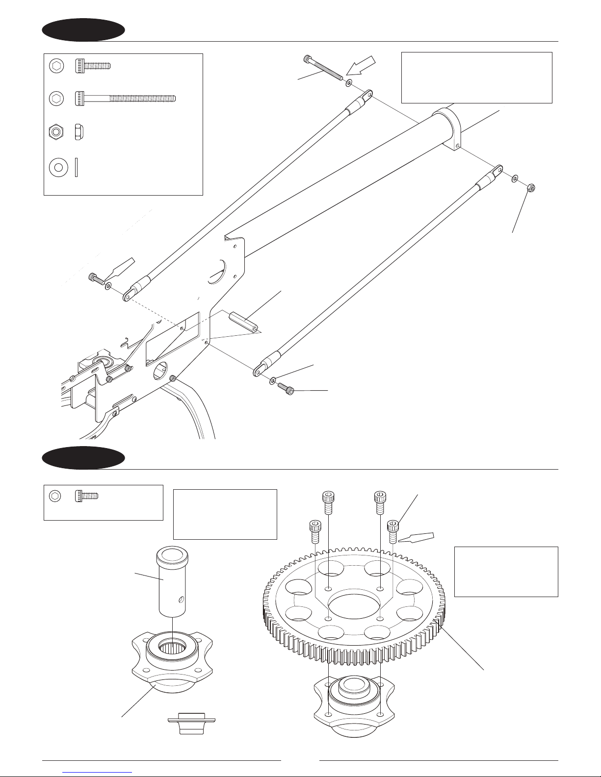
16 ATTACHING THE RADIUS SUPPORT
17 ATTACHING THE BATTERY MOUNT
Soft(×6)
Soft(×6 )
Red(×4)
SocketHeadBolt,M2.6×8
……………×4
……………×4
Self-TappingScrew,M2.6×10
……………×6
FlatHeadScrew,M2.6×5
SocketHeadBolt,M2.6×6
…………×6
Socket Head Bolt, M2.6 x 8 (4 Pcs)
Socket Head Bolt, M2.6 x 6 (6 Pcs)
Self-Tapping Screw, M2.6 x 10 (4 Pcs)
Flat Head Screw, M2.6 x 5 (6 Pcs)
Brace Mount (3 Pcs)
Carbon Battery Mount
HG Cross Member 25mm (2 Pcs)
Radius Support
Hook and Loop Strap M (2 Pcs)
Page 10
10
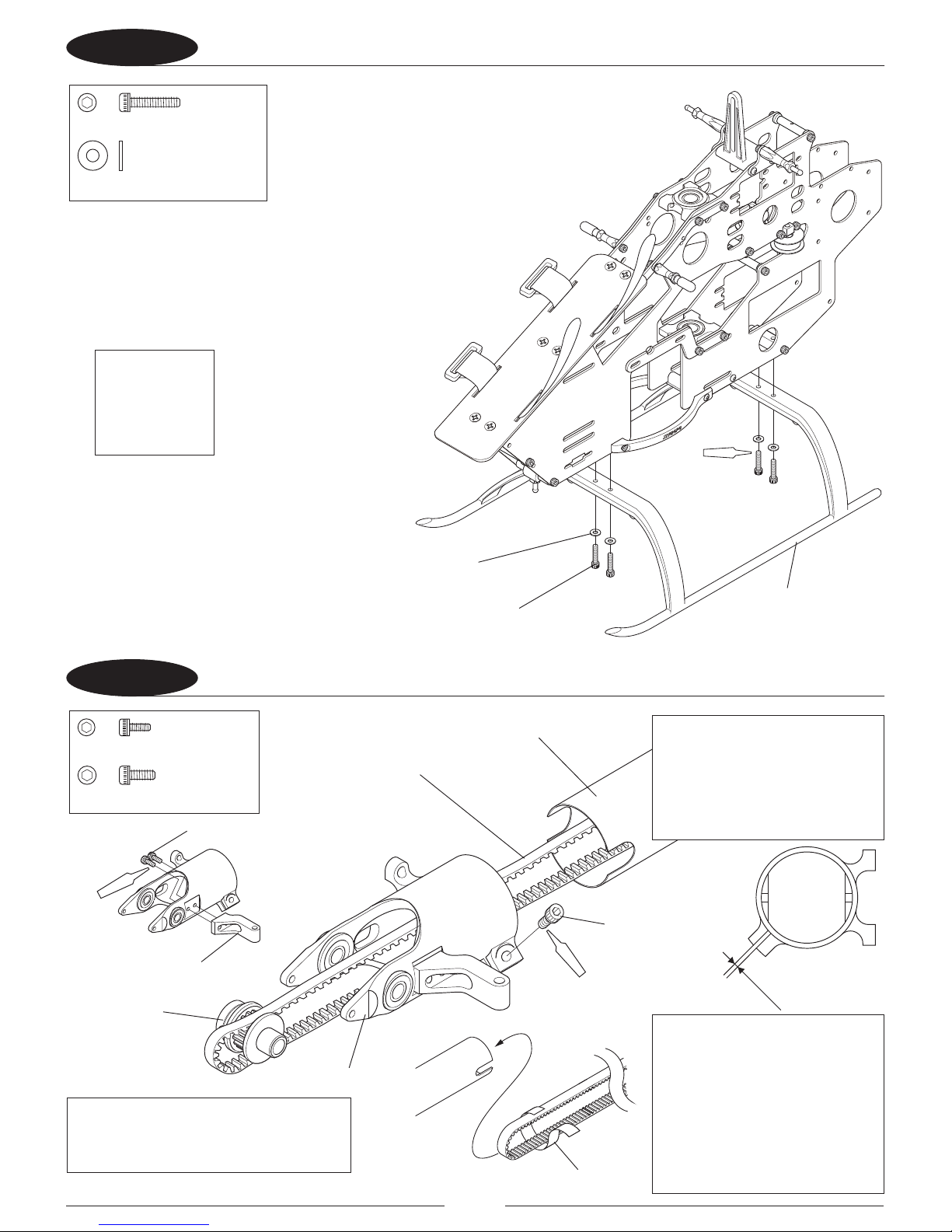
18 ATTACHING THE LANDING GEAR
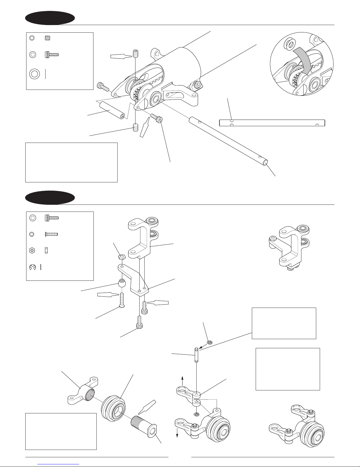
21 ATTACHING THE TAIL PULLEY CASE
SocketHeadBolt,M2.6×12
………×4
FlatWasher,M2.6
…………………×4
Soft(×4 )
SocketHeadBolt,M2×5
……………×2
SocketHeadBolt,M2.6×6
……………×1
Red
(×2)
Red
0.5mm
Socket Head Bolt, M2.6 x 12 (4 Pcs)
Socket Head Bolt,
M2.6 x 6
Socket Head Bolt, M2 x 5 (2 Pcs)
Tail Pitch Control Base
Clear Tape
Tail Pulley Case
Tail Pulley
Tail Drive Belt
Tail Boom L470
Flat Washer, M2.6 (4 Pcs)
Landing Gear
Note: After the
landing gear is
installed, fully
tighten the bolts
left loose from
Step 1-5.
Note: To easily pull the tail drive
belt through the tail boom, wrap a
small piece of tape around the belt
using great care to not pinch the
belt at the bend and weakening
the belt. Caution: If the belt is bent
or kinked during assembly it will
damage the belt and cause a failure
resulting in loss of tail control.
Note: Tighten the M2.6 x 6 socket
head bolt carefully when tightening
on the Tail Boom, the Tail Boom will
be damaged if overtightened. There
should be a gap remaining in the
clamp when fully tightened.
Note: The notched end of the tail boom
installs into the Tail Pulley Case. Insert the
Tail Boom as deeply as possible.
Page 11
11
22 ATTACHING THE TAIL OUTPUT SHAFT
23 ASSEMBLING THE TAIL PITCH CONTROL LEVER
Red
(×2)
Red
(×2)
……………×2
Setscrew,M3×4
SocketHeadBolt,M2×6
…………×2
Polysliderwasher4.1×6.5×0.13
………………×2
SocketHeadBolt,M2×6
…………×2
FlatHeadScrew,M2×8
…………×1
Nut,M2
………………×1
ERetainingRing,M1.5
………×5(1spare)
Red
Red (×2)
Red
Tail Case Cross Member
Joint Ball
Nut, M2
Tail Output Shaft
Tail Pulley Side
Setscrew, M3 x 4 (2 Pcs)
Socket Head Screw, M2 x 6 (2 Pcs)
Flat Head Screw, M2 x 8
Tail Slide Ring
Tail PC Plate
Tail PC Link (2 Pcs)
Tail Pitch Control Arm
HG Tail PC Link Pin(2 Pcs)
Tail Pitch Control Lever
E Retaining Ring, M1.5 (4 Pcs)
Tail Slide Ring Sleeve
Socket Head Bolt, M2 x 6 (2 Pcs)
If the Tail Pulley has too much play (to
the left and right) install the included
Polyslider washers to adjust. Install
the washers as necessary to eliminate
any free play in the tail pulley.
Note: Be certain the
e-clips are fully installed
in the groove in the pin.
Note: Be sure to note the
proper tightening direction
for the Tail Slide Ring Sleeve,
it is reverse threaded.
Note: Be sure to install
the Tail PC Link in the
correct direction. The side
with the circular marks
should be in the direction
of the arrow.
Page 12
12
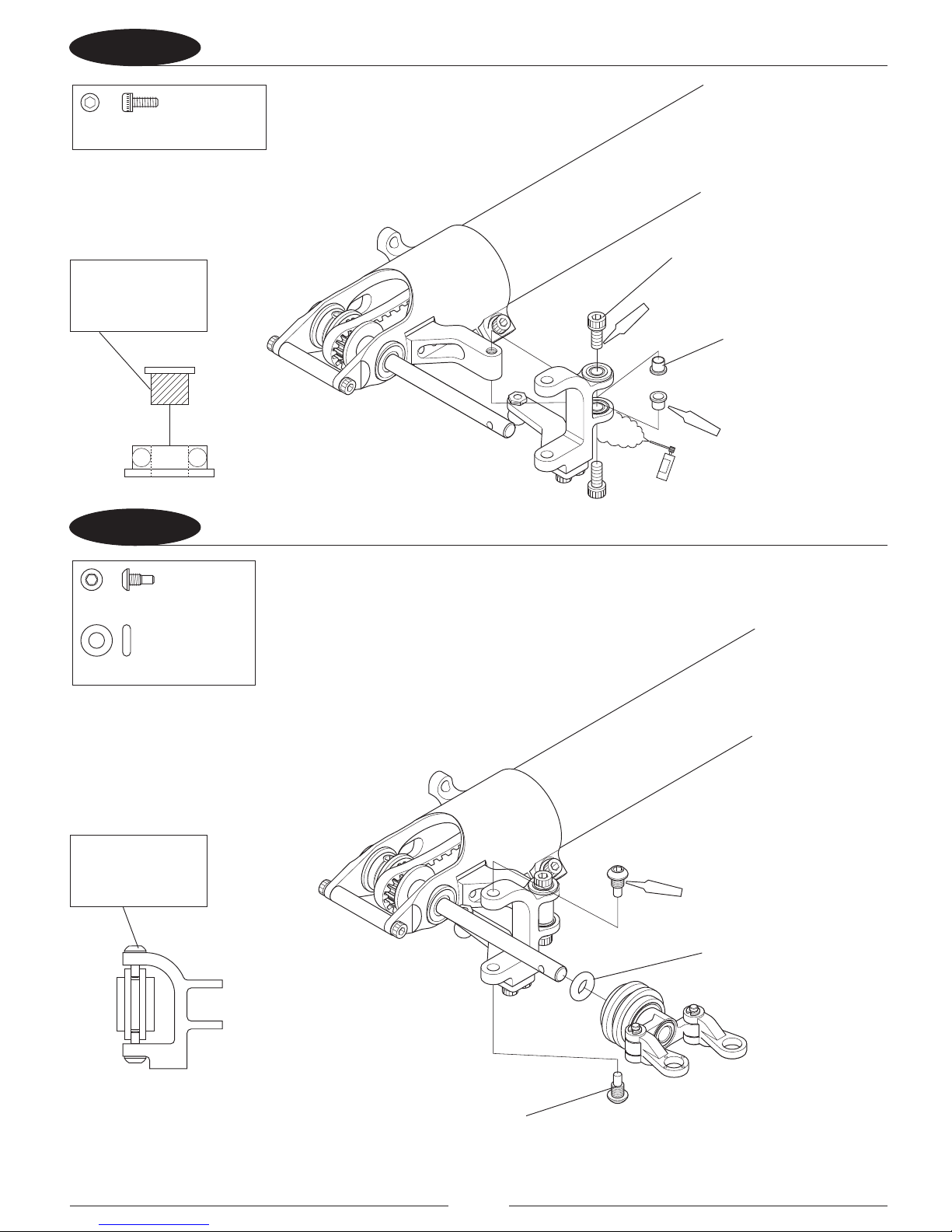
24 ATTACHING THE TAIL PITCH CONTROL LEVER 1
25 ATTACHING THE TAIL PITCH CONTROL LEVER 2
SocketHeadBolt,M2.6×6
……………×2
Red
(×2)
Red
(×2)
Degrease
Red
(×2)
TailPCSlideBolt
…………×2
O-Ring3.8×7.6×1.9(90°)
……………×1
Socket Head Bolt, M2.6 x 6 (2 Pcs)
O-ring 3.8 x 7.6 x 1.9 (90°)
Tail PC Slide Bolt (2 Pcs)
Tail Pitch Control
Bearing Collar(2 Pcs)
Apply a thin and
even layer of red
threadlock to adhere
Tighten the Tail PC
Slide Bolts, tting
them in the groove
in the tail slide ring.
Page 13

13
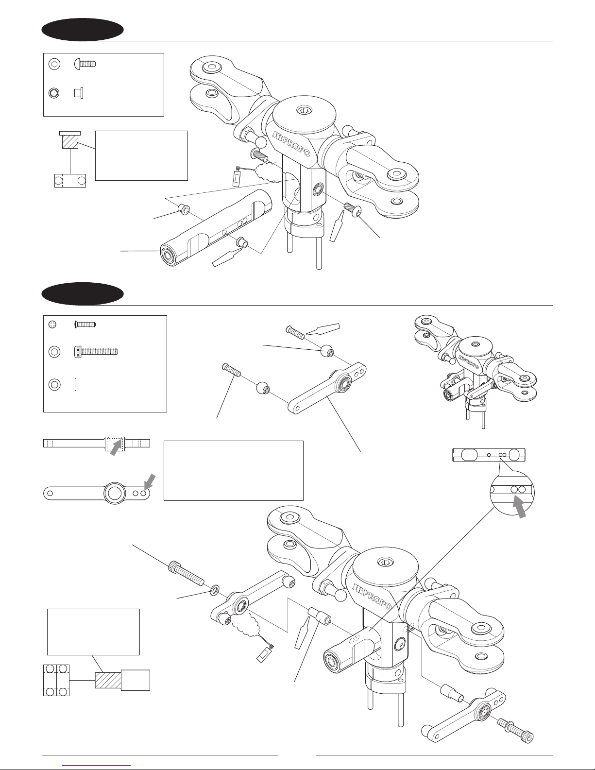
26 ATTACHING THE TAIL ROTOR GRIP
27 ATTACHING THE TAIL ROTOR BLADE
FlatHeadScrew,M2×7
……………×2
SocketHeadBolt,M3×10
………×2
Washer,03×4.5×0.4
…………………×2
………………×1
Setscrew,M3×4
O-Ring3.5×5.5×1
…………………×2
Red(×2)
Red
SocketHeadBolt,M2.6×12
………×2
NylonLockNut,M2.6
…………………×2
Red
(×2)
O-ring 3.5 x 5.5 x 1 (2 Pcs)
Washer, 3 x 4.5 x .04 (2 Pcs)
Socket Head Bolt, M3 x 10 (2 Pcs)
Flat Head Screw, M2 x 7 (2 Pcs)
Nylon Lock Nut, M2.6 (2 Pcs)
Long Tail Rotor Blade (2 Pcs)
Socket Head Bolt, M2.6 x 12 (2 Pcs)
Joint Ball (2 Pcs)
Tail Rotor Grip (2 Pcs)
Setscrew, M3 x 4
Tail Center Hub
Note: Clamp the Tail Rotor Blades
uniformly to an extent that the tail
blade will move back and forth
when a slight force is applied to
them by hand.
Page 14
14
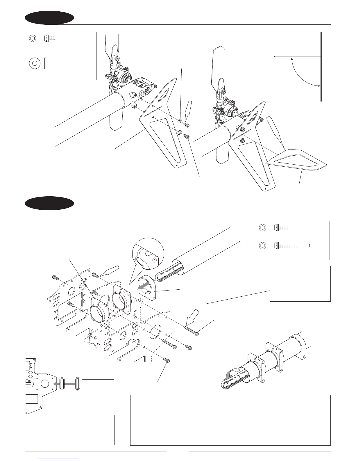
28 ATTACHING THE HORIZONTAL STABILIZER AND VERTICAL FIN
29 INSTALLING THE TAIL BOOM
Temp.
(×2)
Red (×6)
FlatWasher,M2.6
…………………×2
SocketHeadBolt,M2.6×4
……………×2
90°
CA
Red
(×2)
SocketHeadBolt,M2.6×6
……………×6
SocketHeadBolt,M2.6×20
…×2
Socket Head Bolt,
M2.6 x 4 (2 Pcs)
Flat Washer, M2.6 (2 Pcs)
HG Tail Boom Holder (2 Pcs)
Tail Support Clamp
Horizontal Stabilizer
Vertical Fin
Socket Head Bolt, M2.6 x 20 (2 Pcs)
Socket Head Bolt, M2.6 x 6 (6 Pcs)
Note: Do not fully
tighten the M2.6x20
socket head bolts until
the belt tension is set in
a later step.
Note: Insert the tail boom as far
forward as it will go into the tail
boom holders; belt tension will be set
later in the assembly.
Note: Pay close attention to the direction of rotation of the belt. With the belt
installed as shown, sight down the tube to ensure that the belt is not twisted down
the length of the boom, then rotate the belt 90 degrees in the direction of the arrow to
ensure the tail blades rotate the proper direction and the belt is not twisted or kinked.
The tail blade rotation direction will be veried later in step 3-5.
Caution: If the belt is twisted or kinked it will cause premature wear and failure of the
belt which will cause loss of tail control.
Page 15
15
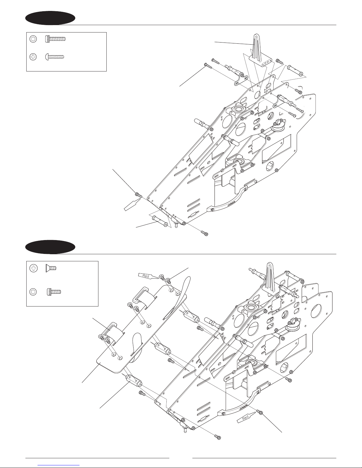
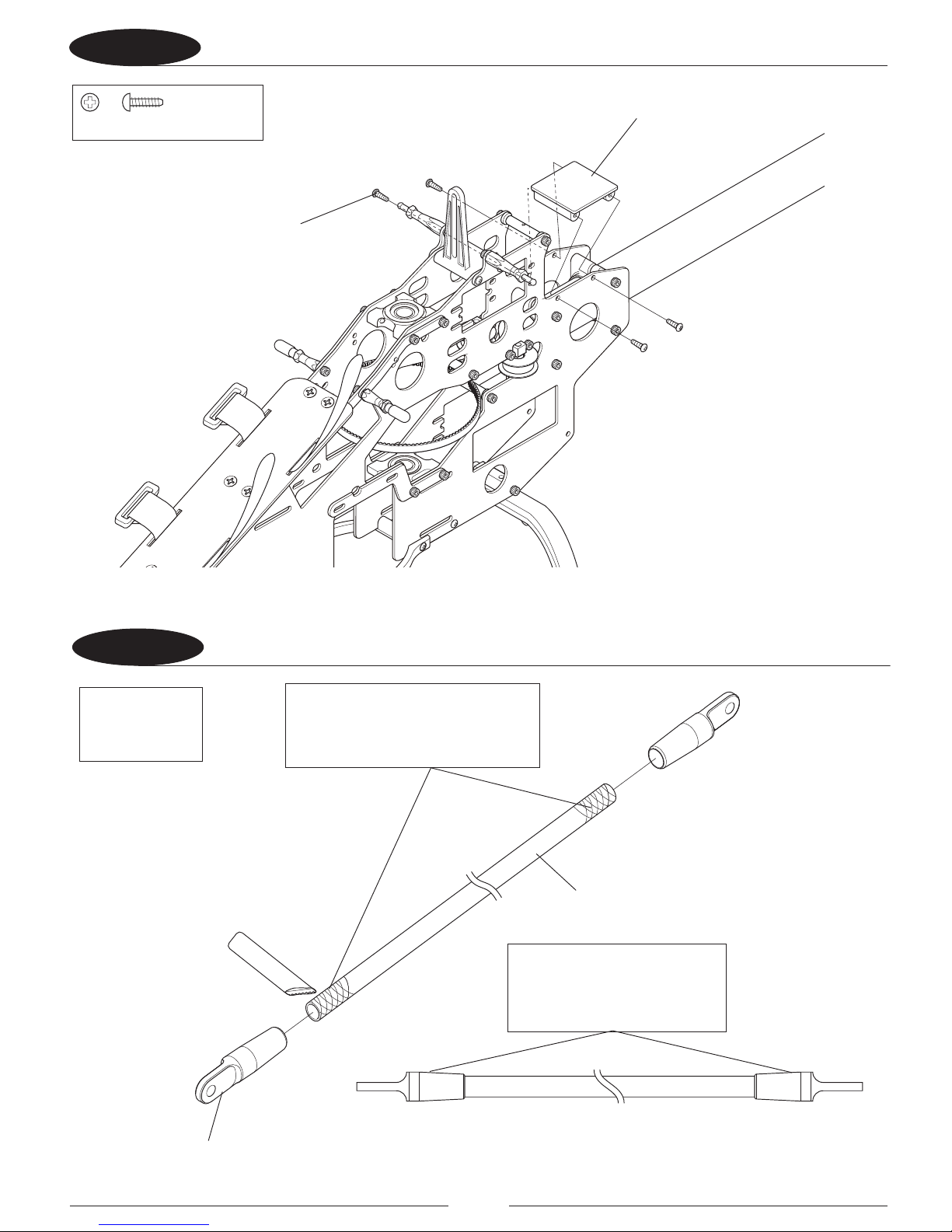
31 ATTACHING THE GYRO MOUNT
32 ASSEMBLING THE BOOM SUPPORTS
EPOXYA+B(×)4
Self-TappingScrew,2.6×8
…………×4
Self-Tapping Screw, M2.6 x 8 (4 Pcs)
Boom Support End (4 Pcs)
Carbon Tail Boom Support L275(2 Pcs)
Gyro Mount
Note: Prior to assembly, lightly sand
the ends of the carbon boom supports
to ensure a good bond with the boom
support ends.
Note: Adhere the Boom Support
ends carefully in alignment with
each other as shown.
Assemble 2 Boom
Supports
Page 16
16
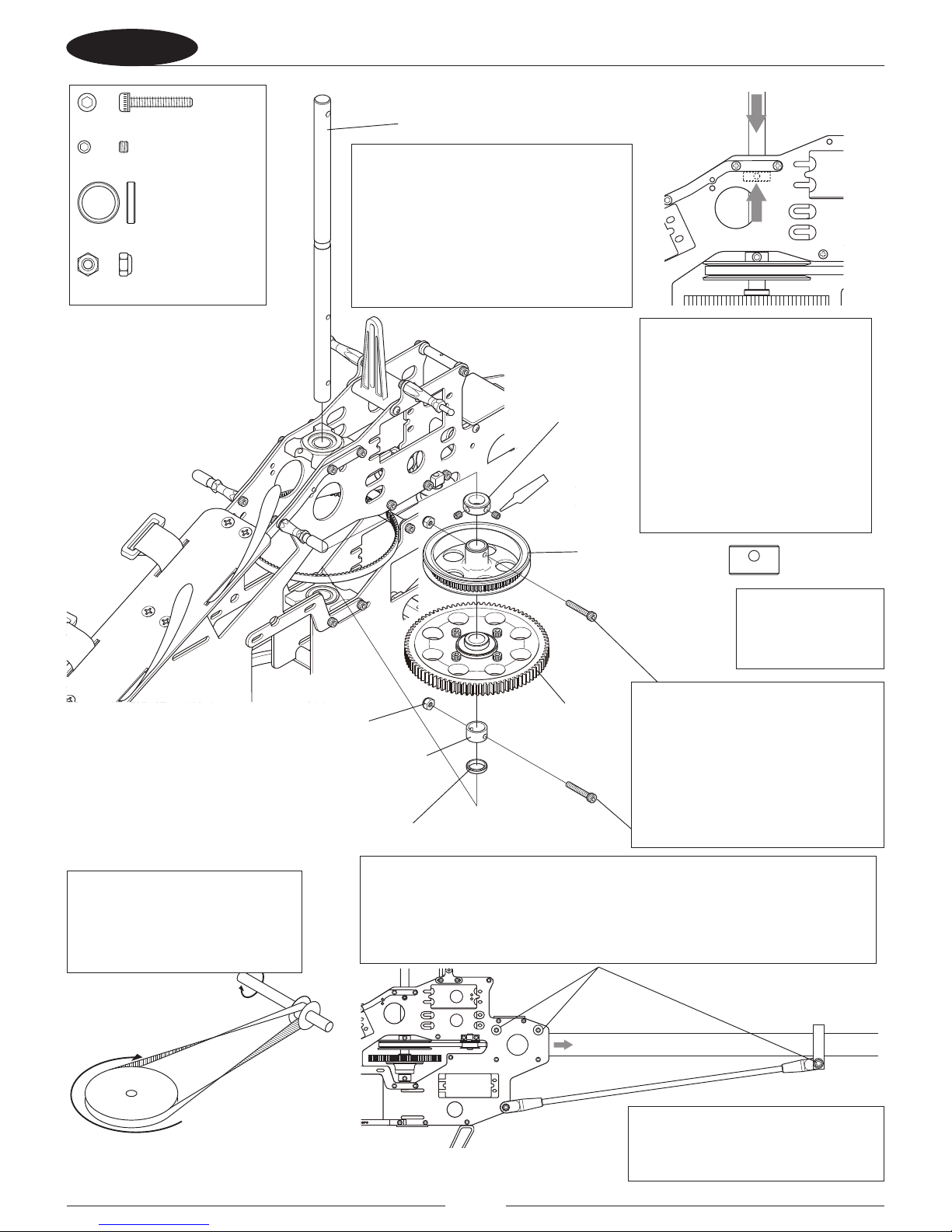
33 ATTACHING THE BOOM SUPPORTS
34 ASSEMBLING THE MAIN DRIVE GEAR
Red
(×2)
Temp.
SocketHeadBolt,M2.6×6
…………×4
FlatWasher,M3
……………………………×4
NylonLockNut,M3
……………………………×1
SocketHeadBolt,M3×35
…×1
SocketHeadBolt,M3×10
……………………×2
Red (×4)
Socket Head Bolt,
M3 x 35
Socket Head Bolt, M3 x 10 (2 Pcs)
Socket Head Bolt, M2.6 x 6 (4 Pcs)
Cross Member 25mm
(Black)
Nylon Lock Nut, M3
Flat Washer, M3 (4 Pcs)
Autorotation Sleeve
T85 Main Drive Gear
Autorotation Unit
Top
Bottom
Note: Do not fully tighten M3 x 35
socket head bolt at this time. This
bolt will be tightened in step 3-5
when the belt tension has been set.
Note: Insert the
Autorotation Sleeve into
the Autorotation Unit.
Note: Tighten the bolts
for the main gear equally
to prevent warping.
Page 17
17
35 ATTACHING THE MAIN DRIVE GEAR FRONT PULLEY
Soft (×2)
SocketHeadBolt,M2.6×15
………×2
NylonLockNut,M2.6
…………………×2
…………………×2
Setscrew,M3×3
MainShaftSpacer
…………………×1
Main Shaft
Main Shaft Collar
Front Pulley
Main Drive Gear
Assembly
Autorotation Collar
Nylon Lock Nut, M2.6 (2 Pcs)
Main Shaft Spacer
Note: After installing the Front
Pulley and Auto Rotation Assembly,
push down on the Main Shaft, and
pull up on the Main Shaft Collar
until it is against the top Main
Shaft Bearing Block. Tighten the
M3 x 3 Setscrews in the Collar
while holding the Main Shaft Collar
against the Bearing Block and the
Main Shaft pressed down against
the lower Main Shaft Bearing Block.
Note: The proper
direction to install the
Auto Rotation Collar is
as shown.
Note: If the Tail Boom is stuck and
cannot easily be moved, loosen the Gyro
Mount attachment screws.
Check that the Tail Drive Belt
direction rotation is correct as shown
and there are no twists in the belt.
Ensure the Tail Blades rotate in the
proper direction prior to ight.
Note: After the direction of the Tail Drive Belt has been conrmed, set the belt
tension. The belt tension should be set by pulling out on the Tail Boom so that
the belt will remain in contact with the Guide Roller when pressed with a nger
between the Front Pulley and Guide Roller. When the belt tension is set properly,
tighten the bolts left loose previously in step 3-3.
Note: After installing the Main Shaft
through the bottom Main Shaft Bearing
Block, install the M2.6 x 15 socket head
bolts through the Front Pulley and
Main Shaft and then through the Auto
Rotation Assembly and Auto Rotation
Collar by aligning the holes in each
assembly with the corresponding holes
in the Main Shaft.
Note: Install the Main Shaft in the proper
direction as shown through the top bearing
block, then through the Main Shaft Collar,
Front Pulley, Main Drive Gear Assembly,
Auto Rotation Collar, Main Shaft Spacer, and
nally the bottom Main Shaft Bearing Block.
Be sure to loop the Tail Drive Belt around
the Front Pulley in the direction shown
previously in step 2-9.
Page 18
18
41 ASSEMBLING THE SWASHPLATE AND WASHOUT ASSEMBLY
42 ATTACHING THE SWASHPLATE AND WASHOUT ASSEMBLY
Red(×7)
Red (×2)
Red(×2)
Degrease
Red (×2)
SocketHeadBolt,M2×15
……×1
Red
FlatHeadScrew,M2×8
……………×9
SocketHeadBolt,M2.6×10
…………×2
Flat Head Screw, M2 x 8 (9 Pcs)
Socket Head Screw,
M2.6 x 10 (2 Pcs)
Socket Head Bolt, M2 x 15
120° Swashplate Assembly
Washout Arm Collar (2 Pcs)
Washout Arm (2 Pcs)
Washout Base
Swash Pin
Joint Ball (9 Pcs)
Note: Assemble
2 Washout Arm
Assemblies
Apply a light even
coat of red threadlock
to uniformly adhere
Note: Slide the Swashplate onto
the Main Shaft. Install the M2 x 15
and Swash Pin onto the Swashplate
going through the Radius Support
as shown. Next install the Washout
Assembly onto the Main Shaft and
install the Washout links onto the
Joint balls on the Swashplate as
shown.
Page 19

19
43 ASSEMBLING THE MAIN BLADE HOLDER AND ROTOR HUB 1
44 ASSEMBLING THE MAIN BLADE HOLDER AND ROTOR HUB 2
Red
Red(×2)
SocketHeadBolt,M3×6
…………×1
O-Ring5.2×10.4×2.6
…………×4
SocketHeadBolt,M3×10
………×2
FlatWasher,M3
………………×2
GripSpacer
…×2
SpindleWasher
…×2
Red (×2)
(×2)
Grease
Socket Head Bolt, M3 x 6
Socket Head Bolt,
M3 x 10 (2 Pcs)
Head Button
O-ring 5.2 x 10.4 x 2.6 (4 Pcs)
Main Blade Holder Assembly (2 Pcs)
Ball Arm (2 Pcs)
Main Rotor Hub
Smaller I.D.
Larger I.D.
Spindle Shaft
Grip Spacer (2 Pcs)
Thrust Bearing T5-10 (2 Pcs)
Spindle Washer (2 Pcs)
Flat Washer, M3 (2 Pcs)
Parts Bags 1=50°
2=70°
For 3D performance
install 70° O-rings
Note:
Assemble 2
Main Blade
Holder sets.
Note: Apply a small amount of Thrust Bearing
Grease to the Thrust Bearing
Note: If it is dicult to install the Spindle Shaft
through the O-ring dampeners, apply a small
amount of O-ring lubricant.
Note: The larger and smaller inner diameter Thrust
Bearing must be installed as shown.
Install the thrust BB CAGE toward the Main Shaft,
exposed balls to the Blade side of the grip. (The
thrust race will keep grease in, and positioning
the cage this way will prevent any possible cage
deformation from balls jamming on the cage that will
be thrown outward during use.)
Page 20
20
45 ATTACHING THE SEESAW
46 ATTACHING THE SEESAW ARM
ButtonHeadBolt,M2.5×6
……………×2
SeesawcenterCollar
………………×2
Degrease
Red(×2)
Red(×2)
Red (×4 )
Red(×2)
Degrease
FlatHeadScrew,M2×8
……………×4
SocketHeadBolt,M2.6×14
………×2
FlatWasher,2.6×4.5×0.5
…………………×2
Seesaw Center Collar (2 Pcs)
Joint Ball (4 Pcs)
Flange
Inner Hole
Flat Head Screw, M2 x 8 (4 Pcs)
Socket Head Bolt, M2.6 x 14 (2 Pcs)
Washer, 2.6 x 4.5 x 0.5 (2 Pcs)
Seesaw Arm Collar (2 Pcs)
Button Head Bolt, M2.5 x 6 (2 Pcs)
Seesaw Assembly
3D
Seesaw Arm(2 Pcs)
Apply a light, even
coat of red threadlock
to uniformly adhere.
Apply a light, even
coat of red threadlock
to uniformly adhere.
Note: The Seesaw Arm is installed
with the bearing retaining ange
toward the Seesaw Arm. For 3D
ight attach the joint ball to the
outer hole.
Page 21
21
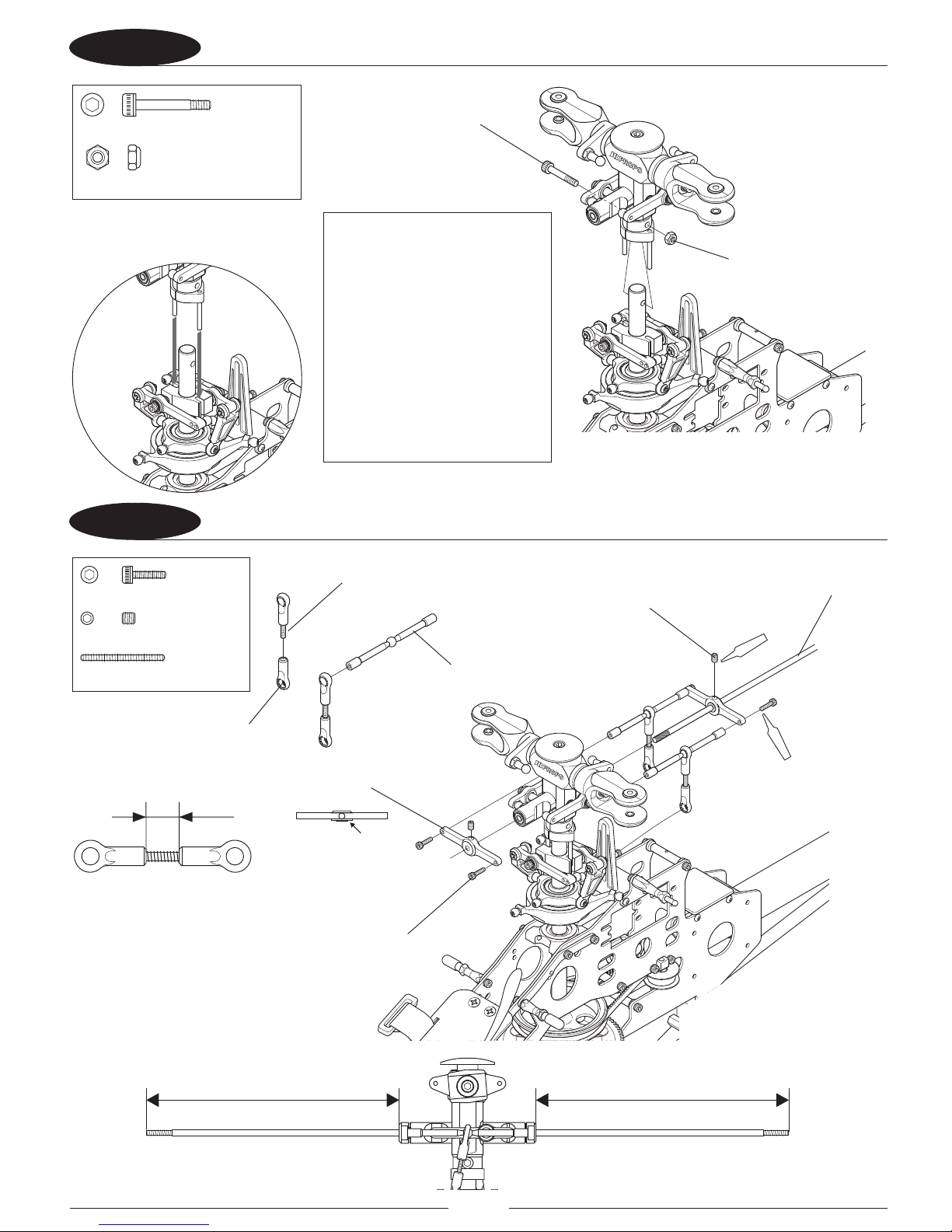
47 ATTACHING THE MAIN ROTOR HEAD
48 ATTACHING THE STABILIZER ARM
SpecilSocketHeadBolt,M3×18
…………×1
NylonLockNut,M3
………………………×1
137mm A=B
A B
SocketHeadBolt,M2×8
………×4
ScrewRod,M2.3×20
………×2
……………×2
Setscrew,M3×4
8mm
Red (×2 )
Red (×4)
Nylon Lock Nut, M3
Flybar 340mm
Setscrew, M3 x 4 (2 Pcs)
Screw Rod, M2.3 x 20 (2 Pcs)
Universal Link S (4 Pcs)
Stabilizer Arm A (2 Pcs)
This side to inside.
Socket Head Bolt, M2 x 8 (4 Pcs)
Stabilizer Arm B (2 Pcs)
Special Socket Head Bolt, M3 x 18
Note: Be certain that the washout
pins engage in the slots in the
Washout Base to ensure the phase
is correct.
Caution: Be certain to check that
the washout pins remain in the
slots in the Washout Base prior to
every ight. If the washout pins
are not engaged properly in the
Washout Base, the CCPM controls
will be out of phase, causing
incorrect cyclic response in ight
and will potentially cause a crash.
Page 22
22
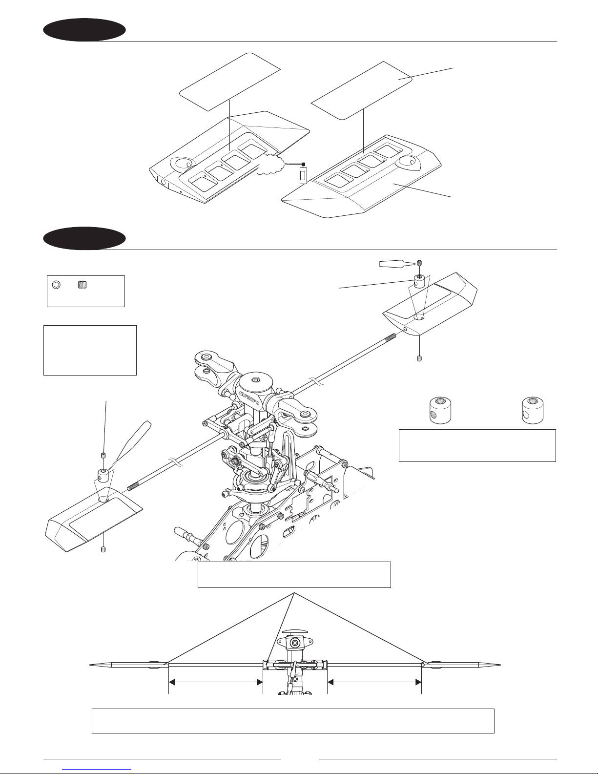
49 ATTACHING THE PADDLE DECALS
410 ATTACHING THE PADDLE
111.5mm
A
A=B
B
Degrease
Red
(×4)
(×2)
CAG
……×4
Setscrew,M3×4
Setscrew, M3 x 4 (4 Pcs)
This side to inside.This side to outside.
Paddle Stopper (2 Pcs)
Paddle (2 Pcs)
Paddle Decal (4 Pcs)
Install the paddles so they are even and parallel
with each other and the ybar cage.
Note: Ensure that A and B are equal in length.
Apply a small amount
of CA glue when
installing the Paddle
Stopper.
Note: Install the threaded side of the
Paddle Stopper to the outside.
Page 23
23
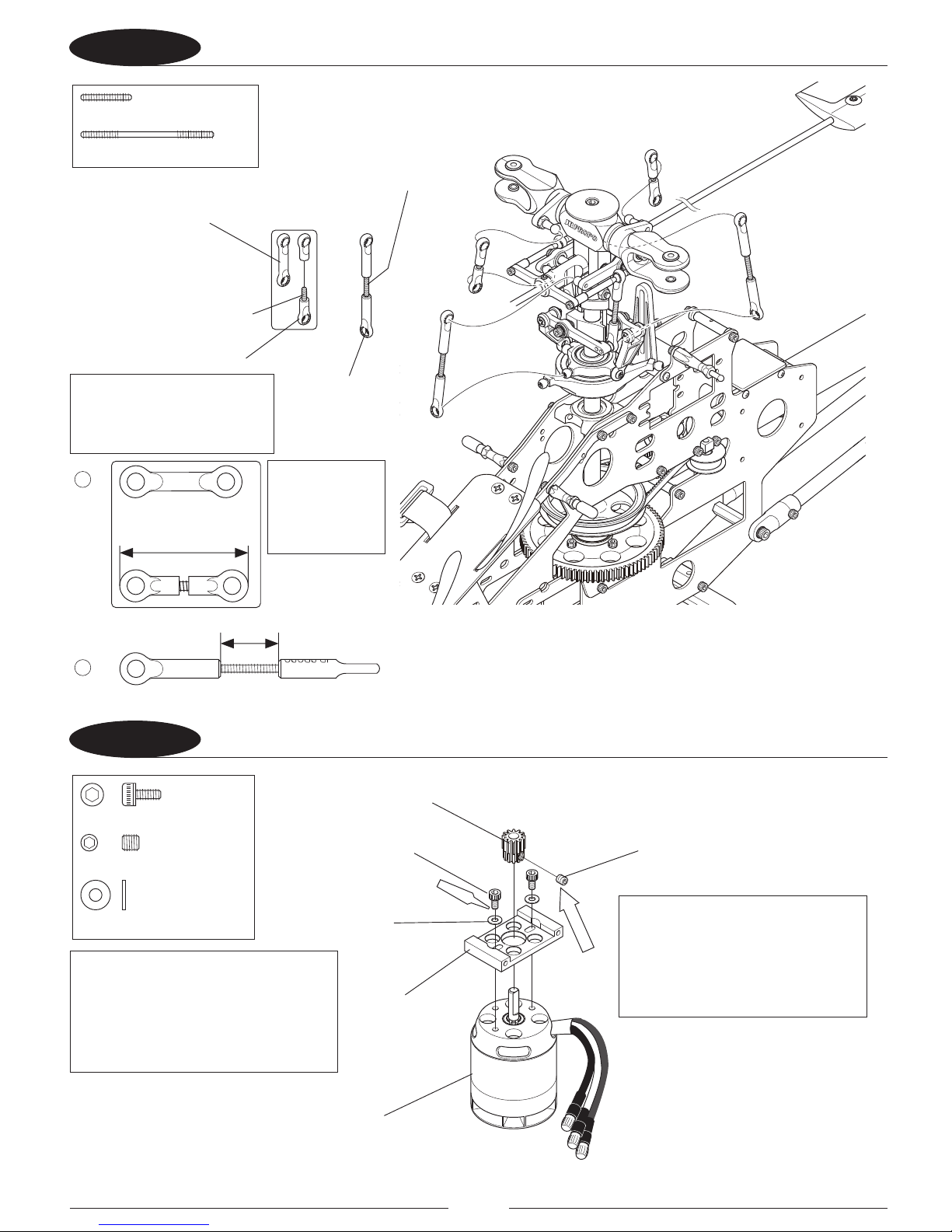
411 INSTALLING MAIN ROTOR HEAD LINKAGES
51 ASSEMBLING THE MOTOR AND MOTOR MOUNT
ScrewRod,M2.3×12
………………×2
ScrewRod,M2.3×30
…×2
JRPROPO
14mm
31mm
A
or
B
JRPROPO
SocketHeadBolt,M3×6
…………×2
FlatWasher,M3
………………×2
……………×1
Setscrew,M4×4
Temp
Red
(×2)
Double Link A (2 Pcs)
A
A
B
B
Screw Rod, M2.3 x 12 (2 Pcs)
Screw Rod, M2.3 x 30 (2 Pcs)
Setscrew, M4 x 4
Motor Mount
Motor (not included), E-ite
Power 25 Heli Outrunner Motor
(EFLM4025H)
T12 or T13 Pinion
Socket Head Bolt,
M3 x 6 (2 Pcs)
Flat Washer
M3 (2 Pcs)
Cut Universal Link (4 Pcs)
Universal Link (4 Pcs)
Parts Bags
T12 Pinion ③
T13 Pinion ④
If a replacement Universal Link
S is purchased for repair, cut it
by 3mm for this assembly.
Note: For 3D
ight, use the cut
Universal Link S
for rod A.
Note: Install the T12 pinion gear for sport
3D ight. Install the T13 pinion gear for
aggressive 3D performance. Using the
T13 pinion will result in less ight time
per charge, but higher power for more
aggressive performance.
Note: Do not fully tighten Setscrew,
M4 x 4 at this time. Fully tighten later
when the proper height position on
the Motor Shaft to line up with the
Main Gear is determined.
Page 24

24
52 ATTACHING THE MOTOR
53A INSTALLING MINI SERVOS PART 1
Red (×4)
FlatWasher,M2.6
…………………×4
SocketHeadBolt,M2.6×10
…………×4
22
…………×12
Self-TappingScrew,M2.6×10
FlatWasher,M2.6
…………………×12
Self-Tapping Screw,
M2.6 x 10 (12 Pcs)
Swash Servo L
Flat Washer,
M2.6 (12 Pcs)
Rudder/Tail Servo
Swash Servo F
Flat Washer, M2.6 (4 Pcs)
Socket Head Bolt, M2.6 x 10 (4 Pcs)
Note: Either Mini Servos
such as the DS3517 or
Standard Servos such
as the DS821 can be
installed. Follow the
directions for the type
you will install.
Note: Align pinion
gear of motor with
spur gear as shown.
Page 25

25
53B INSTALLING MINI SERVOS PART 2
54A INSTALLING STANDARD SERVOS PART 1
22
…………×12
Self-TappingScrew,M2.6×12
FlatWasher,M2.6
……………………×12
22
……………×4
Self-TappingScrew,M2.6×10
FlatWasher,M2.6
……………………×4
Self-Tapping Screw,
M2.6 x 10 (4 Pcs)
Self-Tapping Screw,
M2.6 x 12 (12 Pcs)
Swash Servo R
Swash Servo L
Swash Servo F
Servo Plate B(6Pcs)
Rudder/Tail Servo
Flat Washer, M2.6 (4 Pcs)
Flat Washer, M2.6 (12 Pcs)
Page 26

26
54B INSTALLING STANDARD SERVOS PART 2
55 PREPARING THE SERVO ARMS
Red (×4)
…………×4
Self-TappingScrew,M2.6×12
FlatWasher,M2.6
……………………×4
22
Nuts,M2
………………×4
FlatHeadScrew,M2×10
………×4
Flat Washer, M2.6 (4 Pcs)
Self-Tapping Screw,
M2.6 x 12 (4 Pcs)
Swash Servo R
Servo Plate B (2 Pcs)
Joint Ball (4 Pcs)
Rudder/Tail Servo Arm,
Prepare 1 Set
Nut, M2 (4 Pcs)
Swash Servo Arm,
Prepare 3 Sets
Flat Head Screw, M2 x 10 (4 Pcs)
20mm
12–14mm
Page 27

27
RADIO SYSTEM PREPARATION
The following preparations are suggested for use with JR® radio systems. However, these procedures are
applicable to most other brand radio systems. These suggested adjustments are necessary to ensure correct
installation and attachment of the control linkages and servo horns.
TRANSMITTER PREPARATION
1. Set all trim levers, knobs, and switches to the neutral or zero positions.
2. Turn the transmitter power switch to the “On” position.
3. Reset all functions and input values of your computer radio system to the factory preset position.
4. Move the throttle/collective control stick to the center or half stick position. Next slide the throttle
trim lever to the full low position.
RECEIVER FLIGHT PACK PREPARATION
1. With the transmitter still on, slide the receiver switch to its “On” position. All servos should move to
the neutral or center position.
2. Check that all servos operate with the appropriate control stick.
3. Reset the throttle stick to the center position, making sure the throttle trim is still at low.
4. Turn o the receiver switch rst, followed by the transmitter. For proper operation, it’s important that
the servo horns are positioned on the servos in the “exact” neutral position. Although most computer
radio systems oer a sub-trim feature, it is suggested that the servo horns be manipulated on the
servos to achieve the “exact” neutral settings.
SERVO HORN INSTALLATION SUGGESTIONS
Since the servo output spline on a JR system has an odd number of teeth (23), it’s possible to reposition the
servo arm on the servo at 90° intervals to achieve the proper neutral attachment of the servo horn.
Once the correct arm of the servo horn has been established, it’s suggested that the remaining unused arms be
removed from the servo horn as shown in the installation diagrams in the following section.
It will also be necessary to enlarge the appropriate hole in the servo horn slightly to allow correct installation of
the steel control balls to the servo horn.
Page 28

28
UNDERSTANDING CCPM CONTROL SYSTEMS
120 3-SERVO CCPM SWASHPLATE MIXING
The JR® 120° CCPM or Cyclic Collective Pitch Mixing system oers the user a control system that can accomplish
the same control inputs as a one-servo standard system, but with increased precision and reduced complexity.
As with the one servo system, the JR CCPM system utilizes three servos for the three main controls:
aileron (roll), elevator (pitch), and collective. The CCPM lower swashplate ring is designed with only three control
balls, spaced at 120° from each other, hence the 120° CCPM designation. Although the control balls are not at
90° as in the standard system, the aileron (roll) axis is still parallel to the main mechanics of the helicopter, and
the elevator (pitch) axis still functions at 90° to the mechanics as does the one-servo system.
The main dierence in the way that these two systems operate is that unlike the one servo system where the
three servos work completely independently from each other, the CCPM systems work as a team to achieve
the same control inputs. For example, if an aileron (roll) input is given, two servos work together to move
the swashplate left and right. If an elevator (pitch) input is given, all three servos work together to move the
swashplate fore and aft. For collective, it’s also the strength of three servos that will move the swashplate up and
down the main rotor shaft. With two or three servos working at the same time during any given control input,
servo torque is maximized and servo centering is also increased. In addition to these benets, CCPM achieves
these control responses without the need for complex mechanical mixing systems that require many more
control rods and parts to set up.
This amazing CCPM control is achieved through special CCPM swashplate mixing that is preprogrammed into
many of today’s popular radio systems. Since the 120° CCPM function is preprogrammed, CCPM is no more
complicated to set up than a conventional one-servo standard system. When you factor in the reduced parts
count and easy programming, CCPM is actually easier to set up and operate than many conventional systems.
For JR radio owners, please refer to the radio information contained at the front of this manual or on the
following pages to determine if your radio system has the CCPM function. For other brands of radio systems,
please contact the radio manufacturer for CCPM information. Please note that it is not possible to program a
non-CCPM radio system for CCPM operation.
Page 29

29
UNDERSTANDING CCPM CONTROL SYSTEMS
The JR 120° three servo CCPM relies on the radio’s special CCPM swashplate mixing, rather than a conventional
mechanical mixer that is utilized to achieve the same results.
The radio’s 120° 3-servo CCPM function automatically mixes the three servos to provide the correct mixing
inputs for aileron (roll), elevator (pitch), and collective. The following is an example of how each control input
aects the servo’s movement.
1. COLLECTIVE
When a collective pitch input is given, all three servos move together in the same direction, at equal amounts, to
raise and lower the swashplate while keeping the swashplate level. During this function, all three servos travel
at the same value (100%) so that the swashplate can remain level during the increase and decrease in pitch. As
mentioned, this mixing of the three servos is achieved through the radio’s CCPM program.
2. ELEVATOR (PITCH)
When an elevator input is given, all three servos must move to tilt the swashplate fore and aft, but their
directions vary. The servos move together in the same direction, while the rear swashplate servo moves in the
opposite direction. For example, when a down elevator (forward cyclic) command is given, the front swashplate
servos will move the swashplate down, while the rear swashplate servo moves so that the swashplate will
tilt forward. During this function with 120° CCPM, the rear swashplate servo travels at 100%, while the front
swashplate servos travel at 50% (1/2 the travel value). This dierence in travel is necessary due to the fact that
the position of the 120 CCPM rear control ball is two times the distance of the two front control ball positions as
measured from the center of the swashplate.
3. AILERON (ROLL)
When an aileron (roll) input is given, the front swashplate servos travel in opposite directions, while the rear
swashplate servo remains motionless, such as, when a right aileron command is given.
Page 30

30
IMPORTANT CCPM PROGRAMMING DO’S AND DON’TS
A. TRAVEL ADJUST
It is extremely important that the travel adjustment values for the three CCPM servos (aileron, elevator and
Aux1) be initially set to exactly the same travel value. If the travel value is not similar for each servo, it will create
unwanted pitching and rolling of the swashplate during collective pitch inputs. The travel values for each servo
will be adjusted in the nal radio setup to remove any minor pitch and roll coupling during pitch, roll and
collective movements.
Minor travel value adjustments are necessary due to slight variations in servo travel and centering. Although the
three servos may appear to travel at the same amounts in each direction, in reality the servos can vary slightly.
This variation is more common in analog-type servos. If JR’s new digital servos are used, the travel adjustment
values will generally not need to be altered.
B. SERVO REVERSING
It is also extremely important that the servo reversing directions for the three CCPM servos (aileron, elevator,
Aux 1) be set as indicated in the upcoming radio programming steps. If one or more servos is not set to the
correct direction, the CCPM function will be out of synchronization, and the three control functions (Aileron,
Elevator, Collective) will not move properly. In the event that a control surface is working in the wrong direction,
the control function can only be reversed by changing the desired CCPM value for that function from a (+) to a
(-) value or vice versa.
Example: If when you increase the collective pitch, the pitch of the main blades actually
decreases, it will be necessary to access the CCPM function and change the travel value for this
function from (+) to (-), or (-) to (+). This will reverse the direction of the collective pitch function
without aecting the movement of the aileron and elevator functions.
C. CCPM SERVO CONNECTIONS
The JR® 120° CCPM system requires the use of three servos to operate Aileron, Elevator and Aux1(Pitch). The
labeling of these servos can become quite confusing because, with the CCPM function, the three servos no
longer work independently, but rather as a team, and their functions are now combined. For this reason, we will
refer to the three servos in the following manner:
Elevator Servo: This is the front CCPM servo. The channel number for this servo when using a JR radio is CH3.
Aileron Servo: This is the top left CCPM servo. The channel number for this servo when using a JR radio is CH2.
Aux 1 (Pitch) Servo: This is the right CCPM servo. The channel number for this servo when using a JR radio is CH6.
Please refer to the CCPM connections chart below for clarication. For non-JR radios, please consult your radio
instructions for proper connection.
Page 31

31
CCPM SOFTWARE INITIAL ADJUSTMENTS
RADIO SYSTEM REQUIREMENTS (NOT INCLUDED)
6-channel or greater RC helicopter system with 120° CCPM function
CCPM-Ready JR Radio Systems
Most current JR and Spektrum heli radio systems (12X, X9303 2.4, XP9303, DX7se, DX7, DX6i, as well as older 10
series systems) are equipped with 120° CCPM electronics for use with JR CCPM machines. Radios you may be
ying now, like the X347, X388S, XP783 and XP8103 have 120° CCPM capability built in but require activation by
the Horizon Service Department. Please call 877-504-0233 for details.
*Please note that many XP8103 systems have the CCPM function already activated. Please check
with the Horizon Service Center for details.
Page 32

32
JR 12X PROGRAMMING
The following activation and setup procedure should be used for JR 12X systems. Prior to activating the CCPM
function, it is rst suggested that the data reset function be performed to reset the desired model number to be
used back to the factory default settings.
Caution: Prior to performing the data reset function, it will be necessary to select the desired
model number to be used.
A) Model Select/Data Reset
Press the ENT key while turning the power switch on to enter the system mode. Next, move the cursor to the
MODEL SEL function. Press the roll selector to enter the model select function. Select the desired model number
to be used, then press the roll selector. Next, move the roll selector to highlight LST, and press the roll selector.
Move the roll selector to highlight MDL RESET, then press the roll selector. Press the CLEAR key, then press YES to
reset the data of the current model selected.
B) Device Select
Move the roll selector to highlight the Device SEL function, then press the roll selector to access the Device
Select function. Next, move the cursor to the OUT: column in the GEAR row and select the GYR setting.
Page 33

33
C) CCPM Activation
Move the roll selector to highlight the SWASH TYP function, then press the roll selector to access the swashplate
type function. Press the roll selector to access the variations of CCPM mixing, then move the roll selector to
select the CCPM type (120). Move the roll selector to highlight LST and press the roll selector to exit the system
mode.
D) D/R and EXPO Selection
Turn the power switch on, then press the ENT key to enter function mode. Move the roll selector to highlight the
D/R and EXPO function, then press the roll selector to enter the function. Set the Dual Rate and Expo values as
desired, below are suggested settings. Press the LST key to return to the menu.
Page 34

34
E) Servo Reversing
Move the roll selector and highlight REV.SW on the screen, then press the roll selector to enter the function.
Next, reverse channel 2 by moving the roll selector, and pressing as needed to change from NORM to REV. Press
the LST key to return to the menu.
F) Travel Adjustment
Move the roll selector until TRVL ADJ is highlighted on the screen, then press the roll selector to enter the
function. Adjust the values as shown by moving the roll selector to highlight the desired channel, while using
the control stick to select up/down, or left/right values to be adjusted. Please note that the required travel values
will vary based on the type of servo selected. Press the LST key to return to the menu.
G) CCPM Settings
Move the roll selector to highlight the SWASH MIX function, then press the roll selector to enter the function. Set
the value of the aileron, elevator, and pitch functions from the factory default setting using the rolling selector.
Press the LST key to return to the menu.
Page 35

35
H) Throttle Hold Setting
Move the roll selector to highlight the THRO HOLD function, then press the roll selector to enter the function.
Activate the throttle hold function. Set the hold position in this function so that when the throttle hold switch
is pulled, the motor does not run with the throttle stick at idle and throttle trim set at the idle position. Press the
LST key to return to the menu.
I) Gyro Sensitivity Selection
Move the roll selector to highlight the GYRO function, then press the roll selector to enter the function. Set the
gyro gain as shown as a starting point for the G770 3D gyro. Adjust the percentage as necessary when ying the
heli. Other gyros may require dierent settings, consult your gyro manual for further information on setting the
gain. Press the LST key to return to the menu.
J) Mix to Throttle
Move the roll selector to highlight the MIX -> THRO function, then press the roll selector to enter thefunction.
Begin by selecting SW SEL for both Aileron to Throttle and Elevator to Throttle, and set to on when in ST-1 and
ST-2. Set the Aileron to Throttle and Elevator to Throttle mixing as shown. This function is used to prevent the
head speed from sagging during aerobatics. Adjust these values as needed in ight. This function is not required
if using a governor. Press the LST key to return to the menu.
Page 36

36
JR X9303 2.4 AND XP9303: PROGRAMMING
The following activation and setup procedure should be used for the JR 9303 systems. Prior to activating the
CCPM function, it is rst suggested that the data reset function be performed to reset the desired model number
to be used back to the factory default settings.
Caution: Prior to performing the data reset function, it will be necessary to select the desired
model number to be used.
A) Model Select/Data Reset
Press the ENT key while turning the power switch on to enter the system mode. Next, move the cursor to the
MODEL SEL function. Press the roll selector to enter the model select function. Select the desired model number
to be used, then press the roll selector. Next, move the roll selector to highlight LST, and press the roll selector.
Move the roll selector to highlight MDL RESET, then press the roll selector. Press the CLEAR key, then press YES to
reset the data of the current model selected.
B) Device Select
Move the roll selector to highlight the Device SEL function, then press the roll selector to access the Device
Select function. The GYR setting for channel AUX2 will be set when the gyro function is activated in a following
step. Note: When using a 6-channel receiver, it will be necessary to use the travel adjust function or a program
mix to set the Gyro gain instead of the built-in Gyro function.
Page 37

37
C) CCPM Activation
Move the roll selector to highlight the SWASH TYP function, then press the roll selector to access the swashplate
type function. Press the roll selector to access the variations of CCPM mixing, then move the roll selector to
select the desired CCPM type (120). Move the roll selector to highlight LST and press the roll selector to exit the
system mode.
D) D/R and EXPO Selection
Turn the power switch on, then press the ENT key to enter function mode. Move the roll selector to highlight the
D/R and EXPO function, then press the roll selector to enter the function. Set the Dual Rate and Expo values as
desired (below are suggested settings). Press the LST key to return to the menu.
Page 38

38
E) Servo Reversing
Move the roll selector and highlight REV.SW on the screen, then press the roll selector to enter the function.
Next, reverse channel 2 by moving the Roll selector, and pressing as needed to change from NORM to REV. Press
the LST key to return to the menu.
F) Travel Adjustment
Move the roll selector until TRVL.ADJ is highlighted on the screen, then press the roll selector to enter the
function. Adjust the values as shown by moving the roll selector to highlight the desired channel, while using
the control stick to select up/down, or left/right values to be adjusted. Please note that the required travel values
will vary based on the type of servo selected. Press the LST key to return to the menu.
G) CCPM Settings
Move the roll selector to highlight the SWASH MIX function, then press the roll selector to enter the function.
Set the value of the aileron, elevator, and pitch functions from the factory default setting using the + and - keys.
Press the LST key to return to the menu.
Page 39

39
H) Throttle Hold Setting
Move the roll selector to highlight the THRO HOLD function, then press the roll selector to enter the function.
Activate the throttle hold function. Set the hold position in this function so that when the throttle hold switch
is pulled, the motor does not run with the throttle stick at idle and throttle trim set at the idle position. Press the
LST key to return to the menu.
I) Gyro Sensitivity Selection
Move the roll selector to highlight the GYRO function, then press the roll selector to enter the function. Set the
gyro gain as shown as a starting point for the G770 3D gyro. Adjust the percentage as necessary when ying the
heli. Other gyros may require dierent settings; consult your gyro manual for further information on setting the
gain. Press the LST key to return to the menu. Note: When using a 6-channel receiver, it will be necessary to use
the travel adjust function or a program mix to set the Gyro gain instead of the built in Gyro function.
J) Mix to Throttle
Move the roll selector to highlight the MIX -> THRO function, then press the roll selector to enter the function.
Begin by selecting SW SEL for both Aileron to Throttle and Elevator to Throttle, and set to on when in ST-1 and
ST-2. Set the Aileron to Throttle and Elevator to Throttle mixing as shown. This function is used to prevent the
head speed from sagging during aerobatics. Adjust these values as needed in ight. This function is not required
if using a governor. Press the LST key to return to the menu.
Page 40

40
JR 7202 AND SPEKTRUM DX7se AND DX7: PROGRAMMING
The following activation and setup procedure should be used for the JR 7202, Spektrum DX7se and DX7 systems.
Prior to activating the CCPM function, it is rst suggested that the data reset function be performed to reset the
desired model number to be used back to the factory default settings.
Caution: Prior to performing the data reset function, it will be necessary to select the desired
model number to be used.
A) Model Select/Data Reset
Press the Down and Select keys while turning the power switch on to enter the system mode. Next, move
the cursor to the MODEL SEL function with the UP key. Select the desired model number to be used with the
increase or decrease key. Next, press the UP key until MODEL RESET is displayed. Press the CLEAR key, then press
YES to reset the data of the current model selected.
B) CCPM Activation
Press the UP key until the SWASH TYPE function is displayed, then press the INCREASE key to select 120 CCPM
type as shown.
Page 41

41
C) Input Select function
Press the DOWN key until the INPUT SELECT function is displayed, then set AUX 2 or GEAR to GYRO. If using a 7
channel receiver, either the Gear or Aux 2 channels can be used for the Gyro gain. If using a 6-channel receiver,
use the Gear channel press the down and select keys together to exit the system menu.
D) D/R and EXPO Selection
Turn the power switch on, then press the DOWN and SELECT keys together to enter the function mode. Press the
UP key to select the D/R and EXPO function. Set the Dual Rate and Expo values as desired, below are suggested
settings.
Page 42

42
E) Servo Reversing
Press the UP key to select the REVERSING function. Next, reverse channel 2 by selecting the channel with the
SELECT key, and pressing the INCREASE key as needed to change from NORM to REV.
F) Travel Adjustment
Press the UP key to select the TRAVEL ADJUST function. Set the Travel Adjust values as shown as initial settings,
while using the control stick to select up/down, or left/right values to be adjusted. Please note that the required
travel values will vary based on the type of servo selected.
Page 43

43
G) CCPM Settings
Press the UP key to select the SWASH MIX function. Change the value of the aileron, elevator, and pitch functions
from the factory default setting using the INCREASE key and selecting the channel with the select key to the
values as shown.
H) Throttle Hold Setting
Press the UP key to select the THRO HOLD function. Press the INCREASE key to activate the function.
Set the hold position in this function so that when the throttle hold switch is pulled, the motor does not run
with the throttle stick at idle and throttle trim set at the idle position.
I) Gyro Sensitivity Selection
Press the UP key to select the GYRO SENS function. Set the gyro gain as shown as a starting point for the G770
3D gyro. Adjust the percentage as necessary when ying the heli. Other gyros may require dierent settings;
consult your gyro manual for further information on setting the gain.
Page 44

44
56 INSTALLING THE SERVO ARMS
22
22
90°
90°
90°
Caution: Unplug at least one of the 3 brushless
motor leads from the speed control to the
motor to prevent the motor from arming
and running while setting up the servos and
linkages. Failure to do this can lead to the
motor running, possibly causing bodily injury
and property damage.
Install the servo arms on the servos
as shown with the arms at the angles
shown with the transmitter and
receiver turned on, and throttle/pitch
stick in the center.
Page 45

45
57 INSTALLING SWASH SERVO LINKAGES
ScrewRod,M2.3×25
……………………×1
ScrewRod,M2.3×40
………×1
…×1
ScrewRod,M2.3×50
22
22
21mm
JRPROPO
C
32mm
B
6.5mm
A
JRPROPO
JRPROPO
Universal Link (5 Pcs)
Universal Link S
Screw Rod, M2.3 x 25
Screw Rod, M2.3 x 50
Screw Rod, M2.3 x 40
A
B
C
Page 46

46
58 ASSEMBLING THE TAIL CONTROL ROD
59 ATTACHING THE TAIL CONTROL ROD
12mm
12mm
JRPROPO
160mmApprox. 190mmApprox.
Self-TappingScrew,M 2×8
…………×2
Logo “JR PROPO”
Logo “JR PROPO”
Tail Control Rod L460
Self-Tapping Screw, M2 x 8 (2 Pcs)
Tail Control Rod
Guide B (2 Pcs)
Universal Link (2 Pcs)
Tail Control Rod Guide
Collar B (2 Pcs)
Page 47

47
61 INSTALLING THE SPEED CONTROLLER
62 INSTALLING THE RECEIVER AND GYRO
22
22
Page 48

48
63 FIXING THE WIRING
64 INSTALLING THE BATTERY
22
6S Li-Po Battery, Not Included
Page 49

49
65 INSTALLING THE BODY
22
Body
Rubber Grommet (3 Pcs)
Page 50

50
BASIC ADJUSTMENT AFTER ASSEMBLY
JRPROPO
JRPROPO
Horizontal
The following information is very important and has a great e ect on ight performance. Read it thoroughly to fully understand
the contents.
The Helicopter does not work properly without rst performing basic settings in the Radio and of the helicopter mechanics.
Optimum settings of each helicopter can only be made following a test ight. The following provides information only
for initial settings. Note that this is not nal and the best setting for your Radio and helicopter can only be determined
following test ights.
1. Initial Setting of Radio System
Using the Radio Set Up Sheets earlier in this manual and the instruction manual for the Radio used, make the initial
settings for the Radio.
2. Wiring to the Receiver
See the wiring diagram earlier in the manual and the instruction manual for the gyro, speed control, and motor used, to
connect each servo, speed control and gyro.
The three servos to be linked to the JR CCPM will now be called the “swash servo F (Front),” “swash servo R (Right)” and
“swash servo L (Left)” for convenience sake.
The tail rotor servo will be called the “rudder servo.” Check the connections of each servo for any error. If they are not
correctly connected, subsequent adjustments cannot be properly made. Basic connections are the same for both JRmade and Futaba-made servos, but channel arrangement on the receiver di ers between them.
3.ServoNeutralAdjustment–1
Turn on the Radio and the receiver (switch on the helicopter) to con rm that all the servos function properly ( rst
disconnect the wiring to the motor so that the main rotor will not run). Next, adjust the neutral position of the swash
servos F, R and L. (for the Radio’s aileron and elevator, set the trim to the neutral position. If the Radio has hovering pitch
and pitch trim adjusting functions, set them to the center also).
Enter the pitch curve function of the Radio and nd out the neutral position of the pitch (throttle) stick by seeing an input
value in the middle of the travel (the spot indicating the input value “50” is the neutral position). The servo angle at this
time serves as a reference. THIS IS VERY IMPORTANT.
Next, check in this state whether or not the F, R and L swash servos are at the reference positions shown in the gure
below. For the rudder servo, check whether or not it is positioned as indicated in each assembly process.
If the servo horn is not appropriately angled, remove and re-attach it so that it will be aligned with the reference
positions.
4.ServoNeutralAdjustment–2
Use the sub-trim function to adjust any slight misalignment between the neutral position of the Radio and that of each
servo (this function provides adjustment for individual servos. For the swash servos F, R and L, this is not a steering
adjustment. Do not confuse it with each trim function for the aileron, elevator and pitch on the front of the Radio.)
Futaba is a registered trademark of Futaba Denshi Kogyo Kabushiki Kaisha Corporation of Japan
Page 51

51
66 BALANCING THE MAIN ROTOR BLADES
67 ATTACHING THE MAIN ROTOR BLADES
SpecialSocketHeadBolt,M3×22
………×2
NylonLockNut,M3
………………………×2
Special Socket Head Bolt, M3 x 22 (2 Pcs)
Rotor Spacer t1 (4 Pcs)
Install spacers as required to make the thickness
11mm and then install into the Blade Grip.
Main Rotor Blades (2 Pcs)
Not Included
Nylon Lock Nut, M3 (2 Pcs)
Parts Bags
Rotor Spacer t1 ①
Rotor Spacer t0.5 ②
Longitudinal Balance
Place the rotor blades on a desk edge or a
mast-like object. Mark the center of gravity
position of each rotor blade itself. Wrap tape
at the tip of one blade so the center of gravity
position of the two blades is within 5mm.
Note: Screw in the Special Cap Bolts until they have fully engaged with the nylon area of
the Nylon Lock Nuts, and tighten them rmly so that they will not be loosened when the
Motor starts running. The blade should be able to be rotated freely when pressed with a
nger, but not loose enough to move freely when the heli is held on its side.
Static Balance
After adjusting the longitudinal
balance, adjust the balance of the
two rotors together (static balance).
Bolt the blades together and hang
from some light string. If one blade
drops and the other rises, wrap tape
around the center of gravity (position
of longitudinal balance) of the lighter
blade until the blades hang level.
Page 52

52
LEVELING THE SWASHPLATE
Evenifslightlymisaligned
Canbeaccuratelyadjustedwiththe
sub-trimfunction
JRPROPO
CCPM SERVO CENTERING WITH THE SUB-TRIM FUNCTION
It may be necessary to make minor servo centering adjustments with the use of the sub-trim function to achieve
the desired servo arm positions. Adjust the sub-trim percentages through the radio system as necessary to make
the servo wheels center properly. With proper servo arm positioning, little to no sub trim will be required.
After the control linkages have been attached to the swashplate, it will be necessary to check the swashplate to ensure that it is
level. To do this, turn on the radio system and place the collective stick in the center position as before. Next, check to make sure
that all trim levers and knobs are also in their center position. Check to ensure that the servo wheels are centered as shown. If the
servos are not centered as shown, please adjust the sub trim function in the radio system as necessary. Once it’s determined that the
servo wheels are centered properly, it will now be necessary to check the swashplate to ensure that it is also level or neutral in this
position. It is suggested that the swashplate rst be checked from the rear of the model to ensure that it’s level from left to right. If
the swashplate is not level as compared to the frame of the model, adjust either the left or right servo control rod as needed.
Once the left to right adjustment is completed, it will now be necessary to check the fore/aft position of the swashplate to ensure
that it is also level on this axis. If the swashplate is not level in the fore/aft axis, it is suggested that the adjustment be made to the
front servo control linkage as needed. If you are unsure as to which linkage needs adjustment or are having diculty obtaining
the correct adjustment, please check the length of each control rod to ensure that it is adjusted to the correct length. Only minor
adjustments should be made to the lengths of the control linkages at this time. Any major adjustments indicate either incorrect
linkage lengths or incorrect servo arm positioning. If the control linkage lengths are altered from the recommended lengths more
than one or two turns, this will have a great eect on the range and settings of the collective pitch in later steps. If required, use sub
trims of each servo to ne-tune 90-degree positions of the linkages. No more than 15 points should ever be required, since the servo
arm can be ipped and a dierent spline can be used.
Page 53

53
PITCHTOAILERON MIXING ADJUSTMENT
PITCH-TO-AILERON MIXING ADJUSTMENT WITH TRAVEL ADJUST
It is very possible that the travel of each servo varies slightly, which can cause the
swashplate to be tilted to the left or right when the collective is moved to the extreme high
and low pitch positions. This condition is generally more common when standard-type
servos are used. If JR® digital servos are used, the adjustment required is generally very
small, if any. These variations in travel can be corrected by altering the travel value of each
servo slightly through the travel adjustment function. To check the pitch-to-aileron mixing,
it will rst be necessary to position the collective stick in the center position and make sure
the swashplate is level.
Next, move the collective stick from the center position to the high pitch position while
viewing the swashplate from the rear of the model as shown in the diagram below. While
moving the swashplate, look for any tendency for the swashplate to roll to the left or right
as it reaches the high pitch position. Repeat this procedure several times to be sure that
your observations are correct. If no rolling tendency is found, it will now be necessary to
repeat this procedure from the center collective stick position to full low pitch. If no rolling
tendency is found, proceed to the next step.
In our example, we have shown that the swashplate has been tilted to the right as the
collective has been increased to full pitch. This would indicate that the right servo’s
maximum travel is less than the left servo’s maximum travel.
In this condition, we suggest that the travel value for the right servo be increased slightly
(5–10%).Repeattheprocedureaboveifthesameconditionoccurs,buttoalesserdegree.
The travel value of the right servo should be increased slightly and retested. In most cases,
it will require only the adjustment of the left or right servo to correct this situation. Once
this condition has been corrected, repeat this procedure for the center-to-low collective
pitch position and adjust as needed.
Page 54

54
PITCHTOELEVATOR MIXING
JRPROPO
PITCH-TO-ELEVATOR MIXING ADJUSTMENT WITH TRAVEL ADJUST
The total travel of each servo can vary slightly, which can also cause the swashplate to be tilted fore and aft when the collective is
moved to the extreme high and low pitch positions. This situation can also be corrected if necessary through the use of the travel
adjustment function. To check pitch-to-elevator mixing, it will rst be necessary to position the collective stick in the center position
as in the previous step. Next, move the collective stick from the center to the high pitch position while viewing the swashplate from
the left side of the model. While moving the swashplate, look for any tendencies for the swashplate to tilt fore or aft as it reaches
the high pitch positions. Repeat this procedure several times to be sure that your observations are correct. If no tilting tendency is
found, proceed to the next step. In our example, we have shown that the swashplate has tilted forward as the collective has been
increased to full high pitch. This would indicate that the front servo’s maximum travel is less than that of the two left/right servos. In
thiscondition,wesuggestthatthetravelvalueforthefrontservobeincreasedslightly(5–10%).Repeattheaboveprocedureand
decrease the value as needed until the tilting tendency is eliminated. For information on the travel adjustment function, please refer
to your radio’s instruction manual for details. Once this condition has been corrected, repeat this procedure for the center-to-low
collective pitch position and adjust as needed. Note: It is very important that during this step, only the travel value for the front servo
(elevator) be adjusted to correct any pitch-to-elevator tendencies. If the travel value of the left or right servo changes, this will the
pitch-to-aileron tendencies corrected in the previous step. If you feel that readjustment of the left and right servo travel is necessary,
then it is suggested that the travel for each servo be increased or decreased at the same amount and the pitch-to-aileron procedure
be retested.
Page 55

55
TAIL SERVO ADJUSTMENT
TAIL ROTOR SERVO SETTINGS
Note: Please refer to the instructions for your gyro in addition to these notes. Please have your gyro connected to the receiver
and the tail rotor servo plugged into the gyro while performing these checks.
Servo Horn: The servo horn needs to be attached so that there is an angle of 90° between the linkage rod and the servo horn’s
arm with the servo at neutral as shown in the gure below. It is best to install the arm on the servo with the gyro in rate or
normal gain mode so that the servo is centered properly. After the servo arm is installed and the tail control rod set, the gyro can
then be set to tail lock mode as desired. The tail rotor linkage rod should now be adjusted in length so the tail rotor pitch slider is
in the middle of its travel.
Reverse Switch (servo direction): The direction of the tail rotor servo movement is set in the Radio using the servo reversing
function. To check if the servo moves in the correct direction move the rudder (tail rotor control) stick on the Radio to the left.
The servo arm should move toward the rear of the helicopter. Moving the Radio stick to the right should move the servo arm
toward the front of the helicopter. The gyro’s direction of response to rotation of the helicopter is discussed and set on page 50
of these instructions.
Travel Adjust (right and left angle adjustment): The Radio travel adjust setting for the tail rotor (rudder) channel will generally
control yaw rate. The physical servo limits for left and right are set on the gyro. Please refer to your gyros instructions.
Sub-trim (Radio’s internal rudder trim): Generally this should remain at zero but may require adjustment depending on your
make and model of gyro. Please refer to your gyro’s instructions for further information about its setup.
Page 56

56
Now that the radio system is completely installed into the helicopter, it’s necessary to check and adjust the
following:
1. Servo Direction (Servo Reversing)
Check to ensure that all servos have been set to the correct direction.
2. Sub-Trim Settings
It’s suggested that the correct neutral settings be achieved without the use of the Sub-Trim function, as this
will aect the neutral position of the servos. Adjust the cyclic trim using the control rods until a neutral hover is
achieved.
3. Pitch/Throttle Curve Adjustment
It is very important that the throttle and pitch curves are adjusted properly to achieve the best performance
from your helicopter. When properly adjusted, the main rotor head rpm should remain consistent throughout all
maneuvers and throttle stick positions. A constant rpm will also help to improve the eectiveness and accuracy
of the tail rotor and gyro systems.
A) Pitch Curve
It will now be necessary to establish the maximum pitch value required for your application prior to adjustment.
For example, if you are a 3D pilot, then your maximum negative pitch will be -12, and your maximum positive
pitch will be +12.
The maximum pitch range that you will require will be 24° total. The maximum pitch range
mentioned above must be established through the use of the pitch travel value in the CCPM function.
As mentioned previously, do not try to establish the maximum pitch curve values through adjustment
of the travel adjustment function, as this will alter the pitch-to-aileron and pitch-to-elevator travel
values established earlier.
Please refer to the CCPM activation section for information on how to access the CCPM function. Once the CCPM
function has been activated, set the maximum positive pitch settings as mentioned above. Since the CCPM
function does not allow for independent travel settings for positive and negative pitch, it will be necessary to
establish the maximum positive pitch, since this is generally the largest degree of pitch in the pitch range. Once
the maximum positive pitch range is set, the maximum pitch range positive and negative can be reduced as
needed through the pitch curve function. Set the main rotor pitch gauge to the desired maximum pitch setting,
then increase or decrease the CCPM pitch travel (labeled Pitch or Ch 6) as needed until this pitch setting is
achieved.
Once this procedure has been completed, the positive and negative pitch settings for each ight mode
can be adjusted through the radio’s pitch curve function. Please refer to your radio’s instruction manual
for more information.
FINAL SERVO ADJUSTMENT AND RADIO SETUP
Page 57

57
Note: Flight modes #1 and #2 are
duplicated for safety.
Throttle Curve Settings
Below are examples of possible throttle curves during
various ight conditions.
It will be necessary to ne-tune and adjust these
values during test ights to achieve a constant main
rotor rpm.
Gyro Gain Adjustment (All Gyros)
Please refer to your Gyro’s instruction manual for
proper gain settings.
Gyro Direction
It will also be necessary to conrm the direction the
gyro compensates when the body of the helicopter
is rotated. To do this, turn the radio system on and
suspend the helicopter by the main rotor head. Next,
move the rudder stick to the right and watch the
direction that the tail rotor servo arm travels. Now
while watching the tail rotor servo arm, rotate the
body of the helicopter counterclockwise. The servo
arm should move in the same direction as when the
rudder stick was moved to the right. If the arm moves
in the opposite direction, reverse the gyro and re-test.
Generally with the G770 3D Gyro, the gyro reversing
switch will be left set to NORM on the gyro.
Normal
(Hover)
Stick Position
Pitch Range
Flight Mode 1
3D Stunt 1
Stick Position
Pitch Range
Stick Position
Pitch Range
Flight Mode 2
3D Stunt 2
(Duplicate of #1)
Autorotation
(Throttle Hold)
Stick Position
Pitch Range
+12º
0º
-12º
Low 1/4 1/2 3/4 High
+12º
0º
-12º -9º
+12º
0º
-12º -9º
Low 1/4 1/2 3/4 High
Low 1/4 1/2 3/4 High
+12º
0º
-12º
Low 1/4 1/2 3/4 High
Pitch Curve Settings
N
1
*2
H
Hovering
3D Flight #1
3D Flight #2
Autorotation
-12º
-12º
-12º
-12º
0º
0º
0º
0º
+12º
+12º
+12º
+12º
Flight
Mode
Application
Low Pitch
(Low Stick)
Hovering Pitch
(Half Stick)
High Pitch
(High Stick)
Pitch Range Settings
Hovering
Stick Position
Power Output
Normal Mode
Flight Mode N
3D Flight Stunt 1 and 2
Stick Position
Power Output
Flight Mode 1
100%
50%
0% (Idle)
40%
60%
1
2
3
4
Low 1/4 1/2 3/4 High
100%
50%
80%
0% (Idle)
40%
Low 1/4 1/2 3/4 High
Throttle Curve Settings
PITCH RANGE AND CURVE SETTINGS
Page 58

58
CONFIRMATION OF PROPER BLADE DIRECTION
PITCH ADJUSTMENT LINKAGES
RotorPitchAdjustingRod
RotorPitchAdjustingRod
FINAL PREFLIGHT CHECK
Once all assemblies have been completed, please review the following suggestions before
attempting initial ights.
•Reviewtheinstructionbookandconrmthatallassemblystepshavebeencompletedthoroughly.
•Checktoensurethatallservosareoperatingsmoothlyandinthecorrectdirection.Alsoverifythatthereisno
binding in the control rods and that each servo horn is secured with a servo horn mounting screw.
•Checktoensurethatallboltsandscrewshavebeencompletelytightenedandsecuredwiththreadlockwhere
indicated.
•Verifythatthegyroisoperationalandcompensatinginthecorrectdirection.
•Makesurethatboththetransmitterandreceiverhavebeenfullycharged(refertoyourradio
system instructions for proper charging procedures).
•Checktoensurethatthethrottleisworkingproperlyandinthecorrectdirection.
Check the running direction of the tail rotor.
When running the tail rotor in the arrow
direction, check whether or not the main
rotor also runs in the arrow direction. If not,
check the twisting direction of the belt.
The right gure above illustrates the
3-D set up assembled earlier. In this
case, the high pitch is 12° and the
low pitch is -12°, totaling to 24°, and
the intermediate pitch is 0°.
3DSport
Page 59

59
BLADE TRACKING ADJUSTMENT
Fig.A
Orange Red
Orange Orange
Fig.B
Requiresadjustment Requiresnoadjustment
Blade tracking is an adjustment to the main rotor blade pitch that must be accomplished during the initial test
ights.
Although the blade pitch angle in each blade may appear equal, it is still possible for a set of main rotor blades
to run “out of track,” making adjustment necessary.
Main rotor blades that are out of track with one another can cause vibration, instability and a loss of power due
to additional drag.
On the initial ight, it will be necessary to increase the blade speed to just before lift-o rpm and view the rotor
disc at eye level from a safe distance (approximately 15 to 20 feet (4.7 to 6 meters)).
Note which blade is running low (by colored tracking tape) and increase the pitch of the low blade one turn of
the ball link at a time until each blade runs in track (on the same plane).
Please refer to the diagrams on the following page to identify the dierent tracking situations, as well as
methods to mark each rotor blade for tracking identication.
Page 60

60
GENERAL MAINTENANCE
Check All Nuts and Bolts
A helicopter is subject to high vibration during ight.
It is important to check that all screws, nuts and bolts
are properly secured after each day of ying. It is
also suggested that you perform a “quick” inspection
between each initial test ight for approximately the
rst 6 to 10 ights.
Main Rotor Head
Periodically check the main rotor head dampeners to
maintain maximum rotor head performance.
When reassembling the main rotor head, apply a light
coating of oil to the dampeners to prolong life.
It is also suggested at this time that the rotor head
thrust bearings be lubricated using a high-speed
grease. This will prolong the visibility of the thrust
bearings.
Washout Base
Lubricate the washout base using light oil every 10
–15ightstoensuresmoothoperationandreduce
wear.Inspectthewashoutbaseevery50–75ights.If
excessive wear is noted, replace as needed.
Tail Pitch Slider
Lubricatethetailpitchsliderusinglightoilevery5–10
ights to ensure smooth operation and reduce wear.
Check Ball Link Wear
Check to ensure that all universal links t freely but
securely to the control balls. If there is excessive play
noted, adjust and/or replace the universal link in
question.
Cleaning
At the end of each ight or ying session, wipe down
your helicopter with a clean towel or rag. This is also a
good time to inspect all parts for tightness or fatigue.
Remember, a clean, well-maintained helicopter will
provide you with many hours of trouble-free ight.
Ball Links
Checkballlinksevery15–20ightsforincreasedplay
and looseness. Adjust the ball links using pliers to
tighten the ball race if needed.
Page 61

61
61
REPAIR OF ASSEMBLIES
Green
Green
Green
Green
Green
Green
Green
Green
Main Blade Holder (2Pcs)
Shield Bearing, 06 x 10 x 3 (4 Pcs)
Shield Bearing, 03 x 06 x 2.5 (2 Pcs)
Drag Bolt Collar
Shield Bearing, 03 x 06 x 2.5 (4 Pcs)
Seesaw Arm (2 Pcs)
Shield Bearing, 03 x 07 x 3 (2 Pcs)
Seesaw
Washout Arm (2 Pcs)
Washout PIn (2 Pcs)
Shield Bearing, 03 x 06 x 2.5 (4 Pcs)
Guide Roller (2 Pcs)
Shield Bearing, 03 x 07 x 3 (2 Pcs)
Main Rotor Head
Guide Roller and
Washout Arm
Caution: Do not allow any threadlock
to get inside the race of the bearings or
they will be damaged and will need to
be replaced.
Note: These assembly drawings
are for reference only for repair
information in the event of a crash or
for servicing your helicopter.
Page 62

62
REPAIR OF ASSEMBLIES
Green
Green
Green
Green
Green
Shield Bearing, F04 x 10 x 4 (2 Pcs)
Tail Pulley Case
Tail Pitch Control Lever
Shield Bearing
F03 x 06 x 2.5 (2 Pcs)
Tail Slide Ring
Shield Bearing, 07 x 11 x 3 (2 Pcs)
Shield Bearing, 04 x 07 x 2.5 (2 Pcs)
Tail Rotor Grip (2 Pcs)
Shield Bearing, 03 x 06 x 2.5 (2 Pcs)
Washer, Small
Autorotation Assembly
One-Way Bearing,
Inscribed Side Down
Washer, Large
Tail Pulley Case
Autorotation Unit
Tail Rotor
Page 63

63
RECORD INFORMATION ABOUT YOUR HELICOPTER
Page 64

64
REPLACEMENT PARTS LISTING
970098
970004
961234
970536
983117
961269
961270
961233
980012
980014
980036
981029
981049
981071
980001
980001
980041
980006
961268
970545
961265
970546
961274
961267
970184
970535
981049
970006
980197
980198
980194
970098
961271
980193
970548
961266
961272
970554
980039
980089
970010
981015
961275
980109
980031
980031
970273
970273
981032
980134
980042
970541
970273
961273
981049
Page 65

65
REPLACEMENT PARTS LISTING
Item# Description Quantity Remarks
961233 Paddle ×2
961234 Paddle Decal ×2
961265 Head Botton ×1 Socket Head Bolt, M3×6
961266 Main Rotor Hub ×1 Washout Pin
961267 Spindle Shaft ×1 Socket Head Bolt, M3×10
961268 Main Blade Holder Assembly ×1 Ball Arm
961269 Stabilizer Arm A ×2 Setscrew, M3×4
961270 Stabilizer Arm B ×2 Socket Head Bolt, M2×8
961271 Seesaw Assembly ×1
961272 Seesaw Arm Assembly ×2 Seesaw Center Collar
961273 Washout Arm Assembly ×2
961274 Washout Base ×1
961275 120° Swashplate Assembly ×1 Swash Pin
970004 Universal Link ×10
970006 Double Link A ×4
970010 Washout Link ×2
970098 Universal Link S ×5
970184 Ball Arm L9 ×1
970273 Joint Ball E ×10 Flat Head Screw,M2×8
970535 Damper O-ring 70° ×4 (5.2×10.4×2.6)
970536 Paddle Stopper ×2 Setscrew, M3 ×4
970541 Bearing Collar (VET-039) ×2
970545 Spindle Washer ×2
970546 Grip Spacer ×2
970548 Seesaw Center Collar ×2
970554 Damper O-ring 50° ×4 (5.2×10.4×2.6)
980001 Setscrew, M3×4 ×10
980006 Socket Head Bolt, M2×8 ×10
980012 Socket Head Bolt, M3×6 ×10
980014 Socket Head Bolt, M3×10 ×10
980031 Flat Head Screw, M2×8 ×10
980036 Flat Washer, M3 ×10
980039 Nylon Lock Nut, M3 ×10
980041 Screw Rod, M2.3×20 ×2
980042 Screw Rod, M2.3×30 ×2
980089 Socket Head Bolt, M2.6×10 ×10
980109 Socket Head Bolt, M2×15 ×10
980134 Screw Rod, M2.3×12 ×2
980193 Button Head Bolt, M2.5×6 ×2
980194 Special Socket Head Bolt, M3×18 ×2
980197 Socket Head Bolt, M2.6×14 ×10
980198 Washer, 2.6×4.5×0.5 ×2
981015 CA Retaining Ring, M2 ×10
981029 Thrust Bearing 05×10×4 ×2 T5-10
981032 Shield Bearing 03×07×3 ×2 L-730ZZ
981049 Shield Bearing 03×06×2.5 ×2 L-630ZZ
981071 Shield Bearing 06×10×3 ×2 L-1060ZZ
983117 Flybar 340mm ×2
Page 66

66
REPLACEMENT PARTS LISTING
961241
980089
980115
961381
960655
961235
970582
970580
961384
961383
980206
960658
960658
961380
970581
981026
961235
980115
970538
970555
980117
980014
981032
961239
970540
980014
980147
980026
980117
970539
980036
970557
Page 67

67
REPLACEMENT PARTS LISTING
Item# Description Quantity Remarks
960655 Radius Support ×1 Self-Tapping Screw, M2.6×8
960658 Gyro Mount ×1
961235 SG Main Frame ×1 L/R
961239 Guide Roller ×2 L-730ZZ Bearing Spacer
961241 SG Twist Support (For Upper) ×2
961380 HG Bearing Case ×1 Socket Head Bolt, M2.6×10/M2.6×8
961381 Carbon Battery Mount ×1 Brace Mount
961383 SG Body Mount Plate (Rear) ×2 Self-Tapping Screw, M2.6×10
961384 Frame Bridge ×1 L/R
970538 Guide Roller Block ×2 Socket Head Bolt, M2.6×6
970539 Brace Mount ×2
970540 Body Catch 23mm ×1
970555 Body Catch Mount ×1
970557 Absorber Post L16 ×2 Absorber Cap
970580 Body Catch 4mm ×1 Socket Head Bolt, M2.6×8
970581 HG Cross Member 25mm ×2
970582 Cross Member 25mm (Black) ×2
980014 Socket Head Bolt, M3×10 ×10
980015 Socket Head Bolt, M3×12 ×10
980026 Self-Tapping Screw, M2.6×8 ×10
980036 Flat Washer, M3 ×10
980089 Socket Head Bolt, M2.6×10 ×10
980115 Socket Head Bolt, M2.6×8 ×10
980117 Socket Head Bolt, M2.6×6 ×10
980147 Self-Tapping Screw, M2.6×10 ×10
980206 Flat Head Screw, M2.6×5 ×10
981026 Shield Bearing 08×16×5 ×2 L-1680ZZ
981032 Shield Bearing 03×07×3 ×2 L-730ZZ
Page 68

68
REPLACEMENT PARTS LISTING
2
980115
980129
960633
970104
980053
980121
970098
980044
970004
980037
980147
980027
980035
980032
970274
980035
StandardServo
StandardServo
MiniServo
980129
970250
980067
961242
970537
980010
961391
981074
961390
980129
980010
970251
961231
961385
961386
980004
961388
961238
980036
980035
980012
980089
975059
961389
980117
Page 69

69
REPLACEMENT PARTS LISTING
Item# Description Quantity Remarks
960633 Servo Adapters ×4
961231 Main Shaft ×1
961238 Motor Mount ×1 Socket Head Bolt
961242 Front Pulley T72 ×1
961385 T12 Pinion Gear ×1 Setscrew, M4×4
961386 T13 Pinion Gear ×1 Setscrew, M4×4
961388 Frame Support Plate(Lower) ×2
961389 Autorotation Sleeve ×1
961390 T85 Main Drive Gear ×1 Socket Head Bolt, M2.6×6
961391 Autorotation Unit ×1
970004 Universal Link ×10
970098 Universal Link S ×5
970104 Servo Set Plate B ×10
970250 Main Shaft Collar ×1 Setscrew, M3×3
970251 Autorotation Collar ×1
970274 Joint Ball F ×10 Flat Head Screw, M2×10
970537 Main Shaft Spacer ×1
975059 Nylon Strap S ×10
980004 Setscrew, M4×4 ×10
980010 Socket Head Bolt, M2.6×15 ×10
980012 Socket Head Bolt, M3×6 ×10
980027 Self-Tapping Screw, M2.6×12 ×10
980032 Flat Head Screw, M2×10 ×10
980035 Flat Washer, M2.6 ×10
980036 Flat Washer, M3 ×10
980037 Nut, M2 ×10
980044 Screw Rod, M2.3×40 ×2
980053 Screw Rod, M2.3×50 ×2
980067 Setscrew, M3×3 ×10
980089 Socket Head Bolt, M2.6×10 ×10
980115 Socket Head Bolt, M2.6×8 ×10
980117 Socket Head Bolt, M2.6×6 ×10
980121 Screw Rod, M2.3×25 ×2
980129 Nylon Lock Nut, M2.6 ×10
980147 Self-Tapping Screw, M2.6×10 ×10
981074 Bearing One-Way 10×12×10 ×1 HF-1012
Page 70

70
REPLACEMENT PARTS LISTING
ASSEMBLY INSTRUCTIONS
Overall Length ........................33.25 in (844.55mm)
Height ........................................11.75 in (298.45mm)
Main Rotor Diameter ...........37.75 in (958.85mm)
Tail Rotor Diameter ..........................7.3 in (185mm)
Main Gear Ratio ................................7.08:1 or 6.54:1
Tail Gear Ratio ........................................................ 4.5:1
Weight (without battery) ............... 3.9 lb (1800 g)
Control System ............................................120 CCPM
Assembly
Manual
983109
980024
960661
980188
980117
961244
960036
980035
980009
980014
960072
970025
961243
980079
980036
961286
983112
996343
982300
961392
980039
980036
983110
961248
996342
Assembly
Manual
61303
61300
Page 71

71
REPLACEMENT PARTS LISTING
Item# Description Quantity Remarks
960036 Antenna Pipe ×3
960072 Rubber Grommet ×4
960661 Tail Rod Guide B (2 Pcs) ×2 Includes Tail Rod Guide Collar B
961243 Tail Support Clamp ×1
961244 Skid ×1
961248 Hook and Loop Strap M ×2 230mm
961286 Boom Supporter End Ф5 ×2
961300 Blade Holder ×1
961303 Hook and Loop Strap S ×2 200mm
961392 HG Tail Boom Holder ×2 Socket Head Bolt
970025 Switch Damper Rubber ×4
980009 Socket Head Bolt, M2.6×12 ×10
980014 Socket Head Bolt, M3×10 ×10
980024 Self-Tapping Screw, M2×8 ×10
980035 Flat Washer, M2.6 ×10
980036 Flat Washer, M3 ×10
980039 Nylon Lock Nut, M3 ×10
980079 Socket Head Bolt, M3×35 ×10
980115 Socket Head Bolt, M2.6×8 ×10
980117 Socket Head Bolt, M2.6×6 ×10
980129 Nylon Lock Nut, M2.6 ×10
980188 Socket Head Bolt, M2.6×20 ×10
980206 Flat Head Screw, M2.6×5 ×10
982300 FRP Body Set ×1 Rubber Grommet
983109 Tail Control Rod L460 ×1 Universal Link
983110 Tail Boom L470 ×1
983112 Carbon Tail Boom Support Set Ф5 For 1 Unit
996342 Assembly Manual (Vibe 500 E) ×1
996343 Decal (Vibe 500 E) ×1
Page 72

72
REPLACEMENT PARTS LISTING
980035
980108
961252
961276
970293
960056
981016
981065
981059
980009
980129
980130
970272
980083
980117
961280
961285
980073
980073
961279
970549
961284
970551
961281
970530
980039
980195
961282
980037
970553
961283
961278
961277
961201
970552
980001
980001
970163
980014
981049
981033
980031
970273
980117
970082
981072
960556
980196
975010
Page 73

73
REPLACEMENT PARTS LISTING
Item# Description Quantity Remarks
960056 Tail PC Link ×2 PC Link Only
960556 Tail PC Link B ×1
961201 Tail Slide Ring ×1 Bearing
961252 Tail Drive Belt (40S2M1224G) ×1
961276 Long Tail Rotor Blade(BK) ×2
961277 Tail Rotor Grip ×2 Bearing/Joint Ball
961278 Tail Center Hub ×1 Setscrew, M3×4
961279 Tail Pulley ×1 Setscrew, M3×4
961280 Tail Pulley Case ×1 Bearing/Tail Case Cross Member
961281 Tail Pitch Control Lever set ×1 Control Arm/Bearing Collar
961282 Tail Pitch Control Arm ×1 Joint Ball
961283 Tail Pitch Control Base ×1 Socket Head Bolt, M2×5
961284 Tail PC Plate ×1
961285 Horizontal Stabilizer and Vertical Fin Set ×1 each Socket Head Bolt, M2.6×4
970082 Washer 03×4.5×0.4 ×10
970163 O-ring 3.5×5.5×1 ×2
970272 Joint Ball D ×10 Flat Head Screw, M2×7
970273 Joint Ball E ×10 Flat Head Screw, M2×8
970293 HG Tail PC Link Pin ×2
970530 Tail PC Slide Bolt ×2
970551 Tail Slide Ring Sleeve ×1
970552 Tail Output Shaft ×1
970553 Tail Pitch Control Bearing Collar ×2
970549 Rotor Spacer Set (JRC430) ×1 T0.5,T1 and T1.5 (4 Pcs)
975010 O-ring Set ×5 3.8×7.6×1.9 90°
980001 Setscrew, M3×4 ×10
980009 Socket Head Bolt, M2.6×12 ×10
980014 Socket Head Bolt, M3×10 ×10
980031 Flat Head Screw, M2×8 ×10
980035 Flat Washer, M2.6 ×10
980037 Nut, M2 ×10
980039 Nylon Lock Nut, M3 ×10
980073 Socket Head Bolt, M2×6 ×10
980083 Socket Head Bolt, M2×5 ×10
980108 Socket Head Bolt, M2.6×4 ×10
980117 Socket Head Bolt, M2.6×6 ×10
980129 Nylon Lock Nut, M2.6 ×10
980130 Flat Head Screw, M2×7 ×10
980195 Drag Bolt Set ×2
980196 Polyslider Washer 4.1×6.5×0.13 ×5
981016 E Retaining Ring, M1.5 ×10
981033 Shield Bearing 04×07×2.5 ×2 L-740ZZ
981049 Shield Bearing 03×06×2.5 ×2 L-630ZZ
981059 Shield Bearing F04×10×4 ×2 LF-1040ZZ
981065 Shield Bearing 07×11×3 ×2 L-1170ZZ
981072 Shield Bearing F03×06×2.5 ×2 LF-630ZZ
Page 74

74
Safety, Precautions and Warnings
As the user of this product, you are solely responsible for
operating it in a manner that does not endanger yourself
and others or result in damage to the product or the
property of others.
Carefully follow the directions and warnings for this and
any optional support equipment (chargers, rechargeable
battery packs, etc.) that you use.
This model is controlled by a radio signal that is subject to
interference from many sources outside your control. This
interference can cause momentary loss of control so it is
necessary to always keep a safe distance in all directions
around your model, as this margin will help to avoid
collisions or injury.
• Alwaysoperateyourmodelinanopenareaawayfrom
cars, trac or people.
• Avoidoperatingyourmodelinthestreetwhereinjury
or damage can occur.
• Neveroperatethemodeloutintothestreetor
populated areas for any reason.
• Neveroperateyourmodelwithlowtransmitter
batteries.
• Carefullyfollowthedirectionsandwarningsforthis
and any optional support equipment (chargers,
rechargeable battery packs, etc.) that you use.
• Keepallchemicals,smallpartsandanythingelectrical
out of the reach of children.
• Moisturecausesdamagetoelectronics.Avoidwater
exposure to all equipment not specically designed
and protected for this purpose.
Safety Do’s and Don’ts for Pilots
• Checkallcontrolsurfacespriortoeachtakeo.
• Donotyyourmodelnearspectators,parkingareas
or any other area that could result in injury to people
or damage of property.
• Donotyduringadverseweatherconditions.Poor
visibility can cause disorientation and loss of control
of your aircraft. Strong winds can cause similar
problems.
• Donottakechances.Ifatanytimeduringightyou
observe any erratic or abnormal operation, land
immediately and do not resume ight until the cause
of the problem has been ascertained and corrected.
Safety can never be taken lightly.
• Donotynearpowerlines.
Warranty Information
Warranty Period
Horizon Hobby, Inc., (Horizon) warranties that the Products
purchased (the “Product”) will be free from defects in
materials and workmanship at the date of purchase by the
Purchaser.
Limited Warranty
(a) This warranty is limited to the original Purchaser
(“Purchaser”) and is not transferable. REPAIR OR
REPLACEMENT AS PROVIDED UNDER THIS WARRANTY IS
THE EXCLUSIVE REMEDY OF THE PURCHASER. This warranty
covers only those Products purchased from an authorized
Horizon dealer. Third party transactions are not covered
by this warranty. Proof of purchase is required for warranty
claims. Further, Horizon reserves the right to change or
modify this warranty without notice and disclaims all other
warranties, express or implied.
(b) Limitations- HORIZON MAKES NO WARRANTY OR
REPRESENTATION, EXPRESS OR IMPLIED, ABOUT NONINFRINGEMENT, MERCHANTABILITY OR FITNESS FOR A
PARTICULAR PURPOSE OF THE PRODUCT. THE PURCHASER
ACKNOWLEDGES THAT THEY ALONE HAVE DETERMINED
THAT THE PRODUCT WILL SUITABLY MEET THE
REQUIREMENTS OF THE PURCHASER’S INTENDED USE.
(c) Purchaser Remedy- Horizon’s sole obligation hereunder
shall be that Horizon will, at its option, (i) repair or (ii)
replace, any Product determined by Horizon to be
defective. In the event of a defect, these are the Purchaser’s
exclusive remedies. Horizon reserves the right to inspect
any and all equipment involved in a warranty claim. Repair
or replacement decisions are at the sole discretion of
Horizon. This warranty does not cover cosmetic damage
or damage due to acts of God, accident, misuse, abuse,
negligence, commercial use, or modication of or to any
part of the Product. This warranty does not cover damage
due to improper installation, operation, maintenance, or
attempted repair by anyone other than Horizon. Return of
any goods by Purchaser must be approved in writing by
Horizon before shipment.
Page 75

75
Damage Limits
HORIZON SHALL NOT BE LIABLE FOR SPECIAL, INDIRECT
OR CONSEQUENTIAL DAMAGES, LOSS OF PROFITS
OR PRODUCTION OR COMMERCIAL LOSS IN ANY WAY
CONNECTED WITH THE PRODUCT, WHETHER SUCH CLAIM
IS BASED IN CONTRACT, WARRANTY, NEGLIGENCE, OR
STRICT LIABILITY. Further, in no event shall the liability
of Horizon exceed the individual price of the Product on
which liability is asserted. As Horizon has no control over
use, setup, nal assembly, modication or misuse, no
liability shall be assumed nor accepted for any resulting
damage or injury. By the act of use, setup or assembly, the
user accepts all resulting liability.
If you as the Purchaser or user are not prepared to accept
the liability associated with the use of this Product, you
are advised to return this Product immediately in new and
unused condition to the place of purchase.
Law: These Terms are governed by Illinois law (without
regard to conict of law principals).
Safety Precautions
This is a sophisticated hobby Product and not a toy. It
must be operated with caution and common sense and
requires some basic mechanical ability. Failure to operate
this Product in a safe and responsible manner could result
in injury or damage to the Product or other property.
This Product is not intended for use by children without
direct adult supervision. The Product manual contains
instructions for safety, operation and maintenance. It
is essential to read and follow all the instructions and
warnings in the manual, prior to assembly, setup or use, in
order to operate correctly and avoid damage or injury.
Questions, Assistance, and Repairs
Your local hobby store and/or place of purchase cannot
provide warranty support or repair. Once assembly, setup
or use of the Product has been started, you must contact
Horizon directly. This will enable Horizon to better answer
your questions and service you in the event that you may
need any assistance. For questions or assistance, please
direct your email to productsupport@horizonhobby.
com, or call 877.504.0233 toll free to speak to a service
technician.
Inspection or Repairs
If this Product needs to be inspected or repaired, please
call for a Return Merchandise Authorization (RMA). Pack
the Product securely using a shipping carton. Please note
that original boxes may be included, but are not designed
to withstand the rigors of shipping without additional
protection. Ship via a carrier that provides tracking and
insurance for lost or damaged parcels, as Horizon is not
responsible for merchandise until it arrives and is accepted
at our facility. A Service Repair Request is available at www.
horizonhobby.com on the “Support” tab. If you do not have
internet access, please include a letter with your complete
name, street address, email address and phone number
where you can be reached during business days, your RMA
number, a list of the included items, method of payment
for any non-warranty expenses and a brief summary of the
problem. Your original sales receipt must also be included
for warranty consideration. Be sure your name, address,
and RMA number are clearly written on the outside of the
shipping carton.
Warranty Inspection and Repairs
To receive warranty service, you must include your original
sales receipt verifying the proof-of-purchase date. Provided
warranty conditions have been met, your Product will be
repaired or replaced free of charge. Repair or replacement
decisions are at the sole discretion of Horizon Hobby.
Non-Warranty Repairs
Should your repair not be covered by warranty the repair
will be completed and payment will be required without
notication or estimate of the expense unless the expense
exceeds 50% of the retail purchase cost. By submitting the
item for repair you are agreeing to payment of the repair
without notication. Repair estimates are available upon
request. You must include this request with your repair.
Non-warranty repair estimates will be billed a minimum
of ½ hour of labor. In addition you will be billed for return
freight. Please advise us of your preferred method of
payment. Horizon accepts money orders and cashiers
checks, as well as Visa, MasterCard, American Express, and
Discover cards.
If you choose to pay by credit card, please include your
credit card number and expiration date. Any repair left
unpaid or unclaimed after 90 days will be considered
abandoned and will be disposed of accordingly. Please
note: non-warranty repair is only available on electronics
and model engines.
Electronics and engines requiring inspection or repair
should be shipped to the following address:
Horizon Service Center
4105 Fieldstone Road
Champaign, Illinois 61822
USA: Please call 1 877 504 0233 or visit
horizonhobby.com to nd our distributor for your
country for support with any questions or concerns
regarding this product or warranty.
Page 76

14572
Printed 01/09
© 2009 Horizon Hobby, Inc.
4105 Fieldstone Road
Champaign, Illinois 61822
(877) 504-0233
horizonhobby.com
 Loading...