

Page 1
UMX™ Turbo Timber
®
Instruction Manual
Bedienungsanleitung
Manuel d’utilisation
Manuale di Istruzioni
Page 2
EN
NOTICE
All instructions, warranties and other collateral documents are subject to change at the sole discretion of Horizon
Hobby, LLC. For up-to-date product literature, visit horizonhobby.com or towerhobbies.com and click on the support
tab or resources for this product.
Meaning of Special Language:
The following terms are used throughout the product literature to indicate various levels of potential harm when
operating this product:
WARNING: Procedures, which if not properly followed, create the probability of property damage, collateral damage,
and serious injury OR create a high probability of superfi cial injury.
CAUTION: Procedures, which if not properly followed, create the probability of physical property damage AND a
possibility of serious injury.
NOTICE: Procedures, which if not properly followed, create a possibility of physical property damage AND little or no
possibility of injury.
WARNING: Read the ENTIRE instruction manual to become familiar with the features of the product before
operating. Failure to operate the product correctly can result in damage to the product, personal property and
cause serious injury.
This is a sophisticated hobby product. It must be operated with caution and common sense and requires some basic
mechanical ability. Failure to operate this product in a safe and responsible manner could result in injury or damage
to the product or other property. This product is not intended for use by children without direct adult supervision. Do
not use with incompatible components or alter this product in any way outside of the instructions provided by Horizon
Hobby, LLC. This manual contains instructions for safety, operation and maintenance. It is essential to read and follow
all the instructions and warnings in the manual, prior to assembly, setup or use, in order to operate correctly and
avoid damage or serious injury.
Age Recommendation: Not for children under 14 years. This is not a toy.
Safety Precautions and Warnings
• Always keep a safe distance in all directions around
your model to avoid collisions or injury. This model is
controlled by a radio signal subject to interference from
many sources outside your control. Interference can
cause momentary loss of control.
• Always operate your model in open spaces away from
full-size vehicles, traffi c and people.
• Always carefully follow the directions and warnings for
this and any optional support equip-ment (chargers,
rechargeable battery packs, etc.).
• Always keep all chemicals, small parts and anything
electrical out of the reach of children.
• Always avoid water exposure to all equipment not
specifi cally designed and protected for this purpose.
Moisture causes damage to electronics.
• Never place any portion of the model in your mouth as
it could cause serious injury or even death.
• Never operate your model with low transmitter batteries.
• Always keep aircraft in sight and under control.
• Always use fully charged batteries.
• Always keep the transmitter powered on while aircraft
is powered.
• Always remove batteries before disassembly.
• Always keep moving parts clean.
• Always keep parts dry.
• Always let parts cool after use before touching.
• Always remove batteries after use.
• Always ensure failsafe is properly set before fl ying.
• Never operate aircraft with damaged wiring.
• Never touch moving parts.
2
Page 3
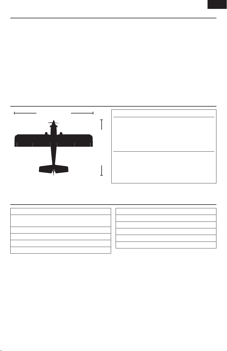
Table of Contents
Specifi cations ...................................................................3
Prefl ight Checklist .............................................................3
Transmitter and Receiver Binding ......................................4
®
SAFE
Select Technology ..................................................4
Transmitter Setup .............................................................5
Dual Rates and Expos .......................................................5
ESC/Receiver Arming, Battery Installation
and Center of Gravity ........................................................6
Control Direction Tests ......................................................7
Control Centering .............................................................8
Control Horn Settings ........................................................8
Low Voltage CutOff ...........................................................8
Flying Tips and Repairs .....................................................9
Post Flight Checklist .........................................................9
Specifi cations
EN
Power Components Service ............................................10
Slat Installation (Optional) ...............................................11
Float installation (Optional) ..............................................11
AS3X Troubleshooting Guide ...........................................12
Troubleshooting Guide ....................................................12
Troubleshooting Guide (Continued) ..................................13
Limited Warranty ............................................................13
Warranty and Service Contact Information ......................15
FCC Information ..............................................................15
IC Information .................................................................15
Compliance Information for the European Union ..............16
Replacement Parts ..........................................................58
Optional Parts and Accessories .......................................59
27.6 in (700mm)
Wing Area: 119.0 sq In (7.7 sq Dm)
Weight: 4.37oz (124g)
Prefl ight Checklist
1. Charge fl ight battery.
2. Install fl ight battery in aircraft (once it has been fully
charged).
3. Bind aircraft to transmitter.
4. Make sure linkages move freely.
5. Perform Control Direction Test with transmitter.
6. Perform AS3X control Direction Test with aircraft.
Installed
Motor: BL180 Brushless Outrunner 3,400Kv (EFLUM6960)
Receiver : DSM2® 6 Ch. UM AS3X® RX BL-ESC (EFLU4864)
Servos : (2) 2.3-Gram Performance Linear Long Throw
Offset Servo (SPMSA2030LO)
Required to Complete
Battery: 280mAh 2S 7.4V 30C Li-Po, (EFLB2802S30)
18.4 in (467mm)
Battery Charger: Celectra™ 2S 7.4V DC Li-Po Charger
Recommended Transmitter: Full range Spektrum™
DSM2®/DSMX® with dual-rates (DXe and up)
7. Set dual rates.
8. Adjust center of gravity.
9. Perform a radio system Range Check.
10. Find a safe and open area.
11. Plan fl ight for fl ying fi eld conditions.
12. Set fi ght timer for 5 minutes for fi rst fl ight.
(EFLUC1007)
3
Page 4

EN
Transmitter and Receiver Binding
Binding is the process of programming the receiver to recognize the GUID (Globally Unique Identifi er) code of a single
specifi c transmitter. You need to ‘bind’ your chosen Spektrum™ DSM2/DSMX technology equipped aircraft transmitter to
the receiver for proper operation. Any full range Spektrum DSM2/DSMX transmitter can bind to the DSM2/DSMX receiver.
Binding Procedure
CAUTION: When using a Futaba transmitter with a Spektrum DSM® module, you must reverse the throttle
channel and rebind. Refer to your Spektrum module manual for binding and failsafe instructions. Refer to your
Futaba transmitter manual for instructions on reversing the throttle channel.
1. Refer to your transmitter’s unique instructions for binding to a receiver (location of transmitter’s Bind control).
2. Make sure the fl ight battery is disconnected from the aircraft.
3. Power off your transmitter.
4. Set the aircraft upright on its wheels and connect the fl ight battery in the aircraft. The receiver LED will begin
to fl ash rapidly (typically after 5 seconds)
5. Make sure the transmitter controls are neutral and the throttle and throttle trim are in low position.
6. Put your transmitter into bind mode. Refer to your transmitter’s manual for binding button or switch instructions.
7. After 5 to 10 seconds, the receiver status LED will turn solid, indicating that the receiver is bound to the
transmitter. If the LED does not turn solid, refer to the Troubleshooting Guide at the back of the manual.
For subsequent fl ights, power ON the transmitter for 5 seconds before connecting the fl ight battery.
SAFE® Select Technology
The evolutionary SAFE® Select technology can offer an extra level of protection so you can perform the fi rst fl ight
with confi dence. No complex transmitter programming is required. Just simply fl ip your GEAR switch to position 1
(Channel 5) to make the SAFE Select system active. Flip the Gear switch back to turn OFF SAFE Select and fl y with just
the assistance of AS3X® technology.
When activated, bank and pitch limitations keep you from over-controlling and automatic self-leveling makes recovery
from risky or confusing attitudes as simple as releasing the sticks. In fact, with the aileron, elevator and rudder sticks in
the neutral position, SAFE Select will automatically keep the airplane in a straight and level attitude.
4
Page 5
Transmitter Setup
To obtain the best fl ight performance, we recommend using a DSM2®/DSMX
transmitter capable of Dual Rates. Before binding, ensure that you are starting
with a blank acro model in your transmitter.
IMPORTANT: After you set up your model, always rebind the transmitter
and receiver to set the desired failsafe positions.
Program Your Transmitter
1. Start with a new ACRO Model.
2. Set Aircraft Type : Wing >1Ail 1Flap
3. Leave all settings at their default values.
The Gear Switch (ch 5) will control the Safe mode function.
• Switch position 0 = SAFE Mode
• Switch position 1 = AS3X Mode
: Tail > Normal
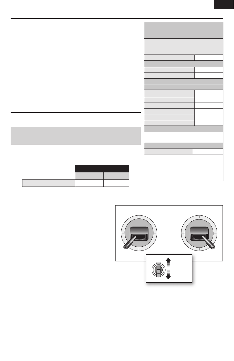
Dual Rates and Expos
The suggested settings shown here are the recommended starting settings.
Adjust according to the individual preferences after the initial fl ight.
NOTICE: Do not set your transmitter travel adjust over 100%. If
the TRAVEL ADJUST is set over 100%, it will not result in more control
movement, it will overdrive the servo and cause damage.
It is normal for linear servos to make signifi cant noise. The noise is not an
indication of a faulty servo.
TIP: For the fi rst fl ight, fl y the model in low rate.
Dual Rates
Low
Aileron, Elevator, Rudder 70% 100%
High
®
Computerized Transmitter Setup
(DX6e, DX6 G2, DX7 G2, DX8 G2, DX9,
Start all transmitter programming with a blank
ACRO model (do a model reset), then name
Set Servo Travel to: 100%
F-Mode Setup
Switch 1 Inhibit
Switch 2 Inhibit
Channel Assign
Channel Input Confi g
1 Throttle
2 Aileron
3 Elevator
4 Rudder
5 Gear SAFE/AS3X
6 Aux 1 FLAP
Frame Rate
Function List
Timer 6:00
Set FLAP SYSTEM:
SELECT SWITCH
POS 0: -90% FLAP
POS 1: 0% FLAP
POS 2: 90% FLAP
DX18 and DX20)
the model.
22mz
DSMX
EN
To enable and disable SAFE® Select Technology use the following steps.
1. Power on the transmitter.
2. Power on the aircraft.
3. Hold both transmitter sticks to the outside bottom
corners and toggle the Gear switch 5 times
(1 toggle = full up and down). The control surfaces
of the aircraft will move, indicating SAFE Select has
been enabled or disabled.
Repeat the process again to re-enable or disable
SAFE Select.
Mode 1 and 2 Transmitters
100%
x 5
100%
5
Page 6
EN
1-2-3-4-5 Sec.
1
3
4
2
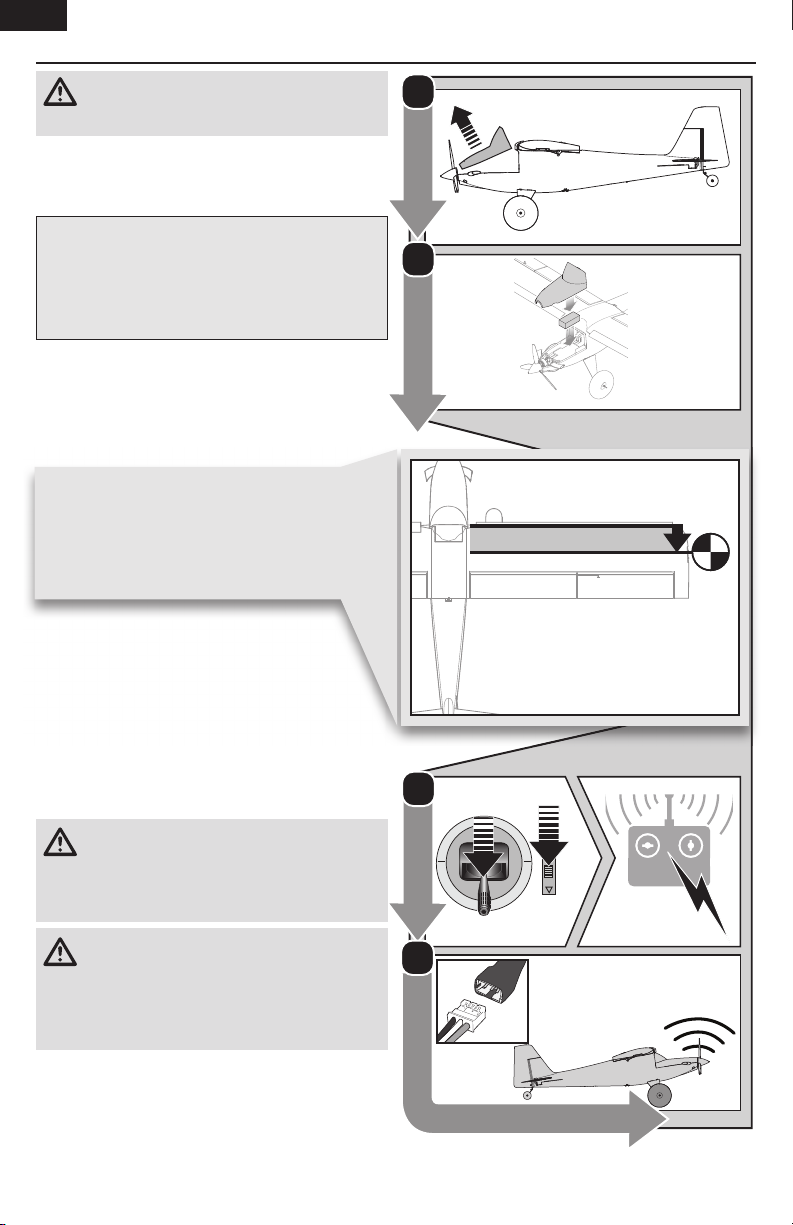
ESC/Receiver Arming, Battery Installation and Center of Gravity
CAUTION: Always keep hands away from the
propeller. When armed, the motor will turn the
propeller in response to any throttle movement.
Arming the ESC/receiver also occurs after binding as
previously described, but subsequent connection of a
fl ight battery requires the following steps.
AS3X
The AS3X® system will not activate until the throttle
stick or trim is increased for the fi rst time. Once active,
the control surfaces may move rapidly and noisily on
the aircraft. This is normal. AS3X technology will remain
active until the battery is disconnected.
1. Remove the battery hatch from the fuselage.
2. Install the flight battery in the center of the battery
tray. Ensure the battery is secured by the hook and
loop strip.
Center of Gravity (CG)
Measure back 28mm from the leading edge of
the top wing, where the wing meets the fuselage
and place a mark. Balance the airplane on this CG
mark. The easiest way to achieve CG is to balance
the aircraft upright.
28mm
3. Lower the throttle and throttle trim to the lowest
settings on your transmitter. Power on your
transmitter, then wait 5 seconds.
4. Connect the battery to the ESC, noting proper polarity.
Keep the aircraft upright (on its gear)and immobile
and away from wind for 5 seconds to allow the AS3X
system to initialize. A series of tones and a continuous
LED indicates a successful connection.
CAUTION: Always disconnect the Li-Po battery
from the ESC when not fl ying to eliminate power
supplied to the motor. The ESC does not have an arming
switch and will respond to any transmitter input when a
signal is present.
CAUTION: Always disconnect the Li-Po battery
from the ESC when not fl ying to avoid overdischarging the battery. Batteries discharged to a voltage
lower than the lowest approved voltage may become
damaged, resulting in loss of performance and potential
fi re when batteries are charged.
6
Page 7

Control Direction Tests
Traditional Control Direction Test
You should bind your aircraft and transmitter before doing these tests. Move the controls on the transmitter to make sure
the aircraft control surfaces move correctly and in the proper direction. Make sure the tail linkages move freely and that
paint or decals are not adhered to them.
AS3X® Control Direction Test
This test ensures that the AS3X® control system is functioning properly.
Aircraft movement AS3X Reaction
1. Advance the throttle above 25%
to activate the AS3X system.
2. Fully lower the throttle.
3. Move the entire aircraft as
shown and ensure the control
surfaces move in the direction
indicated in the graphic. If the
control surfaces do not respond
as shown, do not fly the aircraft.
Refer to the receiver manual for
more information.
Once the AS3X system is active,
control surfaces may move rapidly.
This is normal. AS3X is active until
the battery is disconnected.
ElevatorAileronRudder
EN
7
Page 8

EN
Control Centering
Before your fi rst fl ight, make sure the aircraft’s control
surfaces are centered.
1. Power on the transmitter and then the aircraft.
2. Set all transmitter trims and sub-trims to zero.
3. Check the control surfaces to make sure they are
centered.
4. If centering is required, use a pair of pliers to carefully
bend the metal linkage (see illustration).
In fl ight trimming may be required.
During your fi rst fl ight, the aircraft should fl y straight and
level. Use your transmitter trims to fi ne-tune the aircraft’s
fl ight path until it has been corrected. Any transmitter trim
that requires 4 or more clicks of trim (per channel), should
be mechanically centered. Note the control surface’s
postion and return the transmitter trim to zero. Adjust the
linkages mechanically so that the control surfaces are in
the fl ight trimmed position.
Control Horn Settings
The illustration shows linkage positions chosen for the best
aerobatic response. Linkage connections on the control
horns directly affect aircraft response.
Make the U-shape narrower to make the connector shorter.
Make the U-shape wider to make the linkage longer.
Aileron
RudderElevator
Low Voltage CutOff
LVC is a feature built into your ESC to protect the battery
from over-discharge. When the battery charge becomes too
low, LVC limits power supplied to the motor. When you hear
the motor power pulse, land the aircraft immediately and
recharge the fl ight battery.
NOTICE: Do not rely on LVC to determine when to land
your aircraft. Set a fl ight timer to the recommended fl ight
time. Repeated fl ying to LVC will damage the battery.
8
Page 9

Flying Tips and Repairs
EN
We recommend fl ying your aircraft outside in calm
conditions. Always avoid fl ying near houses, trees, wires
and buildings. You should also be careful to avoid fl ying
in areas where there are many people, such as busy
parks, schoolyards or soccer fi elds. Consult local laws and
ordinances before choosing a location to fl y your aircraft.
Takeoff
Place the aircraft in position for takeoff (facing into the
wind if fl ying outdoors). Set dual rates to low position and
gradually increase the throttle to ¾ to full and steer with
the rudder. Pull back gently on the elevator and climb to
check trim. Once the trim is adjusted, begin exploring the
fl ight envelope of the aircraft.
Landing
Land into the wind. This is very important for this model.
Fly the aircraft to approximately 6 inches (15cm) or less
above the runway, using a small amount of throttle for
the entire descent. Keep the throttle on until the aircraft is
ready to fl are.
During fl are, keep the wings
level and the airplane pointed
into the wind. Gently lower the
throttle while pulling back on
the elevator to bring the aircraft
down on all three wheels.
Failure to lower the throttle
stick and trim to the lowest
possible positions during a
crash could result in damage
to the ESC in the receiver
unit, which may require
replacement.
CAUTION: Always
decrease throttle
at propeller strike.
Over Current Protection (OCP)
This aircraft is equipped with Over Current Protection
(OCP). This feature protects the ESC from overheating. OCP
stops the motor when the transmitter throttle is set too high
and the propeller cannot turn. The OCP will only activate
when the throttle stick is positioned just above 1/2 throttle.
After the ESC stops the motor, fully lower the throttle to
re-arm the ESC.
NOTICE: Crash damage is not covered under the warranty.
Repairs
Repair the aircraft using foam-compatible CA
(cyanoacrylate adhesive) or clear tape. Only use foam-
compatible CA, as other types of glue can damage the
foam. When parts are not repairable, see the Replacement
Parts List for ordering by item number.
For a listing of all replacement and optional parts, refer to
the list at the end of this manual.
NOTICE: Use of foam-compatible CA accelerant on your
aircraft can damage paint. DO NOT handle the aircraft
until the accelerant fully dries.
NOTICE: When you are fi nished fl ying, never leave the
aircraft in direct sunlight or in a hot, enclosed area such
as a car. Doing so can damage the foam.
Post Flight Checklist
1. Disconnect the flight battery from the ESC
(Required for safety and battery life).
2. Power OFF the transmitter.
3. Remove the flight battery from the aircraft.
4. Recharge the flight battery.
5. Store the flight battery apart from the aircraft and
monitor the battery charge.
6. Make note of the flight conditions and flight plan
results, planning for future flights.
9
Page 10

EN
Power Components Service
Disassembly
CAUTION: DO NOT handle the propeller
while the fl ight battery is connected to
the ESC. Personal injury could result.
Propeller
1. Carefully remove the screw (A) and propeller (B)
from the motor shaft.
Motor
1. Remove the battery hatch by gripping the front of the
hatch, then pulling it up and away from the fuselage.
2. Disconnect the motor wire connector from
the ESC/receiver connector.
3. Remove the screw (C) and motor (D) from the motor
mount.
4. Remove 3 screws (E) and the prop adapter (F)from
the motor. The motor magnet may attract screws to
the motor.
B
A
C
D
Assembly
Assemble in reverse order.
• Connect the motor wire connector to the ESC/receiver.
• The propeller size numbers (5.75x2.5) must face out
from the motor for correct propeller operation.
• Ensure the propeller adapter and motor mount are fully
connected to the motor.
10
E
F
Page 11

Slat Installation (Optional)
Required Adhesives
Foam Safe CA
1. Apply a small drop of foam safe CA to each mount.
2. Carefully mount the slat onto the wing with the
rounded edge facing forward.
Float installation (Optional)
Landing Gear Removal
1. Carefully place the aircraft on its back.
2. Remove the 4 screws and 2 plates securing the
landing gear.
3. Remove the other 4 screws and 2 plates for the
rear float mount. Save all screws and plates for the
float installlation.
4. Remove the landing gear.
EN
Float Installation
1. Install the included rear float wire onto the floats.
2. Install the floats as shown.
3. Install the 6 screws and 4 plates removed above.
11
Page 12

EN
AS3X Troubleshooting Guide
Problem Possible Cause Solution
Control surfaces not at
neutral position when
transmitter controls are
at neutral
Model fl ies inconsistently
from fl ight to fl ight
Controls oscillate in
fl ight, (model rapidly
jumps or moves)
Control surfaces may not have been
mechanically centered from factory
Aircraft was not kept immobile for 5 seconds
after battery was plugged in
Aircraft was not kept immobile for 5 seconds
after battery was plugged in
Trims are moved too far from neutral position
Propeller, spinner or motor is unbalanced,
causing excessive vibration
Nut on prop shaft is too loose, causing
excessive vibration
Troubleshooting Guide
Problem Possible Cause Solution
Aircraft will not respond
to throttle but responds
to other controls
Extra propeller noise or
extra vibration
Reduced fl ight time or
aircraft underpowered
LED on receiver fl ashes
and aircraft will not bind
to transmitter (during
binding)
Throttle stick and/or throttle trim too high
Throttle channel is reversed Reverse throttle channel on transmitter
Motor disconnected from receiver
Propeller, spinner or motor is unbalanced,
causing excessive vibration
Prop screw is too loose Tighten the prop screw
Flight battery charge is low Completely recharge fl ight battery
Propeller installed backwards Install propeller with numbers facing forward
Flight battery damaged or old.
Flight conditions may be too cold Make sure battery is warm before use
Battery capacity too low for fl ight conditions
Transmitter too near aircraft during binding
process
Bind switch or button not held long enough
during bind process
Aircraft or transmitter is too close to large
metal object, wireless source or another
transmitter
Center control surfaces mechanically by
adjusting the U-bends on control linkages
Keep the aircraft immobile for 5 seconds after
plugging in the battery
Keep the aircraft immobile for 5 seconds after
plugging in the battery
Neutralize trims and mechanically adjust
linkages to center control surfaces
Balance parts or replace it if damaged
Tighten the prop shaft nut 1/2 turn
Reset controls with throttle stick and throttle
trim at lowest setting
Open fuselage and make sure motor is
connected to the receiver
Balance parts or replace it if damaged
Replace fl ight battery and follow fl ight battery
instructions
Replace battery or use a larger capacity
battery
Power off transmitter, move transmitter a
larger distance from aircraft, disconnect and
reconnect fl ight battery to aircraft and follow
binding instructions
Power off transmitter and repeat bind
process. Hold transmitter bind button or
switch until receiver is bound
Move aircraft and transmitter to another
location and attempt binding again
12
Page 13

Troubleshooting Guide (Continued)
Problem Possible Cause Solution
Less than a 5-second wait between fi rst
powering on transmitter and connecting
fl ight battery to aircraft
LED on receiver fl ashes
rapidly and aircraft
will not respond to
transmitter (after
binding)
Control surface does
not move
Controls reversed Transmitter settings reversed Adjust controls on transmitter appropriately
Motor loses power Damage to motor or power components
Motor power quickly
decreases and
increases then motor
loses power
Motor/ESC is not armed
after landing
Servo locks or freezes
at full travel
Aircraft bound to different model memory
(ModelMatch™ radios only)
Flight battery/transmitter battery charge is
too low
Transmitter may not be compatible with
Spektrum DSM2/DSMX technology
Aircraft or transmitter is too close to large
metal object, wireless source or another
transmitter
Control surface, control horn, linkage or
servo damage
Wires damaged or connections loose
Flight battery charge is low Fully recharge fl ight battery
Control linkage does not move freely Make sure control linkage moves freely
Battery power is down to the point of
receiver/ESC Low Voltage Cutoff (LVC)
Over Current Protection (OCP) stops the
motor when the transmitter throttle is set
high and the propeller cannot turn
Travel adjust value is set above 100%,
overdriving the servo
Leaving transmitter on, disconnect and
reconnect fl ight battery to aircraft
Select correct model memory on transmitter
and disconnect and reconnect fl ight battery
to aircraft
Replace/recharge batteries
Use a genuine Spektrum DSM2/DSMX
transmitter
Move aircraft and transmitter to
anotherlocation and attempt linking again
Replace or repair damaged parts and adjust
controls
Do a check of wires and connections,
connect or replace as needed
Do a check of motor and power components
for damage (replace as needed)
Recharge fl ight battery or replace battery that
is no longer performing
Fully lower throttle and throttle trim to arm
ESC
Set Travel adjust to 100% or less and/or
set sub-trims to Zero and adjust linkages
mechanically
EN
Limited Warranty
What this Warranty Covers
Horizon Hobby, LLC, (Horizon) warrants to the original
purchaser that the product purchased (the “Product”) will
be free from defects in materials and workmanship at the
date of purchase.
What is Not Covered
This warranty is not transferable and does not cover
(i) cosmetic damage, (ii) damage due to acts of God,
accident, misuse, abuse, negligence, commercial
use, or due to improper use, installation, operation or
maintenance, (iii) modifi cation of or to any part of the
Product, (iv) attempted service by anyone other than
a Horizon Hobby authorized service center, (v) Product
not purchased from an authorized Horizon dealer, or
(vi) Product not compliant with applicable technical
regulations, or (vii) use that violates any applicable laws,
rules, or regulations.
OTHER THAN THE EXPRESS WARRANTY ABOVE, HORIZON
MAKES NO OTHER WARRANTY OR REPRESENTATION, AND
HEREBY DISCLAIMS ANY AND ALL IMPLIED WARRANTIES,
INCLUDING, WITHOUT LIMITATION, THE IMPLIED
WARRANTIES OF NON-INFRINGEMENT, MERCHANTABILITY
AND FITNESS FOR A PARTICULAR PURPOSE. THE
PURCHASER ACKNOWLEDGES THAT THEY ALONE HAVE
DETERMINED THAT THE PRODUCT WILL SUITABLY MEET
THE REQUIREMENTS OF THE PURCHASER’S INTENDED
USE.
Purchaser’s Remedy
Horizon’s sole obligation and purchaser’s sole and
exclusive remedy shall be that Horizon will, at its option,
either (i) service, or (ii) replace, any Product determined by
Horizon to be defective.
Horizon reserves the right to inspect any and all Product(s)
involved in a warranty claim. Service or replacement
decisions are at the sole discretion of Horizon. Proof of
13
Page 14

EN
purchase is required for all warranty claims. SERVICE OR
REPLACEMENT AS PROVIDED UNDER THIS WARRANTY IS
THE PURCHASER’S SOLE AND EXCLUSIVE REMEDY.
Limitation of Liability
HORIZON SHALL NOT BE LIABLE FOR SPECIAL, INDIRECT,
INCIDENTAL OR CONSEQUENTIAL DAMAGES, LOSS OF
PROFITS OR PRODUCTION OR COMMERCIAL LOSS IN ANY
WAY, REGARDLESS OF WHETHER SUCH CLAIM IS BASED
IN CONTRACT, WARRANTY, TORT, NEGLIGENCE, STRICT
LIABILITY OR ANY OTHER THEORY OF LIABILITY, EVEN IF
HORIZON HAS BEEN ADVISED OF THE POSSIBILITY OF
SUCH DAMAGES. Further, in no event shall the liability
of Horizon exceed the individual price of the Product on
which liability is asserted. As Horizon has no control over
use, setup, fi nal assembly, modifi cation or misuse, no
liability shall be assumed nor accepted for any resulting
damage or injury. By the act of use, setup or assembly, the
user accepts all resulting liability. If you as the purchaser
or user are not prepared to accept the liability associated
with the use of the Product, purchaser is advised to return
the Product immediately in new and unused condition to
the place of purchase.
Law
These terms are governed by Illinois law (without regard to
confl ict of law principals). This warranty gives you specifi c
legal rights, and you may also have other rights which vary
from state to state. Horizon reserves the right to change
or modify this warranty at any time without notice.
WARRANTY SERVICES
Questions, Assistance, and Services
Your local hobby store and/or place of purchase cannot
provide warranty support or service. Once assembly, setup
or use of the Product has been started, you must contact
your local distributor or Horizon directly. This will enable
Horizon to better answer your questions and service
you in the event that you may need any assistance. For
questions or assistance, please visit our website at www.
horizonhobby.com, submit a Product Support Inquiry,
or call the toll free telephone number referenced in the
Warranty and Service Contact Information section to speak
with a Product Support representative.
Inspection or Services
If this Product needs to be inspected or serviced and is
compliant in the country you live and use the Product in,
please use the Horizon Online Service Request submission
process found on our website or call Horizon to obtain a
Return Merchandise Authorization (RMA) number. Pack
the Product securely using a shipping carton. Please note
that original boxes may be included, but are not designed
to withstand the rigors of shipping without additional
protection. Ship via a carrier that provides tracking and
insurance for lost or damaged parcels, as Horizon is not
responsible for merchandise until it arrives and is accepted
at our facility. An Online Service Request is available at
http://www.horizonhobby.com/content/service-center_
render-service-center. If you do not have internet access,
please contact Horizon Product Support to obtain a RMA
number along with instructions for submitting your product
for service. When calling Horizon, you will be asked to
provide your complete name, street address, email address
and phone number where you can be reached during
business hours. When sending product into Horizon, please
include your RMA number, a list of the included items, and
a brief summary of the problem. A copy of your original
sales receipt must be included for warranty consideration.
Be sure your name, address, and RMA number are clearly
written on the outside of the shipping carton.
NOTICE: Do not ship LiPo batteries to Horizon. If you
have any issue with a LiPo battery, please contact
the appropriate Horizon Product Support offi ce.
Warranty Requirements
For Warranty consideration, you must include your
original sales receipt verifying the proof-of-purchase
date. Provided warranty conditions have been met, your
Product will be serviced or replaced free of charge.
Service or replacement decisions are at the sole discretion
of Horizon.
Non-Warranty Service
Should your service not be covered by warranty,
service will be completed and payment will be
required without notifi cation or estimate of the
expense unless the expense exceeds 50% of the retail
purchase cost. By submitting the item for service you are
agreeing to payment of the service without notifi cation.
Service estimates are available upon request. You must
include this request with your item submitted for service.
Non-warranty service estimates will be billed a minimum
of ½ hour of labor. In addition you will be billed for return
freight. Horizon accepts money orders and cashier’s
checks, as well as Visa, MasterCard, American Express,
and Discover cards. By submitting any item to Horizon
for service, you are agreeing to Horizon’s Terms and
Conditions found on our website http://www.horizonhobby.
com/content/service-center_render-service-center.
ATTENTION: Horizon service is limited to Product
compliant in the country of use and ownership.
If received, a non-compliant Product will not be
serviced. Further, the sender will be responsible
for arranging return shipment of the un-serviced
Product, through a carrier of the sender’s choice
and at the sender’s expense. Horizon will hold
non-compliant Product for a period of 60 days from
notifi cation, after which it will be discarded.
10/15
14
Page 15

Warranty and Service Contact Information
Country of Purchase Horizon Hobby Contact Information Address
United States of
America
EU
Horizon Service Center
(Repairs and Repair Requests)
Horizon Product Support
(Product Technical Assistance)
Sales
Horizon Technischer Service service@horizonhobby.eu Hanskampring 9
Sales: Horizon Hobby GmbH +49 (0) 4121 2655 100
servicecenter.horizonhobby.com/
RequestForm/
productsupport@horizonhobby.com
877-504-0233
websales@horizonhobby.com
800-338-4639
2904 Research Rd
Champaign, Illinois, 61822
USA
D 22885 Barsbüttel,
Germany
FCC Information
FCC ID: BRWEFLU4864
This device complies with part 15 of the FCC rules.
Operation is subject to the following two conditions: (1) This
device may not cause harmful interference, and (2) this
device must accept any interference received, including
interference that may cause undesired operation.
CAUTION: Changes or modifi cations not expressly
approved by the party responsible for compliance could
void the user’s authority to operate the equipment.
This product contains a radio transmitter with wireless
technology which has been tested and found to be
compliant with the applicable regulations governing a radio
transmitter in the 2.400GHz to 2.4835GHz frequency range.
Supplier’s Declaration of Conformity
Turbo Timber BNF Basic with AS3X and SAFE Select
(EFLU6950)
This device complies with part 15 of the FCC Rules.
Operation is subject to the following two conditions: (1) This
device may not cause harmful interference, and (2) this
device must accept any interference received, including
interference that may cause undesired operation.
CAUTION: Changes or modifi cations not expressly
approved by the party responsible for compliance could
void the user’s authority to operate the equipment.
NOTE: This equipment has been tested and found to comply
with the limits for a Class B digital device, pursuant to part
15 of the FCC Rules. These limits are designed to provide
reasonable protection against harmful interference in a
residential installation. This equipment generates, uses
and can radiate radio frequency energy and, if not installed
and used in accordance with the instructions, may cause
harmful interference to radio communications. However,
there is no guarantee that interference will not occur in a
particular installation. If this equipment does cause harmful
interference to radio or television reception, which can be
determined by turning the equipment off and on, the user is
encouraged to try to correct the interference by one or more
of the following measures:
• Reorient or relocate the receiving antenna.
• Increase the separation between the equipment and
receiver.
• Connect the equipment into an outlet on a circuit
different from that to which the receiver is connected.
• Consult the dealer or an experienced radio/TV technician
for help.
Horizon Hobby, LLC
2904 Research Rd.,
Champaign, IL 61822
Email: compliance@horizonhobby.com
Web: HorizonHobby.com
EN
IC Information
CAN ICES-3 (B)/NMB-3(B)
IC: 6157A-EFLU4864
This device complies with Industry Canada licence-exempt RSS standard(s). Operation is subject to the following two
conditions: (1) this device may not cause interference, and (2) this device must accept any interference, including
interference that may cause undesired operation of the device.
Compliance Information for the European Union
EU Compliance Statement:
Horizon Hobby, LLC hereby declares that this product is in compliance with the essential requirements and
other relevant provisions of the RED and EMC Directive.
A copy of the EU Declaration of Conformity is available online at: http://www.horizonhobby.com/content/support-render-compliance.
Instructions for disposal of WEEE by users in the European Union
This product must not be disposed of with other waste. Instead, it is the user’s responsibility to
dispose of their waste equipment by handing it over to a designated collections point for the
recycling of waste electrical and electronic equipment. The separate collection and recycling of
your waste equipment at the time of disposal will help to conserve natural resources and
ensure that it is recycled in a manner that protects human health and the environment. For
more information about where you can drop off your waste equipment for recycling, please
contact your local city offi ce, your household waste disposal service or where you purchased
the product.
15
Page 16

Replacement Parts / Ersatzteile / Pièces de rechange / Recapiti per i ricambi
Part # • Nummer
Numéro • Codice
EFLU6953 Fuselage Rumpf Fuselage Fusoliera
EFLU6954 Wing Set Tragfl ächensatz Ensemble d’ailes Set ali
EFLU6955 Tail set with horns Hecksatz mit Fühlern
EFLU6956 Landing gear set Fahrwerksatz
EFLU6957 Battery hatch Akku-Abdeckung Trappe de la batterie Sportello batteria
EFLU3956 Led set LED-Satz Ensemble de DEL Set LED
EFLU6958 Decal set Decal-Satz Lot d'autocollants Set decalcomanie
EFLU6959 Spinner Spinner Cône Ogiva
EFLU3960 Leading edge slats Vorfl ügel Becs de bord d’attaque Slat bordo d’attacco
EFLU3961 Pushrods set Schubstangensatz
EFLUM6960
EFLUP120703B
SPMSA2030LO
SPMA2000
SPMSA2030L
EFLA6420BL
Description Beschreibung Description Descrizione
BL180 Brushless
Outrunner 3,400Kv
120mm x 70mm 3
blade propeller
2.3g linear long
throw offset servo
3" Ultra Micro
Extension
2.3g Performance
linear long throw
servo (for fl aps)
RX DSMX 6-ch AS3X
SAFE Brushless ESC
BL180 bürstenloser
Außenmotor 3.400kV
3-Blatt-Propeller 120
mm x 70 mm
2,3g linearer OffsetServo mit langem
Stellweg
7,62cm Ultra MicroVerlängerung
2,3linearer LeistungsServo mit langem
Stellweg (für
Landeklappen)
RX DSMX 6-Kanal AS3X
bürstenloser SAFEGeschwindigkeitsregler
Ensemble d’empennage
avec renvois de
commande
Ensemble de train
d’atterrissage
Ensemble de barres de
liaison
Cage tournante sans
balais BL180, 3400Kv
Elica 3 pale 120 x 70 mmHélice à 3 pales 120
Servo linéaire longue
portée décalé 2,3g
Rallonge Ultra Micro de
7,62 cm
Servo longue portée
linéaire Performance
2,3 grammes (pour les
volets)
Variateur ESC sans
balais AS3X SAFE RX
DSMX 6 canaux
Set coda con
squadrette
Set carrello
d’atterraggio
Set aste di comando
BL180 Brushless
Outrunner 3.400 Kv
mm x 70 mm
Servocomandi offset
a corsa lunga da
2,3 g
Estensione Ultra
Micro da 7,62 cm
Servocomandi lineari
performance a corsa
lunga da 2,3 g (per
i fl ap)
RX DSMX 6
canali AS3X SAFE
Brushless ESC
Page 17

Optional Parts and Accessories / Optionale Bauteile und Zubehörteile /
Pièces optionnelles et accessoires / Parti opzionali e accessori
Part # • Nummer
Numéro • Codice
PKZ1039
SPMA3060
EFLUC1007
EFLC1105A
EFLUC1008
EFLB2002S30
EFLB2802S30
EFLA700UM
EFLA7001UM
EFLC4000/UK/AU/EU
EFLA111
Description Beschreibung Description Descrizione
Hook and Loop Set (5):
Ultra Micros
USB-Interface: UM
AS3X Programmer
Celectra 2S 7.4V
DC Li-Po Charger
1S-2S AC/DC Li-Po
Balancing Charger
DC Power Cord for
EFLUC1007
200mAh 2s 7.4V DC
Li–Po, 26AWG
280mAh 2s 7.4V DC
Li–Po, 26AWG
Charger Plug Adapter:
EFL
Charger Plug Adapter:
Thunder Power
AC to 12V DC,1.5 Amp
Power Supply (Based
upon your sales
Region)
Li-Po Cell Voltage
Checker
DXe DSMX 6-Channel
Transmitter
DX6e DSMX 6-Channel
Transmitter
DX6 Gen 2 DSMX
6-Channel Transmitter
DX7 Gen 2 DSMX
7-Channel Transmitter
DX8 Gen 2 DSMX
7-Channel Transmitter
DX9 DSMX
9-Channel Transmitter
DX18/18QQ DSMX
Transmitter
DX20 DSMX
Transmitter
Klettband (5): Ultra
Micros
UM AS3X
Programmiergerät
Celectra 2S 7.4V DC
Li-Po Ladegerät
E-fl ite Ultra Micro-4,
4x9W, AC/DC
Akkuladegerät, EU
Anschlußstecker mit
Krokodilklemmen für
EFLUC1007
200mAh 2S 7.4V
30C Li-Po Akku
280mAh 2S 7.4V
30C Li-Po Akku
Ladekabel Adapter EFL
Ladekabel Adapter
Thunder Power
Netzteil 12V 1,5
A (Basierend nach
Vertriebsregion)
E-fl ite Li-Po Cell Volt
Checker
DXe DSMX 6-Kanal
Sender
DX6e DSMX 6-Kanal
Sender
DX6 Gen 2 DSMX
6-Kanal Sender
Spektrum DX7 Gen 2
7 Kanal Sender
Spektrum DX7 Gen 2
8 Kanal Sender
Spektrum DX9
9 Kanal Sender
Spektrum DX18/18QQ
nur Sender
Spektrum DX20 nur
Sender
Bande auto-agrippante
(5)
Interface USB pour
module AS6410NBL
Chargeur Celectra
Li-Po 2S 7,4V
Chargeur/équilibreur
Li-Po 1 ou 2S AC/DC
Câble d’alimentation
pour EFLUC1007
Batterie Li-Po 2S 7,4V
200mA 30C, 26AWG
Batterie Li-Po 2S 7,4V
280mA 30C, 26AWG
Adaptateur pour prise
chargeur - EFL
Adaptateur pour prise
chargeur - Thunder
Power
Alimentation CA vers
12V CC, 1,5 A (En
fonction de votre
région)
Contrôleur de tension
des éléments Li-Po
Emetteur DXe DSMX
6 voies
Emetteur DX6e DSMX
6 voies
Emetteur DX6 Gen 2
DSMX 6 voies
Emetteur DX7 Gen 2
DSMX 7 voies
Emetteur DX8 Gen 2
DSMX 8 voies
Emetteur DX9 DSMX
9 voies
Emetteur DX18/18QQ
DSMX
Emetteur DX20 DSMX
Set fascette fi ssaggio
(5): Ultra Micros
Celectra 2S 7.4V DC
Li-Po Caricabatterie
1S-2S AC/DC Li-Po
Caricatore con
bilanciamento
Cavo alimentazione
per EFLUC1007
200mAh 2S 7.4V 30C
Li-Po, 26AWG
280mAh 2S 7.4V 30C
Li-Po, 26AWG
Adattatore connettore
caricabatterie: EFL
Adattatore connettore
caricabatterie:
Thunder Power
Alimentatore CA - 12V
CC da 1,5 A (in base al
Paese di vendita)
Strumento per misura
tensione celle LiPo
DXe DSMX
Trasmettitore 6 canali
DX6e DSMX
Trasmettitore 6 canali
DX6 Gen 2 DSMX
Trasmettitore 6 canali
DX7 Gen 2 DSMX
Trasmettitore 7 canali
DX8 Gen 2 DSMX
Trasmettitore 8 canali
DX9 DSMX
Trasmettitore 9 canali
DX18/18QQ DSMX
Solo trasmettitore
DX20DSMX Solo
trasmettitore
Page 18

E-fl ite, Timber, AS3X, UMX, SAFE, the SAFE logo, DSM, DSM2, DSMX, ModelMatch, Bind-N-Fly, BNF, Celectra
and the Horizon Hobby logo are trademarks or registered trademarks of Horizon Hobby, LLC.
The Spektrum trademark is used with permission of Bachmann Industries, Inc.
Futaba is a registered trademark of Futaba Denshi Kogyo Kabushiki Kaisha Corporation of Japan.
All other trademarks, service marks and logos are property of their respective owners.
US 9,930,567. US 10,419,970. US 9,056,667. US 9,753,457. US 10,078,329. US 7,898,130. US D578,146.
Created 12/19 61135.1 EFLU6950
© 2020 Horizon Hobby, LLC.
US 8,672,726. Other patents pending.
www.e-fl iterc.com
 Loading...