

Page 1

ASSEMBLY MANUAL
Specifications
Wingspan:.............................................................. 76 in (1676mm)
Length: .................................................................... 55 in (1397mm)
Wing Area: ............................................................ 2 AIL:1210 sq in (5934.5 sq dm)
4 AIL:1230 sq in (6025.5 sq dm)
Weight (approximate):........................................ 9–11 lb (2.7–3.15 kg)
Recommended Engines:..................................... 2-cycle:1.08–.150 cu in
4-cycle:1.00–1.80 cu in
TM
WE GET PEOPLE FLYING
TM
®
Page 2

2
Table of Contents
Table of Contents . . . . . . . . . . . . . . . . . . . . . . . . . . . . . . . . . . . . . . . . . . . . . . . . . . . . . . . . . . . . . . 2
Additional Required Equipment . . . . . . . . . . . . . . . . . . . . . . . . . . . . . . . . . . . . . . . . . . . . . . . . . . . . 3
Contents of Kit . . . . . . . . . . . . . . . . . . . . . . . . . . . . . . . . . . . . . . . . . . . . . . . . . . . . . . . . . . . . . . . . 3
Additional Required Tools and Adhesives . . . . . . . . . . . . . . . . . . . . . . . . . . . . . . . . . . . . . . . . . . . . . 4
Other Items Needed (not included in the kit) . . . . . . . . . . . . . . . . . . . . . . . . . . . . . . . . . . . . . . . . . . 4
Warning . . . . . . . . . . . . . . . . . . . . . . . . . . . . . . . . . . . . . . . . . . . . . . . . . . . . . . . . . . . . . . . . . . . . . 4
Warranty Information . . . . . . . . . . . . . . . . . . . . . . . . . . . . . . . . . . . . . . . . . . . . . . . . . . . . . . . . . . . . 5
Using the Manual . . . . . . . . . . . . . . . . . . . . . . . . . . . . . . . . . . . . . . . . . . . . . . . . . . . . . . . . . . . . . . 5
Before Starting Assembly . . . . . . . . . . . . . . . . . . . . . . . . . . . . . . . . . . . . . . . . . . . . . . . . . . . . . . . . 5
Section 1: Conventional Wing Assembly . . . . . . . . . . . . . . . . . . . . . . . . . . . . . . . . . . . . . . . . . . . . . 6
Section 1a: Quad-Flap Wing Assembly . . . . . . . . . . . . . . . . . . . . . . . . . . . . . . . . . . . . . . . . . . . . . . 8
Section 2: Joining the Wing Halves . . . . . . . . . . . . . . . . . . . . . . . . . . . . . . . . . . . . . . . . . . . . . . . . 10
Section 3: Aileron/Flap Servo Installation . . . . . . . . . . . . . . . . . . . . . . . . . . . . . . . . . . . . . . . . . . . 13
Section 4: Bolting the Wing to the Fuselage . . . . . . . . . . . . . . . . . . . . . . . . . . . . . . . . . . . . . . . . . . 16
Section 5: Horizontal Stabilizer Installation . . . . . . . . . . . . . . . . . . . . . . . . . . . . . . . . . . . . . . . . . . 19
Section 6: Vertical Stabilizer (Fin) Installation . . . . . . . . . . . . . . . . . . . . . . . . . . . . . . . . . . . . . . . . 22
Section 7: Rudder and Tail Wheel Assembly Installation . . . . . . . . . . . . . . . . . . . . . . . . . . . . . . . . . 24
Section 8: Hinging the Horizontal Stabilizer and Elevator . . . . . . . . . . . . . . . . . . . . . . . . . . . . . . . . 27
Section 9: Rudder and Elevator Control Horn Installation . . . . . . . . . . . . . . . . . . . . . . . . . . . . . . . . 28
Section 10: Main Landing Gear Installation . . . . . . . . . . . . . . . . . . . . . . . . . . . . . . . . . . . . . . . . . . 30
Section 11: Fuel Tank Assembly . . . . . . . . . . . . . . . . . . . . . . . . . . . . . . . . . . . . . . . . . . . . . . . . . . 31
Section 12: Mounting the Engine . . . . . . . . . . . . . . . . . . . . . . . . . . . . . . . . . . . . . . . . . . . . . . . . . . 33
Section 13: Radio System Installation . . . . . . . . . . . . . . . . . . . . . . . . . . . . . . . . . . . . . . . . . . . . . . 35
Section 14: Aileron and/or Quad-Flap Linkage Installation . . . . . . . . . . . . . . . . . . . . . . . . . . . . . . . 37
Section 15: Rudder, Elevator, and Throttle Pushrod Installation . . . . . . . . . . . . . . . . . . . . . . . . . . . . 40
Section 17: Balancing the Ultra Stick Lite . . . . . . . . . . . . . . . . . . . . . . . . . . . . . . . . . . . . . . . . . . . . 43
Section 16: Control Throw Recommendations . . . . . . . . . . . . . . . . . . . . . . . . . . . . . . . . . . . . . . . . 43
Section 18: Quad Flaps . . . . . . . . . . . . . . . . . . . . . . . . . . . . . . . . . . . . . . . . . . . . . . . . . . . . . . . . . 44
Section 19: Radio Programming Guide . . . . . . . . . . . . . . . . . . . . . . . . . . . . . . . . . . . . . . . . . . . . . 47
Programming Guide — JR XP652/642 . . . . . . . . . . . . . . . . . . . . . . . . . . . . . . . . . . . . . . . . . . . . . 47
Programming Guide — JR XP783/XP347/XP388S . . . . . . . . . . . . . . . . . . . . . . . . . . . . . . . . . . . . 53
Programming Guide — JR XP8103 . . . . . . . . . . . . . . . . . . . . . . . . . . . . . . . . . . . . . . . . . . . . . . . . 61
Programming Guide — JR 10X/10SXII/10SX . . . . . . . . . . . . . . . . . . . . . . . . . . . . . . . . . . . . . . . . 69
Programming Guide — Futaba 8UA/S . . . . . . . . . . . . . . . . . . . . . . . . . . . . . . . . . . . . . . . . . . . . . . 73
Range Testing the Radio . . . . . . . . . . . . . . . . . . . . . . . . . . . . . . . . . . . . . . . . . . . . . . . . . . . . . . . . 79
Adjusting the Engine . . . . . . . . . . . . . . . . . . . . . . . . . . . . . . . . . . . . . . . . . . . . . . . . . . . . . . . . . . . 79
Preflight at the Field . . . . . . . . . . . . . . . . . . . . . . . . . . . . . . . . . . . . . . . . . . . . . . . . . . . . . . . . . . . 79
2003 Official AMA National Model Aircraft Safety Code . . . . . . . . . . . . . . . . . . . . . . . . . . . . . . . . . 82
Page 3
3
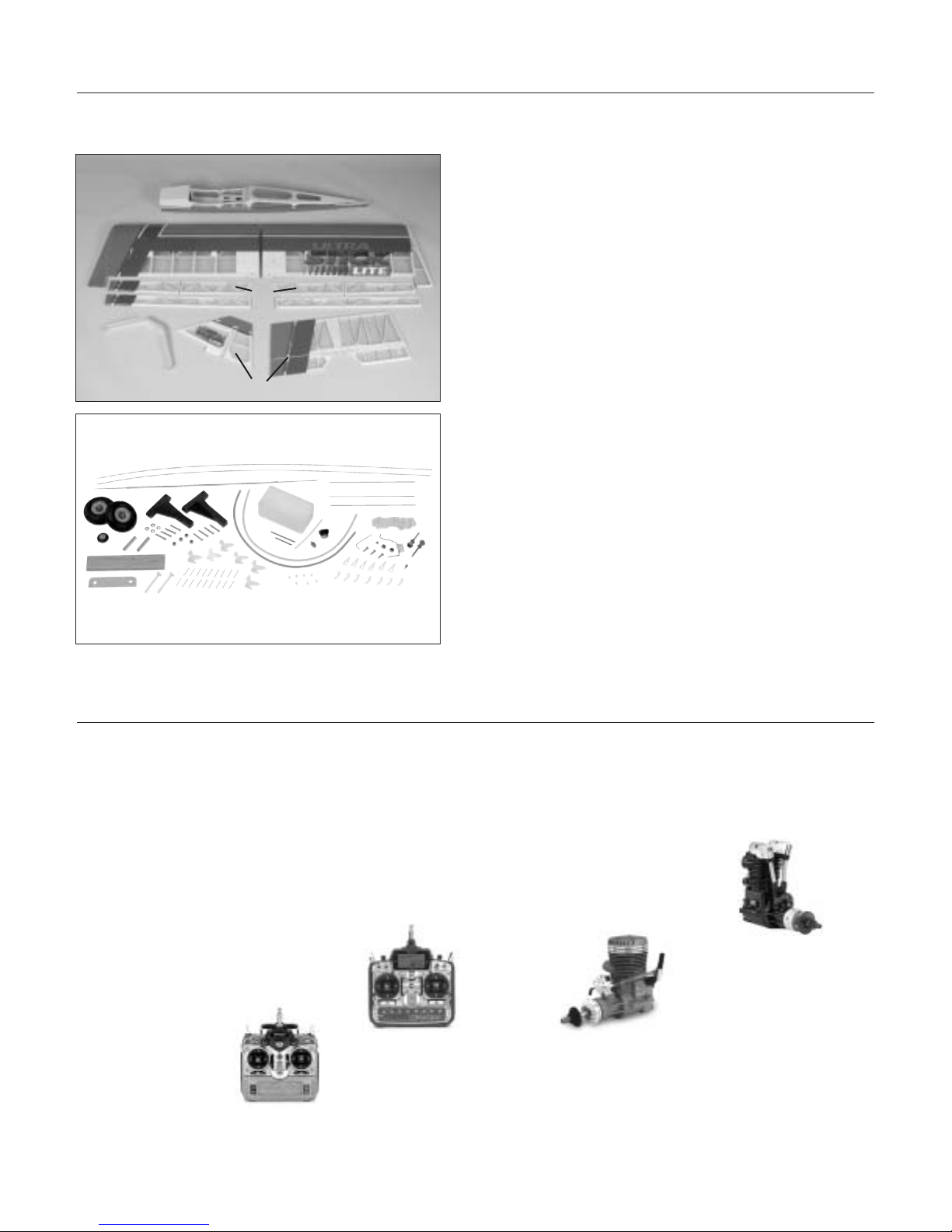
Contents of Kit
Large Parts
A. Fuselage HAN2327
B. Wing Set with Joiner HAN2326
C. Tail Set HAN2328
D. Landing Gear HAN2329
E. Quad-Flap Set HAN2330
Additional Required Equipment
Radio Equipment
• 4-channel radio system (minimum)
(6 if using Quad Flaps)
• 4 standard servos (JRPS537 recommended or
equivalent)
(6 servos required if using Quad Flaps)
Recommended JR™ Systems
• PCM10X
• XP8103
• X-378
• XP662
• XF631
• XF421
Recommended Engines
• 1.08–1.50 2-stroke
• 1.00–1.80 4-stroke
Additional items sold separately
Decal Set (not shown) HAN2331
JR XP8103
JR PCM10X
Saito™
180 Golden Knight AAC
SAIE180 GK
MDS 1.48 Pro (Ring)
MDSE14800
A
B
C
D
E
Page 4

4
Warning
Other Items Needed (not included in the kit)
Additional Required Tools and Adhesives
Tools
• Canopy Scissors
• Drill
• Drill Bit: 1/16", 3/32", 1/8", 7/32", 1/4"
• Flat blade screwdriver
• Hobby knife
• Phillips screwdriver (large and small)
• Pliers
• Square
Adhesives
• 6-minute epoxy
• 30-minute epoxy
• Thin CA (cyanoacrylate) glue
• Thick CA (cyanoacrylate) glue
• CA remover/debonder
• Pacer Z-42 Threadlock
• Canopy glue (RC-56)
• Masking tape (3M blue recommended)
Other Required Items
• Epoxy brushes
• Felt-tipped pen or pencil
• File
• Foam: 1/2"
• Measuring device (ruler, tape measure)
• Mixing sticks for epoxy
• Paper towels
• Petroleum jelly
• Rubbing alcohol
• Sanding bar
• Sandpaper (medium)
• String
• T-pins
• Wax paper
• Propeller (consult engine instructions)
• 537 Standard Servo (JRPS537) or equivalent (4–6)
• 12” Servo Lead Extension (JRPA098) (2)
An RC aircraft is not a toy! If misused, it can cause serious bodily harm and damage to property. Fly only in open
areas, preferably at AMA (Academy of Model Aeronautics) approved flying sites, following all instructions included
with your radio and engine.
• 24” Servo Lead Extension (JRPA102) (2)
• Large Arms w/Screws (JRPA212) (3)
• Extra RX Pack 1100mAh 6V Flat (JRPB4250)
Page 5

5
Before Starting Assembly
Using the Manual
Before beginning the assembly of the Ultra Stick™ Lite, remove each part from its bag for inspection. Closely
inspect the fuselage, wing panels, rudder and stabilizer for damage. If you find any damaged or missing parts,
contact the place of purchase.
If you find any wrinkles in the covering, use a heat gun or covering iron to remove them. Use caution while
working around areas where the colors overlap to prevent separating the colors.
This manual is divided into sections to help make assembly easier to understand and to provide breaks between
each major section. In addition, check boxes are provided to help you to keep track of each step completed.
Steps with two boxes indicate that the step will require repeating, such as for a right or left wing panel, two
servos, etc. Remember to take your time and follow the directions.
Warranty Information
Horizon Hobby, Inc. guarantees this kit to be free from defects in both material and workmanship at the date of
purchase. This warranty does not cover any parts damage by use or modification. In no case shall Horizon Hobby's
liability exceed the original cost of the purchased kit. Further, Horizon Hobby reserves the right to change or modify
this warranty without notice.
In that Horizon Hobby has no control over the final assembly or material used for the final assembly, no liability
shall be assumed nor accepted for any damage of the final user-assembled product. By the act of using the product,
the user accepts all resulting liability.
Once assembly of the model has been started, you must contact Horizon Hobby, Inc. directly regarding any warranty
question that you have. Please do not contact your local hobby shop regarding warranty issues, even if that is where
you purchased it. This will enable Horizon to better answer your questions and service you in the event that you may
need any assistance.
If the buyer is not prepared to accept the liability associated with the use of this product, the buyer is advised to
return this kit immediately in new and unused condition to the place of purchase.
Horizon Hobby
4105 Fieldstone Road
Champaign, Illinois 61822
(217) 355-9511
www.horizonhobby.com
Page 6
6
Section 1: Conventional Wing Assembly
Required Parts
• Left wing panel with aileron and hinges
• Right wing panel with aileron and hinges
Required Tools and Adhesives
• Paper towels
• Instant thin CA glue
• CA remover/debonder
• T-pins (one for each hinge)
• Hobby knife with #11 blade
Before beginning construction, decide what style of wing
is desired (conventional or quad-flap) and what type of
engine will be mounted on the model. The conventional
aileron wing will be presented in this section. Each
aileron will be controlled by its own servo. You will
need two servos when you begin Section 3.
For a standard wing configuration, we recommend a
servo that has 40 ounce inch of torque or greater,
such as the JR™ 537 servo that now comes standard with
JR radio systems. The JR 531 or 8101 servos are also
excellent to use for aileron servos in the wing.
Note: The control surfaces, including the
ailerons, flaps, elevator and rudder, come with
the hinges installed, but the hinges are not
glued in place. It’s imperative that you use a
high quality thin CA glue to properly adhere
the hinges and control surfaces in place.
Step 1
Carefully remove one of the wing panels from its
protective plastic. Save the plastic, as it will be used
later in Section 2 to protect the wing panel surface
from epoxy smears. Remove the aileron from the wing
panel. Note the position of the hinges.
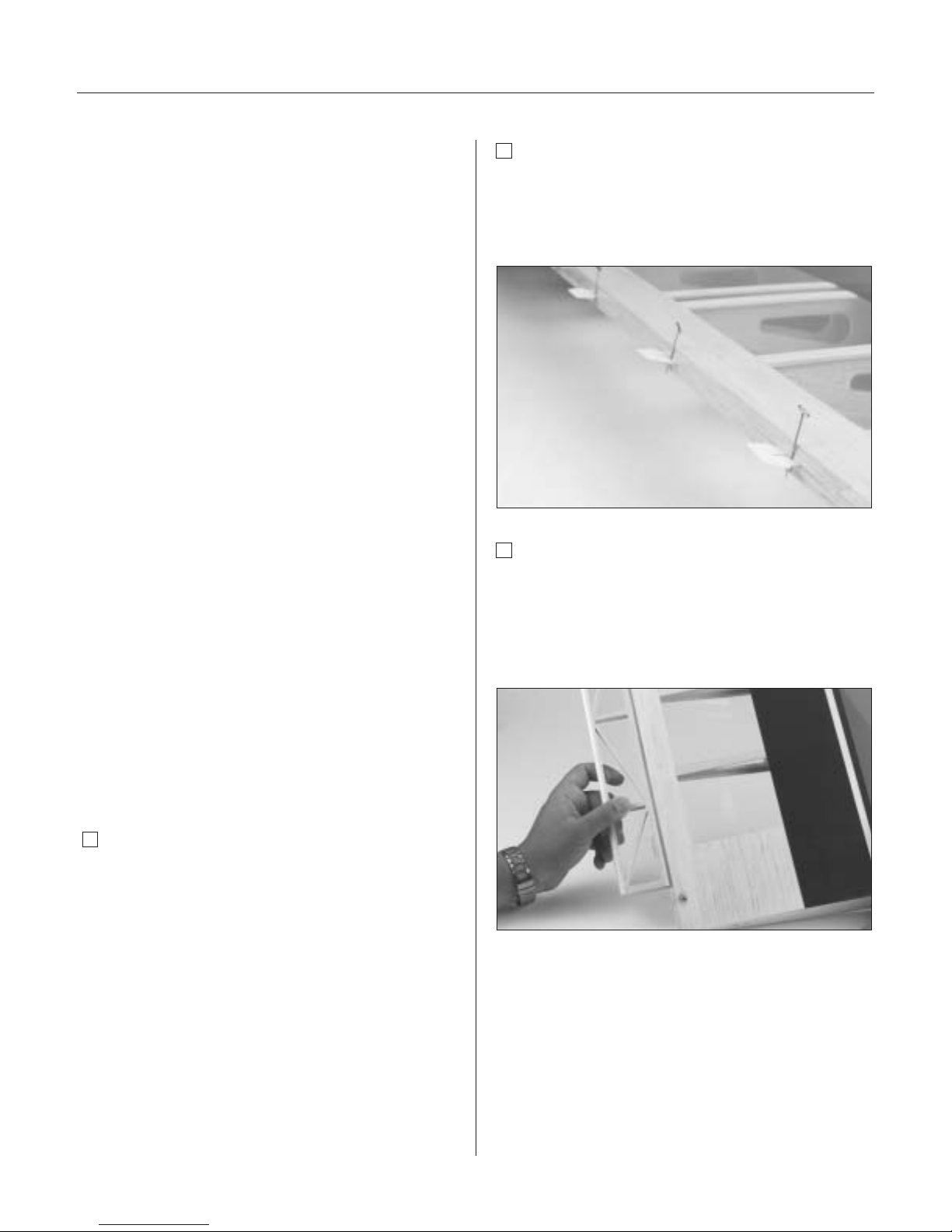
Step 2
Remove each hinge from the wing panel and place a
T-pin in the center outside edge of each hinge. Slide
each hinge into the wing panel until the T-pin is snug
against the wing.
Step 3
Slide the aileron onto the wing until there’s only a slight
gap (approx. 1/32" or less). The hinges are now centered
on the wing panel and aileron. Remove the T-pin and
snug the aileron against the wing panel. This will
ensure that the hinges are centered.
Note: The hinge is constructed of a special
material that allows the CA to wick (or
penetrate) and distribute throughout the hinge,
securely bonding it to the wood structure.
Before applying CA, make sure the aileron
moves freely without binding on the wing.
Page 7
Section 1: Conventional Wing Assembly
7
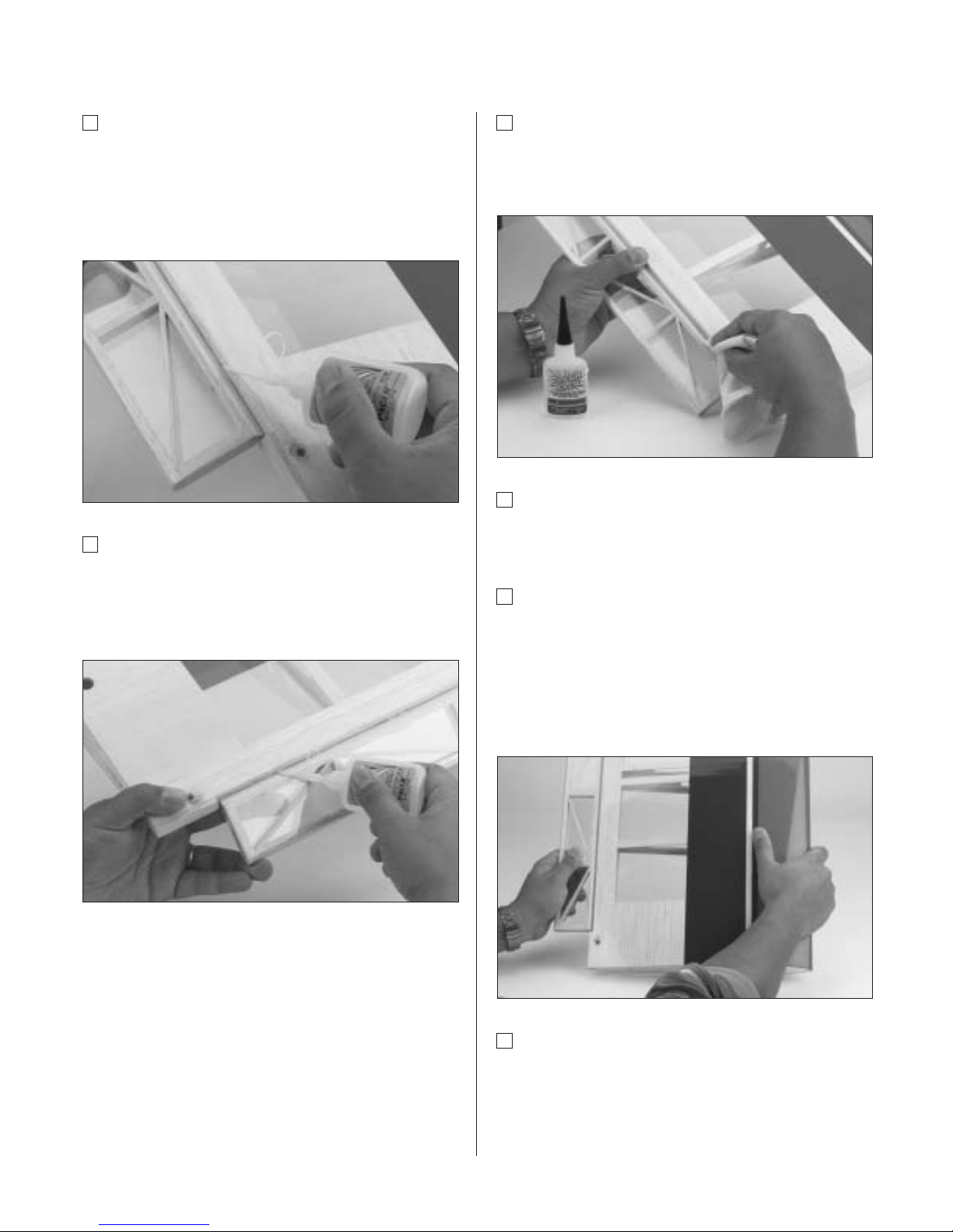
Step 4
Deflect the aileron and completely saturate the hinge with
thin CA glue. The aileron’s front surface should lightly
contact the wing during this procedure. Ideally, when the
hinge is glued in place, a 1/32" gap or less will be
maintained throughout the length of the aileron.
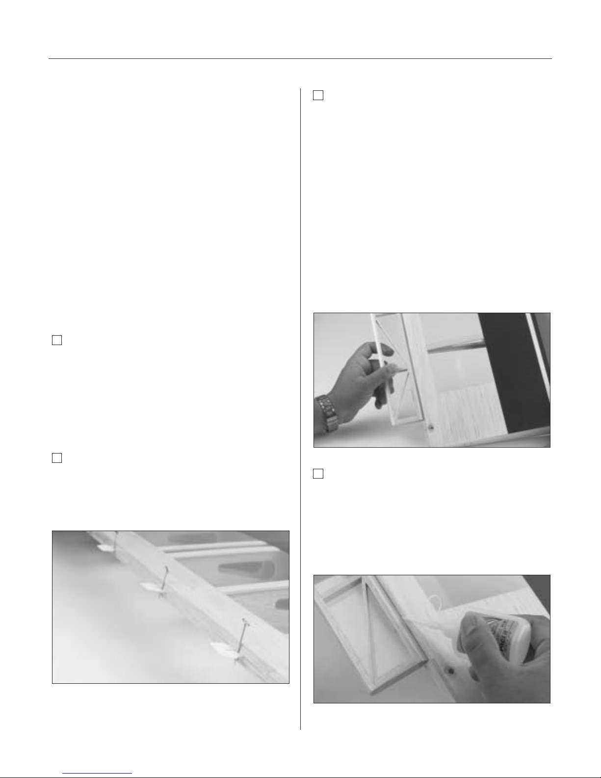
Step 5
Turn the wing panel over and deflect the aileron in the
opposite direction from the previous step. Again apply
thin CA glue to each aileron hinge, making sure the CA
penetrates into both the aileron and the wing.
Step 6
Using CA remover/debonder and a paper towel,
remove any excess CA glue that may have accumulated
on the wing or in the aileron hinge area.
Step 7
Repeat Steps 1 through 6 for the opposite wing half
before moving on to Step 8.
Step 8
After both ailerons are securely hinged, firmly grasp
the wing and aileron to check that the hinges are
securely glued and cannot be pulled apart. To do this,
apply medium pressure to try to separate the aileron
from the wing, using caution to be certain you don’t
crush the wing structure.
Step 9
Move the aileron up and down to “work in” the hinges
and check for proper movement.
Page 8
8
Section 1a: Quad-Flap Wing Assembly
Required Parts
• Left wing aileron/flap
• Right wing aileron/flap
• Left wing panel with aileron and hinges
• Right wing panel with aileron and hinges
Required Tools and Adhesives
• Sealing iron • Paper towels
• Instant thin CA glue
• CA remover/debonder
• T-pins (one for each hinge)
• Hobby knife with #11 blade
Note: The procedure for hinging the
flap/aileron in each wing panel is the same as
described for the conventional wing.
Step 1a
Locate the plastic bag containing the flap/aileron
pieces for each wing panel and remove from the
package. Carefully remove one of the wing panels from
the protective plastic bag. Save the plastic bag for use
in Section 2. Remove the conventional aileron from the
wing panel.
Step 2a
Remove the hinges from the wing panel and place a
T-pin in the center outside edge of each hinge. Slide
each hinge into the wing panel until the T-pin is snug
against the wing.
Step 3a
Slide the aileron and flap control surface onto the wing
panel until there’s only a slight gap (approximately 1/32").
The hinges are now centered on the wing panel and the
control surfaces. Remove the T-pins and snug each
control surface to the wing panel. This will ensure the
hinges are centered.
Note: The hinge is constructed of a special
material that allows the CA to wick (or
penetrate) and distribute throughout the hinge,
securely bonding it to the wood structure.
Before applying CA, make sure the flap and
aileron move freely without binding on the
wing or with each other.
Step 4a
Deflect the aileron and flap and completely saturate each
hinge with thin CA glue. The aileron and flap’s front
surface should lightly contact the wing during this
procedure. Ideally, when the hinges are glued in place,
a 1/32" gap or less will be maintained throughout the
length of the aileron and flap.
Page 9
Section 1a: Quad-Flap Wing Assembly
9
Step 5a
Turn the wing panel over and deflect the aileron and flap
in the opposite direction from the previous step. Apply
thin CA glue to each aileron hinge, making sure the CA
penetrates into the aileron, flap and the wing.
Step 6a
Using CA remover/debonder and a paper towel, remove
any excess CA glue that may have accumulated on the
wing aileron or flap hinge area.
Step 7a
Repeat Steps 1A through 6A for the opposite wing panel.
Step 8a
After both the aileron and flap control surfaces are
securely hinged, firmly grasp the wing, flap, and aileron
to check that they are securely glued and cannot be
pulled apart. To do this, apply medium pressure to try to
separate the control surfaces from the wing. Use caution
to be certain you don’t crush the wing structure.
Step 9a
Move the control surfaces up and down to “work in” the
hinges and check for proper movement.
Important: If any binding has developed
between the control surfaces, it must be
removed. You may have to trim away some
covering or balsa to make each control
surface move freely.
Page 10
10
Section 2: Joining the Wing Halves
Required Parts
• Right/left wing panels
• Plastic wing bags (optional)
• Wing joiner brace
Required Tools and Adhesives
• 30-minute epoxy • Epoxy brush
• Mixing stick • T-pin
• Masking tape • Hobby knife
• Rubbing alcohol • Paper towels
• Wax paper • Ruler
• Pencil
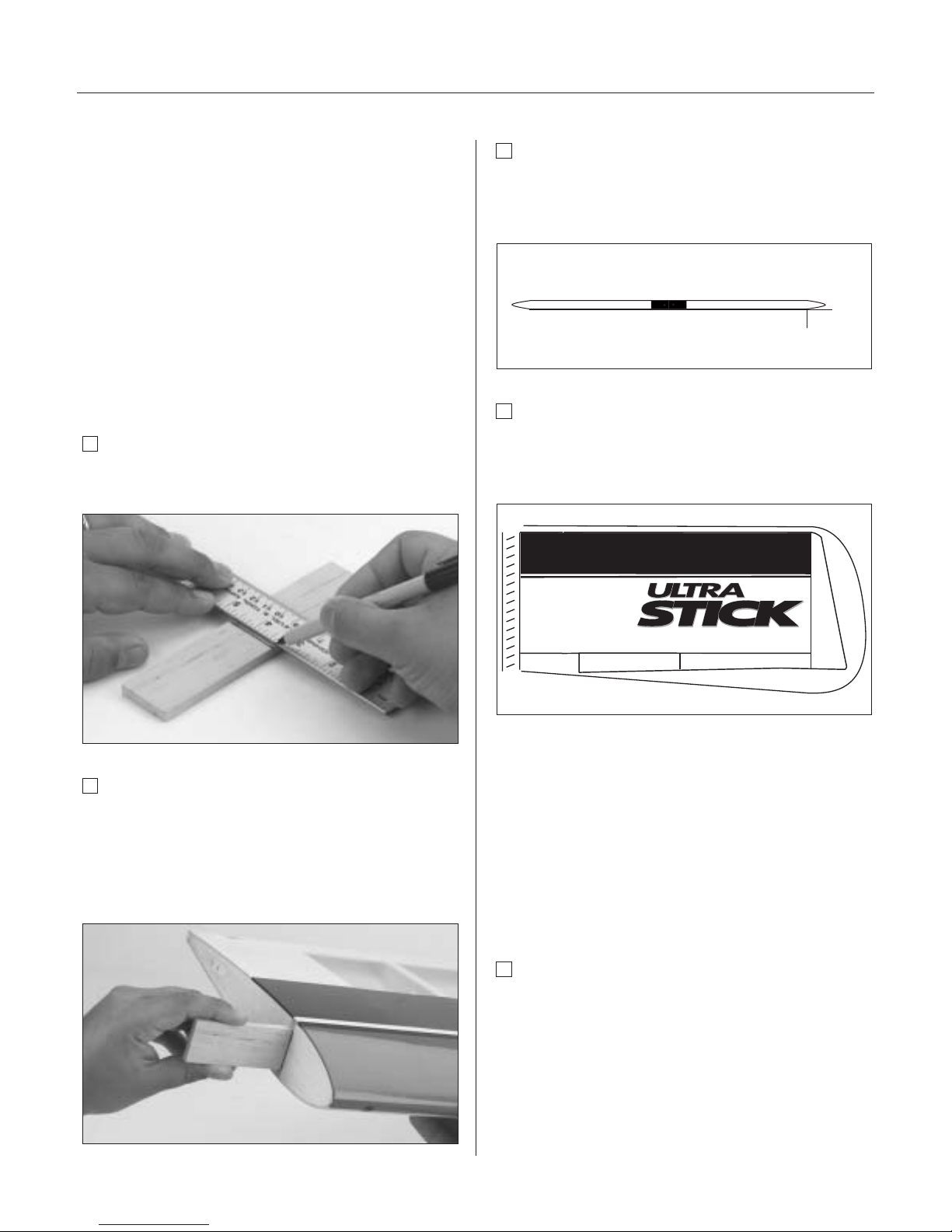
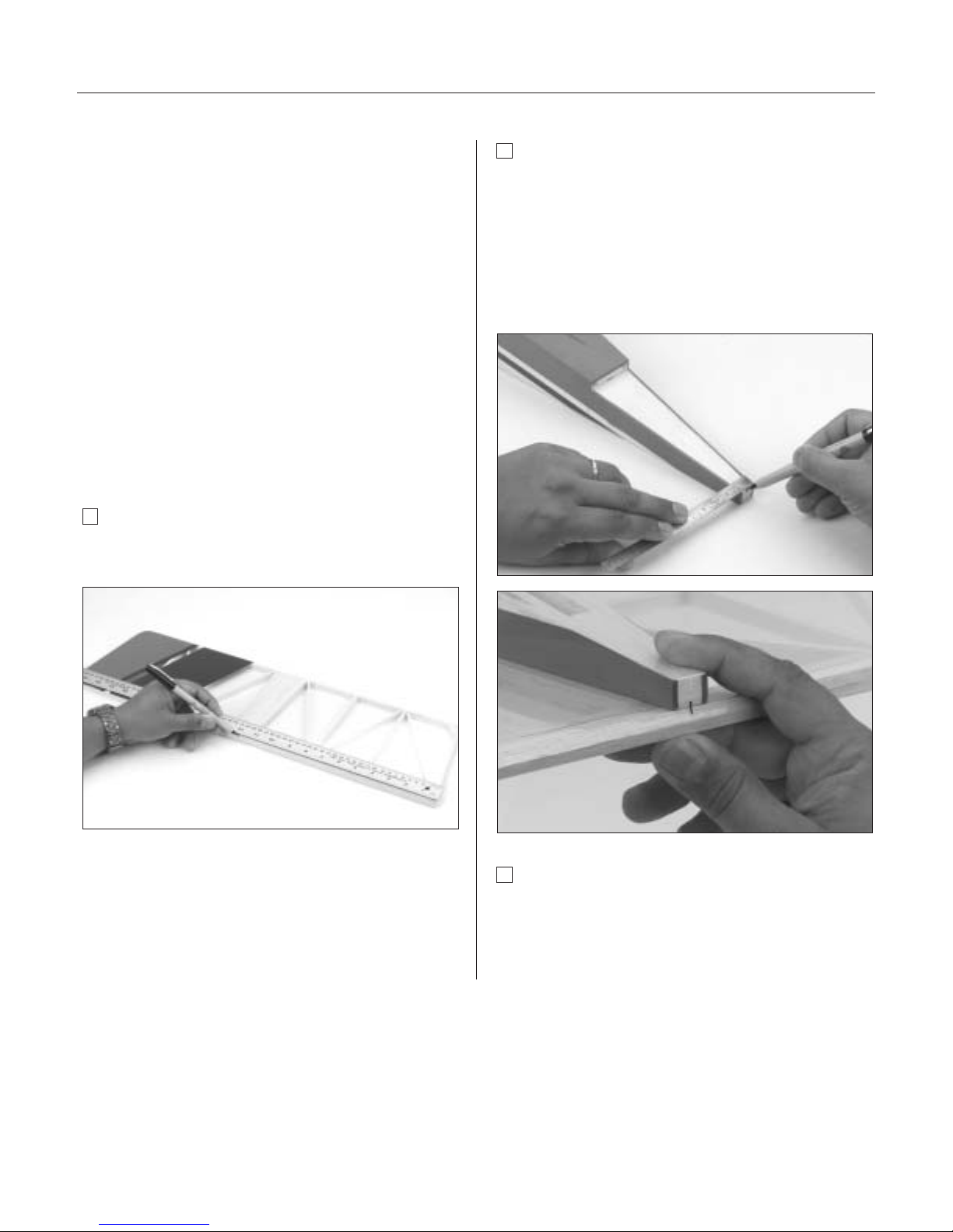
Step 1
Locate the wing joiner. Using a ruler, determine the center
of the brace and mark it with a pencil.
Step 2
Trial fit the wing joiner into one of the wing panels. It
should insert smoothly up to the centerline marked in
Step 1. Now slide the other wing panel onto the wing
joiner until the wing panels meet. If the fit is overly tight,
it may be necessary to sand the wing joiner.
Step 3
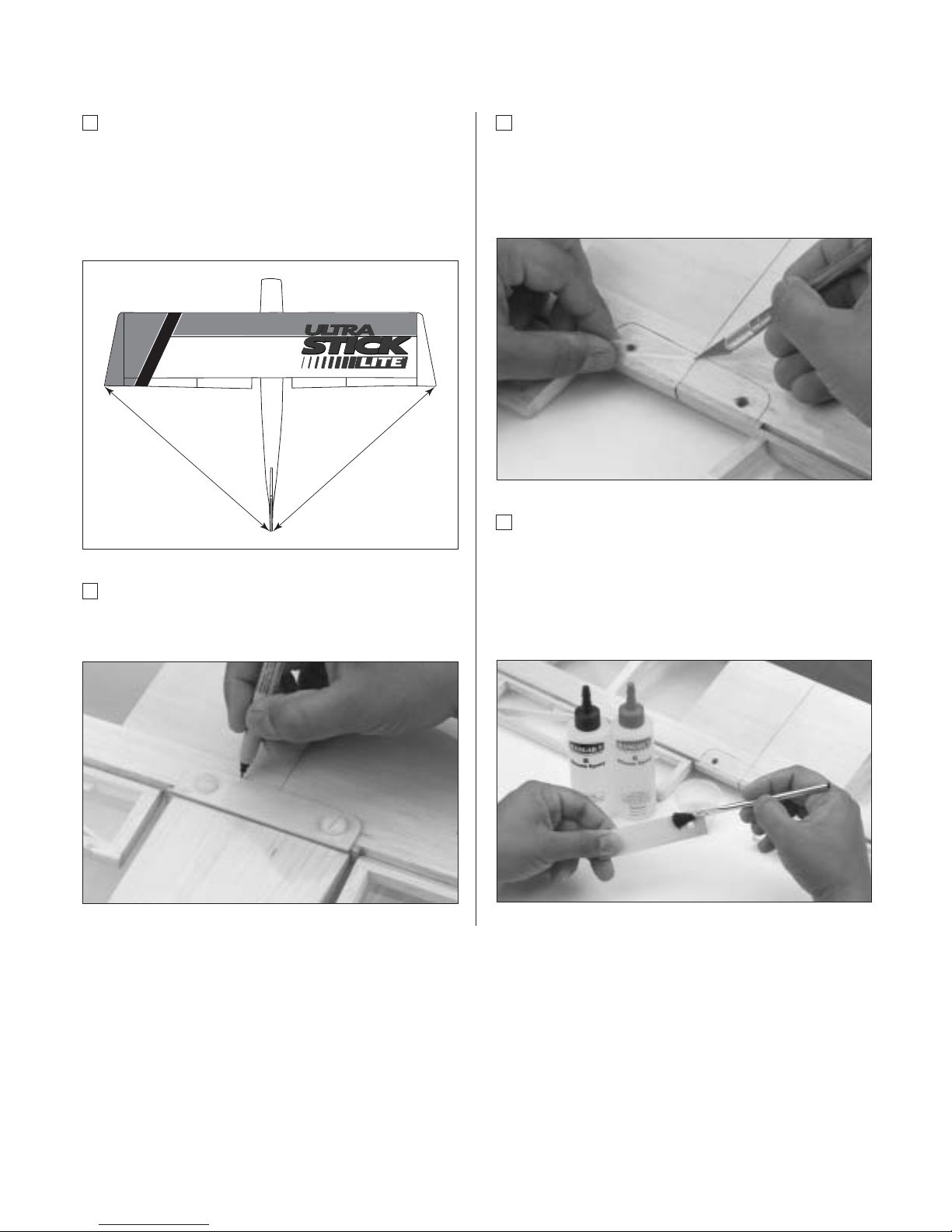
The Ultra Stick™ Lite is designed with "0" dihedral. Place
the wing on a large flat surface. The spar, (high point of
the wing), should be flat on the surface.
Step 4
Separate the wing halves and remove the wing joiner.
Once you’re satisfied with the trial fit of the wing panels,
you can prepare to epoxy the wing panels together.
Note: Use the plastic wing bags as a means
of keeping epoxy from smearing on the wings.
Just slip one on each panel and use masking
tape to hold them in place.
Important: Read through each of the
remaining steps of this section before
proceeding to epoxy the wing halves together.
Step 5
Mix approximately 1 ounce of 30-minute epoxy.
Note: It’s extremely important to use plenty of
epoxy when gluing the wing halves together.
0"
at last rib without
tip section
Page 11
Section 2: Joining the Wing Halves
11
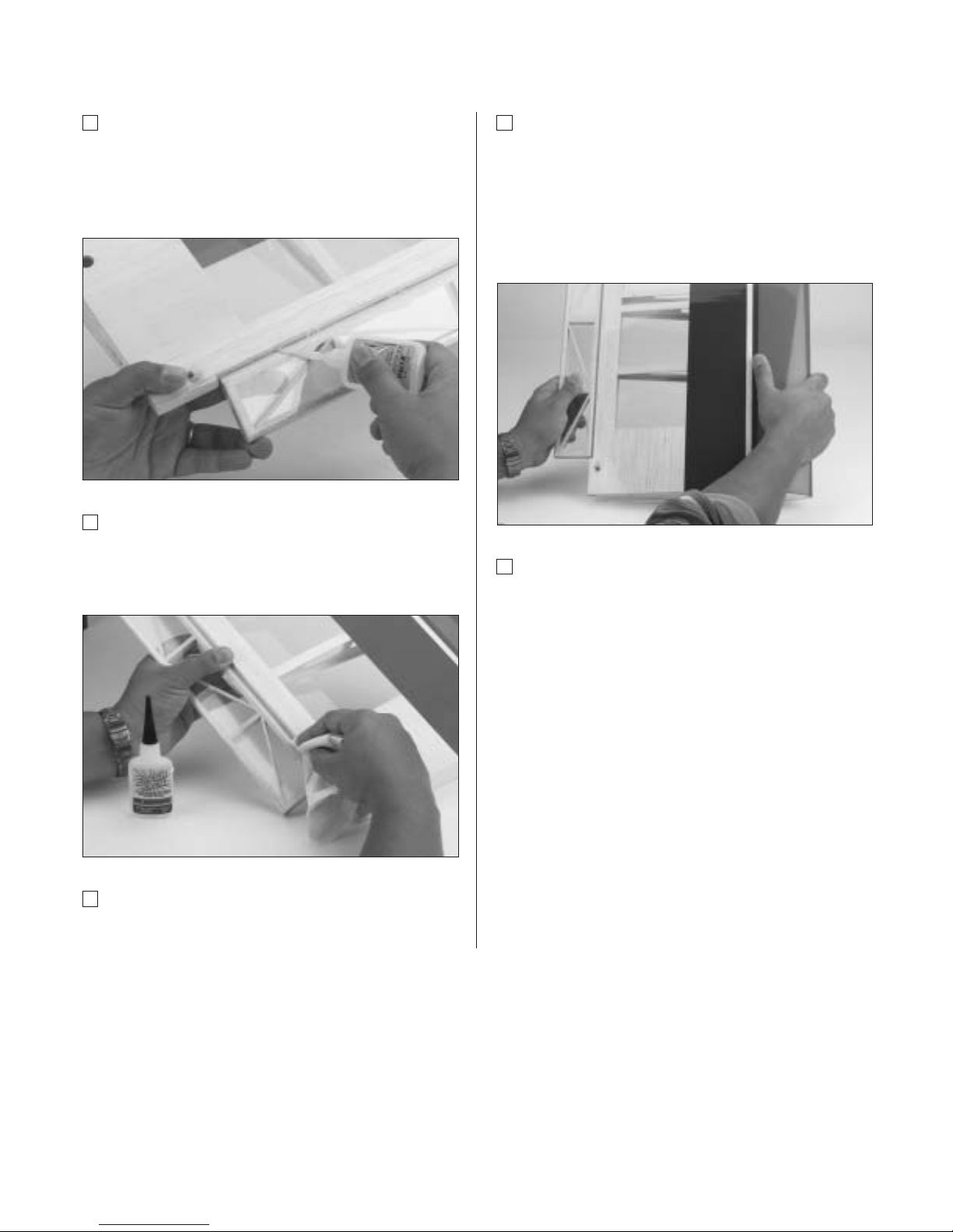
Step 6
Place one wing half right side up on a flat work surface.
Using an epoxy brush, smear a generous amount of
epoxy into the wing joiner cavity in the wing panel.
Note: It’s helpful to put wax paper under
the wing.
Step 7
Coat one half of the wing joiner with epoxy up to the
pencil line drawn in Step 8. Install the epoxy-coated
half of the wing joiner into the wing joiner cavity up to
the marked centerline. Any excess epoxy can be cleaned
up with rubbing alcohol and paper towels.
Note: You will need to mix an additional
1–2 ounces of epoxy to complete the wing
joining process.
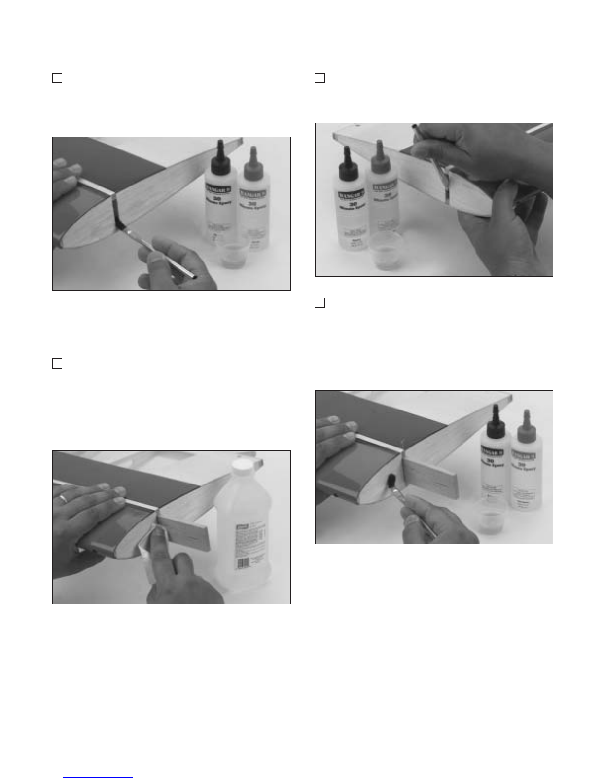
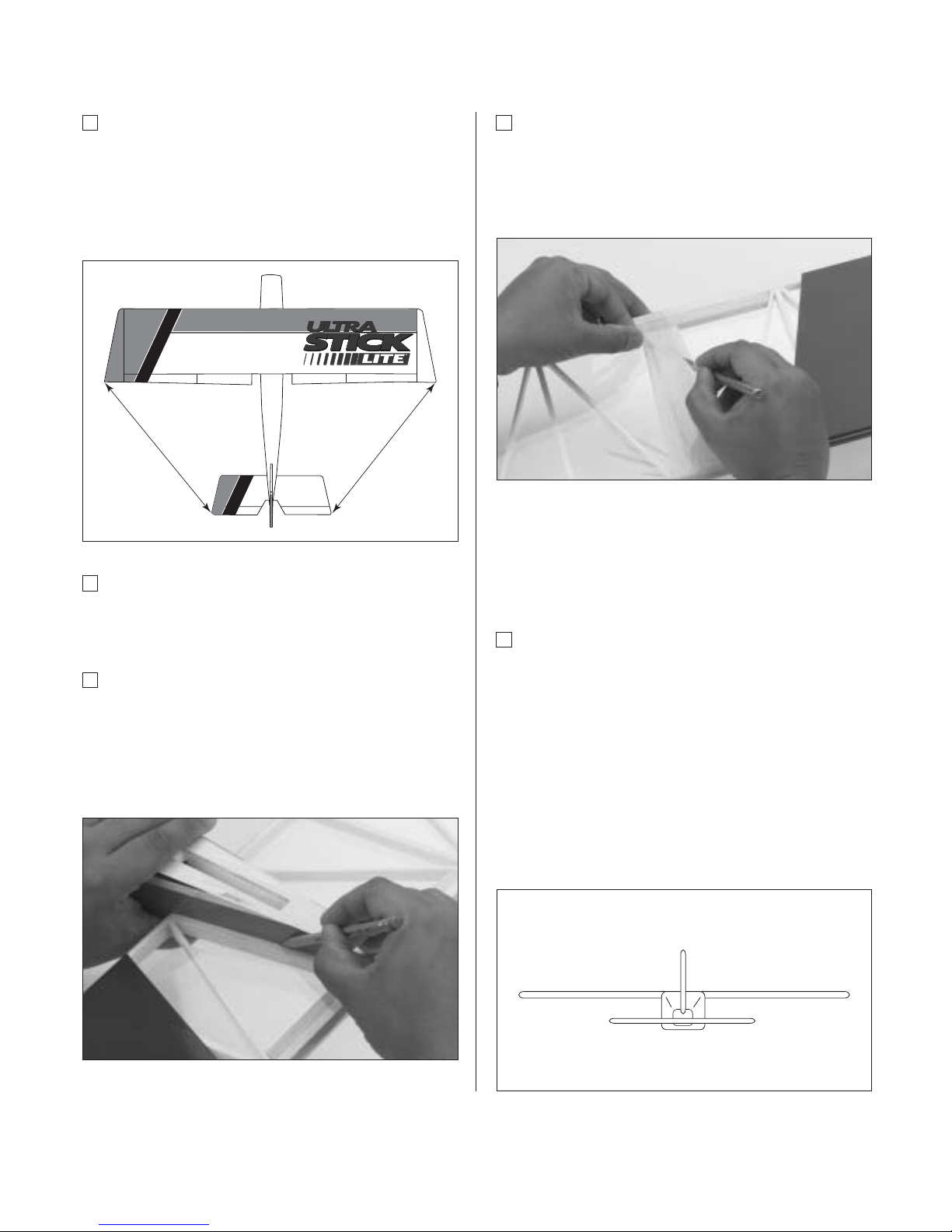
Step 8
Apply a generous amount of epoxy into the wing joiner
cavity of the other wing panel.
Step 9
Install a T-pin into the wing joiner at the center mark. This
will allow you to keep the brace in the center of the wing
when joining the two wing halves. Next, apply epoxy to all
sides of the exposed area of the wing joiner and uniformly
coat both wing roots with epoxy.
Page 12
12
Section 2: Joining the Wing Halves
Step 10
Carefully slide the two wing halves together and firmly
press them together, allowing the excess epoxy to run out.
Check to make sure the wing panels align properly. Wipe
any excess epoxy away with rubbing alcohol and paper
towels. The plastic wing bag can be removed from the
wing halves after the epoxy has been applied.
Note: It’s helpful to use wax paper underneath
the wing center while the epoxy is curing to
prevent excess epoxy from adhering to the
work surface area.
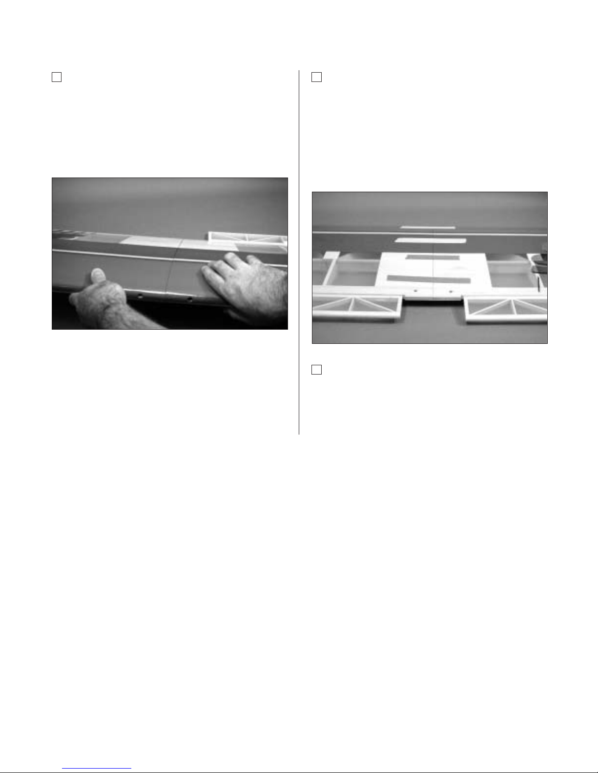
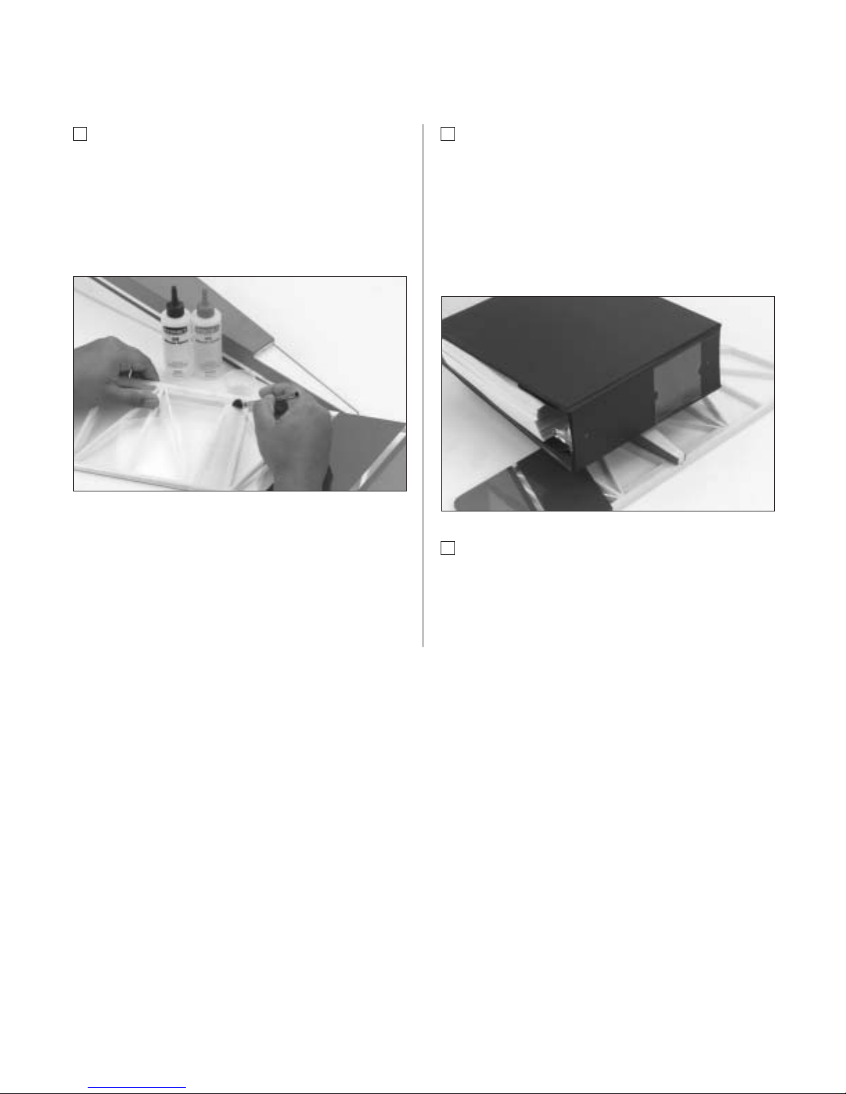
Step 11
Apply masking tape at the wing joint to hold the wing
halves together securely. Place the wing right side up on
a flat surface. With the wing lying flat on a surface without
any dihedral, apply more masking tape to the wing center
joint and recheck that the wing remains flat. Also make
sure the wing halves are still properly aligned. Allow the
wing joint epoxy to cure completely (overnight).
Step 12
Once the epoxy has cured completely, remove the
masking tape.
Page 13
Section 3: Aileron/Flap Servo Installation
13
Required Parts
• Assembled wing
• 12" Servo extension (2)
(2 additional 24" for quad-flap configuration
wing)
• Standard size servos with mounting hardware (2)
(4 for quad-flap configuration)
Note: The flap servo must be reversed if using a
Y-harness for flaps.
Required Tools and Adhesives
• Hobby knife • Needle-nose pliers
• Drill • Drill Bit: 1/16"
• Masking tape • Pencil
• String with weight on end
• Phillips screwdriver (medium)
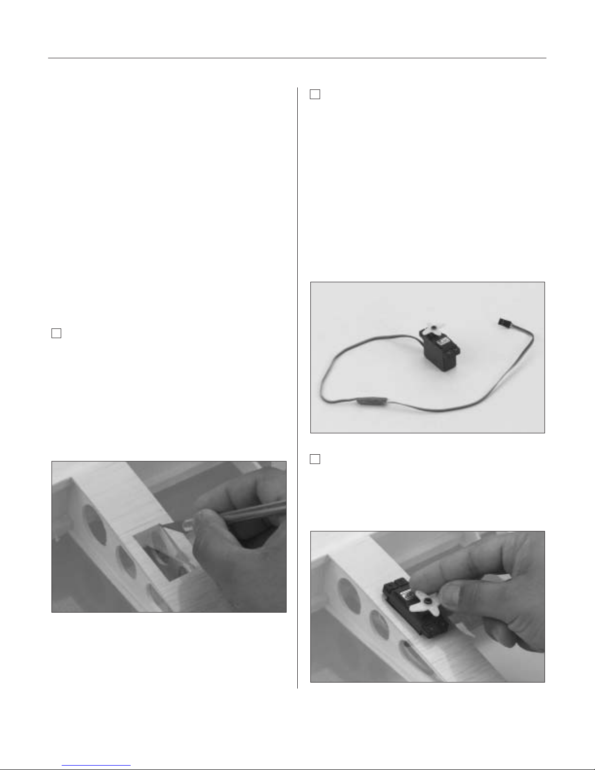
Step 1
Locate the servo openings in the bottom of each of the
wing halves. Use a sharp hobby knife to trim away the
covering over the openings. If you’re building the
conventional wing, you will only cut out the openings
that are closest to the wing root for the aileron servos.
If you build the quad-flap wing, trim away the covering
on all four servo openings in the wing. Use care not to
cut away too much of the covering.
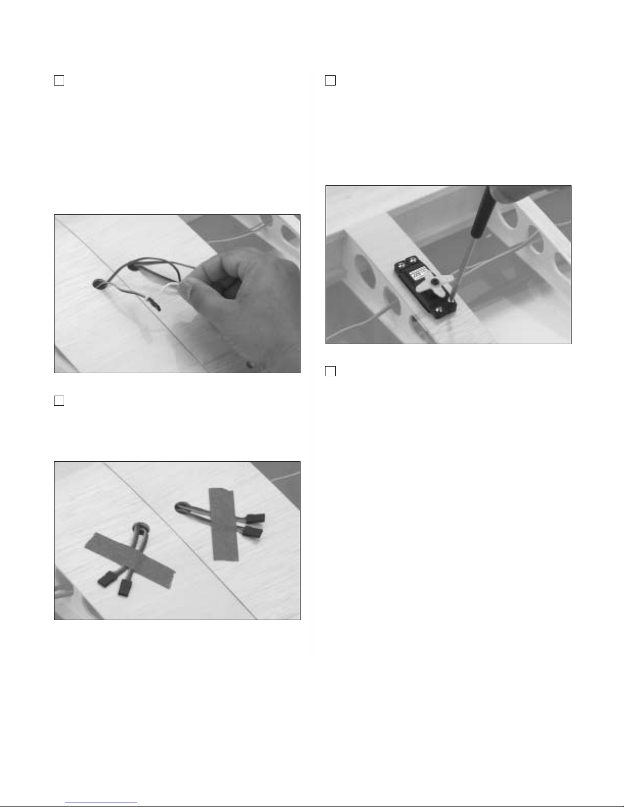
Step 2
Install the recommended servo hardware supplied with
your radio system onto your servos, (grommets and
eyelets). Install 12" servo extensions on the flap servo
lead and 24" extensions on the aileron servo leads.
Secure the connectors with either masking tape or a
commercial connector that prevents the servo lead
connections from becoming disconnected.
Hint: It’s always a good idea to tape or secure
the servo connectors and servo extension
together to prevent the wires from becoming
unplugged inside the wing.
Step 3
Trial fit the servo into the servo opening. Depending upon
the type of servo installed, some trimming may be
required. Note that the servo is orientated so the servo
output shaft is closer to the trailing edge of the wing.
Page 14

14
Section 3: Aileron/Flap Servo Installation
Step 4
With the servo in place, mark the location of the servo
screws and then remove the servo.
Step 5
Using a 1/16" drill bit, drill the servo screw locations
marked in Step 4.
Step 6
Repeat the procedure for the other servo(s).
Step 7
Before mounting the servos in the wing, it’s suggested
that the servo extensions be run through the wing and
out the opening near the root rib.
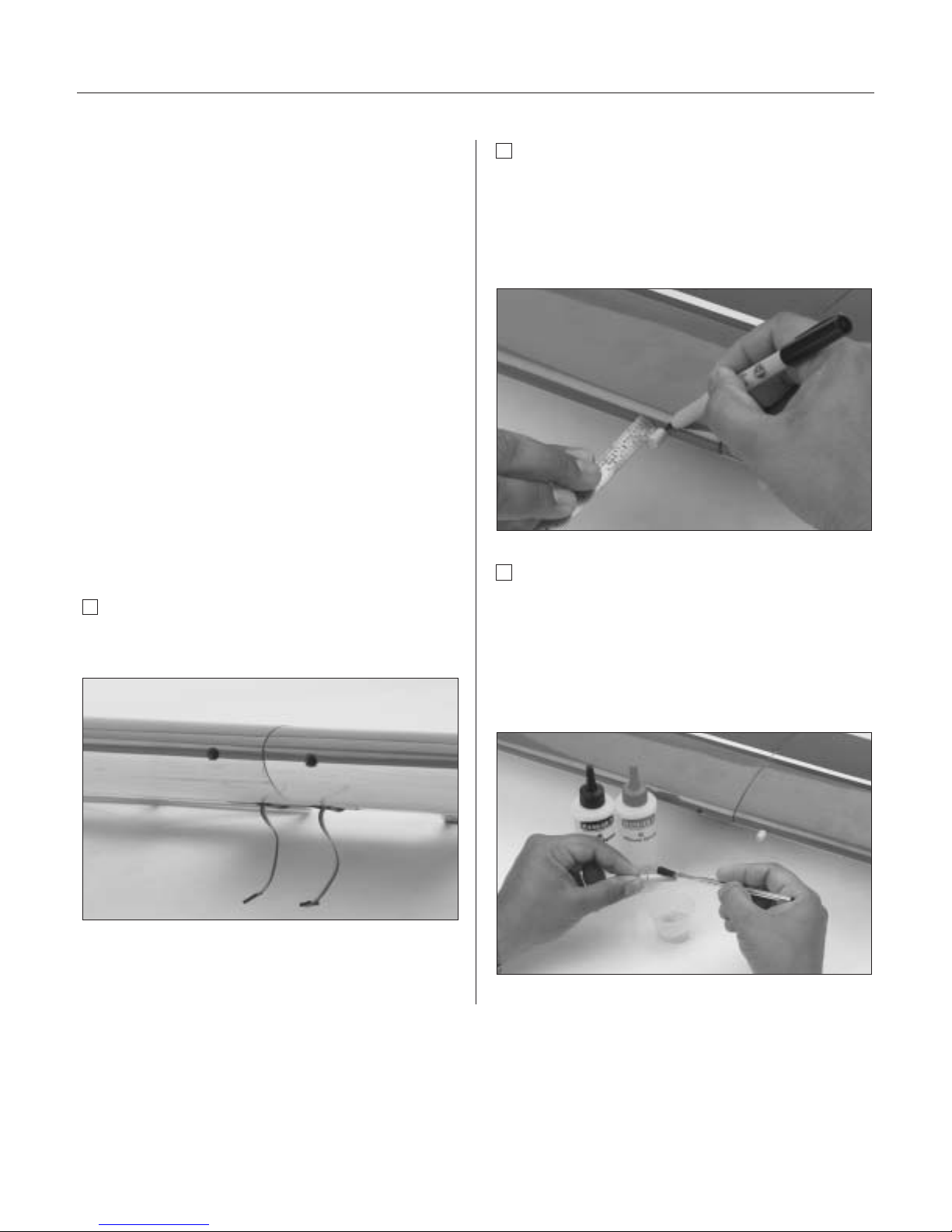
Step 8
Locate the two circular servo lead exits near the center
of the wing bottom. Using a sharp hobby knife, trim
away the covering to expose the openings, making sure
to use caution so you don’t cut into the wing sheeting.
Step 9
To thread the ser vo lead extensions/ser vo leads
through the wing, we suggest using a 24” piece of string
with a weight attached (such as one of the wheel collars
in the kit). Thread it from the servo opening down
through the wing structure and out the exit opening
at the center of the wing.
Page 15
Section 3: Aileron/Flap Servo Installation
15
Step 10
Once the string is threaded though the wing, you can
fish it out with your fingers or let the weight drop out
the opening. Tape each end to the wing to keep it from
falling back into the opening. When you’re ready to
thread the servo extension and servo lead through the
wing, simply tie the string to the extension and carefully
thread them through the wing by pulling the string/lead
through the openings.
Step 11
Tape the lead to the wing to keep it from falling back
into the opening. It may be easier if you thread one
servo lead at a time.
Step 12
Securely fasten the servo in the opening with four of
the servo mounting screws supplied with your radio
system. We suggest you mark which lead is an aileron
lead and which is a flap lead. Apply masking tape to
the appropriate lead and mark either "F" for flap or
"A" for aileron.
Step 13
Repeat the procedure for the other servo(s).
Note: It was intended to have each servo
connected to a specific channel in the receiver,
however you can use a Y-harness to connect
two ailerons to one aileron channel or two
flaps to one flap channel, which will require
one of the flap servos to be a reversed servo.
This will reduce your programming options.
Please refer to Section 19 for computer radio
programming for the Ultra Stick™ Lite.
Installing the linkages and control horns to the
ailerons/flaps will be addressed later in the manual.
Page 16
16
Section 4: Bolting the Wing to the Fuselage
Required Parts
• Fuselage • Wing
• Wing-bolt plate • Wing bolts
• Leading edge wing dowels
Required Tools and Adhesives
• Hobby knife • File (round)
• Flat screwdriver • Felt-tipped pen/pencil
• 6-minute epoxy • Rubbing alcohol
• Paper towels
• Ruler (36” or tape measure)
Note: Your Hangar 9
®
Ultra Stick™ Lite
comes from the factory with two predrilled
holes in the leading edge of the wing for the
alignment dowels, and two predrilled holes for
the wing hold down bolts. The Ultra Stick Lite
comes with the wing bolt T-nuts preinstalled
in the fuselage.
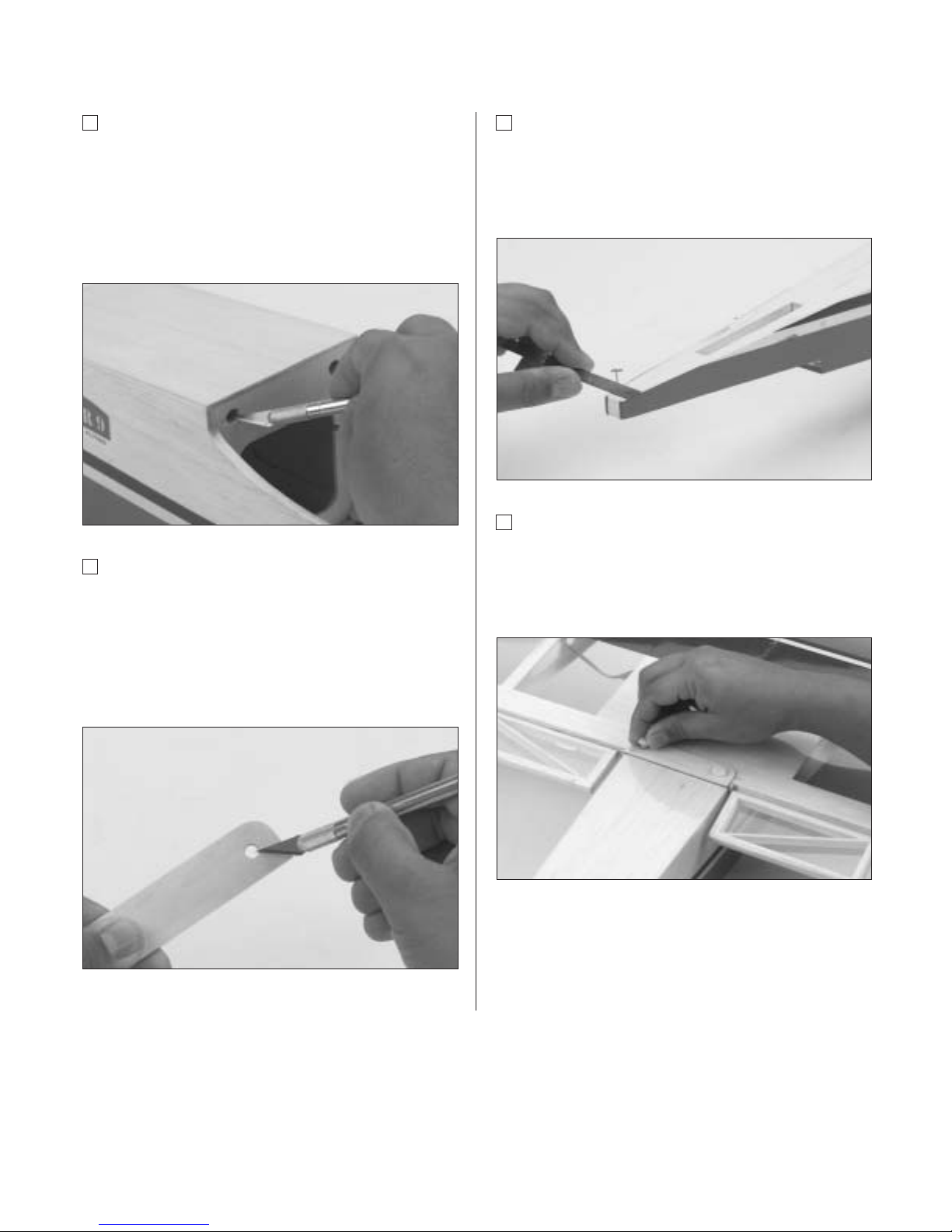
Step 1
Locate the predrilled leading edge dowel holes located
on both sides of the center joint of the wing.
Step 2
Locate and trial fit the leading edge wing dowels into the
holes in the leading edge. There should be approximately
1/2" of dowel protruding from the leading edge of the
wing, (trim the dowels as necessary). Mark each dowel
where it exits the leading edge of wing.
Step 3
Remove the wing dowels and mix about 1/2 ounce of
6-minute epoxy. Use a generous amount of epoxy in the
leading edge holes and on the portion of the dowels that
will be inserted into the wing. Insert dowels into the wing
and wipe off any excess epoxy. Set the wing aside and
allow epoxy to cure.
Page 17
Section 4: Bolting the Wing to the Fuselage
17
Step 4
After the epoxy has cured for the leading edge alignment
dowels, trial fit the wing to the fuselage by inserting the
dowels into the former in front of the wing saddle of the
fuselage. If the wing dowel fit is too tight, carefully
enlarge the holes in the former just enough to get the
wing dowels inserted.
Step 5
Locate the wing-bolt hold-down plate. Note the wing-bolt
hold-down plate has the holes already drilled out for the
wing bolts. The holes in the wing bolt plate have the
same spacing as the preinstalled blind nuts in the
fuselage. Carefully remove the covering over the
predrilled openings using a sharp hobby knife.
Step 6
Using a ruler and felt-tipped pen, measure and mark
the center of the fuselage at the tail end just above the
horizontal stabilizer mounting saddle. Insert a T-pin
at the mark you made.
Step 7
Insert the wing bolts through the wing-bolt plate (covered
side up) and insert the bolts through the wing-bolt holes
in the wing. Install the wing onto the fuselage and snug
the wing bolts down finger tight.
Page 18
18
Section 4: Bolting the Wing to the Fuselage
Step 8
Check the alignment of the wing by measuring the
distance from the wing tip to the T-pin you installed in
Step 6. Make sure to measure from the same spot on
both wing tips. Once satisfied with alignment, tighten
the wing bolts securely.
Step 9
Using a felt-tipped pen or pencil, carefully mark around
the outside of the wing bolt plate.
Step 10
Remove the wing from the fuselage and using a sharp
hobby knife, carefully trim away the covering on the wing
1/8" inside the lines you marked for the wing-bolt plate.
Be sure to avoid cutting into the balsa wood.
Step 11
Mix approximately 1/4 ounce of 6-minute epoxy
and glue the wing hold-down plate onto the wing.
Wipe off any excess epoxy and remove any epoxy
from the wing-bolt holes. Allow the epoxy to
completely cure before proceeding.
Page 19
Section 5: Horizontal Stabilizer Installation
19
Required Parts
• Horizontal stabilizer • Fuselage
• Assembled wing
Required Tools and Adhesives
• Hobby knife • Ruler
• Felt-tipped pen • Pencil
• 30-minute epoxy • Paper towels
• Rubbing alcohol • Mixing stick
• Epoxy brush • Masking tape
Note: Before assembling the tail, be sure the
elevator and the CA hinges are removed from
the horizontal stabilizer. The hinges and
elevator will be installed later.
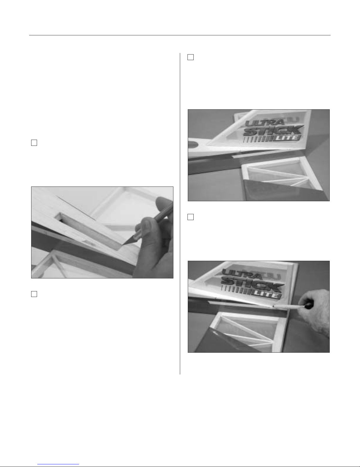
Step 1
Measure and mark the center of the horizontal stabilizer
on its trailing edge.
Step 2
On the bottom of the aft end of the fuselage is a saddle
cut out for the horizontal stabilizer to be mounted. Make
a center mark on the back of the saddle and place the
horizontal stabilizer into the horizontal stabilizer saddle.
Align the two marks you made. Tape the leading edge
and trailing edge of the horizontal stabilizer to the
fuselage to secure it for now.
Step 3
Install the wing onto the fuselage.
Page 20
20
Section 5: Horizontal Stabilizer Installation
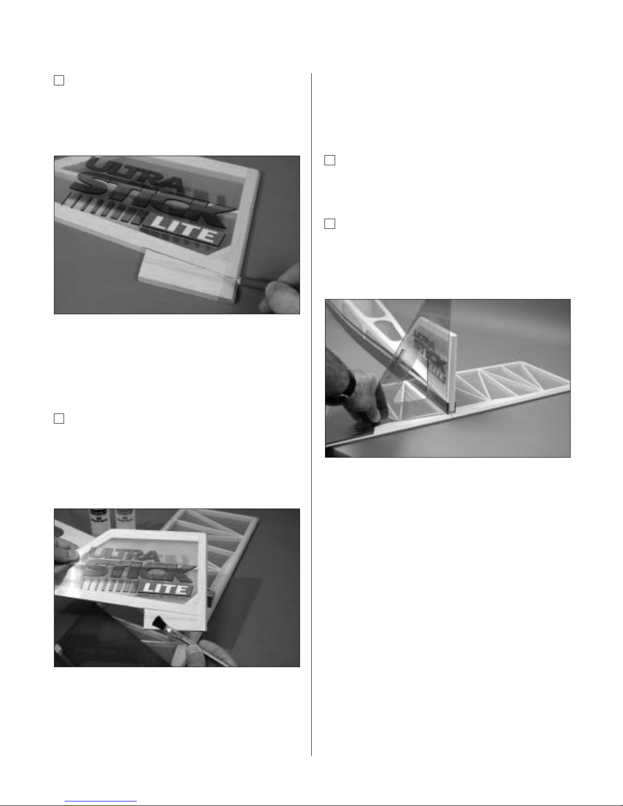
Step 4
With the fuselage and horizontal stabilizer resting on a flat
surface, align the horizontal stabilizer by measuring from
fixed points on the wing to the outside of the trailing edge
tip of the horizontal stabilizer. Be sure that the trailing
edge of the horizontal stabilizer stays on its center mark.
Step 5
Adjust the stabilizer until you have an equal distance on
both the right and left sides of the stabilizer to the wing.
Step 6
When you’re satisfied with the alignment of the horizontal
stabilizer to the wing, carefully mark the position with
a pencil at the junction where the horizontal stabilizer
meets the fuselage. The pencil should leave a slight
indentation in the covering.
Step 7
Remove the horizontal stabilizer from the fuselage and
using a sharp hobby knife and a straight edge, carefully
trim away the covering approximately 1/16" inside the
lines you just marked.
Caution: It’s extremely important that you do
not press hard enough to cut into the wood
structure as doing so could weaken the
horizontal stabilizer.
Step 8
Install the wing onto the fuselage. With the fuselage
and horizontal stabilizer together on a flat surface,
check to be sure the wing and horizontal stabilizer are
parallel with each other. If adjustments to the horizontal
stabilizer saddle are necessary because the wing and
stabilizer are not parallel, carefully sand the horizontal
stabilizer saddle to adjust. Be absolutely sure that the
fuse and stabilizer are on a flat surface and the wing
is installed correctly before removing any material
from the saddle area.
Page 21
Section 5: Horizontal Stabilizer Installation
21
Step 9
Mix approximately 1/2 ounce (minimum) of
30-minute epoxy to install the horizontal stabilizer
to the fuselage. Using an epoxy brush or mixing stick,
spread the epoxy onto the top of the horizontal stabilizer
where it comes into contact with the fuselage. Coat the
stabilizer saddle area of the fuselage.
Note: When joining the horizontal stabilizer to
the fuselage, assemble on a firm, flat surface
to ensure that they are level with each other.
Step 10
Lay the horizontal stabilizer onto a flat surface and
position the fuselage onto it, making sure it is
centered and aligned as in Steps 3 and 4. Reference
the bare wood you just exposed to re-align the stabilizer.
Place a heavy object (one that won’t damage the
fuselage structure) on top of the fuselage to press the
stabilizer and fuselage together.
Step 11
Wipe off any excess epoxy using a paper towel and
rubbing alcohol. Allow the epoxy to cure fully before
proceeding to the next step.
Page 22
22
Section 6: Vertical Stabilizer (Fin) Installation
Required Parts
• Vertical stabilizer • Fuselage
Required Tools and Adhesives
• Paper towels • 90-degree triangle
• Epoxy brush • Mixing stick
• 30-minute epoxy • Hobby knife
• Pencil • Masking tape
• Rubbing alcohol
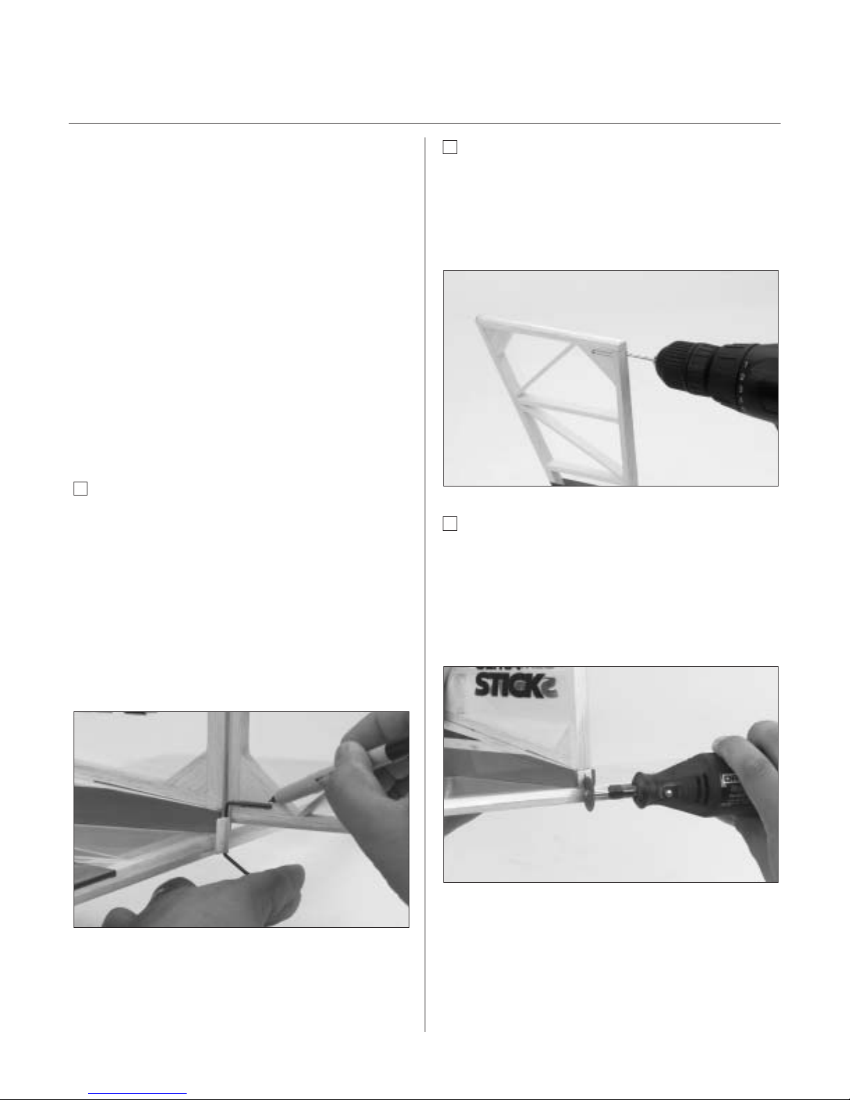
Step 1
On the rear of the fuselage a slot is precut in the wood
structure for the vertical stabilizer. Using a sharp hobby
knife cut away the covering on the top rear of the fuselage
where the vertical stabilizer will insert.
Step 2
Remove the rudder and hinges from the vertical stabilizer
if you have not already done so. The rudder will be
hinged to the vertical stabilizer later.
Step 3
Insert the vertical stabilizer into the slot in the top of the
fuselage and make sure it’s firmly seated against the top
of the fuselage. Check that the rear of the vertical
stabilizer (where the hinge slots are located) is aligned
with the rear of the fuselage.
Step 4
Use a pencil to carefully mark the position of the vertical
stabilizer on both sides where it exits the fuselage. Also
mark onto the fuselage where it contacts. The pencil
should leave a slight indentation in the covering.
Page 23
Section 6: Vertical Stabilizer (Fin) Installation
23
Step 5
Remove the vertical stabilizer. Using a sharp hobby knife
and straightedge, carefully cut away the covering on the
vertical fin and fuselage approximately 1/16" inside the
lines marked in Step 4.
Caution: It’s very important that you do not
press hard enough to cut into the wood
structure, as doing so could weaken the
vertical stabilizer.
Step 6
Mix approximately 1/4 ounce of 30-minute epoxy and
apply it to the vertical stabilizer where it comes into
contact with the fuselage. Also apply epoxy to the
base of the vertical stabilizer where it comes in contact
with the fuselage.
Important: It is essential the vertical
stabilizer base be epoxied to the inside the
fuselage to provide adequate strength. Be
sure to use plenty of epoxy!
Step 7
Insert the fin into the fuselage and wipe away any
excess epoxy using a paper towel and rubbing alcohol.
Step 8
Using a 90-degree triangle, make sure the fin is
perpendicular to the horizontal stabilizer. Use
masking tape to hold the vertical stabilizer in place
until the epoxy cures.
Page 24
24
Section 7: Rudder and Tail Wheel Assembly
Installation
Required Parts
• Fuselage • Rudder
• Hinges • Tail wheel
• Tail wheel collar
• Tail wheel wire assembly
Required Tools and Adhesives
• Drill • Drill Bits: 3/32", 1/16"
• Hobby knife • Felt-tipped pen
• Thin CA glue • Needle-nose pliers
• Paper towels • 30-minute epoxy
• Rubbing alcohol • Mixing stick
• Threadlock Z-42 • Petroleum jelly or oil
• Masking tape • Keyhole saw blade
• CA remover/debonder
• Toothpicks (optional)
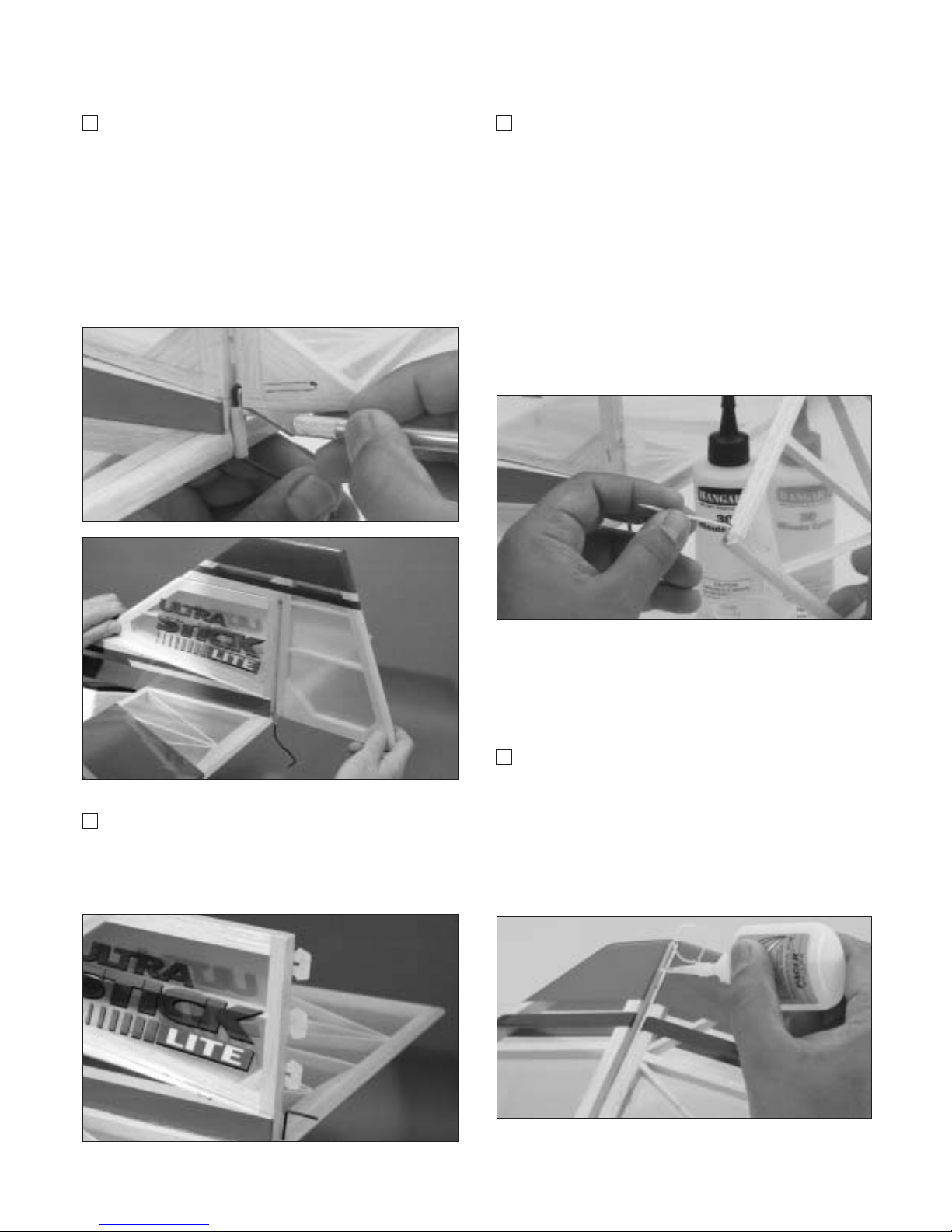
Step 1
Trial fit the rudder on to the vertical fin with the hinges
in place. Locate the tail wheel wire assembly and hold
it up to the fuselage making sure the bottom of the
nylon bushing is flush with the bottom of the horizontal
stabilizer. Note the wire placement in relationship to the
rudder. Using a felt-tipped pen, mark the position where
the hole is to be drilled into the rudder. Also mark the
location for the slot where the bushing tab will be
epoxied into the back of the fuselage. This slot should
be positioned centered on the fuselage tail.
Step 2
Remove the rudder from the vertical fin and use a
3/32” drill bit to drill the hole for the tail wheel wire.
Drill into the exact center of the rudder where you
marked in Step 1. It may be helpful to first drill a
1/16” pilot hole as a guide.
Step 3
Cut a slot and groove in the back of the fuselage where
the tab of the tail wheel bushing will be epoxied. There
are several methods to accomplish this; we used a
Dremel cutting wheel to first cut a slot in the fuselage
as marked in Step 1. Next, use a keyhole saw blade to
enlarge the opening for the tail wheel bushing.
Page 25
Section 7: Rudder and Tail Wheel Assembly Installation
25
Step 4
Trial fit the rudder and tail wheel assembly to the vertical
fin. Note that the rudder will require trimming to allow
clearance for the tail wheel wire/bushing. Mark the
rudder and using a sharp hobby knife, trim back the
rudder only a small amount and refit the rudder to the
fin. Repeat this process until you achieve a perfect fit
with virtually no gap between the vertical fin and rudder.
Remove the rudder from the vertical fin.
Step 5
Reinstall the hinges in the vertical fin using T-pins to
ensure the hinges are centered. The hinges will be
CA’d in Step 7.
Step 6
Mix approximately 1/2 ounce of 30-minute epoxy and
apply it to both the nylon bushing of the tail wheel
assembly where it goes in the back of the fuselage and
to the hole drilled in the rudder for the wire. A toothpick
applicator may be helpful in getting the epoxy into the
hole. Install the rudder and tail wheel assembly to the
vertical fin and fuselage and remove the T-pins. Make
sure the rudder is positioned properly (up and down).
Wipe away any excess epoxy with alcohol and paper
towels. Allow the epoxy to completely cure before
gluing the hinges in place.
Note: Do not get epoxy on the bushing where
it contacts the rudder. The rudder must move
freely on the bushing.
Step 7
After the epoxy has completely cured, apply thin CA to
the hinges by first deflecting the rudder in one direction,
saturating each hinge, and then repeat the process by
deflecting the rudder in the opposite direction. Wipe
away any excess CA by using a paper towel and CA
remover/debonder. Allow the glue to completely cure.
Page 26
26
Section 7: Rudder and Tail Wheel Assembly Installation
Step 8
Once the CA has cured, check for security of the
rudder by gently trying to pull the rudder from the fin.
Also move the rudder several times left and right to
"work in" the hinges.
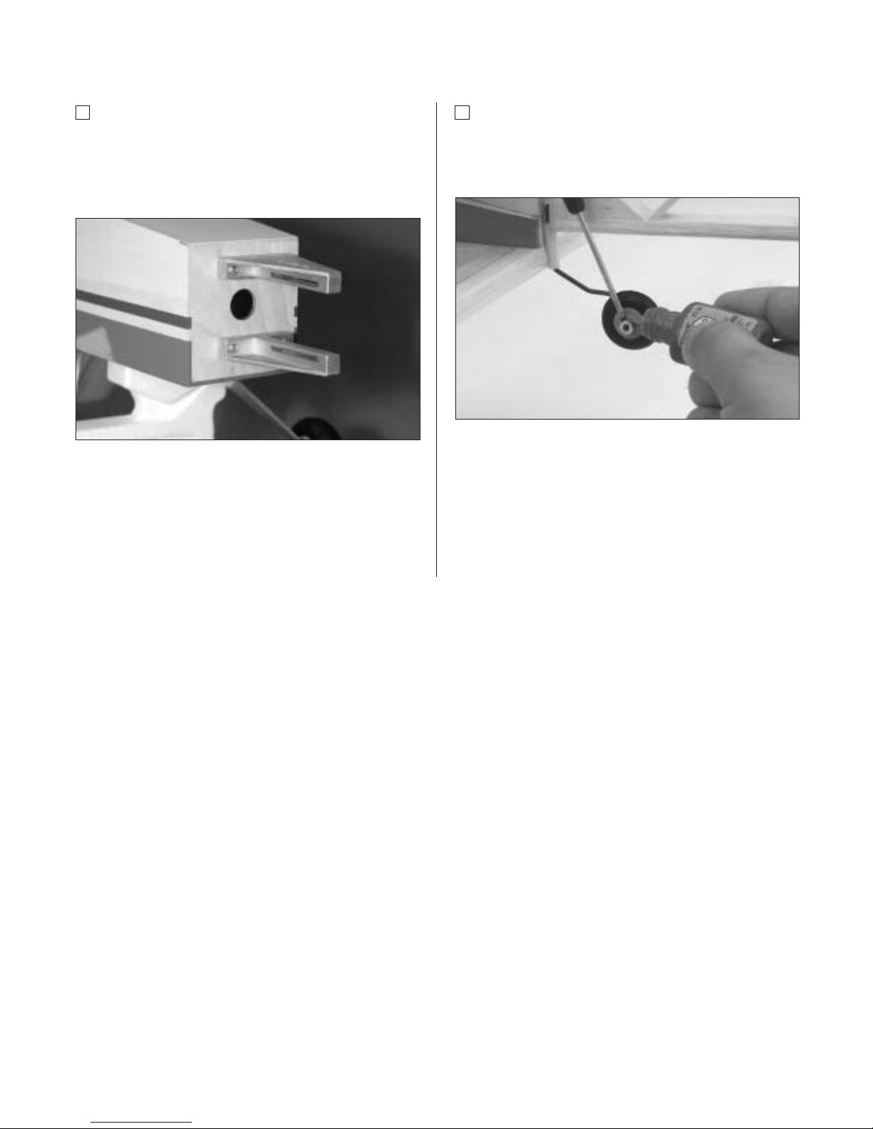
Step 9
Slide the tail wheel onto the tail wheel wire. Next secure
the wheel with the included wheel collar and setscrew.
Use blue Locktite 242 to secure the setscrew in place.
Note: The wheel must rotate freely with only a
small amount of side play. It may be
necessary to drill out the tail wheel slightly so
the wheel can spin freely.
Page 27

Section 8: Hinging the Horizontal Stabilizer and
Elevator
27
Required Parts
• Fuselage • Elevator
• Hinges
Required Tools and Adhesives
• Thin CA glue • CA remover/debonder
• Paper towels • T-pins
Step 1
Locate the elevator and hinges. Trial fit the elevator into
the proper position on the horizontal stabilizer using the
same hinging technique used in Section 1. Remember
to remove the T-pins before applying the CA glue.
Also, make sure the tail wheel is free to move its full
range. You will also need to file a small notch in the
elevator to clear the tail wheel wire.
Important: Do not remove more material
than is necessary. Check to make sure
there is sufficient elevator movement without
any binding.
Step 2
With the elevator aligned (left and right), apply thin CA
glue to the hinges on both sides. Wipe away any excess
CA with CA remover/debonder and a paper towel.
Note: Try to maintain virtually no gap
throughout the length of the elevator-tohorizontal stabilizer hinge line.
Step 3
After the hinges are dry, check to make sure they are
securely in place. Try to pull the elevator from the
horizontal stabilizer. Use care not to crush the structure.
Step 4
Move the elevator up and down several times to
“work-in” the hinges and check for proper movement.
Page 28

28
Section 9: Rudder and Elevator Control Horn
Installation
Required Parts
• Control horns (2) • Fuselage
• Control horn backplates (2)
• Control horn screws (6)
Required Tools and Adhesives
• Drill • Ruler
• Drill Bit: 1/16" • Felt-tipped pen/pencil
• Phillips screwdriver (medium)
Important: When installing the control
horns, make sure the holes in the
control horns, where the pushrod attaches,
are directly in line with the control surface
hinge line.
Step 1
To locate the elevator control horn position, measure over
1" from the fuselage on the top right side of the horizontal
stabilizer. Mark the elevator as shown with a felt-tipped
pen or a pencil. This mark will be the center of the
elevator control horn location.
Step 2
Place the center of the control horn on the elevator at
the mark made in the previous step. Mark the positions
for the control horns with a felt-tipped pen or pencil.
Step 3
Remove the control horn and drill 1/16" holes through
the elevator as marked. Make sure to drill these holes
parallel to each other to allow the back plate of the
horns to fit properly.
Page 29

Section 9: Rudder and Elevator Control Horn Installation
29
Step 4
Using the screws and backplate provided, attach
the elevator control horn and fasten in place with a
Phillips screwdriver.
Step 5
Measure 1"up from the bottom of the rudder on the left
side. Mark the location with a felt-tipped pen or pencil.
This mark will be the center of the rudder control horn.
Step 6
Center the control horn over the mark you’ve just made.
Make sure the horn is positioned over the hinge line, just
like you did for the elevator. Using a felt-tipped pen or
pencil, mark the mounting hole locations onto the rudder.
Step 7
Drill these holes with a 1/16" drill bit and install
the rudder control horn, using the screws and
backplate provided.
Page 30

30
Section 10: Main Landing Gear Installation
Required Parts
• Main landing gear • Fuselage
• Wheels, 2
3
⁄4" (2) • Washers (2)
• Landing gear axles with locknuts (2)
• Wheel collar with screw (2)
• Landing gear bolts (2)
Required Tools and Adhesives
• Hobby knife • Phillips screwdriver
• Moto-tool • Threadlock
Step 1
Attach the axles to the aluminum landing gear, using the
locknuts provided. Slide on the wheel and use the wheel
collar to secure the wheel on the axle.
Note: It is always a good idea to use
Locktite 242 on the wheel collar setscrews
to keep them from coming loose.
Note: You can use a Moto-tool to cut the
extra length off the axle. Be very careful not to
get the axle too hot during the cutting process
or you may melt the wheel hub.
Step 2
Locate the three predrilled mounting holes in the bottom
of the fuselage for mounting the landing gear. The blind
nuts are also preinstalled from inside the fuselage. If the
covering is over the holes, use a sharp hobby knife and
carefully remove the covering over the predrilled holes.
Step 3
Bolt the landing gear onto the fuselage with the included
hardware. Thread the mounting bolts into the preinstalled
blind nuts and securely tighten.
Note: It is a good idea to use Locktite 242 on
the landing gear mounting bolts.
Page 31

Section 11: Fuel Tank Assembly
31
Required Parts
• Metal tubes (2) • Clunk (fuel pickup)
• Fuel pickup tubing • Fuel tank
• Metal caps (2) • Rubber stopper
• 3mm screw
Required Tools and Adhesives
• Hobby knife • Medium Screwdriver
Step 1
Locate the tank parts.
Note: The stopper provided with the
Ultra Stick™ Lite has three holes that are
not completely through the stopper. You will
only be using two holes: one for the fuel
pickup and one for the fuel vent. Make
sure not to open the third hole, as this will
cause a fuel leak.
Step 2
Locate the rubber stopper. Insert the short brass fuel
tube into one of the holes in the stopper so that an
equal amount of tube extends from each side of the
stopper. This tube will be the fuel tank pickup that
provides fuel to the engine.
Step 3
Slide the smaller of the two caps over the tube on the
smaller end of the rubber stopper. The small end will be
inserted into the fuel tank. The larger cap is placed on the
other side of the rubber stopper that makes the cap. Insert
the 3mm screw through the large cap and rubber stopper.
Loosely thread the screw into the small cap as shown.
Page 32

32
Section 11: Fuel Tank Assembly
Step 4
Locate the longer brass fuel tube and bend it as shown
using your fingers. This will be the fuel tank vent tube.
Step 5
Slide the vent tube into one of the two remaining holes
in the stopper from the tank (small cap) side.
Step 6
Locate the short piece of silicone fuel tubing and the fuel
tank clunk. Install the clunk onto one end of the silicone
tubing and the other end onto the brass fuel tank pickup
tube (straight tube) in the stopper.
Step 7
Carefully insert the assembly into the fuel tank. Note
the position of the vent tube. It must be at the top
portion of the fuel tank to function properly. Also, it may
be necessary to shorten the length of the fuel pickup
tubing to make sure the clunk does not rub against
the back of the fuel tank. You should be able to turn the
tank upside down, which allows the clunk to freely drop
to the top of the tank.
Step 8
Tighten the 3mm screw carefully — do not over tighten.
This allows the rubber stopper to form a seal by being
slightly compressed, thus sealing the fuel tank opening.
Important: Be sure to differentiate between the vent and
the fuel pick-up tube. Once the tank is mounted inside the
fuselage, it will be difficult to tell the tubes apart. We have
included two different color pieces of fuel tubing to help
you tell them apart. We suggest using the green tubing
for the fuel line to the carburetor of your engine and the
red tube for the vent tube.
Note: The fuel tank will be installed into the
fuselage after the engine mount is installed.
Page 33

Section 12: Mounting the Engine
33
Required Parts
• Throttle pushrod tube • Fuselage
• Engine • Assembled fuel tank
• Hangar 9™ engine mount w/hardware
• Protective foam (not included)
Required Tools and Adhesives
• 6-minute epoxy • Phillips screwdriver
• Threadlock
Note: When the engine is properly mounted
to the Ultra Stick™ Lite, the distance from the
firewall to the front of the engine drive washer
should be 5
1
⁄4" to 5 1⁄2".
Step 1
Locate the nylon engine mount rails and temporarily
install the mounts using the four engine mount screws
and washers as shown. Note that the engine is mounted
with the cylinder head to the right of the fuselage.
Step 2
Place your engine onto the installed mounting rails and
measure the distance from the firewall to the engine drive
washer (5
1
⁄4" to 5 1⁄2"). Temporarily install the engine to
the rails using four 8-32 bolts, four washers and four lock
nuts. Leave the bolts loose enough to allow the engine to
slide on the engine mount.
Step 3
Locate the throttle pushrod tube included with the kit.
Drill a 1/8" hole in the firewall at the mark you made in
Step 2. Mix a small amount of 6-minute epoxy and glue
the pushrod tube through the firewall leaving
approximately 1/8” protruding through the firewall. Allow
the epoxy to cure before proceeding.
Page 34

34
Section 12: Mounting the Engine
Step 4
Before installing your engine and engine mount, insert the
fuel tank into the fuselage. The two pieces of fuel tubing
should exit through the center hole in the firewall. Use
foam (not included) under and behind the fuel tank and/or
around the fuel tank to secure it in place.
Step 5
Using Locktite Z-42 on the engine mount screws,
install the engine mount to the firewall. Mount the
engine using the supplied hardware (four screws,
washers, and locknuts).
Step 6
Install the fuel pick-up line to the carburetor. The fuel tank
vent line will be installed onto your engine’s muffler.
Page 35

Section 13: Radio System Installation
35
Required Parts
• Fuselage
• Radio packing foam (not included)
• Antenna tube (optional, not included)
• Radio system with 3 servos and hardware (not
included)
Required Tools and Adhesives
• Hobby knife • Drill
• Drill bit: 1/16" • Phillips screwdriver (medium)
Note: Before installing the servos in the servo
tray, we suggest the servo leads be identified
by marking masking tape with the appropriate
letter to designate each servo: T = Throttle,
R = Rudder and E = Elevator).
Step 1
Install the rubber grommets and eyelets in three servos,
per the instructions with your radio equipment. Position
the servos in the fuselage servo tray as shown, noting
that the elevator servo is positioned on the right side of
the fuselage. Mark the location of the servo mounting
screws, remove the servos, and drill pilot holes for the
screws using a 1/16" drill bit. Screw the servos in place
using the 12 servo screws included with the servos.
Hint: To strengthen the servo screw mounting
holes, place a drop of thin CA on each hole
and allow to dry before mounting the servos
to the servo tray.
Step 2
Use radio packing foam (not included, available
at your local hobby shop) when installing the receiver
and battery.
Step 3
Be sure to attach the servo leads to the receiver prior to
installing the receiver into the fuselage (see Radio Set-Up
section). Route the antenna back through the fuselage
using an antenna tube (not included) or route it outside
the fuselage back to the stabilizer. If using an antenna
tube, lightly tape the receiver antenna to the outside of
tube (or route inside of tube) and route the antenna tube
inside the AFT section of the fuselage. Be sure to avoid
the elevator and rudder linkages.
Page 36

36
Section 13: Radio System Installation
Step 4
Wrap the receiver battery in foam and place it in the
fuselage area forward of the servo tray and receiver. We
suggest using layers of foam to hold the battery. Using a
sharp hobby knife, cut a solid layer of foam the size of the
compartment area that is in front of the servo tray. Cut
another layer of foam that is identical in size, however, cut
an opening the center that is the size of the battery pack.
Cut another layer of foam identical in size to the
compartment and place on top of the battery. Cut slits in
the foam to allow the battery lead to exit the foam.
Step 5
The switch should be mounted on the left side of the
fuselage, away from the exhaust of the engine.
Hint: Use the switch plate as a template.
Look inside the fuselage and pick a location
to mount the switch in the opening of the
fuselage side doubler. (Mount only
through the fuselage sheeting, not through
the ply doubler.)
Step 6
Using a 1/16" drill bit, drill two mounting holes for the
switch as marked. Using a hobby knife, carefully cut out
the opening for the switch between the screw holes.
Step 7
Reposition the switch plate as shown and place the
switch on the inside of the fuselage. Using the two screws
supplied with the switch, attach the switch to the fuselage.
Plug in the switch to the receiver/receiver battery.
Page 37

Section 14: Aileron and/or Quad-Flap Linkage
Installation
37
Required Parts
• Wing assembly w/servos installed
• 7
1
⁄2" rods, threaded on one end
(2 for conventional wing, 4 for quad flaps)
• Clevis (2 for conventional aileron, 4 for quad flaps)
• Wire keepers (2 for conventional aileron,
4 for quad flaps)
• Control horn (2 for conventional wing,
4 for quad flaps)
• Control horn mounting screws
• Clevis keepers (2 for conventional wing,
4 for quad flaps)
Required Tools and Adhesives
• Phillips screwdriver • Drill
• Drill Bit: 1/16" • Felt-tipped pen
• Thin CA glue (optional)
Step 1
Locate the short rods threaded on one end, clevis, and
wire keepers. You will also need a control horn, control
horn backplate, and mounting screws to mount the
control horn to the control surface. Instructions will refer
to construction of just one linkage and control horn.
Assembly and installation for both ailerons and/or all four
will follow this same sequence.
Step 2
Before assembly and mounting the linkages/control
horns, it’s a good idea to center the wing servos. Connect
them to the receiver, turn on your transmitter, then the
receiver. Once the servos have moved to their electrical
center, you can position the servo control arm so that it
will be approximately 90 degrees to the linkage when it’s
attached. Adjusting the linkages in or out can do finetuning of the servo arm position. It’s important that the
mechanical adjustments are made as closely as possible
before attempting to make any electrical adjustments
through the transmitter programs.
Important: The aileron/flaps servo arms
should be positioned outboard toward the
wing tips. Failure to do this can cause radio
programming difficulties, resulting in the flaps
or ailerons moving in the wrong direction.
Note: If you are using a Y-harness to
connect servos to a receiver and if you are
setting up a quad-flap configuration, refer to
the “Radio Set-Up” section of this manual
for further instruction on position of the
servo control arms.
Page 38

38
Section 14: Aileron and/or Quad-Flap Linkage Installation
Step 3
The control horn should be positioned so the holes
the clevis connects into are over the hinge line of the
control surface.
Step 4
Once satisfied with the horn location, (it should be a
straight line from the servo arm to the horn), mark
the location with a felt-tipped pen.
Step 5
Using a 1/16" drill bit, drill the screw holes for mounting
the control horn. Use caution to drill straight through at a
90-degree angle to the control surface.
Step 6
Attach the control horn to the aileron (flap) using the
screws and the control horn backplate. Be careful not to
accidentally puncture the covering with the screwdriver.
Step 7
Thread a 2-56 clevis on the threaded end of the control
rod. Screw the clevis on a minimum of 7-10 turns. Install
the clevis with wire on the control horn into the third hole
from the mounting base. Be sure to install the clevis
keeper (fuel tubing) over the clevis.
Page 39

Section 14: Aileron and/or Quad-Flap Linkage Installation
39
Step 8
With the linkage attached to the control horn, center the
control surface and hold the linkage wire directly over the
electronically centered servo arm. Place a mark on the rod
directly over the hole (second hole from the end of arm)
in the servo control arm that it will connect to.
Step 9
Remove the clevis from the control horn. Make a
90-degree bend in the rod at the marked location
and cut off the excess rod, leaving 5/16" of rod past the
90-degree bend.
Step 10
Attach a wire keeper to the end of the rod with the
90-degree bend. Insert the 90-degree bend through the
second hole from the end of the servo arm and install the
end of the wire keeper over the end of the wire. Install the
clevis back onto the control horn. Be sure to slide the
silicon clevis keeper on the end of the clevis.
Step 11
Repeat the process for the remainder of the
aileron/flaps linkages.
Page 40

40
Section 15: Rudder, Elevator and Throttle Pushrod
Installation
Required Parts
• Control horn (2) • Fuselage
• Wire keeper (2) • Clevis (2)
• Easy connector • Clevis keeper (2)
• 19
1
⁄2" pushrod wire, 1.5mm
• 30" pushrod wire, 2-56 threaded on one end (2)
Required Tools and Adhesives
• Felt-tipped pen/pencil • Hobby knife
• Needle-nose/Z-bend pliers
Step 1
Locate one of the long 30" pushrod wires threaded on one
end, a 2-56 clevis, wire keeper, and a clevis keeper. The
rudder and elevator pushrods are made using these parts
shown below. The throttle linkage will be made from the
shorter 19
1
⁄2" rod.
Step 2
Note that the pushrod wire guide tubes are preinstalled in
the fuselage. On the aft end of the fuselage find the
pushrod exits for the rudder and elevator pushrod. Using
your hobby knife, carefully cut away the covering over the
pushrod exit on the top left side of the fuselage next to
the vertical stabilizer and the opening on the right side of
the fuselage where the elevator pushrod will exit. Be
careful not to cut the pushrod guide tube.
Step 3
Insert one of the 30" pushrod wires through the guide
tube with the threads exiting the tube at the aft end of the
fuselage. Screw on a clevis 7–10 turns and snap it onto
the control horn.
Page 41

Section 15: Rudder, Elevator and Throttle Pushrod Installation
41
Step 4
With the clevis attached to the control horn, center the
control surface and hold the pushrod wire directly over
the electronically centered servo arm. Place a mark on the
rod directly over the hole (second hole from the end of
arm) in the servo control arm it will connect to.
Step 5
Remove the clevis and slide the pushrod wire out of the
guide tube. Make a 90-degree bend in the rod at the
location you just marked and cut off the rod leaving 5/16”
extending out from the 90-degree bend.
Step 6
Attach a wire keeper to the end of the rod with the
90-degree bend you just made. Insert the threaded
end of the pushrod wire through the wire guide tube
from the wing saddle opening of the fuselage. Install the
90-degree bend through the second hole from the end
of the servo arm and install the end of the wire keeper
over the end of the wire.
Step 7
Install the clevis back onto the pushrod wire and connect
it to the control horn. Be sure to slide the silicone clevis
keeper onto the end of the clevis before attaching the
clevis to the control horn. After the clevis is attached to
the control horn, slide the clevis keeper onto the end of
the clevis to insure it will not prematurely open.
Step 8
Repeat the process for either the rudder or elevator,
whichever one you have not done.
Installing the Throttle Pushrod
The sequence to install the throttle pushrod in this
manual is for most four-stroke engines. Installation may
vary depending on the type/brand of engine you use to
power your Ultra Stick™ Lite.
Page 42

42
Section 15: Rudder, Elevator and Throttle Pushrod Installation
Step 9
Locate the smaller 1.5mm, 19
1
⁄2" pushrod and thread
a clevis onto the threaded end. Insert the rod into the
throttle pushrod tube previously installed.
Step 10
Install the easy connector to the throttle servo arm by
inserting the bottom post through the second hole from
the end in the throttle arm. Install the snap washer on
the easy connector stem, securing it to the arm.
Step 11
Connect the clevis end of the pushrod to the throttle arm.
Step 12
Turn on your radio system and center your transmitter’s
throttle stick and trim and center your throttle servo
arm. Put the throttle arm of your engine to the
1/2 open/closed position.
Step 13
With your radio system on, the throttle controls centered,
and throttle arm in the 1/2 open/closed position, secure
the throttle pushrod wire to the easy connector by
tightening the screw in the top of the connector to the
pushrod wire. Trim off the excess wire.
Page 43

Section 16: Control Throw Recommendations
43
The following control throw recommendations offer
positive response and are a good place to begin setting
up the aircraft. After you have become more familiar with
the flight characteristics of the Ultra Stick™ Lite, adjust
the control throws to meet your flying style.
Low Rate High Rate
Aileron 3/4" up 1 1⁄4" up
3/4" down 1
1
⁄4" down
* Both wing types
Elevator 1" up 1 1⁄2" up
1" down 1
1
⁄2" down
Rudder 2 1⁄2" right 4" right
2 1⁄2" left 4" left
Flaps 1 1⁄2" down
Section 17: Balancing the Ultra Stick Lite
An important part of preparing the aircraft for flight is
properly balancing the model. This is especially important
when various engines are mounted.
Caution: Do not inadvertently skip this step!!
The recommended Center of Gravity (C.G.) location for
the Ultra Stick™ Lite is 4 1⁄8" behind the leading edge of
the wing. If necessary, move the battery pack or add
weight to either the nose or the tail until the correct
balance is achieved. Stick-on weights are available at
your local hobby shop and work well for this purpose.
Page 44

44
Section 18: Quad Flaps
The quad-flap option allows your Ultra Stick™ Lite to
perform in ways that are just not possible with the
conventional ailerons-only setup. With the quad flaps and
a computer radio, different wing configurations can be
programmed to extend the flight performance envelope.
It’s also a great way to learn more about your computer
radio. Some of these configurations include the following:
Crow
What is Crow?
Ailerons up, flaps down, elevator down
What does Crow do?
Crow is a very high drag configuration that is commonly
used as dive brakes to prevent the airplane from building
up speed during steep descents/dives. Crow is great for
bleeding off excess airspeed and/or altitude, making short
landings from high altitudes possible. With a little
practice, it’s easy to shoot landings in front of yourself
from 500 feet or more of altitude and just 100 feet
downwind from where you’re standing. Just deploy Crow,
push the nose straight down, and then pull elevator to
level at about 10 feet and land right in front of yourself at
a slow walking speed. The drag caused from Crow will
prevent the Ultra Stick Lite from gaining speed on the
down line and, when the airplane is pulled to level, it will
slow to a crawl within a short distance.
Another favorite maneuver that Crow allows is to fly nose
high at very slow speeds with a high angle of attack
(nearly 45°). Use full-up elevator and jockey the throttle
position to maintain level flight. This maneuver is
sometimes called a Harrier. With Crow activated, the Ultra
Stick Lite has reduced tendency to tip stall. This is
because the up ailerons at the tips of the wings (washout)
help to keep the wing tips from stalling. Use the rudder
only to steer the Ultra Stick Lite during this maneuver. If
you turn off the Crow at these slow, high-angle-of-attack
speeds, as there may not be enough airspeed to fly in the
conventional mode. Anytime Crow is activated, the nose
pitches up slightly, so it’s recommended to mix some
down elevator (about 1/4") whenever Crow is used.
First Flight Profile with Crow
On the first test flights, deploy the Crow at fairly high
altitudes at various throttle settings to get a feel for the
effects of Crow. You’ll likely notice some reduction in roll
control (ailerons) and the extra drag will drastically slow
the airplane, no matter what throttle position or maneuver
you’re doing. Check to see if the nose pitches up or down
and adjust the elevator-mixing value after landing if
necessary. Tr y some steep descents with Crow and notice
that the Ultra Stick Lite builds up very little speed on the
way down. Shoot some landings with Crow activated.
You’ll likely come up way short on your first few full Crow
landings, so don’t be surprised if you’ve got to add
throttle. With a little practice, you’ll confidently be able to
do full-up elevator, tail-first landings.
On your first attempts to do the Harrier, start high. Deploy
Crow and throttle back to idle; then, start adding up
elevator smoothly. As full-up elevator is reached, increase
the throttle, just enough to maintain altitude. You can fly
around in the nose-high attitude using rudder only to
steer and, with some practice, you’ll be doing Harrier
landings with ease.
Dive Brakes to Landing
Crow
Page 45

Section 18: Quad Flaps
45
What to Watch For
In Crow, the wing tips are effectively washed out because
the up ailerons reduce the tendency to tip stall, making
for very stable slow flight when the airplane is upright.
When inverted or doing outside maneuvers, this washout
effectively becomes wash-in (ailerons are down) and a tip
stall can occur. Be careful when flying inverted or doing
outside maneuvers with Crow deployed, as an unexpected
tip stall could occur. Also, when doing high angle-ofattack flight or the Harrier at very slow speeds, it’s
recommended that you keep the Crow turned on.
Crow allows the Ultra Stick™ Lite to actually fly slower
and at higher angles of attack than in the
conventional configuration.
Elevator-to-Flaps
An up-elevator command causes the flaps to go
down, while a down-elevator command causes
the flaps to go up.
What does elevator-to-flap do?
Elevator-to-flap mixing causes more aggressive
pitching when elevator is applied, making for tighter
inside and outside loops. Using the recommended
throws, the Ultra Stick Lite is capable of very tight
15-foot diameter loops.
First Flight Profile
It’s a good idea to start up high, then turn on the
elevator-to-flap mixing to get accustomed to the
increased pitch (elevator) sensitivity. You may find it
necessary to increase the elevator expo to tame the
aggressiveness around center. Now try some full up
loops first with the mixing on and then off to see just how
effective elevator-to-flaps can be. With practice, you can
bring these tight loops right down to the deck and even
do tight head-high outside loops.
Things to Watch For
The only real place you may run into trouble here is
getting used to the increased pitch sensitivity and thus
over-control the airplane. Just take it easy, staying at least
two mistakes high until you’re comfortable with the way
the Ultra Stick Lite responds.
Later you may want to try differing amounts of flap travel
with elevator to see the effects.
Aileron-to-Flaps
An aileron input causes the flaps to operate in the same
direction as ailerons (i.e. a right aileron input causes the
right aileron and right flap to go up and the left aileron
and left flap to go down).
What does it do?
Aileron-to-flap mixing gives a more aggressive roll
rate for doing rapid rolls. This mix also increases the
rotation rate of snaps, spins or any other maneuver
that uses ailerons.
Tight Loops
Couple elevator to flaps
Rapid Rolls
Couple ailerons to flaps
Page 46

46
Section 18: Quad Flaps
First Flight Profile
Start high and turn on the aileron-to-flap mix. Now do a
couple of full-deflection, high-rate rolls and note the
difference in roll rate. You should see about a 30%
increase in roll speed. Now try a couple of snaps (full up,
full right aileron and full right rudder). You’ll find snaps
and spins tighter, faster and more aggressive.
What to Watch For
Be careful not to over-control the ailerons on your
first attempts.
Short Takeoff Flaps
The flaps are set to a down position.
What does it do?
Short takeoff flaps create a high-lift wing that allows
the Ultra Stick™ Lite to do very short takeoffs, in some
instances (from asphalt with a powerful engine) within
the length of the fuselage.
First Flight Profile
After you have become comfortable with the flight
characteristics of your Ultra Stick Lite, it’s time to give the
short takeoff flaps a try. On the runway drop the flaps,
then punch the throttle and hold some up elevator. Be
ready for the Ultra Stick Lite to break ground and head for
the skies! It’s important to release up elevator when the
airplane breaks ground, then turn off the flaps to resume
flights. On later flights, try holding full up elevator to
shorten the roll out even more.
What to Watch For
On your first flap takeoffs, you may be surprised at just
how quickly the Ultra Stick Lite pops off the ground,
especially with a strong engine. Be ready to release any
up elevator quickly. Also, you’ll notice that the flap causes
the nose to pitch up a bit. We normally don’t recommend
mixing in elevator compensation (a bit of down elevator),
as the intention of short takeoff flaps is to get off the
ground in as short a distance as possible. Just turn off
the flap shortly after takeoff.
Short Takeoff
Full flaps
Page 47

Programming Guide — JR XP652/642
Section 19: Radio Programming Guide
47
Following is a programming guide that provides step-bystep illustrations on how to program quad-flap
configurations for JR’s XP652/642, XP783/347/388S,
XP8103, and 10X/10SxII/10Sx radios, as well as for
Futaba’s 8-channel 8UA/S radio.
Once you understand your computer radio, you’ll soon
discover that there are many other possible programming
configurations (e.g., right rudder causes the right aileron
to go up and the right flap to go down, causing a severe
right yaw). We challenge you to try as many possibilities
as you can think of — just remember, start high!
If you come up with any interesting ideas, we’d like to
hear from you.
Note: If you have a computer radio that’s not listed,
please consult the instructions included with that
radio or contact the radio’s manufacturer for
programming information.
JR XP652 or XP642 pages 47–52
JR XP783 or XP347 or XP388S pages 53–60
JR XP8103 pages 61–68
JR 10X, 10SxII, 10Sx pages 69–72
Futaba 8UA/S pages 73–78
Programming Your JR™ XP652/642 in
10 Easy Steps
JR’s XP652 and XP642 feature the same base
level of programming, so the procedure for
setting up quad flaps for each radio is identical.
Note: Because these are 6-channel radios,
it’s necessary to use one reversed servo and
a Y-harness to connect the flap servos in
the wing. This allows the Crow, takeoff
flaps, and elevator-to-flap configurations to
be used. However, the aileron-to-flap
configuration is only available with
7-channel or more computer radios.
First, it’s important to plug each servo into the
correct port in the receiver.
Note: When setting up a new aircraft,
it’s important to reset the programming
to the factory defaults.
ON
OFF
AUXILIARY 1 (FLAP)
GEAR
RUDDER
ELEVATOR
AILERON
THROTTLE
ON/OFF SWITCH HARNESS
(JRPA003)
RECEIVER BATTERY
4N-600
226X RECEIVER
NEW ABC & W SYSTEM
6 CHANNEL RECEIVER
BATT
AUX 1
GEAR
RUDD
ELEV
AILE
THRO
NER-226X
JAPAN REMOTE CONTROL CO., LTD
MADE IN JAPAN
72MHz
ANTENNA
R600 RECEIVER
LEFT
AILERON
THROTTLE
RUDDER
ELEVATOR
(STANDARD)
RIGHT FLAP
(REVERSE)
LEFT FLAP
RIGHT
AILERON
Y-HARNESS
Note: One flap servo
must be reversed.
6 CH 72MHz FM RECEIVER
ABC&W INTERFERENCE
PROTECTION SYSTEM
BATT
AUX 1
GEAR
RUDD
ELEV
AILE
THRO
ELEVATOR
AILERON
Page 48

48
Programming Guide — JR™ XP652/642
Step 1. Resetting the programming to factory defaults:
Hold down both the Mode and Channel keys and turn on the radio to
enter System Setup mode. Now press the Mode key until “RST”
appears on your screen. Now press the Increase
and Decrease keys simultaneously to reset the programming to
factory defaults.
MODE
ENTER
CHANNEL
Press the mode button to
access the mix wing screen.
Press the INCREASE
button to activate
Flaperon mixing.
OF
MIX WING
INCREASE
CLEAR
+–
DECREASE
OF = MIX OFF
ON = MIX ON
THR : THROTTLE
AIL : AILERON LEFT
ELE : ELEVATOR
RUD: RUDDER
GER : FLAPS
FLP : AILERON RIGHT
Step 2. Setting wing type to flaperons: In System Setup mode,
press the Mode key until the “MIX WING” screen appears. (See above)
Now press the Increase key until “FPR ON” appears on the screen.
Step 3. Set reversing switches: Turn the transmitter off then
back on again. Now press the Mode and Channel key simultaneously
to access the Function mode. Now press the Mode key to access the
“REV-Norm” screen. Press the Channel key to access each channel,
then check that the selected channel is moving in the correct direction
(e.g., a right aileron command causes the right aileron to go up and
the left aileron to go down). To change the servo direction, press the
Increase key. Check all channels and adjust as necessary.
Note: With the gear channel pulled toward you, the flaps should
go down. With the flap switch pulled toward you, both ailerons
should go up.
RST
AC
ENTER
MODE
Press the MODE button
until "RST" appears on
the screen.
CHANNEL INCREASE
INDICATES DATA RESET FUNCTION
MODEL TYPE TO RESET
CLEAR
+
Press the INCREASE and
DECREASE buttons simultaneously
to reset the data (a beep will sound).
—
DECREASE
THR
◆
REV NORM
ENTER
MODE
Press the MODE
button until
◆
"REV NORM"
appears on
the screen.
CHANNEL INCREASE
Press the
CHANNEL button
until the desired
channel appears
on the screen.
CHANNEL
1 THR: THROTTLE
2 AIL: AILERON
3 ELE: ELEVATOR
4 RUD: RUDDER
5 GER: LANDING GEAR
6 FLP: FLAP (AC ONLY)
CLEAR
+
Press the INCREASE or DECREASE
button to change the servo direction.
—
DECREASE
Page 49

Programming Guide — JR™ XP652/642
49
INDICATES THE
Step 4. Sub-trim: With the flap and gear switches in the rearward
position and the mechanical trims centered, reposition any of the
servo arms if necessary such that all control surfaces are at neutral or
as close to neutral as possible. Now press the Mode key to access the
SB-TRM function. The Channel key allows you to select the desired
channel, while the Increase and Decrease keys change the center
position. Adjust the sub-trim as necessary until all control
surfaces are neutral.
Step 5. Set travel adjust: Press the Mode key until
“TRV ADJ.” appears on your screen. Pressing the CH key will allow
access to each channel. Adjust the travel of each channel to the
following using the Increase or Decrease keys.
Important: Move the flap switch to the rearward position. Adjust
the FL. Travel adjust to 0%. Reposition the servo arm so that the
ailerons are neutral. If necessary, readjust the aileron sub trims
slightly.
Note: To get the most performance out of your Ultra Stick™ Lite,
long servo arms (1 inch) like JRPA215 are
recommended. This provides for large control throws, allowing
for more aggressive maneuvers. To achieve the control throws
listed below, long servo arms may be necessary.
Note: Use the Dual Rate function to achieve these throws (see
page 52).
Throttle — Full throttle to full closed
Aileron — 1
1
⁄4" up, 11⁄4" down
Elevator— 11⁄2" up, 11⁄2" down
Rudder — 4" right, 4" left (rudder throws measured
at bottom)
Flaps — 11⁄2down when the gear switch is pulled for-ward
(adjust with GEAR channel travel adj.)
SUB-TRIM FUNCTION
SB-TRIM
THR
CHANNEL
1 THR: THROTTLE
2 AIL: AILERON
3 ELE: ELEVATOR
4 RUD: RUDDER
5 GER: LANDING GEAR
6 FLP: FLAP (AC ONLY)
0
ENTER
MODE
Press the
MODE button
until "SB-TRIM"
appears on
the screen.
CHANNEL INCREASE
Press the
CHANNEL button
until the desired
channel appears
on the screen.
INDICATES THE TRAVEL
ADJUSTMENT FUNCTION
TRV ADJ.
THR
%
+100
SUB-TRIM VALUE ( 125)
+
Press the INCREASE or DECREASE
button to adjust the sub-trim value.
±
CLEAR
—
DECREASE
CHANNEL
1 THR: THROTTLE
2 AIL: AILERON
3 ELE: ELEVATOR
4 RUD: RUDDER
5 GER: LANDING GEAR
6 FLP: FLAP (AC ONLY)
TRAVEL ADJUSTMENT VALUE
SERVO OPERATING DIRECTION
ENTER
MODE
Press the
MODE button
until "TRV ADJ."
appears on
the screen.
CHANNEL INCREASE
Press the
CHANNEL button
until the desired
channel appears
on the screen.
CLEAR
+
Press the INCREASE or DECREASE
button to adjust the travel adjustment value.
—
DECREASE
Page 50

50
Programming Guide — JR™ XP652/642
Note: The dual-rate switch position
is changed/accessed by setting the
appropriate dual-rate switch to the 0
or 1 positions.
Step 6. Adjusting the dual rates: Press the Mode key until the
dual-rate screen appears. The Channel key allows you to select the
aileron or elevator channel while the respective dual-rate switch
allows you to select position 0 or 1. Adjust the high rate to 100% and
the low rate to 50% using the Increase and Decrease keys. First flights
should be attempted on low rates.
MODE
ENTER
CHANNEL
SWITCH POSITION
AI = AILERON
EL = ELEVATOR
EXPONENTIAL VALUE
0
%
AIO
Press the (+) and (-) buttons to
increase/decrease the
exponential valve (0–100%).
Press the MODE
button until “EXP”
appears on the
left side of the
screen.
Note: The exponential switch position is
changed/accessed by setting the appropriate
dual-rate switch to the 0 or 1 positions.
Press the CHANNEL
button to select either
aileron or elevator
exponential.
INCREASE
CLEAR
EXP
+–
DECREASE
Step 7. Using exponential: Exponential is used to reduce the
sensitivity of control around center while still providing
full control authority when the control stick is fully deflected.
Because the Ultra Stick™ Lite uses large control throws, it’s a good
idea to give Expo a try, even if you’ve never used it before, to help
prevent over-controlling. Press the Modekey until “EXP” appears
on your screen. Use the Channel key to select the aileron or elevator
channel, then use the exponential switch to access position 0 or 1.
Separate expo values can be programmed for position 0 and 1.
Press the Increase or Decrease keys to program the desired expo
value for the selected channel and switch position. We recommend
starting with an expo value of 25% on elevator and 30% on
ailerons. Then, on subsequent flights, adjust the value until the
desired control feel is achieved.
INDICATES THE DUAL-RATE FUNCTION
CHANNEL
AI : AILERON
EL : ELEVATOR
D/R
AIO
%
I00
ENTER
MODE
Press the MODE
button until "D/R"
appears on the
screen.
CHANNEL INCREASE
Press the
CHANNEL button
until "AI" or "EL"
appears on the
screen.
SWITCH POSITION (0 OR 1)
DUAL-RATE VALUE (0—125%)
CLEAR
+
Press the INCREASE or DECREASE
button to adjust the dual rate value.
—
DECREASE
Page 51

Programming Guide — JR™ XP652/642
51
MODE
ENTER
35
%
A35
CURRENT MIX
CURRENT MIX
CHANNELS
INCREASE
CLEAR
MIX
+–
DECREASE
Press the MODE button
until “MIXA11” appears
on the screen.
Step 8. Mixing elevator-to-flaps: Press the Modekey until the
“MIX A11” screen appears. This is programmable MIX A and it allows
you to mix any channel to any other channel or even to itself. Press the
Channel key until the “MIX Ach” appears. This screen will allow you to
select the master (elevator) and slave (in this case GEAR because GEAR
is being used to deploy flaps). Elevator is channel 3, so press the
Increase key until the screen reads “31.” The first digit (3) is now the
master channel (elevator). Now press the Decrease key until “35”
appears in the screen. The second digit (5) is now the slave channel
(gear, which we have Y-harnessed to flaps). This gives us an elevatorto-flap mix. Press the Channel key twice until “0%” appears on the
screen. Now hold up elevator and press the Increase key until 35% is
achieved. An up elevator command should result in the flap going
down. If the flaps go up instead, this 35% value needs to be -35%.
Press the Decrease key until -35% is achieved. Now holding
down elevator, press the Increase or Decrease key so that the flap
goes up 35%.
Note: It’s possible to assign this mix to be turned off/on using a
selected switch. Press the Channel key until “MIX-ASW” appears.
Pressing the Increase key will allow you to assign this mix:
F1 = flap switch
A = aileron dual-rate switch
E = elevator dual-rate switch
ON = always on
ENTER
27
%
B65
CURRENT MIX
CURRENT MIX
CHANNELS
INCREASE
CLEAR
MIX
+–
DECREASE
Step 9. Crow mixing: We’ve already done 1/3 of the work in crow
mixing above when we activated the flaperons and adjusted the
ailerons to go up when the flap switch is pulled in Steps 2 and 5. Now
we need to add down flaps and some down elevator. To get down flap
when the flap switch is pulled, we’re going to mix flap as master to
gear as slave. Press the Mode key until “MIXB11” appears on the
screen. Now press the Channel key to access the “MIXBch” screen.
Press the Increase key until “61” appears, then press the Decrease key
until “65” appears in the screen. This programs channel 6 (flaps) as
master and channel 5 (gear) as slave. Now press the Channel key until
“MIX65 0%” appears on the screen. With the flap switch pulled
forward, press the Increase key or Decrease key until the flaps
go down 11⁄2".
CHANNEL
CHANNELMODE
Step 10. Elevator Offset: To set the necessary down elevator with
Crow, press the Modekey until “OFFSET F-E” appears on the screen.
With the flap switch in the forward position, press the Increase or
Decrease key until the elevator goes down 5/8."
F-E
OFFSET
0
ENTER
MODE
CHANNEL INCREASE
INDICATES FLAP-TO-ELEVATOR
OFFSET TRIM FUNCTION
ELEVATOR OFFSET VALUE ( 125)
CLEAR
+
±
—
DECREASE
Press the MODE button
until "OFFSET F-E" appears
on the screen.
Press the INCREASE or DECREASE
button to adjust the flap elevator
offset value.
Page 52

52
Programming Guide — JR™ XP652/642
Elevator-To-Flap
Mix can be
assigned to one
of these switches
or always left on.
Crow Switch
Takeoff Flap Switch
Note: The takeoff flaps should be retracted before using the Crow function to prevent any over-travel of the flap servos.
Page 53

Programming Guide — JR™ XP783/XP347/XP388S
53
JR’s XP783, XP347 and XP388S all feature the same base level
programming, so the procedure for setting up quad flaps for each
radio is identical.
Note: Most of the quad-flap features needed for the Ultra Stick™ Lite
are already preprogrammed in the glider (referred to as GLID) software
included in these three radios. While the Ultra Stick
™
Lite is not a
glider, there are several built-in features in
the glider programming that make quad-flap easier to program and
use. We strongly suggest using the GLID model type programming
that’s included in these radios.
Programming the JR XP783, XP347 and XP388S in 15 Easy Steps
Receiver Battery
4N600
4.8V 600mAh
JAPAN REMOTE CONTROL CO., LTD.
¤
ON
OFF
Not Used
Auxiliary 2/Flap (left)
Auxiliary 1/Flap (right)
Aileron (left)
Rudder
Elevator
Aileron (right)
Throttle
Pulse Code Modulation
BATT
AUX 4
AUX 3
AUX 2
AUX 1
GEAR
RUDD
ELEV
AILE
THRO
9 CHANNEL RECEIVER
NER-649S
NEW ABC & W SYSTEM
JAPAN REMOTE CONTROL CO. LTD
MADE IN JAPAN
72 MHZ
Not Used
NER-649S
S-PCM Receiver
JRPR649
When setting up a new aircraft, it’s important to reset the
programming to the factory defaults.
MDL.1
RSET
Model No. to be Reset
Function Being Programmed
Data Reset Key
+
CLR
–
UP CHDN
Step 1. Resetting the programming to factory defaults: Hold
down both the Up and the Down keys simultaneously and turn on the
radio to enter System Setup mode. Now press the Up key until “RSET”
(reset) appears on the screen. Pressing the CLR key will reset the
programming to the factory defaults.
Page 54

54
Programming Guide — JR™ XP783/XP347/XP388S
Select Aircraft Type
+
CLR
–
UP CHDN
TYPE
GLID
Function Being
Programmed
Select Aircraft Type
HELI: Helicopter
ACRO: Airplane
GLID: Glider
Step 2. Selecting model type (GLID): In System Setup mode,
press the Up key until the “TYPE” screen appears.
Now press the (+) key until “GLID” appears on the screen.
V–TL
INH
MIX
Wing Type Display
V-TL: V-Tail
DUA-F: Dual Flap
Setting Condition
INH: Inhibit
ACT: Active (Mixing ON)
Reverse Current Setting
(INH - ACT)
Current Setting OFF (INH)
+
CLR
–
Wing Mixing
Display Change
UP
CHDN
Step 3. Activating dual flap: In System Setup mode, press the Up
key until the “V-TL INH” screen is displayed. Press the CH key to
access the mix “DUA.F” screen. Press the (+) key to activate (ACT) the
dual-flap function.
Flap Channel Input Selection
(pot. 6 - SW+T)
Reset to POT. 6
+
CLR
–
UP CHDN
FLAP
POT.6
Function Being Programmed
Current Flap Channel Input
POT.6: Flap Knob
SW+T: Flap Switch and Pot.6
Step 4. Assigning the flaps to the flap switch: In System Setup
mode, press the Up key until “FLAP POT.6” appears on the screen.
Press the (+) key so that “SW+T” appears.
Note: With the JR X347 the flaps are automatically assigned to
the switch. This step should be ignored.
Page 55

Programming Guide — JR™ XP783/XP347/XP388S
55
RUDD
NORM
REVERSE SW
Function Being Programmed
THRO: Throttle
AILE: Aileron
ELEV: Elevator
RUDD: Rudder
GEAR: Gear (Left Aileron - Aileron 1)
AUX1: Auxiliary 1
(Right Flap Channel for Dual Flaps)
AUX2: Auxiliary 2
(Left Flap Channel for Dual Flaps)
Channel Display
Setting Condition
NORM: Normal
REV: Reverse
Travel Direction Selection Resets Travel Direction
to Normal
+
CLR
–
Channel Selection
UP
CHDN
Step 5. Setting servo reversing: Turn the transmitter off, then back
on again. Press the Up and Down keys simultaneously to access the
Function mode. Press the Up key until the “REV” function appears on
the screen. Press the Channel key to select each channel and check
that the servo direction is operating correctly for each channel. To
change the direction of the selected channel, press the (+) or (-) key.
Check and adjust all channels as necessary.
Note: When the three-position flap switch is pulled down, the
flap should come down. If they go up, reverse the direction of
channel 6 (AUX 1) and/or 7 (AUX 2).
Note: Because the GLID model programming is being used,
the transmitter refers to the throttle function as SPOI or spoilers.
Any time “SPOI” is displayed, it functions as throttle.
POT.S
TRIM
Setting Operation
TRIM: Trim Operation
INH: Inhibited
Trim Display
POT.5: Flap Trim of Flaperon
POT.6: Dual Flap’s Flaptrim
(Only if Dual Flap is Active)
POT.7 Dual Flap’s Aileron Trim
(Only if Dual Flap is Active)
Reverse Current Function
Setting Operation
Function Reset to Trim
+
CLR
–
Trim Display
Selection
UP
CH
DN
Step 6. Turning off the trim knobs: In Function mode, press the
Up key until the “POT.5 TRIM” screen appears. Pressing the CHkey
will advance through the three available trim pots: 5, 6, and 7. Inhibit
all three by pressing the (+) key when each one is selected. This will
prevent any unwanted control movement should the knobs be moved.
Note: With the 347, POT.6 is not available.
Page 56

56
Programming Guide — JR™ XP783/XP347/XP388S
AILE
0
S.TRIM
Function Being Programmed
Indicates Channel for Which
Sub-Trim is Being Adjusted
Sub-Trim Value for Indicated Channel
(Range –125)
THRO: Throttle (Spoiler)
AILE: Aileron (Right Aileron)
ELEV: Elevator
RUDD: Rudder
GEAR: Gear (Left Aileron – Aileron 1)
AUX1: Auxiliary 1
(Right Flap Channel for Dual Flaps)
AUX2: Auxiliary 2
(Left Flap Channel for Dual Flaps)
Increases
Sub-Trim Value
Decreases
Sub-Trim Value
Resets Sub-Trim
Value to 0%
+
CLR
–
Channel Selection
UP
CHDN
Step 7. Adjusting the sub trims: Turn on the transmitter and
receiver and center the trims. Move the flap switch in the upper
position. Now reposition all the servo arms so that all the control
surfaces are as close as possible to their neutral positions.
In System Setup mode, press the Up key until the “S.TRIM” screen
appears. Now press the Channel key to access the desired channel and
press the (+) or (-) key to perfectly center each control surface.
AILE
R 100
%
T.ADJ
Function Being Programmed
Indicates Channel for Which
Travel Adjust is Being Programmed
Servo Acting Direction Travel Value Adjust
(0–150%)
THRO: Throttle (Spoiler)
AILE: Aileron (Right Aileron)
ELEV: Elevator
RUDD: Rudder
GEAR: Gear (Left Aileron – Aileron 1)
AUX1: Auxiliary 1
(Right Flap Channel for Dual Flaps)
AUX2: Auxiliary 2
(Left Flap Channel for Dual Flaps)
Increase or Decrease
Travel Value
Resets Travel Adjust
to 100%
+
CLR
–
Channel SelectionTo Elevator-to-
Flap Mixing
To Sub-Trim
UP
CHDN
Note: The throttle is referred to as “SPOI” in the glider mode.
Step 8. Setting Travel Adjust: Press the Up key until the “T.ADJ”
screen appears. Pressing the CH key will allow access to each channel.
Adjust the travel of each channel to the throws shown below using the
(+) or (-) key. Move the corresponding control stick in the desired
direction to adjust the travel amount in that direction.
Note: To get the most performance out of your Ultra Stick™ Lite,
long servo arms (1") are recommended. This provides for large
control throws for more aggressive maneuvers. To achieve the
control throws listed below, long servo arms may be necessary.
Note: Adjust the right flap travel first, then the left flap.
Throttle — Full open to full closed with trim
(Referred to as “SPOI” in GLID mode)
Aileron — 1
1
⁄4" up, 11⁄4" down
Elevator — 11⁄2" up, 11⁄2" down
Rudder — 4" right, 4" left
Full Flaps — 11⁄2" down
Page 57

Programming Guide — JR™ XP783/XP347/XP388S
57
AIL.0
100
%
DUAL-RATE
POS
Indicates Channel for Which
Dual-Rate Function is Being Programmed
AIL: Aileron
ELE: Elevator
RUD: Rudder
Dual-Rate Value 0
—125%
Dual-Rate Switch
Position Being
Adjusted
0 or 1.Select with D/R switch
Function Being
Programmed
Increase or Decrease
Dual-Rate Value
Reset Dual-Rate
Values to 100%
+
CLR
–
Channel Selection
UP
CHDN
AIL.0
LIN
EXP
POS
Function Being
Programmed
Exponential Value
(0
—100%)
*LIN (Linear) = 0%
Dual-Rate Switch
Position Indicator
Channel Indicator
AIL: Aileron
ELE: Elevator
RUD: Rudder
Increases Exponential
Value
Decreases
Exponential Value
Resets Exponential Value
to Linear (0%)
+
CLR
–
Channel Selection
UP
CHDN
Step 9. Adjusting the dual rates: Press the Up key until the
“DUAL-RATE” screen appears. The CHkey allows the selection of the
aileron, elevator or rudder channels, while the respective dual-rate
switch allows you to select position 0 or 1. Adjust the high rate for
each channel to 100% and the low rate to 50% using the (+) or (-) keys.
The first flights should be attempted using low rates.
Step 10. Using exponential: Exponential is used to reduce the
sensitivity of control around center while still providing full control
authority when the control stick is fully deflected. Because the
Ultra Stick
™
Lite uses large control throws, it’s a good idea to give
expo a try, even if you've never used it before, to help prevent
over-controlling. Press the Upkey until the “EXP” screen appears.
Use the Channel key to select the aileron, elevator or rudder channel,
then use the corresponding dual-rate switch to select position 0 or 1.
Separate expo values can be programmed for position 0 and 1. We
recommend an expo value of 30% on aileron and 25% on elevator and
rudder for the first flights, then on subsequent flights, adjust the value
until the desired control feel is achieved.
Page 58

58
Programming Guide — JR™ XP783/XP347/XP388S
E-F.U
0
%
MIX
POS
Position Indicator
Function Being
Programmed
Elevator Operating Direction
D: Down Elevator
U: Up Elevator
Elevator-to-Flap
Mixing Value
(Range –125%)
Increase/Decrease
Current Mixing Value
+
CLR
–
To E-F Activation
Switch Selection
UP
CHDN
AL-F
0
%
MIX
NOTE: If OFF appears (where the mixing
value is located in our example) move the
flap switch to the opposite position.
If OFF is still on the LCD, move the mixing
switch to the opposite position.
Function Being
Programmed
Mixing Value (Range –125%)
Increase/Decrease
Mixing Value
Resets Mixing Value
to Factory Default 0%
+
CLR
–
To Aileron-to-Flap
Mixing Activation
Selection
UP
CHDN
This may show up as E-F.D
unless you hold up elevator.
Step 11. Mixing elevator to flap: With the flap switch in the upper
position, press the Up key until “MIX E-F.U” appears on your screen.
This is the elevator-to-flap mix. Press the CHkey
to access the “EF: SW”screen. This screen allows you to select which
switch will be used to turn on/off the elevator-to-flap
mixing. Pressing the (+) key will select one of the following switches:
MX SW = mix switch (located on the back right of the
transmitter), F-DN = flap switch down, F-UP = flap switch up, or
ON = always on. (See note.) We suggest selecting the mix switch
MXSW so the elevator-to-flap mix can be turned on and off
independently of the flaps. After selecting MXSW, press the CH key to
access the “MIX E-F.U” screen. With the Mix switch in the forward
position, hold up elevator and press the (+) key until a 35% value is
achieved. Up should result in down flaps. If the flap goes up, then
reverse the 35% value from a +35 to a -35 using the (-) key. Now hold
down elevator and press the (+) key until 35% is achieved. The flaps
should go up. Reverse the value if necessary until up elevator gives
down flaps and down elevator gives up flaps. Later you can experiment
with more or less flap throw by changing this value. 35% is a good,
safe place to start.
Note: The XP347 doesn’t allow the elevator-to-flap mixing
to be assigned to another switch. Instead it remains on the
flap up position.
Step 12. Aileron-to-flap mixing: Press the Up key until the mix
“AL-F” (aileron-to-flap mix) screen appears. Press the CH key to
access the “MIX AF: SW” screen. This screen allows you to select
which switch is used to turn on/off the aileron-to-flap mix. Pressing the
(+) key will select one of the following switches: MXSW = mix switch
located on the back right of the transmitter, F-DN = flap switch down,
FU+D = flap switch up and down, and ON = always on. (See note.)
We recommend putting the aileron-to-flap mix on the mix switch so
the mix can be turned off independently from the flaps. After selecting
MXSW, press the CH key to return to the “MIX AL-F” screen.
Now press the (+) key until +100% value is reached. Now the flaps
should move in unisonin the same direction with the ailerons. If
they move in opposite directions, press the (-) key until a -100%
value is reached.
Note: When programmed, the aileron-to-flap mixing is
always on when using an XP347.
Note: If “OFF” appears (where the mixing value is located
in our example), move the flap switch to the opposite
position. If “OFF” is still on the LCD, move the mixing switch
to the opposite position.
Clears Current Mixing Value
(Tx Returns to the Default Value of 0%)
Note:
Switch Assignments for MX
SW (mix switch) located on the
back right of the transmitter:
F-DN = flap switch down
F-UP = flap switch up
ON = always on
Page 59

Programming Guide — JR™ XP783/XP347/XP388S
59
Step 13: Setting up Crow: Crow will be assigned to the flap switch
and will be activated when the switch is in the down position. We’ve
already set the flaps to the proper down position in Step 7 travel adjust.
Now we need to add the ailerons up
3/4" and the elevator down 5/8".
FL-A
0
%
MIX
Current Mixing Value
Function Being
Programmed
Increase/Decrease Mixing Value Reset Mixing Value to
Factory Default 0%
+
CLR
–
To Mixing Activation
To Butterfly/Crow
Mixing
To Flap to Elevator
Mixing
UP
CH
DN
To Offset Value
Increases/Decreases
Corresponding Mixing Value
Clears Current Mixing Value —
Transmitter Returns to the
Default Value of 0%
Note: Only the flap input indicated by
the position indicator will be cleared.
For example, if “U” were displayed and
CLR were pushed, the “D” value would
still be retained by the transmitter.
+
CLR
–
To Mixing Activation
Selection (Press Once)
To Flap Offset Setting
(Press Twice)
To Flap to Aileron
Mixing
To Differential
UP
CH
DN
F-E.D
0
%
MIX
POS
Position Indicator
Function Being
Programmed
Flap Operating Direction
D: Down Flaps
U: Up Flaps
Flaps-to-Elevator Mixing Value
(Range –125%)
Step 14. Flap to ailerons mixing: Press the Up key until the “MIX
FL-A” screen appears. Now press the CH key to access the “MIX FA:
SW” screen (flap-to-aileron switch selection). Press the (+) key until
“F-DN” (flap-down) appears on the screen. Now press the CH key twice
to return to the “FL-A” screen. Move the flap switch to the down
position. Next press the (+) key until both the ailerons go up 3/4". If
the ailerons go down, press the (-) key.
Note: With the XP347, the flap-to-aileron mix is always on when
programmed.
Step 15. Flap-to-elevator mixing: In Function mode, press the Up
key until “MIX F-E” appears on the screen. Next press the CH key to
access the “FE: SW” (flap-to-elevator switch selection) screen. Press
the (+) key until “F-DN” (flap down) appears on the screen. Now press
the CH key twice to return to the “MIX F-E” screen. With the flap switch
in the down position, press the (+) key until the elevator comes down
1/4". If the elevator goes up, use the (-) key to reverse this.
Page 60

60
Programming Guide — JR™ XP783/XP347/XP388S
Mix Switch
Turns on/off
aileron-to-flaps
and elevator-toflaps mixes
Flap Switch
UP = Normal
MID = Takeoff flaps
DOWN = Crow
Page 61

Programming Guide — JR™ XP8103
61
First, it’s important to plug each servo into the correct port in
the receiver.
Note: Most of the quad-flap features needed for the Ultra Stick™
Lite are already preprogrammed in the glider (referred to as
GLID) software included in the XP8103. While the Ultra Stick Lite
is not a glider, there are several built-in features in the glider
programming that make quad-flap easier to program and use. We
strongly suggest using the GLID model type programming that’s
included in these radios.
Programming JR’s XP8103 in 14 Easy Steps
Note: When setting up a new aircraft, it's important to
reset the programming to the factory defaults.
¤
4N600
4.8V 600mAh
JAPAN REMOTE CONTROL CO., LTD.
Aux 2 Channel
Aux 1 Channel
Gear Channel
72
AUX2/Flap
(Left)
AUX1/Flap
(Left)
Aileron
(Left)
RUDD
ELEV
AILE (Right)
Throttle
Page 62

62
Programming Guide — JR™ XP8103
Note: When setting up a new aircraft, it’s important to reset the programming to the factory defaults.
DN
SELECT
CH CH CLEARUP
Press to return to
factory preset data.
Model number
to be reset
Step 1. Resetting the programming to factory defaults: Hold
down both the Up and the Down keys and turn on the radio to enter
System Setup mode. Now press the Up key three times to move the
cursor to the “MDL Reset” menu (Model Reset). Press the Up and
Down keys simultaneously to enter the “MDL Reset” screen. Now press
the CLR key to reset the programming to the factory defaults.
DN
SELECT
CH CH CLEARUP
Press to move arrow
and select model type.
Model Number
Helicopter
Airplane
Glider
Arrow Indicates
Existing Model Type
Step 2. Selecting model type (GLID): In System Setup mode,
press the Up key until the “Type SEL” screen appears. Now press the
(+) key until the cursor points to “GLID” on
the screen.
Setting condition
Function now being
programmed
Press + or (-) key to inhibit
or activate function.
DN
SELECT
CH CH CLEARUP
Press either CH key to select
v-tail or dual flap.
Step 3. Activating dual flap: In System Setup mode, press the Up
key until the “Wing Type” screen is displayed. Press the CHkey to
move the cursor to “DUAL FLAPS.” Next press the
(+) key to activate (ACT) the dual-flap function.
Page 63

Programming Guide — JR™ XP8103
63
Press to reset Flap
input to Pot 6.
Current Flap Channel Input
Pot 6: Flap Knob
FLP.SW+PG: Flap Switch and Pot 6
Press either the (+) or (-)
key to select Pot 6 or
FLP.SW +P6.
Step 4. Assigning the flaps to the flap switch: In System
Setup Mode press the Up key until “Input Sel.” (Flap Input) appears
on the screen. Press the (+) key so that “FLP.SW+P6” appears in the
lower screen.
Channel Being Programmed
SPOI Throttle
AIL1 Aileron Right
ELEV Elevator
RUDD Rudder
AIL2 Aileron Left
FLAP Flap (Right)
AUX2 Flap (Left)
AUX3 Extra Channel (Aux3)
Use + or to change
(normal/reverse)
Channel Selection
(1-8)
Reset travel direction to
factory preset (normal)
Step 5. Setting servo reversing: Turn the transmitter off and then
back on again. Press the Up and Down keys simultaneously to access
the Function mode. Press the Up key until the “REV.SW” function
appears on the screen. Press the Channel key to select each channel
and check that the servo direction is operating correctly for each
channel. To change the direction of the selected channel, press the
(+) or (-) key. Check and adjust all channels as necessary.
Note: When the three-position flap switch is pulled down, the
flaps should come down. If they go up, reverse the direction of
channel 6 (FLAP) and or 7 (AUX 2).
Note: Because the GLID model programming is being used,
the transmitter refers to the throttle function as SPOI or
spoilers. Any time “SPO”I is displayed, it functions as throttle.
SELECT
DN
SELECT
DN
CH CH CLEARUP
CH CH CLEARUP
Page 64

64
Programming Guide — JR™ XP8103
Trim Display
Pot 5: Flaperon Flap Trim
Pot 6: Dual-Flap Flap Trim
Pot 7: Aileron Trim of Dual-Flap
Press the + or - key
to inhibit or activate
“Trim POT.”
Press either CH key
to select the desired
trim POT.
Press the Clear key to
activate selected Trim POT.
DN
SELECT
CH CH CLEARUP
→POT 5
↓
POT 6
↓
POT 7
Each Trim’s Operational Direction
Step 6. Turning off the trim knobs: In Function mode, press
the Up key until the “D/FLAP T”. (dual flap trim) screen appears.
Pressing the CH key will advance through the three available trim
pots: 5, 6 and 7. Inhibit all three by pressing the (+) key when
each one is selected. This will prevent any unwanted control
movement should the knobs be moved.
Sub-Trim Value
(max ± 125)
Increase or decrease
sub-trim value
(L&R/U&D)
Channel Selection
(press to manipulate
arrow)
Press to reset sub-trim
value to factory preset (0).
Press to display channels
1-4 and 5-8
(2 Screens).
DN
SELECT
CH CH CLEARUP
Channel Being Programmed
SPOI Throttle
AILE1 Aileron Left
ELEV Elevator
RUDD Rudder
AILE2 Aileron Left
FLAP Flap (Right)
AUX2 Flap (Left)
Step 7. Adjusting the sub-trims: Turn on the transmitter and
receiver and center the trims. Move the flap switch in the upper
position. Now reposition all the servo arms so that all the control
surfaces are as close as possible to their neutral positions.
In System Setup mode, press the Up key until the “Sub-Trim” screen
appears. Now press the Channel key to access the desired channel
and press the (+) or (-) key to perfectly center each control surface.
Press the Select key to access the other four channels.
Note: The throttle is referred to as “SPOI” in the glider model.
Page 65

Programming Guide — JR™ XP8103
65
Press to increase or
decrease travel value;
move stick or switch to
manipulate arrow to the
position to be adjusted
(high/low, left/right).
Channel
Selection
Reset travel value to
factory preset
(100%).
DN
SELECT
CH CH CLEARUP
Press to display
channels 1-4 and 5-8
(2 screens).
Channel Being Programmed
SPOI Throttle
AIL1 Aileron Right
ELEV Elevator
RUDD Rudder
AIL2 Left Aileron
FLAP Flap (Right)
AUX2 Flap (Left)
Step 8. Setting travel adjust: Press the Up key until the “TRVL
ADJ.” screen appears. Pressing the CH key will allow access to each
channel. Adjust the travel of each channel to the following throws using
the (+) or (-) key. Move the corresponding control stick in the desired
direction to adjust the travel amount in that direction. Press the Select
key to access the other four channels.
Note: To get the most performance out of your Ultra Stick
™
, long
servo arms (1") are recommended. This provides for large control
throws for more aggressive maneuvers. To achieve the control
throws listed below, long servo arms may be necessary.
Throttle — Full open to full closed with trim
(referred to as SPOI in GLID mode)
Aileron — 1
1
/4" up, 11/4" down
Elevator — 11/2" up, 11/2" down
Rudder — 4" right, 4" left
Full Flaps — 11/2" down
Increase or
Decrease Dual
Rate Value
Channel Selection
(Aile, Elev, Rudd,
Auto Rudd)
Reset Dual Rate Value
to 100%
DN
SELECT
CH CH CLEARUP
Function Select
(Dual Rate or
Exponential)
AILE : Aileron
ELEV : Elevator
RUDD : Rudder
Dual Rate Switch Position
Step 9. Using exponential: Exponential is used to reduce the
sensitivity of control around center while still providing full control
authority when the control stick is fully deflected. Because the Ultra
Stick™Lite uses large control throws, it’s a good idea to give expo a
try, even if you’ve never used it before, to help prevent over-controlling.
The exponential rate is adjusted in the same screen as the dual rate
from above. In the “D/R & EXP” screen, press the Select key to move
the cursor to the EXP at the bottom of the screen. Pressing the (+) key
will adjust the expo value. Use the Channel key to select the aileron,
elevator or rudder channel, then use the corresponding dual rate switch
to select position 0 or 1. Separate expo values can be programmed for
position 0 and 1. We recommend an expo value of 30% on aileron and
25% on elevator and rudder for the first flights then, on subsequent
flights, adjust the value until the desired control feel is achieved.
Always use A+Expo Value! Using the A-expo value will
actually make control response more sensitive around center
and could cause a crash.
Page 66

66
Programming Guide — JR™ XP8103
“SW OFF” appears when the flap mixing is in
the middle of lower position
Elevator Operating Direction
(D=Down, U=Up)
Indicates the function selected
Elevator to Flap Mixing Value (Range ± 125%)
Indicates current mixing switch activated:
ON: Always ON
MIX: Mixing Switch
FLP (-) D:ON when Flap Switchs in lower position
FLP (-) U:ON when Flap Switchs in upper position
Press the (+) or (-)
key to adjust the
UP and DN
mixing values or
to select the active
“mixing switch.”
Press either CH key
to select function:
↓
Rate
↓
SW
Press to return the mixing
value to zero or to return the
active mixing switch to ON.
DN
SELECT
CH CH CLEARUP
↓
Rate
↓
SW
Step 10. Mixing elevator-to-flap: In Function mode, press the
Up key until “ELEV-FLAP Mix” appears on your screen. This is the
elevator-to-flap mix. Press the CHkey move the cursor to SW:. This
allows you to select which switch will be used to turn on/off the
elevator-to-flap mixing. Pressing the (+) key will select one of the
following switches: MIX = mix switch (located on the back right of
the transmitter), FLP-D = flap switch down, FLPU flap switch up,
or ON = always on. (See note.) We suggest selecting the mix switch
mix so the elevator-to-flap mix can be turned on and off independently
of the flaps. After selecting MIX, press the CH key to return the cursor
to the rate position. With the mix switch in the forward position, hold
up elevator and press the (+) key until a 35% value is achieved. Up
should result in down flaps. If the flap goes up, reverse the 35%
value from a +35 to a -35 using the (-) key. Now hold down elevator
with the control stick and press the (+) key until 35% is achieved.
The flaps should go up. Reverse the value if necessary until up
elevator gives down flaps and down elevator gives up flaps. Later
you can experiment with more or less flap throw by changing this
value. 35% is a good, safe place to start.
At rate, press to
increase/decrease mixing
value (± 125%).
At switch, press to change
switch Selection.
Press either CH key to
manipulate the arrow
from Rate to SW.
At rate, press to set mixing value to
factory preset (0%). At switch,
press to set switch to factory preset
(ON).
DN
SELECT
CH CH CLEARUP
Indicates the function
being selected:
“SW OFF” appears when the Flap Mixing is in the middle or
upper position
Aileron to Flap Mixing Value (Range ± 125%)
Indicates current mixing switch activated:
ON: Always ON
MIX: Mixing Switch
FLP (-) D:ON when Flap Switchs in lower position
FLP (-) U:ON when Flap Switchs in upper position
Step 11. Aileron-to-flap mixing: Press the Up key until the “AILE-
FLAP Mix” screen appears. Press the CH key to move the cursor to the
“SW:” position. The “SW:” allows you to select which switch is used to
turn on/off the aileron-to-flap mix. Pressing the (+) key will select one
of the following switches: MIX = mix switch located on the back right
of the transmitter, FLP-D = flap switch down, F-U&D = flap switch up
and down, and ON = always on. (See note.)
We recommended putting the aileron-to-flap mix on the mix switch so
the mix can be turned off independently from the flaps. After selecting
“MIX,” press the CH key to return the cursor to the “Rate” position.
Now press the (+) key until +100% value is reached. Now the flaps
should move in unison in the same direction with the ailerons. If they
move in opposite directions, press the (-) key until a -100% value is
reached.
↓
Rate
↓
SW
Note:
Switch Assignments for MIX
(mix switch) located on the
back right of the transmitter:
FLP-D = flap switch down
FLPU = flap switch up
ON = always on
Page 67

Programming Guide — JR™ XP8103
67
At rate, press to
increase/decrease
mixing value (± 125%)
At switch, press to
change switch selection.
Function Selection
→Rates→Switch→Offset
Press to return the mixing
value to zero or to return the
active mixing switch ON.
DN
SELECT
CH CH CLEARUP
“SW OFF” appears when the flap mixing is in the
middle or upper position.
Flap to Aileron Mixing Value (± 125%).
Indicates current mixing switch activated
Flap Offset Value
Indicates the function
being selected:
Step 13. Flap-to-aileron mixing: Press the Up key until the mix
“FLAP-AILE” screen appears. Now press the CH key to move the cursor
to the SW: position (flap-to-aileron switch selection). Press the (+) key
until “FLP-D” (flap down) appears in the screen. Now press the CH key
twice to return the cursor to the RATE position. Move the flap switch to
the down position. Next press the (+) key until both the ailerons go
up 3/4". If the ailerons go down, press the (-) key.
Note: The flap switch must be in the down position to change
the rate value.
Step 12. Setting up Crow: Crow will be assigned to the flap switch
and will be activated when the switch is in the down position. We’ve
already set the flaps to the proper down position in Step 8 travel adjust.
Now we need to add the ailerons up 3/4" and the elevator down 1/4".
Flap Operating Direction
(D=Down, U=Up)
“SW Off” appears when the flap mixing is in the
middle or lower position
Flap to Elevator Mixing Value (± 125%)
Indicates current mixing switch activated
Flap Offset Value
At rate, press to
increase/decrease
mixing value (± 125%)
At switch, press to
change switch selection.
Press to return the
mixing value to zero or
to return the active
mixing switch to ON.
DN
SELECT
CH CH CLEARUP
Indicates the function
being selected:
Step 14. Flap-to-elevator mixing: In Function mode, press the
Up key until the mix “FLAP-ELEV” appears on the screen. Next press
the CH key to move the cursor to the SW (flap-to-elevator switch
selection) position. Press the (+) key until the “FLP-D” (flap down)
appears on the screen. Now press the CH key to return the cursor
to the “Rate” position. With the flap switch in the down position,
press the (+) key until the elevator comes down 1/4". If the elevator
goes up, use the (-) key to reverse this.
↓
Rate
↓
SW
↓
Rate
↓
SW
Function Selection
→Rates→Switch→Offset
Page 68

68
Programming Guide — JR™ XP8103
Mix Switch
Turns on/off
aileron-to-flaps
and elevator-toflaps mixes
Flap Switch
UP = Normal
MID = Takeoff flaps
DOWN = Crow
Page 69

Programming Guide — JR™ 10X/10SXII/10SX
69
JR’s 10X, 10SxII and 10Sx feature many of the same base-level
programming features, making programming and setting up the
quad-flap function on these radios identical. First, it’s important to plug
each servo into the correct port in the receiver.
Programming your JR10X, 10SXII or 10SX in 11 Easy Steps
FM Rx
D72.550
BATT
AUX 5
AUX 4
AUX 3
AUX 2
AUX 1
GEAR
RUDD
ELEV
AILE
THRO
ON
OFF
Not used
Not used
Not used
Left Flap
Right Flap
Left Aileron
Rudder
Elevator
Right Aileron
Throttle
NER-950S
S-PCM Receiver
10 CH S-CLASS PCM RECEIVER
JAPAN REMOTE CONTROL CO., LTD
MADE IN JAPAN
ABC&W INTERFERENCE
PROTECTION SYSTEM
Note: When setting up a new aircraft, it’s important to
reset the programming to the factory defaults.
Step 1. Data Reset, Code 28: Enter Code 28 and press the Clear
key to reset the programming to factory default settings.
(The 10X will require you to verify that you want to reset with a
yes or no — press YES).
Modulation of program
Indicates feature is
being programmed
to be reset
Program to be reset
Touch to erase
all programmed data
Touch to exit
program without
erasing programmed
Touch after
data has been cleared
to exit program
data
OR
Page 70

70
Programming Guide — JR™ 10X/10SXII/10SX
Step 2. Wing Type, Code 22: Enter Code 22 and below
normal press the SEL key until QUAD.FLP appears. Press Enter
to return to the Function mode screen.
Step 3. Turn off unused channels, Code 17: Enter Code 17
and inhibit channels 5 through 10 by pressing the SEL key to
select each channel, then press the Clear key to inhibit each channel.
Step 5. Sub-Trims, Code 15: Turn on the transmitter and
receiver and center the trims on the transmitter. Reposition any
of the control arms as necessary such that the control surfaces
are as close to neutral as possible. Now enter “Code 15,
Sub-Trim” and fine adjust each control surface until it’s perfectly
neutral using the (+) or (-) keys below each corresponding
channel. The Page key allows access to the other five channels.
Pressing Enter will return to the Function mode.
Step 6. Travel Adjust, Code 12: Enter Code 12 and adjust
the control travels of each control surface to the following using
the (+) or (-) key below each channel. Pressing the PAGEkey
will access the other five channels.
Throttle — Full open to full closed with trim
Aileron — 1
1
/4" up, 11/4" down
Elevator — 11/2" up, 11/2" down
Rudder — 4" right, 4" left
Step 4. Set the servo reversing, Code 11: Enter Code 11
and check that the direction of each servo is moving properly.
Reverse any servo as necessary by pressing the numbered key
that corresponds with that channel.
1 — Throttle
2 — Right Aileron
3 — Elevator
4 — Rudder
5 — Left Aileron
6 — Right Flap
7 — Left Flap
Indicates current wing
type selection
Indicates function
being programmed
Touch to
advance to next
wing type selection-
Indicates feature
being programmed
Indicates which code
is being programmed
Indicates the aileron
differential percentage
Indicates the aileron
differential direction
NORMAL
Arrow indicates
control selected
Touch to select the
control you wish to inhibit or
activate
Depiction of servo
travel direction
Touch
to exit program
Press or
to clear or activate the
selected control
Touch to
memorize data
and exit program
Denotes travel direction
(
shaded, travel is reversed;
If lower area is shaded,
then travel is normal.)
Channel (servo)
Offset value ±
Channel
(servo)
NOTE:
If upper area is
Indicates function
being programed
Touch to
increase
trim value
Touch to display
other five channels
Touch to
decrease
trim value
Touch to allow each
direction of travel adjust
to be set individually
(10X only)
Touch to
access the next
five channels
Respective
channel number.
Touch to reverse
servo travel direction
Touch the to
increase travel
adjust for shaded
area (0-150%)
Touch the to
decrease the
travel adjust for
the shaded area
(0-150%)
Touch
simultaneously, or
CL
to reset the
press
shaded area to 100%
factory default
Page 71

Programming Guide — JR™ 10X/10SXII/10SX
71
Step 8. Flap System, Code 66: Enter Code 66. Move the
flap switch to the mid-position and below the “FLAP MID” on the
right side of the screen, press the (-) key until the flap comes
down 11/
2". Next, move the flap switch to the down (land)
position and, below the “FLAP LAND” on the right side of the
screen, press the (-) key until the flaps come down 1
5
/8". With
the flap switch still in the down position, press the (+) key below
“ELEV LAND” until the elevator comes down 5/
8". We have just
set up the takeoff flaps (switch in the center position) and the first
part of the crow (switch in the lower position).
Step 9. Programmable mix for up ailerons in crow, Code 51:
We will need to set up a programmable mix to allow the ailerons
to move upward when crow is activated. Enter Code 51,
Programmable Mix 1. Press the “6” key and then the “5” key at
the bottom of the screen to select the FLAP as the master and
the GEAR as the slave channels.
Next, press Enter. Now press Page to access the switch selection
screen and press the key below the LD to select the LAND switch
position to turn on the mix. Press the Page key twice to return to
the mix screen. Move the flap switch to the lower (LAND)
position, then press the (+) key until the ailerons go up 3/4". If
the ailerons go down, press the Turn key.
Step 7. Dual Rate and Exponential, Code 13: Enter
Code 13. The Page key will allow you to select the aileron,
elevator and rudder channels while each respective dual rate
switch will allow you to select positions 0, 1, or 2 for that channel.
Adjust the high rates to 100%, the middle rates to 75% and the
low rates to 50% for all three channels. First flights should be
made at a low 50% rate.
Exponential is used to reduce the control sensitivity around
center while still providing full control authority when the control
stick is fully deflected. Because the Ultra Stick™Lite has large
recommended control throws, it’s a good idea to give expo a try,
even if you’ve never used it before, to prevent over-controlling.
With the PCM-10 channel radios, exponential adjusts exactly
like dual rate. Select the desired channel using the Page key,
then select the switch position using the corresponding dual rate
switch, then use the (+) or (-) key to adjust the expo value.
We recommend 30% as a good starting point for all channels
and positions.
Later you can fine-tune the control feel to your liking after
several test flights.
Indicates program
being accessed
Switch or stick position where mixing
values will become active. All except
FIX will have a 0 and a position 1
Touch to
proceed to other
mixing screen
Shaded box indicates
value being adjusted
Flap is the maste
channel, gear is
the slave
r
Indicates
direction of mix
Touch to
change mix direction
Refer to mixing
value and directions
Touch the
keys to alter mixing
value
Mixing
percentage
value
Page 72

72
Programming Guide — JR™ 10X/10SXII/10SX
* Flap Switch
UP = Normal
MID = Takeoff flaps
DOWN = Crow
* Mix Switch = Turns on/off aileron-to-flap
and elevator-to-flap mixes
Step 11. Programmable mixing of aileron-to-flaps, Code 53:
Enter “Code 53, Programmable Mix 3.” Press the “2” key and
then the “7” key to mix aileron to AUX 2, then press Enter.
Press the Page key to access the switch select screen and press
the SEL key below MX. This will turn on/off the aileron-to-flap
mix with the mix switch (located at the back left of the transmitter).
Press the Page key twice to return to the “Programmable Mix 3”
screen. With the mix switch in the forward position, press the (+)
key while holding the right aileron control stick until the value
reads 100%. If the flap moves opposite the aileron, then press
the Turn key. Now holding left aileron with the control stick, press
the (+) key until 100% is achieved. Press the Turn key if necessar y.
Step 10. Programmable mix for elevator-to-flap, Code 52:
Enter Code 52, Programmable Mix 2, and press the “3” key and
then the “6” key to select the ELEVATOR as master and the
FLAPS as slave channels. Press Enter, then press the Page key
to select the switch screen. Below MX press the SEL key to
select the mix switch to operate the mix. This will allow the
elevator-to-flap mix to be turned on/off using the mix switch.
Press the Page key twice to return to the mix screen. With the
mix switch (back right side of transmitter) in the forward position,
hold up elevator and press the (+) key until the flaps go down.
If the flaps go in the wrong direction, press the Turn key. Mixing
percentage value of 35% is a good place to start. Now with
down elevator, press the (+) key until the flaps go up. Also use
35% as a starting point here. Later you can adjust these values
to suit your flying style.
Indicates program
being accessed
Elevator is the
master channel,
Flap is the slave
Indicates program
being accessed
Offset value
Aileron is the
master channel,
Flap is the slave
Switch or stick position where mixing
values will become active. All except
FIX will have a 0 and a position 1
Indicates
direction of mix
Touch to
change mix direction
Refer to mixing
value and directions
Switch or stick position where mixing
values will become active. All except
FIX will have a 0 and a position 1
Touch to
proceed to other
mixing screen
Touch to
store offset or
basic mixing point
Refer to offset
operation
Indicates
direction of mix
Touch to
change mix direction
Refer to mixing
value and directions
Shaded box indicates
value being adjusted
Touch the
keys to alter mixing
value
Mixing
percentage
value
Shaded box indicates
value being adjusted
Touch to
memorize and exit
program
Touch the
keys to alter mixing
value
Mixing
percentage
value
Page 73

Programming Guide — Futaba 8UA/S
73
Before programming your radio, it’s important to plug each servo into the correct servo port in the receiver.
Programming the Futaba 8UA/S in 10 Easy Steps
CH1
Right Aileron
servo
CH2
Elevator servo
CH3
Throttle servo
CH4
Rudder servo
CH5
Right Flap
CH6
Left Flap
CH7
Left Aileron
Ni-Cd battery pack
Receiver on/off switch
Receiver
Charging jack
Step 1. Data Reset: Turn on the transmitter and press the two
Basic Menu keys simultaneously. Now press one of the Mode keys
to access the “PARA” (parameters) screen. Press the Cursorkey to
select the “DATA RSET” screen. When the “DATA RSET” screen is
displayed, pressing the (+) and (-) keys simultaneously will bring
up "OK?" on the screen. To reset the memory again, press the
(+) and (-) keys simultaneously.
Most of the quad-flap features needed for the Ultra Stick™ Lite are
already preprogrammed into the glider software (referred to as GLID
2FLP) included in the Futaba 8UA.
We strongly suggest using the GLID 2FLP model type programming in
these radios when setting up quad flaps.
Confirmation message “OK?”
Indicates NORM or REVERS throw setting
These keys are used to move through
submenus in the PARA function.
(+) (-) Input Keys
MODEL DATA RESET
Press both the (+) and (-) keys
simultaneously. The confirmation message
“OK?” is displayed at the top left corner of
the screen. When both (+) and (-) are
pressed simultaneously again, the reset
process is begun. After a beep, beep, beep
tone is sounded, a continuous beep tone
indicates that the reset is complete.
Note: When setting up a new aircraft, it’s important to
reset the programming to factory defaults.
Page 74

74
Programming Guide — Futaba 8UA/S
Step 2. Selecting model type (GLID): Press the two Basic Menu
keys simultaneously to enter the basic programming mode. Now press
Mode key until “PARA” (parameters) appears on the screen. Press a
Cursor key until “TYPE” appears on the top of the screen. Next press
the (+) button until “GLID 2FLP” is displayed. With “GLID 2FLP”
displayed on the screen press the (+) and (-) key simultaneously twice
to access the Glider 2 flaps program.
Channel display
NORM or REV
display indicates
travel setting
* The blinking item is what is being set.
These keys are used to reverse channels
1-8 in this menu as needed.
Indicates NORM or REVERS throw setting
Data Input Keys
1. Right Aileron Setting
Select “NORM” or “REV” with the (+)(-) keys.
2. Repeat above procedure to reverse
channels 2-8 as necessary.
2 = Elevator
3 = Throttle
4 = Rudder
5 = Right Flap
6 = Left Flap
7 = Left Aileron
Step 3. Setting the servo reversing: In the BASIC MENU mode,
press the Mode key until the “REVERS” screen appears. The Cursor
key allows you to access the different channels, while pressing the
(-) key reverses the selected channel (the (+) key changes that
channel back to normal). Check that channels are moving in the
proper direction and reverse as necessary.
Don’t worry about the flap direction at this time.
Note: The throttle is referred to as ABK (air brake) in the glider
mode and functions normally with the throttle stick and trimmer.
Step 4. Turning off the flap trim knob (Ch. 6): Press the
Advance Menu keys simultaneously to enter the Advanced Menu
mode. Now press the Mode key until “FLPTRM” appears on the
screen. Press the (+) button to turn on the flap trim function.
Now press the Cursor so that the +30 value is blinking.
Press the (-) key until a “0” appears in the screen.
Page 75

Programming Guide — Futaba 8UA/S
75
Channel Being
Set (Aileron)
This number is the
subtrim value (allowed
to be -120 to +120)
(Default value = 0).
Choose channels 1-8 with these keys.
Use these keys to set subtrims.
Setting Sub-Trims
• Begin with the Aileron subtrim. Use the (+)
and (-) keys to neutralize the control surface.
• Adjust the remaining controls (when used)
in a similar fashion: Elevator, Throttle
and Rudder.
If you’re unhappy with subtrim value, you may
reset it to zero by pressing the (+) and
(-) keys simultaneously.
Step 4. Adjusting sub-trims: With the transmitter and receiver
turned on and the trims centered on the transmitter, reposition the
servo arms as necessary so that all control surfaces are as close to
neutral as possible. Now press the two Basic Menu keys to enter
Basic mode. Press the Mode key to access the “SUBTRM” screen.
While in the “SUBTRM” screen, pressing the Cursor key will scroll
through channels and then pressing the (+) or (-) key will adjust the
sub-trim values. Adjust the sub-trims for each channel until each
control surface is perfectly neutralized.
Note: The throttle channel is referred to as ABK (air brake)
in the glider mode and functions normally with the throttle
stick and trim.
Step 5. Setting up Crow (also referred to as butterfly): Press
the Advance Menu keys simultaneously to enter the Advanced Menu
mode. Now press the Mode key until “BFLY” appears on the screen.
Press the (+) key to activate butterfly programming. Next press the
Cursor to access the AIL function and, with the A switch (top left
corner) in the down position, adjust the value using the (+) or (-) key
until the ailerons are up 3/4".
Now press the Cursor key until the “FLP” appears on the screen and
adjust the value using the (+) or (-) key until the left aileron is up 3/4".
Now press the Cursor key until the “ELE” appears on the screen and
adjust the value until the elevator goes down 1/4". Next press the Cursor
until "FLP" appears on the screen and adjust the value until the flaps go
down 11/2". This presets the ailerons, flaps and elevator for Crow and it
is activated on switch A.
Page 76

76
Programming Guide — Futaba 8UA/S
Channel Display
Left/Up
Servo Throw
Range: 30–140%
Right/Down
Servo Throw
Initial value = 100%
Data Input Keys
These keys are used to select the channel to be set in ATV.
You can reset to the initial values by pressing the (+)
and (-) keys simultaneously.
Channel display
No. Channel Name No. Channel Name
CH1 AI = Right Aileron CH5 Right Flap
CH2 EL = Elevator CH6 FL = Left Flap
CH3 TH = Throttle CH7 Channel 7 Left Aileron
CH4 RU = Rudder
* The blinking item is what is being set.
Step 6. Adjusting the travel volume: Press the two Basic Menu
keys simultaneously to enter the Basic mode. Now press the Mode
key until the “ATV” (adjustable travel volume) screen appears. Pressing
the Cursor key will advance through the channels, while pressing
the (+) or (-) key will increase or decrease the travel of that channel.
It’s necessary to adjust each direction of each channel by moving
that selected channels stick in the desired direction. Adjust each
channel to the following.
Throttle — Full open to full closes with trim
Aileron — 11⁄4" up, 11⁄4" down
Elevator — 11⁄2" up, 11⁄2" down
Rudder — 4" right, 4" left
The value of the stick adjusted
by stick operation blinks.
Step 7. Setting dual rates: In Basic mode press the Mode key until
the “D/RE” screen appears. This is the dual rate program. Press the
Cursor to access the aileron, elevator or rudder channels, then press
the (+) or (-) key to change the values. Note that two dual values are
available by toggling that channel’s dual rate switch. On all three
channels, high rate should be adjusted to 100%, while low rate
should be set at 50%.
Channel display: AI = Aileron,
EL = Elevator, RU = Rudder
Indicates top or bottom switch
position (top shown)
Page 77

Programming Guide — Futaba 8UA/S
77
These keys are used to
move through the items
in this menu.
Indicates top or bottom D/R switch
position (bottom shown)
Channel Display: AI = Aileron
EL = Elevator
TH = Throttle
RU = Rudder
(The value of the stick adjusted by
stick operation blinks)
Data Input Keys
* The blinking item is what is being set
Step 8. Setting the exponential adjustments: Exponential is
used to reduce the control sensitivity around center while still
providing full control authority when the control stick is full deflected.
Because the Ultra Stick™has large recommended control throws, it’s a
good idea to give expo a try, even if you’ve never used it before, to
prevent over-controlling. In Basic mode, press the Modekey until the
“EXP” function appears on the screen. Pressing the Cursor key will
allow access of the aileron, elevator, rudder and AB (throttle) channels.
Toggling the respective dual rate switch will allow one of two expo
values to be stored. It’s recommended that a -30% expo be
programmed for aileron, elevator and rudder as a good starting
point. Later after several test flights you can fine-tune the control
feel to your liking.
These keys are used to move through the
two submenus in the ELE-FL function.
Flap travel due to
DOWN Elevator stick
Flap travel due to
UP Elevator stick
Allowed flap travel Range: -100 to +100%
Initially set to 50%
1. Turn the ELE-FL function ON or OFF by pressing the (+) key (“ON” or
“OFF” displayed). Turn off (INH) the function with the (-) key.
Flap UP and DOWN travel input.
Push the elevator stick in the direction
you want to adjust and set the desired
travel with the (+)/(-) keys.
Press the (+) and (-) keys simultaneously
to reset to 50%.
Data Input Keys
Step 9. Elevator-to-flap mixing: Press the Advance Menu keys
simultaneously to access the Advanced Menu mode. Next press the
Mode key until “ELE-FL” (elevator-to-flaps) appears on the screen.
Press the (+) key to activate elevator-to-flaps. With flap switch C in the
up position (ELE-FLP), press the Cursor key until the value is blinking.
Then use the (+) or (-) key while holding the elevator stick in the
desired up or down position to change the values so that up elevator
gives down flaps and down flaps gives up elevator. A value of 35% in
both directions is a good place to start.
Note: If flaps travel in the wrong direction when elevator is
applied, reverse the value using the (+) or (-) key.
E.G., +35% to -35%. The ELE-FLP switch is used to turn on/off
this function.
Page 78

78
Programming Guide — Futaba 8UA/S
These keys are used to move
through the three submenus in
the AIL-FL function.
Data Input Keys
2. Flap travel setting
Push the aileron stick in the direction
you want to adjust and adjust the flap
amount with the (+) and (-) keys.
Repeat for other aileron stick position.
• If you’re unhappy with what you’ve
set, you may return to the default
value by pressing the (=) and (-) keys
simultaneously.
3. Activation Switch Direction/Disabling
Select the desired direction for Switch G to turn the function on
and off with the (+)/(-) keys.
“UP” = Upper position turns on AIL-FL mixing
“DOWN”= Lower position turns on AIL-FL mixing
“NULL” = AIL-FL mixing is always on, switch disabled.
Switch direction display
(NULL, UP, DOWN)
Aileron Mix
from Flaps
Flap Neutral
Position
Range: -100 to +100%
(initial value: 0%)
1. Turn the AIL-FL function ON or OFF by pressing the (+) key (“ON” or “OFF” displayed
depending on switch G’s position). Turn off (INH) the function with the (-) key.
Step 10. Aileron-to-flap mixing: In Advanced Menu Mode, press
the Mode key until the "AIL-FL" screen appears. Next press the +
button to activate the aileron-to-flap mixing. Press the Cursor so that
the 0 value is blinking. Now press the (+) or (-) keys while holding
right then left aileron until the flap moves in unison with the ailerons.
A starting value of 50% is a good place to start. Now press the Cursor
key until “SW-E” appears and press the (+) key until “Down” appears
on the screen. This assigns the aileron-to-flap mix to the E switch, and
it's on when the switch is pulled forward.
Crow Down
Aileron-To-Flap
Mix Forward
Elevator-To-Flap Mix Up
Page 79

79
Preflight at the Field
Charge both the transmitter and receiver pack for
your airplane. Use the recommended charger
supplied with your particular radio system, following
the instructions provided with the radio. In most
cases the radio should be charged the night before
going out flying.
Check the radio installation and make sure all the
control surfaces are moving correctly (i.e. the correct
direction and with the recommended throws). Test
run the engine and make sure it transitions smoothly
from idle to full throttle and back. Also ensure the
engine is tuned according to the manufacturers
instructions, and it will run consistently and
constantly at full throttle when adjusted.
Check all the control horns, servo horns and clevises
to make sure they are secure and in good condition.
Replace any items that would be considered
questionable. Failure of any of these components in
flight would mean the loss of your aircraft.
Adjusting the Engine
Step 1
Completely read the instructions included with your
engine and follow the recommended break-in procedure.
Step 2
At the field, adjust the engine to a slightly rich setting at
full throttle and adjust the idle and low-speed needle so
that a consistent idle is achieved.
Step 3
Before you fly, be sure that your engine idles reliably,
transitions and runs at all throttle settings. Only
when this is achieved should any plane be considered
ready for flight.
Range Testing the Radio
Before each flying session, range-check your radio.
This is accomplished by turning on your transmitter
with the antenna collapsed. Turn on the radio in your
airplane. With your airplane on the ground, you
should be able to walk 30 paces away from your
airplane and still have complete control of all
functions. If not, don’t attempt to fly! Have your
radio equipment checked out by the manufacturer.
Page 80

80
2003 Official AMA
National Model Aircraft Safety Code
Effective January 1, 2003
Model Flying MUST be in accordance with this Code in order for AMA Liability Protection to apply.
GENERAL
1) I will not fly my model aircraft in sanctioned events, air
shows or model flying demonstrations until it has been
proven to be airworthy by having been previously,
successfully flight tested.
2) I will not fly my model higher than approximately 400
feet within 3 miles of an airport without notifying the
airport operator. I will give right-of-way and avoid flying
in the proximity of full-scale aircraft. Where necessary, an
observer shall be utilized to supervise flying to avoid
having models fly in the proximity of full-scale aircraft.
3) Where established, I will abide by the safety rules for
the flying site I use, and I will not willfully and
deliberately fly my models in a careless, reckless and/or
dangerous manner.
4) The maximum takeoff weight of a model is 55 pounds,
except models flown under Experimental Aircraft rules.
5) I will not fly my model unless it is identified with my
name and address or AMA number, on or in the model.
(This does not apply to models while being flown
indoors.)
6) I will not operate models with metal-bladed propellers
or with gaseous boosts, in which gases other than air
enter their internal combustion engine(s); nor will I
operate models with extremely hazardous fuels such as
those containing tetranitromethane or hydrazine.
7) I will not operate models with pyrotechnics (any device
that explodes, burns, or propels a projectile of any kind)
including, but not limited to, rockets, explosive bombs
dropped from models, smoke bombs, all explosive gases
(such as hydrogen filled balloons), ground mounted
devices launching a projectile. The only exceptions
permitted are rockets flown in accordance with the
National Model Rocketry Safety Code or those
permanently attached (as per JATO use); also those items
authorized for Air Show Team use as defined by AST
Advisory Committee (document available from AMA HQ).
In any case, models using rocket motors as a primary
means of propulsion are limited to a maximum weight of
3.3 pounds and a G series motor. (A model aircraft is
defined as an aircraft with or without engine, not able to
carry a human being.)
8) I will not consume alcoholic beverages prior to, nor
during, participation in any model operations.
9) Children under 6 years old are only allowed on the
flight line as a pilot or while under flight instruction.
RADIO CONTROL
1) I will have completed a successful radio equipment
ground range check before the first flight of a new or
repaired model.
2) I will not fly my model aircraft in the presence of
spectators until I become a qualified flier, unless assisted
by an experienced helper.
3) At all flying sites a straight or curved line(s) must be
established in front of which all flying takes place with the
other side for spectators. Only personnel involved with
flying the aircraft are allowed at or in the front of the flight
line. Intentional flying behind the flight line is prohibited.
Page 81

81
4) I will operate my model using only radio control
frequencies currently allowed by the Federal
Communications Commission. (Only properly licensed
Amateurs are authorized to operate equipment on Amateur
Band frequencies.)
5) Flying sites separated by three miles or more are
considered safe from site-to site interference, even when
both sites use the same frequencies. Any circumstances
under three miles separation require a frequency
management arrangement which may be either an
allocation of specific frequencies for each site or testing
to determine that freedom from interference exists.
Allocation plans or interference test reports shall be
signed by the parties involved and provided to AMA
Headquarters. Documents of agreement and reports may
exist between (1) two or more AMA Chartered Clubs, (2)
AMA clubs and individual AMA members not associated
with AMA Clubs, or (3) two or more individual AMA
members.
6) For Combat, distance between combat engagement line
and spectator line will be 500 feet per cubic inch of
engine displacement. (Example: .40 engine = 200 feet.);
electric motors will be based on equivalent combustion
engine size. Additional safety requirements will be per
the RC Combat section of the current Competition
Regulations.
7) At air shows or model flying demonstrations a single
straight line must be established, one side of which is for
flying, with the other side for spectators.
8) With the exception of events flown under AMA
Competition rules, after launch, except for pilots or
helpers being used, no powered model may be flown
closer than 25 feet to any person.
9) Under no circumstances may a pilot or other person
touch a powered model in flight.
Organized RC Racing Event
10) An RC racing event, whether or not an AMA Rule
Book event, is one in which model aircraft compete in
flight over a prescribed course with the objective of
finishing the course faster to determine the winner.
A. In every organized racing event in which contestants,
callers and officials are on the course:
1. All officials, callers and contestants must properly wear
helmets, which are OSHA, DOT, ANSI, SNELL or NOCSAE
approved or comparable standard while on the
racecourse.
2. All officials will be off the course except for the starter
and their assistant.
3.”On the course” is defined to mean any area beyond the
pilot/staging area where actual flying takes place.
B. I will not fly my model aircraft in any organized racing
event which does not comply with paragraph A above or
which allows models over 20 pounds unless that
competition event is AMA sanctioned.
C. Distance from the pylon to the nearest spectator (line)
will be in accordance with the current Competition
Regulations under the RC Pylon Racing section for the
specific event pending two or three pylon course layout.
11) RC Night flying is limited to low performance models
(less than 100 mph). The models must be equipped with
a lighting system that clearly defines the aircraft’s attitude
at all times.
2003 Official AMA
National Model Aircraft Safety Code
Continued
Page 82

82
The quality and performance of the
Moki 1.35 is unmatched by any other
engine of similar displacement. The
smoothness at all speeds is quite
remarkable.Idle and throttle
transition characteristics are without
equal in any other model engine due
to the unique fuel metering system in
the Moki carburetor.
The Moki 1.35 will handle a wide
range of props,and is ideal for high
performance aerobatic aircraft.A
variety of accessories are available
including: remote needle valves,
spinner adapter nuts,radial back plate
mounts and much more.
MDS’ 1.48 Pro is designed to give
outrageous performance for 1.20-size
airplanes.With an APC of 16x8,the
Stick will hover at half throttle.
Punching full will cause the Stick to
leap vertical like it was shot out of a
sling shot!
Other features of the MDS 1.48
include ringed construction for easy
start ups and long life, dual ball
bearings, and a machined dual needle
carburetor.Turning an APC of 16x8 at
9,200 rpm’s,our testing proved the
1.48 to be not only powerful,but also
easy to start and tune with a great
transition and idle.
Page 83

83
Saito's FA-180 engine is fast becoming
the pilots choice for powering 1.20
size airplanes.The FA-180 offers a
20% displacement increase over the
popular Saito FA-150. What does this
mean? How about a 8% power
increase over the FA-150 and an
awesome 14% power increase over
the FA-120.And what’s more the
FA-180 fits in the 1.20 size mount.
So if your old 1.20 just doesn’t have
what it takes,replacing it with the
Saito FA-180 is no problem.Simply
put the FA-180 is the most powerful
in its class.
Saito's new FA-100 will turn an APC
14 x 8 prop 300 to 700 rpm more
than either the Saito .91 or O.S..91.
At only 19.2 ounces (less muffler),it
weighs nearly 2 ounces less than the
O.S as well! The Saito FA-100 is not
just a punched out .91. It features a
newly tooled case that shares the
mounting dimensions of the O.S.91.
This allows it to be used with the
many after-market engine mounts
already available to fit this engine.
Page 84

5956
© 2003, Horizon Hobby, Inc.
4105 Fieldstone Road
Champaign, Illinois 61822
(217) 355-9511
www.horizonhobby.com
WE GET PEOPLE FLYING
TM
®
 Loading...