

Horizon Hobby Sukhoi SU-29MM Instruction Manual
Sukhoi SU-29MM (Gen 2)
Instruction Manual
Bedienungsanleitung
Manuel d’utilisation
Manuale di Istruzioni
EN
Sukhoi SU-29MM
As the user of this product, you are solely responsible for operating in a manner that does not endanger yourself and others or result in damage to the
product or the property of others.
• Always keep a safe distance in all directions around your model to avoid
collisions or injury. This model is controlled by a radio signal subject to
interference from many sources outside your control. Interference can cause
momentary loss of control.
• Always operate your model in open spaces away from full-size vehicles,
traffi c and people.
• Always carefully follow the directions and warnings for this and any optional
support equipment (chargers, rechargeable battery packs, etc.).
• Always keep all chemicals, small parts and anything electrical out of the
reach of children.
• Always avoid water exposure to all equipment not specifi cally designed and
protected for this purpose. Moisture causes damage to electronics.
• Never place any portion of the model in your mouth as it could cause serious
injury or even death.
• Never operate your model with low transmitter batteries.
• Always keep aircraft in sight and under control.
• Always use fully charged batteries.
• Always keep transmitter powered on while aircraft is powered.
• Always remove batteries before disassembly.
• Always keep moving parts clean.
• Always keep parts dry.
• Always let parts cool after use before touching.
• Always remove batteries after use.
• Always ensure failsafe is properly set before fl ying.
• Never operate aircraft with damaged wiring.
• Never touch moving parts.
NOTICE
All instructions, warranties and other collateral documents are subject to change at the sole discretion of Horizon Hobby, LLC. For up-to-date product
literature, visit www.horizonhobby.com and click on the support tab for this product.
Meaning of Special Language:
The following terms are used throughout the product literature to indicate various levels of potential harm when operating this product:
NOTICE: Procedures, which if not properly followed, create a possibility of physical property damage AND little or no possibility of injury.
CAUTION: Procedures, which if not properly followed, create the probability of physical property damage AND a possibility of serious injury.
WARNING: Procedures, which if not properly followed, create the probability of property damage, collateral damage, and serious injury OR create a high
probability of superfi cial injury.
WARNING: Read the ENTIRE instruction manual to become familiar with the features of the product before operating. Failure to operate the product
correctly can result in damage to the product, personal property and cause serious injury.
This is a sophisticated hobby product. It must be operated with caution and common sense and requires some basic mechanical ability. Failure to operate this Product in a safe and responsible manner could result in injury or damage to the product or other property. This product is not intended for use by
children without direct adult supervision. Do not use with incompatible components or alter this product in any way outside of the instructions provided by
Horizon Hobby, LLC. This manual contains instructions for safety, operation and maintenance. It is essential to read and follow all the instructions and warnings in the manual, prior to assembly, setup or use, in order to operate correctly and avoid damage or serious injury.
Safety Precautions and Warnings
14
+
AGE RECOMMENDATION:
Not for children under 14
years. This is not a toy.
WARNING AGAINST COUNTERFEIT PRODUCTS: If you ever need to replace your Spektrum receiver found
in a Horizon Hobby product, always purchase from Horizon Hobby, LLC or a Horizon Hobby authorized dealer to ensure authentic high-quality Spektrum product. Horizon Hobby, LLC disclaims all support and warranty with regards,
but not limited to, compatibility and performance of counterfeit products or products claiming compatibility with
DSM or Spektrum technology.
2
EN
To receive product updates, special offers and more, register your product
at www.e-fl iterc.com
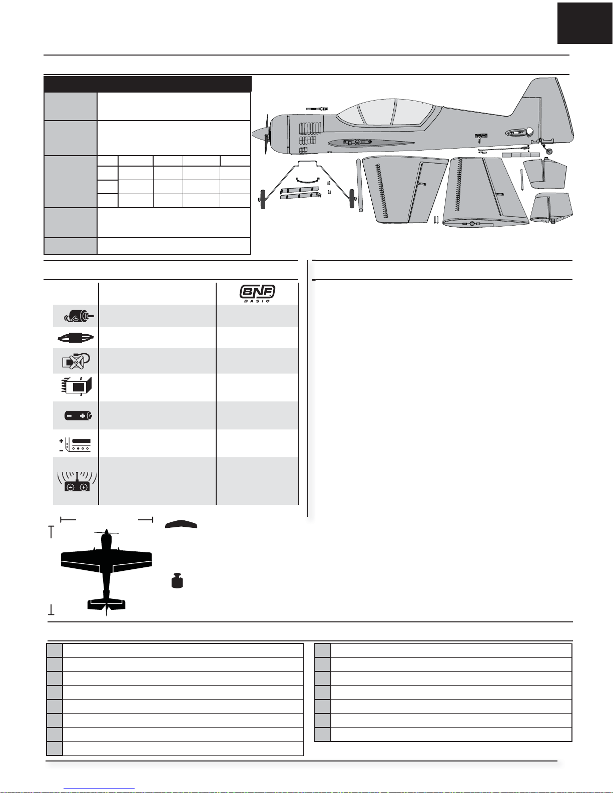
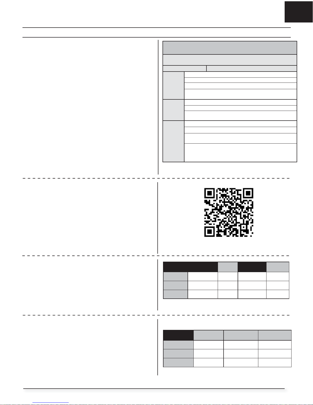
Box Contents
Quick Start Information
Panic
Feature
Choose to fl y your aircraft with the Panic
feature ON or OFF and bind accordingly.
Using the
Panic
Feature
If you choose to fl y with the
Panic feature ON, you will need to follow the
transmitter setup section of this manual.
Set
(Dual Rates
& Expo) in
your
Transmitter
Hi Rate Expo Low Rate Expo
Ail
100% 40% 45% 10%
Ele
100% 35% 25% 10%
Rud
100% 15% 70% 8%
Center of
Gravity (CG)
82mm +/- 3.23 inches back from leading
edge of wing at the fuselage.
Flight Timer
5 minutes
Table of Contents
Specifi cations
Motor: 10-size BL10 brushless
outrunner, 1250Kv (EFLM7225)
Installed
ESC: 40-Amp Switch-Mode BEC
Brushless ESC (EFLA1040LB)
Installed
(4) 13 gram Digital Micro Servo
(EFLR7155)
Installed
Receiver: Spektrum™ AR636A
6-Channel Sport Receiver
(SMPAR636)
Installed
Recommended Battery:
11.1V 3S 2200mAh 30C Li-Po
(EFLB22003S30)
Required to
Complete
Recommended Battery Charger:
3-cell Li-Po battery balancing
charger
Required to
Complete
Recommended Transmitter:
Full-Range 4 channel (or more)
2.4GHz with Spektrum
DSM2
®
/DSMX® technology with
adjustable Dual Rates.
Required to
Complete
T
Transmitter and Receiver Binding / Switching ON and OFF
Panic Recovery Feature ..................................................................4
Transmitter Setup ...........................................................................5
Model Assembly .............................................................................6
Control Horn and Servo Arm Settings ..............................................8
Battery Installation and ESC Arming ................................................8
Center of Gravity (CG) .....................................................................9
Control Direction Test .....................................................................9
AS3X Control Direction Test ..........................................................10
In Flight Trimming .........................................................................10
Flying Tips and Repairs .................................................................11
Post Flight ....................................................................................11
Motor Service ...............................................................................12
Troubleshooting Guide AS3X .........................................................12
Troubleshooting Guide ..................................................................13
AMA National Model Aircraft Safety Code ......................................14
Limited Warranty ..........................................................................15
Contact Information ......................................................................16
FCC Information ............................................................................16
IC Information ...............................................................................16
Compliance Information for the European Union ............................16
Replacement Parts ........................................................................59
Optional Parts ...............................................................................59
40.6 OZ
(1150 g)
42.3 in (1074mm).
(44.0 in 1120mm)
403 sq in.
Prefl ight
1 Remove and inspect contents.
2 Read this instruction manual thoroughly.
3 Charge the fl ight battery.
4 Decide if Panic feature is wanted and Bind appropriately.
5 Setup Transmitter using transmitter setup chart.
6 Fully assemble the airplane.
7 Install the fl ight battery in the aircraft (once it has been fully charged).
8 Check the Center of Gravity (CG).
9 Make sure linkages move freely.
10 Perform the Control Direction Test with the transmitter.
11 Perform the AS3X Control Direction Test with the aircraft.
12 Adjust fl ight controls and transmitter.
13 Perform a radio system Range Test.
14 Find a safe open area to fl y.
15 Plan fl ight for fl ying fi eld conditions.
As of this printing, you are required to register with the FAA if you own this product.
For up-to-date information on how to register with the FAA, please visit https://registermyuas.faa.gov/.
For additional assistance on regulations and guidance on UAS usage, visit knowbeforeyoufl y.org/.
3
EN
Sukhoi SU-29MM
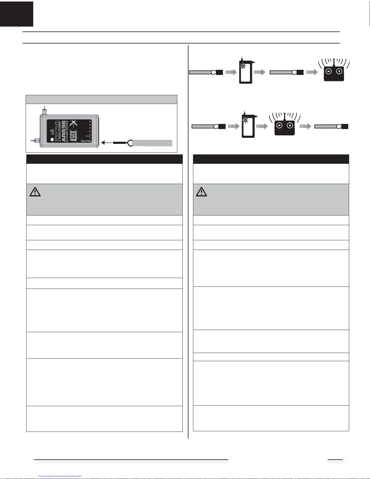
Switching OFF Panic Feature Binding Sequence
Install Bind Plug
RX in Bind Mode
Bind TX to RX
Remove Bind Plug
Install Bind Plug
Remove Bind Plug
RX in Bind Mode
Bind TX to RX
This product requires an approved Spektrum
™
DSM2®/DSMX® compatible
transmitter. Visit www.bindnfl y.com for a complete list of approved transmitters.
The aircraft has an optional panic feature, which can be switched ON or OFF
easily by binding in a specifi c manner as described below.
IMPORTANT: Before binding a transmitter, read the Transmitter Setup section of
this manual to ensure that your transmitter is properly programmed for
this aircraft.
Transmitter and Receiver Binding / Switching ON and OFF Panic Recovery Feature
Bind Plug Installation
BIND PLUG
Binding Procedure / Switching OFF Panic Recovery
IMPORTANT: The included AR636 receiver has been programmed for opera-
tion specifi cally for this aircraft. Refer to the receiver manual for correct
setup if the receiver is replaced or is used in another aircraft.
CAUTION: When using a Futaba® transmitter with a Spektrum DSM
module, you must reverse the throttle channel and rebind. Refer to
your Spektrum module manual for binding and failsafe instructions. Refer to
your Futaba transmitter manual for instructions on reversing the throttle
channel.
1. Make sure the transmitter is powered off.
2. Move the transmitter controls to neutral (fl ight controls: rudder, elevators
and ailerons) or to low positions (throttle, throttle trim). *
3. Install a bind plug in the receiver bind port.
4. Place the aircraft level on its wheels, connect the fl ight battery to the
ESC, then turn ON the switch. The ESC will produce a series of sounds.
One long tone, then 3 short tones confi rm that the LVC is set correctly
for the ESC.
The orange bind LED on the receiver will begin to fl ash rapidly. DO NOT
remove the bind plug at this time.
5. Take 3 steps away from the aircraft /receiver and then power ON the
transmitter while holding the transmitter bind button or switch. Refer to
your transmitter’s manual for specifi c binding instructions.
IMPORTANT: Do not to point the transmitter’s antenna directly at the
receiver while binding.
IMPORTANT: Keep away from large metal objects while binding.
6. The receiver is bound to the transmitter when the orange bind light on
the receiver stays orange. The ESC will also produce a series of three
ascending tones. The tones indicate the ESC is armed, provided the
throttle stick and throttle trim are low enough to trigger arming.
7. Remove the bind plug from the bind port.
IMPORTANT: Once bound, the receiver will retain its bind and last Panic
setting until it has been intentionally changed, even when power is cycled
ON and OFF. However, if you notice that bind has been lost, simply repeat the
binding processs.
Panic OFF Indication
Every time the receiver is powered ON the surfaces will cycle back and forth
once to indicate that Panic feature has been switched OFF.
IMPORTANT: The throttle will not arm if the transmitter’s throttle control is
not put at the lowest position. If you encounter problems, follow the binding instructions and refer to the transmitter troubleshooting guide for other
instructions. If needed, contact the appropriate Horizon Product Support offi ce.
Binding Procedure / Switching ON Panic Recovery
IMPORTANT: The included AR636 receiver has been programmed for opera-
tion specifi cally for this aircraft. Refer to the receiver manual for correct
setup if the receiver is replaced or is used in another aircraft.
CAUTION: When using a Futaba® transmitter with a Spektrum DSM
module, you must reverse the throttle channel and rebind. Refer to
your Spektrum module manual for binding and failsafe instructions. Refer to
your Futaba transmitter manual for instructions on reversing the throttle
channel.
1. Make sure the transmitter is powered off.
2. Move the transmitter controls to neutral (fl ight controls: rudder, elevators
and ailerons) or to low positions (throttle, throttle trim).*
3. Install a bind plug in the receiver bind port.
4. Place the aircraft level on its wheels, connect the fl ight battery to the
ESC, then turn ON the switch. The ESC will produce a series of sounds.
One long tone, then 3 short tones confi rm that the LVC is set correctly
for the ESC. The orange bind LED on the receiver will begin to fl ash
rapidly.
5. Remove the bind plug from the bind port.
6. Take 3 steps away from the aircraft /receiver and then power ON the
transmitter while holding the transmitter bind button or switch. Refer to
your transmitter’s manual for specifi c binding instructions.
IMPORTANT: Do not to point the transmitter’s antenna directly at the
receiver while binding.
IMPORTANT: Keep away from large metal objects while binding.
7. The receiver is bound to the transmitter when the orange bind light on
the receiver stays orange. The ESC will also produce a series of three
ascending tones. The tones indicate the ESC is armed, provided the
throttle stick and throttle trim are low enough to trigger arming.
IMPORTANT: Once bound, the receiver will retain its bind and last Panic
setting until it has been intentionally changed, even when power is cycled
ON and OFF. However, if you notice that bind has been lost, simply repeat the
binding processs.
Panic ON Indication
Every time the receiver is powered ON the surfaces will cycle back and forth
twice with a slight pause at neutral position to indicate that Panic feature is
switched ON.
IMPORTANT: The throttle will not arm if the transmitter’s throttle control is
not put at the lowest position. If you encounter problems, follow the binding instructions and refer to the transmitter troubleshooting guide for other
instructions. If needed, contact the appropriate Horizon Product Support offi ce.
*Failsafe
If the receiver loses transmitter communication, the failsafe will activate. When activated, failsafe moves the throttle channel to its preset failsafe position (low
throttle) that was set during binding. All other channels move to actively level the aircraft in fl ight.
Switching ON Panic Feature Binding Sequence
4
EN
Transmitter Setup
If you intend on using the Panic Recovery feature, it is important to follow this
transmitter setup chart to assign your transmitter switches correctly to operate
the Panic Recovery feature.
Use the provided charts to guide you through transmitter setup. Locate your
specifi c transmitter in the chart and follow the numbered setup sequence. The
ending results will be as follows:
Panic Recovery : Flap Switch (DX6i)
Trainer/Bind button (DX7S, DX8, DXe)
Bind button (DX6, DX8G2, DX9, DX18, DX20)
R-Tip (DX10t)
If you don’t intend to use Panic recovery, you do not need to follow this
transmitter setup.
DXe Transmitter
Your aircraft is also compatible with Spektrum DXe transmitter. However, it is
recommended to download the latest AirWare
™
software from SpektrumRC.
com before downloading the model setup for this aircraft. The USB programming cable (SPMA3065) (sold separately) must be used for AirWare™ software
updates.
Model Setup
We recommend downloading the Sukhoi SU-29MM DXe model setup available
at www.spektrumrc.com. Use your PC and USB programming cable SPMA3065
(sold separately).
Dual Rates and Expo
Set Dual Rates and Expo per the chart for initial fl ights. After fi rst fl ight you may
adjust these in your transmitter to suit your fl ying style.
Factory Gain Settings
The following chart is a list of the default factory gain settings that are programmed into your AR636 receiver for this aircraft.
To adjust these gain settings, or program them into a new AR636 receiver, use
your PC and USB programming cable SPMA3065 (sold separately), or mobile
app with audio interface programming cable SPMA3081 (sold separately).
Computerized Transmitter Setup
(DX6i, DX6, DX7, DX7S, DX8, DX8G2, DX9, DX10t, DX18 and DX20)
Start all transmitter programming with a blank ACRO model (do a model reset),
then name the model.
Set Servo Travel to: 100%
DX6i
1. Go to the SETUP LIST MENU
2. Set MODEL TYPE: ACRO
3. Go to ADJUST LIST MENU
4. Set FLAPS: Norm 100 Flap
LAND 100 Flap
DX7S
DX8
1. Go to the SYSTEM SETUP
2. Set MODEL TYPE: AIRPLANE
3. Set SWITCH SELECT: Change all to INH:
Then TRAINER: AUX1
DX6
DX7
DX8 (Gen2)
DX9
DX10t
DX18
DX20
1. Go to the SYSTEM SETUP
2. Set MODEL TYPE: AIRPLANE
3. Set AICRAFT TYPE:
WING: NORMAL
4. Go to CHANNEL ASSIGN:
NEXT:
Channel Input Confi g:
Set AUX1: I (DX10t: AUX1: R-TIP)
High Rate Expo Low Rate Expo
Aileron 100% 40% 45% 10%
Elevator 100% 35% 25% 10%
Rudder 100% 15% 70% 8%
Scan the QR code for model setup page for the DXe Transmitter. Then
locate the sukhoi SU-29MM in the list of aircaft.
Roll Pitch Yaw
Rate Gain 17% 17% 40%
Heading Gain NA NA NA
Priority 160% 160% 160%
5

EN
Sukhoi SU-29MM
Model Assembly
Landing Gear Installation
1. Install the landing gear strut (A) as shown.
2. Install the U-cover (B) on the fuselage.
3. Install the fairings (C) on the strut.
4. Secure the landing gear assembly by using 4 screws (D).
Tip: Carefully support the aircraft while installing or removing screws.
Disassemble in reverse order.
A
B
C
2 X 10mm (4)
D
Wing Installation
1. Slide the wing tube (A) into the fuselage.
CAUTION: DO NOT crush or otherwise damage the wiring when
attaching the wing to the fuselage.
2. Install the left and right wing (B and C) over the wing tube and into the
wing slot of the fuselage while inserting the aileron servo connectors
through the provided holes.
3. Invert the fuselage so the landing gear is facing up. Secure the left and
right wings to the fuselage using the included screws (D).
4. Remove the canopy (E) from the fuselage.
Tip: If needed, use hemostats or pliers to pull the servo connectors into
the fuselage.
5. Connect the aileron servos from the wings to the Y-harness connectors in
the fuselage. The left and right aileron servos can be connected to either
side of the Y-harness.
6. Replace the canopy.
Disassemble in reverse order.
IMPORTANT: Correct operation of the AS3X system requires connection of
both ailerons to the included Y-harness and the AILE channel of the receiver.
A
B
C
E
E
3 X 22mm (2)
D
6
 Loading...