

Horizon Hobby NIGHT VisionAire Instruction Manual
NIGHT VisionAire
®
Instruction Manual
Bedienungsanleitung
Manuel d’utilisation
Manuale di Istruzioni
EN
As the user of this product, you are solely responsible for operating in a manner that does not endanger yourself and others or result in damage to the
product or the property of others.
• Always keep a safe distance in all directions around your model to avoid
collisions or injury. This model is controlled by a radio signal subject to
interference from many sources outside your control. Interference can cause
momentary loss of control.
• Always operate your model in open spaces away from full-size vehicles,
traffi c and people.
• Always carefully follow the directions and warnings for this and any optional
support equipment (chargers, rechargeable battery packs, etc.).
• Always keep all chemicals, small parts and anything electrical out of the
reach of children.
• Always avoid water exposure to all equipment not specifi cally designed and
protected for this purpose. Moisture causes damage to electronics.
• Never place any portion of the model in your mouth as it could cause serious
injury or even death.
• Never operate your model with low transmitter batteries.
• Always keep aircraft in sight and under control.
• Always use fully charged batteries.
• Always keep transmitter powered on while aircraft is powered.
• Always remove batteries before disassembly.
• Always keep moving parts clean.
• Always keep parts dry.
• Always let parts cool after use before touching.
• Always remove batteries after use.
• Always ensure failsafe is properly set before fl ying.
• Never operate aircraft with damaged wiring.
• Never touch moving parts.
NOTICE
All instructions, warranties and other collateral documents are subject to change at the sole discretion of Horizon Hobby, LLC. For up-to-date product
literature, visit www.horizonhobby.com and click on the support tab for this product.
Meaning of Special Language:
The following terms are used throughout the product literature to indicate various levels of potential harm when operating this product:
NOTICE: Procedures, which if not properly followed, create a possibility of physical property damage AND little or no possibility of injury.
CAUTION: Procedures, which if not properly followed, create the probability of physical property damage AND a possibility of serious injury.
WARNING: Procedures, which if not properly followed, create the probability of property damage, collateral damage, and serious injury OR create a high
probability of superfi cial injury.
WARNING: Read the ENTIRE instruction manual to become familiar with the features of the product before operating. Failure to operate the product
correctly can result in damage to the product, personal property and cause serious injury.
This is a sophisticated hobby product. It must be operated with caution and common sense and requires some basic mechanical ability. Failure to operate this Product in a safe and responsible manner could result in injury or damage to the product or other property. This product is not intended for use by
children without direct adult supervision. Do not use with incompatible components or alter this product in any way outside of the instructions provided by
Horizon Hobby, LLC. This manual contains instructions for safety, operation and maintenance. It is essential to read and follow all the instructions and warnings in the manual, prior to assembly, setup or use, in order to operate correctly and avoid damage or serious injury.
Safety Precautions and Warnings
14
+
AGE RECOMMENDATION:
Not for children under 14
years. This is not a toy.
WARNING AGAINST COUNTERFEIT PRODUCTS: If you ever need to replace your Spektrum receiver found
in a Horizon Hobby product, always purchase from Horizon Hobby, LLC or a Horizon Hobby authorized dealer to ensure authentic high-quality Spektrum product. Horizon Hobby, LLC disclaims all support and warranty with regards,
but not limited to, compatibility and performance of counterfeit products or products claiming compatibility with
DSM or Spektrum.
To register your product online, visit www.e-fl iterc.com
2
EN
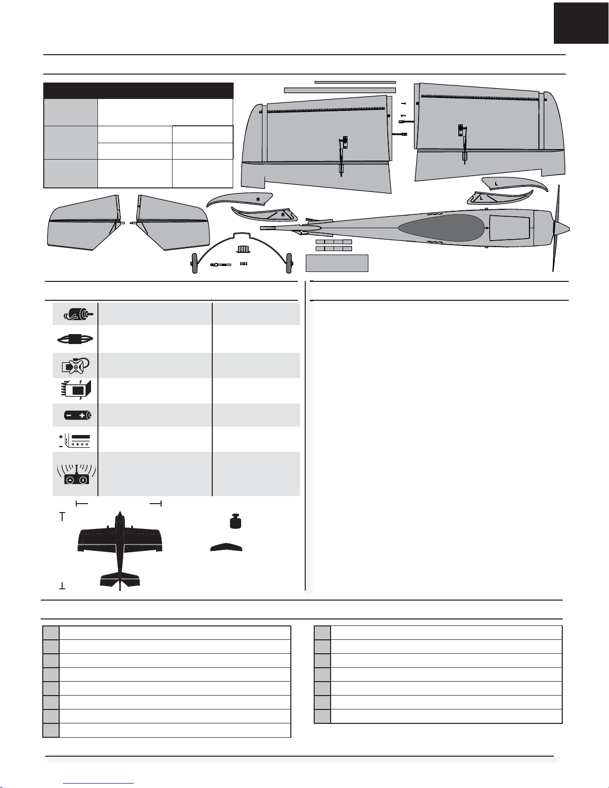
Box Contents
Quick Start Information
Transmitter
Setup
Set up your transmitter using the
transmitter setup chart.
Dual Rates
High Low
100% 70%
Flight Timer
Setting
First fl ight 4 Min. 6 Min.
Table of Contents
51.0 oz
(1450 g)
42.5 in (1088mm)
45 in (1143mm)
Specifi cations
Motor: BL10 Brushless outrunner
1250Kv
Included
ESC: 40-Amp Lite Pro Switch
Mode BEC Brushless ESC (V2)
(EFLA1040LB)
Installed
(4) Servos (EFLR7155) Installed
Receiver: Spektrum™ AR636
6-Channel Sport Receiver
Installed
Battery: 2200mA 11.1V 3S 25C
Li-Po (EFLB22003S30)
Required to
Complete
Battery Charger: 3-cell Li-Po
battery balancing charger
Required to
Complete
Recommended Transmitter:
Full-Range 2.4GHz with
Spektrum
™
DSM2®/DSMX®
technology. (DX4e and above)
Required to
Complete
T
539 sq in
(34.8 sq dm)
Prefl ight
1 Remove and inspect contents.
2 Read this instruction manual thoroughly.
3 Charge fl ight battery.
4 Setup Transmitter using transmitter setup chart.
5 Fully assemble airplane.
6 Install the fl ight battery in the aircraft (once it has been fully charged).
7 Check the Center of Gravity (CG).
8 Bind aircraft to your transmitter.
9 Make sure linkages move freely.
10 Perform the Control Direction Test with the transmitter.
11 Perform the AS3X Control Direction Test with the aircraft.
12 Adjust fl ight controls and transmitter.
13 Perform a radio system Range Test.
14 Find a safe open area to fl y.
15 Plan fl ight for fl ying fi eld conditions.
SAFE® Technology Flight Modes .........................................................4
Transmitter Setup for this SAFE® Technology Aircraft .........................5
Model Assembly ................................................................................6
Model Assembly Continued ................................................................7
Trimming ........................................................................................... 8
Control Horn and Servo Arm Settings .................................................8
Transmitter and Receiver Binding .......................................................9
Battery Installation and ESC Arming .................................................10
Center of Gravity (CG) .....................................................................11
Control Direction Tests .....................................................................11
AS3X Control Direction Test ............................................................12
Flying Tips and Repairs ....................................................................13
Guidlines for Flying 3D .....................................................................14
Post Flight .......................................................................................14
Power Component Service ...............................................................15
Troubleshooting Guide SAFE ............................................................15
Troubleshooting Guide .....................................................................16
AMA National Model Aircraft Safety Code .........................................17
Limited Warranty .............................................................................18
Contact Information .........................................................................19
FCC Information ...............................................................................19
IC Information ..................................................................................19
Compliance Information for the European Union ...............................19
Replacement Parts ...........................................................................70
Optional Parts ..................................................................................71
3
EN
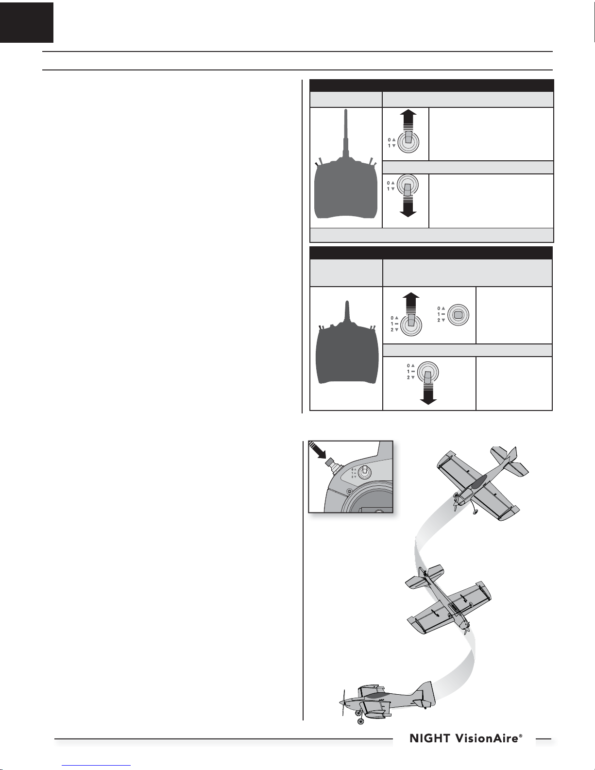
SAFE® Technology Flight Modes
This aircraft has 2 selectable fl ight modes and a Panic Recovery feature. It is
extremely important to follow the Transmitter Setup section of this manual
before binding your transmitter to this aircraft .
Precision Mode:
This mode uses low rates and low gains to deliver precise response at high
airspeeds. Use this mode to trim the aircraft and fl y fast precision maneuvers.
3D Mode:
This mode uses high rates and high gains to deliver extreme maneuverability
with maximum stability at low airspeeds. Use this mode for slow fl ying and 3D
maneuvers such as Hovers and Harriers. Flying at high speed in this mode
could cause oscillation.
Panic Recovery Mode
If you feel you have lost control of the aircraft (in any mode), hold the Panic
Recovery button/switch. The SAFE technology will return the aircraft to upright
fl ight.
Always fl y at a safe altitude, as Panic Recovery may cause the aircraft to lose
altitude while returning to upright fl ight. Release the Panic Recovery button/
switch to turn off Panic mode and return to the current SAFE fl ight mode with
full stick control again.
IMPORTANT: If the aircraft is upside down when the Panic Recovery button/
switch is pressed, suffi cient altitude may be required for the aircraft to return
to upright fl ight.
CH 5
DX4e shown. Panic Button /
Switch may vary depending
on Transmitter model. See
Transmitter setup for more
info.
2 Position Gear/Ch 5 Switch Transmitters
DX6i and DX5e,
DX4e (older versions)
Precision Mode (Low Rate)
Position 0 is Precision Mode
3D Mode (High Rate)
Position 1 is 3D Mode
Important: DX6i ch5 has to be reversed.
3 Position Gear/Ch 5 Switch Transmitters
DX4e, DX5e, DX6,
DX7S, DX8, DX9,
DX18, DX10t
Precision Mode (Low Rate)
Positions 0 and 1 are
Precision Mode
3D Mode (High Rate)
Position 2 is 3D Mode
4

EN
It is extremely important to folow these transmitter setup charts to assign your
transmitter switches correctly to operate the fl ight modes and Panic Recovery
correctly.
The installed AR636 receiver has been programmed for operation specifi cally
in this aircraft. The fl ight modes can be changed in fl ight using a toggle switch
(Gear/Channel 5 Switch).
Use the provided charts to guide you through transmitter setup. Locate your
specifi c transmitter in the chart and follow the numbered setup sequence. The
ending results will be:
– Toggles between fl ight modes: Gear/Channel 5 Switch
– Operates Panic Recovery: Flap Switch (DX6i)
Trainer/Bind button (DX7S, DX8)
Bind button (DX6, DX9, DX18)
R-Tip (DX10t)
Non-Computerized Transmitter Setup
(DX4e and DX5e)
Before binding a non-computerized transmitter, ensure all servo reversing
is set to normal and trim is at center.
Computerized Transmitter Setup
(DX6i) • (DX7S, DX8) • (DX6, DX9 and DX18) • (DXt10)
Start all transmitter programming with a blank ACRO model (do a model
reset), then name the model.
Set Dual Rates to: HIGH 100% LOW 70%
Set Servo Travel to: 100%
DX6i
1. Go to the SETUP LIST MENU
2. Set MODEL TYPE: ACRO
3. Set REVERSE: Gear Channel
4. Go to ADJUST LIST MENU
5. Set FLAPS: Norm 100, LAND 100
Resulting in:
The Gear switch operates the 2 SAFE modes.
Gear 0: = Precision Mode
Gear 1: = 3D Mode
The Flap switch operates Panic Recovery:
Position 0=Off
Position 1=On. (not a momentary switch)
DX7S and DX8
1. Go to the SYSTEM SETUP
2. Set MODEL TYPE: AIRPLANE
3. Set SWITCH SELECT: Change all to INH:
Then TRAINER: AUX1
Then F-Mode: GEAR
4. Go to the FUNCTION LIST
5. Set SERVO SETUP: Reverse AUX1
Resulting in:
F-Mode Switch operates the 2 SAFE modes.
0 and 1 = Precision Mode
2 = 3D Mode
The Trainer/Bind button operates Panic Recovery
DX6, DX9, DX18 and DX10t
1. Go to the SYSTEM SETUP
2. Set MODEL TYPE: AIRPLANE
3. Set WING TYPE: NORMAL
4. Go to CHANNEL ASSIGN:
NEXT:
Channel Input Confi g:
Set GEAR: B (DX10t: GEAR: A)
Set AUX1: I (DX10t: AUX1: R-TIP)
5. Go to the FUNCTION LIST
6. Set SERVO SETUP: Reverse AUX1
Resulting in:
Switch B (DX10t: A) operates the 2 SAFE modes.
0 and 1 = Precision Mode
2 = 3D Mode
The Bind/I button (DX10t: R-TIP) operates Panic
Recovery
IMPORTANT: After you set up your model, always rebind the transmitter
and receiver to set the desired failsafe positions.
Transmitter Setup for this SAFE® Technology Aircraft
DX7S/DX8
DX6i
Panic Switch
Flight Modes
Panic Switch
Flight Modes
DX10t
Flight Modes
Panic Switch
DX6, DX9, DX18
Panic Switch
Flight Modes
5
EN
Model Assembly
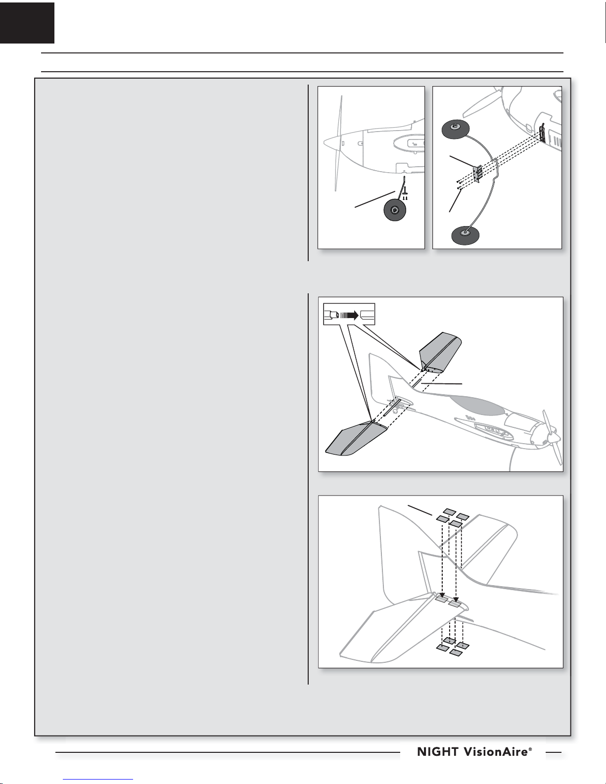
Landing Gear Installation
1. Install the landing gear strut (A) with the wheels raked forward as shown.
2. Install the cover (B) on the fuselage using 4 screws (C).
Disassemble in reverse order.
Horizontal Tail Installation
1. Slide the horizontal tail tube (A) into the hole in the rear of the fuselage.
2. Install the 2 piece (left and right) horizontal tail as shown. Ensure the control horn faces down.
3. Connect the LED connectors to either side of the LED light harness in the
fuselage.
4. Apply 8 pieces of tape (B) to the fuselage mounts (two on the top and
bottom of each half of the horizontal tail).
5. Attach the clevis to the elevator control horn (see instructions for clevis
connection).
6. When needed, disassemble in reverse order.
B
A
C
A
B
6
EN
Model Assembly Continued
A
B
C
A
B
C
D
F
E
F
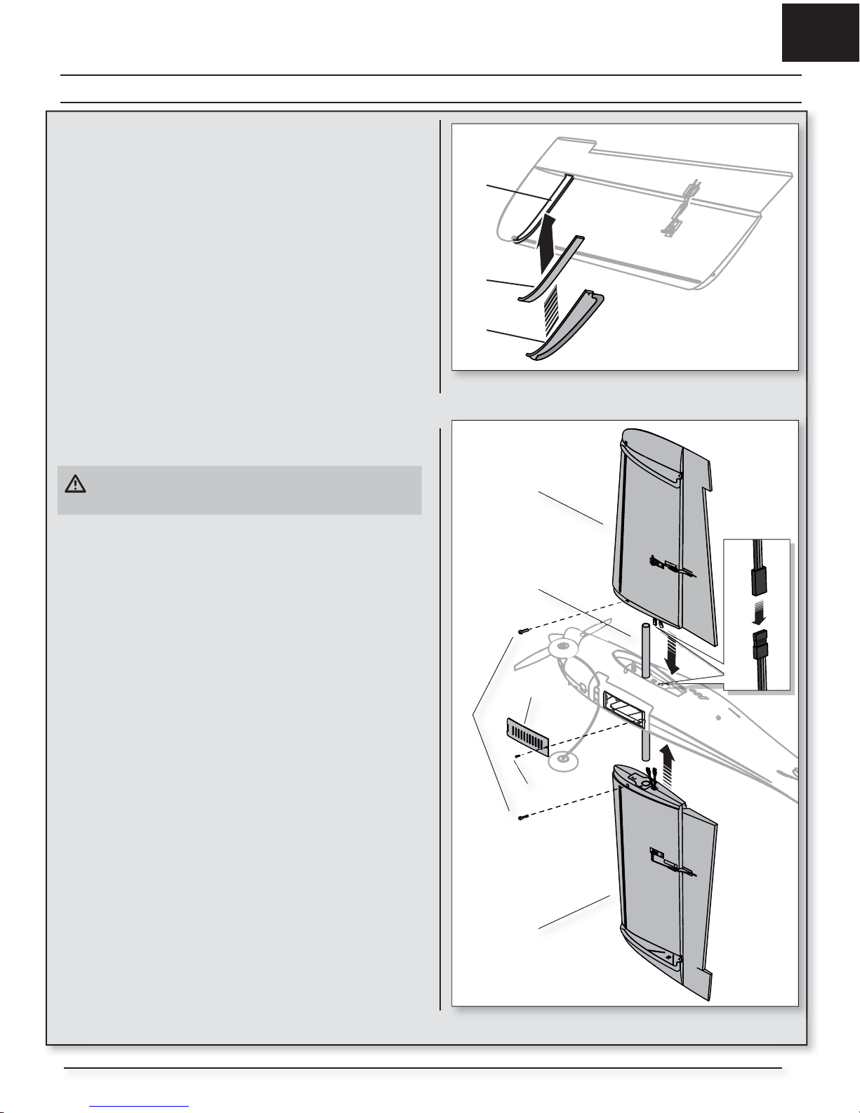
SFG Installation
1. Carefully apply the included tape (A) to the wing fence base.
2. Align and install the left and right (marked L and R) top and bottom wing
fences (B) into the respective wing slots (C). The bottom fences have
integrated plastic skids, as shown.
If desired, apply a small amount of thin CA (cyanoacrylate adhesive)
to the fences and wings.
Wing Installation
1. Slide the wing tube (A) into the fuselage.
CAUTION: DO NOT crush or otherwise damage the wiring when
attaching the wing to the fuselage.
2. Install the left and right wing (B and C) over the wing tube and into the
wing slot of the fuselage while inserting the aileron servo and LED
connectors through the provided holes.
3. Invert the fuselage so the landing gear is facing up. Secure the left and
right wings to the fuselage using the included screws (D).
4. Remove the screw (E) and the receiver cover (F) from the bottom of the
fuselage.
Tip: If needed, use hemostats or pliers to pull the servo and LED connectors
into the fuselage.
5. Connect the aileron servos from the wings to the Y-harness connectors in
the fuselage. The left and right aileron servos can be connected to either
side of the Y-harness.
6. Connect the LED connectors to either side of the LED light harness in the
fuselage.
7. Replace the receiver cover and the screw.
Disassemble in reverse order.
IMPORTANT: Correct operation of the AS3X® system requires connection of
both ailerons to the included Y-harness and the AILE channel of the receiver.
7
 Loading...