

Page 1
www.modellmarkt24.ch; www.modellmarkt24.de
Instruction Manual
Bedienungsanleitung
Manuel d’utilisation
Manuale di Istruzioni
SAFE® Select Technology, Optional Flight Envelope Protection
Maule M7
www.modellmarkt24.ch; www.modellmarkt24.de
Page 2
www.modellmarkt24.ch; www.modellmarkt24.de
EN
2
Maule M7
As the user of this product, you are solely responsible for operating in a
manner that does not endanger yourself and others or result in damage to the
product or the property of others.
• Always keep a safe distance in all directions around your model to avoid
collisions or injury. This model is controlled by a radio signal subject to
interference from many sources outside your control. Interference can
cause momentary loss of control.
• Always operate your model in open spaces away from full-size vehicles,
traffi c and people.
• Always carefully follow the directions and warnings for this and any
optional support equipment (chargers, rechargeable battery packs, etc.).
• Always keep all chemicals, small parts and anything electrical out of the
reach of children.
• Always avoid water exposure to all equipment not specifi cally designed
and protected for this purpose. Moisture causes damage to electronics.
• Never place any portion of the model in your mouth as it could cause
serious injury or even death.
• Never operate your model with low transmitter batteries.
• Always keep aircraft in sight and under control.
• Always use fully charged batteries.
• Always keep transmitter powered on while aircraft is powered.
• Always remove batteries before disassembly.
• Always keep moving parts clean.
• Always keep parts dry.
• Always let parts cool after use before touching.
• Always remove batteries after use.
• Always ensure failsafe is properly set before fl ying.
• Never operate aircraft with damaged wiring.
• Never touch moving parts.
NOTICE
All instructions, warranties and other collateral documents are subject to change at the sole discretion of Horizon Hobby, LLC. For up-to-date product
literature, visit www.horizonhobby.com and click on the support tab for this product.
Meaning of Special Language:
The following terms are used throughout the product literature to indicate various levels of potential harm when operating this product:
WARNING: Procedures, which if not properly followed, create the probability of property damage, collateral damage, and serious injury OR create a high
probability of superfi cial injury.
CAUTION: Procedures, which if not properly followed, create the probability of physical property damage AND a possibility of serious injury.
NOTICE: Procedures, which if not properly followed, create a possibility of physical property damage AND little or no possibility of injury.
WARNING: Read the ENTIRE instruction manual to become familiar with the features of the product before operating. Failure to operate the product
correctly can result in damage to the product, personal property and cause serious injury.
This is a sophisticated hobby product. It must be operated with caution and common sense and requires some basic mechanical ability. Failure to operate this
Product in a safe and responsible manner could result in injury or damage to the product or other property. This product is not intended for use by children
without direct adult supervision. Do not use with incompatible components or alter this product in any way outside of the instructions provided by Horizon
Hobby, LLC. This manual contains instructions for safety, operation and maintenance. It is essential to read and follow all the instructions and warnings in the
manual, prior to assembly, setup or use, in order to operate correctly and avoid damage or serious injury.
Safety Precautions and Warnings
14
+
AGE RECOMMENDATION:
Not for children under 14
years. This is not a toy.
WARNING AGAINST COUNTERFEIT PRODUCTS: If you ever need to replace your Spektrum receiver
found in a Horizon Hobby product, always purchase from Horizon Hobby, LLC or a Horizon Hobby
authorized dealer to ensure authentic high-quality Spektrum product. Horizon Hobby, LLC disclaims all support
and warranty with regards, but not limited to, compatibility and performance of counterfeit products or products
claiming compatibility with DSM or Spektrum technology.
www.modellmarkt24.ch; www.modellmarkt24.de
Page 3
www.modellmarkt24.ch; www.modellmarkt24.de
EN
3
Safety Precautions and Warnings .................................................................... 2
Box Contents ..................................................................................................3
Specifi cations ................................................................................................. 3
Table of Contents ............................................................................................ 3
SAFE
®
Select Technology ................................................................................ 4
Prefl ight .......................................................................................................... 4
Transmitter Setup .......................................................................................... 4
Model Assembly ............................................................................................. 5
Scale Accessories Optional ............................................................................. 7
Float Installation Optional ................................................................................ 7
Receiver Access .............................................................................................. 8
Battery Installation and ESC Arming ................................................................ 8
Transmitter and Receiver Binding / Switching ON and OFF SAFE Select .......... 9
SAFE
®
Select Switch Designation ................................................................. 10
Control Horn and Servo Arm Settings ............................................................ 10
Center of Gravity (CG) .................................................................................. 10
AS3X Control Direction Test .......................................................................... 11
In Flight Trimming ......................................................................................... 11
Flying Tips and Repairs ................................................................................. 12
PNP Receiver Selection and Installation ........................................................ 12
Post Flight..................................................................................................... 13
Motor Service ...............................................................................................13
Troubleshooting Guide AS3X .........................................................................13
Troubleshooting Guide .................................................................................. 14
AMA National Model Aircraft Safety Code ...................................................... 15
Limited Warranty .......................................................................................... 16
Contact Information ...................................................................................... 16
FCC Information ............................................................................................ 17
IC Information ............................................................................................... 17
Compliance Information for the European Union ............................................ 17
Recommended Receivers ............................................................................. 18
Replacement Parts ........................................................................................ 64
Optional Parts ............................................................................................... 65
If you own this product, you may be required to register with the FAA.
For up-to-date information on how to register with the FAA, visit https://
registermyuas.faa.gov/.
For additional assistance on regulations and guidance on UAS usage, visit
knowbeforeyoufl y.org/.
To receive product updates, special offers and more, register your
product online at www.e-fl iterc.com
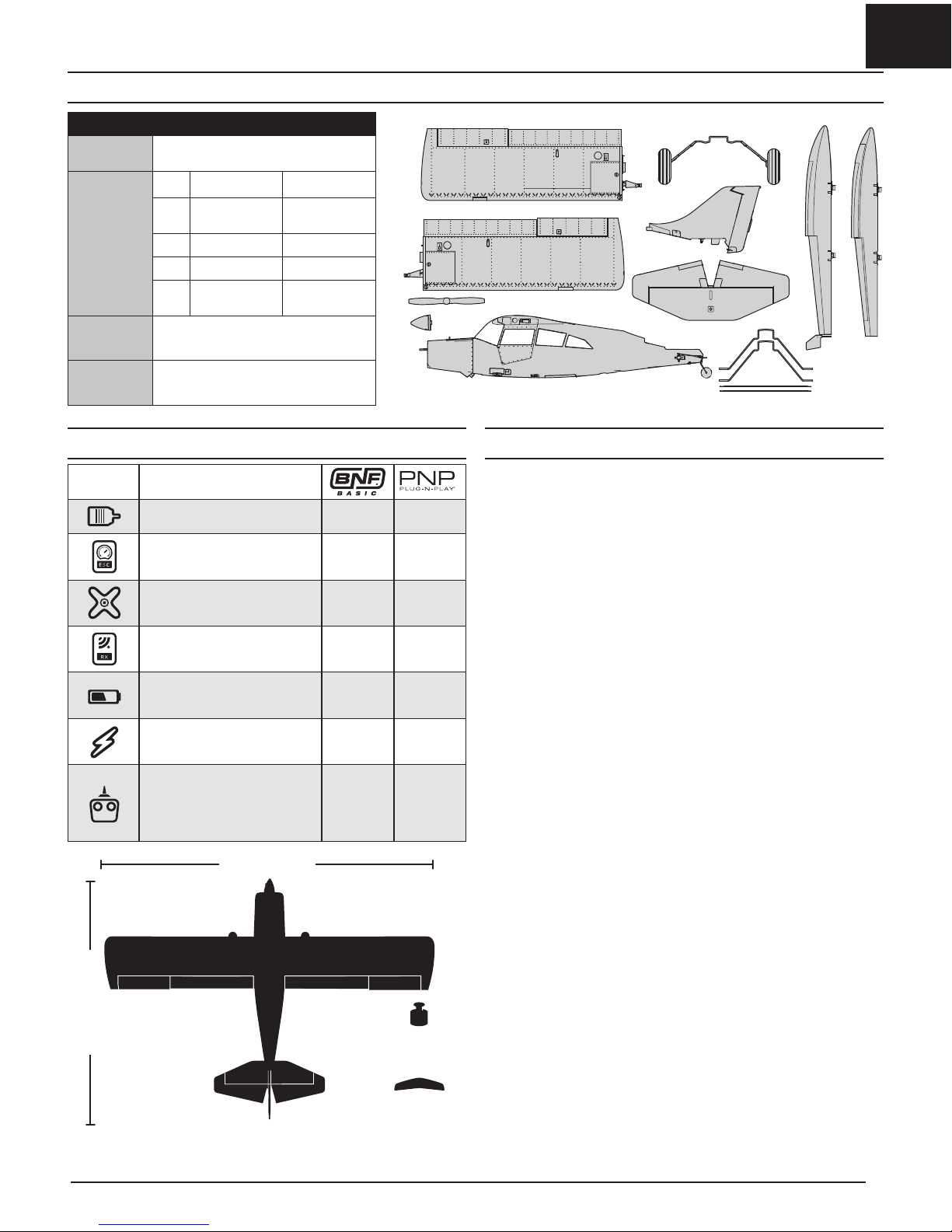
Box Contents
Quick Start Information
Transmitter
Setup
Set up your transmitter using the
transmitter setup chart
Dual Rates
Hi Rate Low Rate
Ail
S30mm
T25mm
S22mm
T18mm
Ele 30mm 20mm
Rud 18mm 13mm
Flaps
Landing
T=40mm
Takeoff
T=30mm
Center of
Gravity (CG)
55 – 70mm back from leading edge of
wing at the fuselage.
Flight Timer
Setting
4 minutes
Table of ContentsSpecifi cations
Motor: 15BL (EFL5367) Installed Installed
ESC: 40A ESC (EFLA1040W) Installed Installed
9 gram servo (SPMSA330) Installed Installed
Receiver: Spektrum™ AR636A
6-Channel Sport Receiver
(SPMAR636A)
Installed
Required to
Complete
Recommended Battery: 11.1V
3S–4S 2200–3200mAh 30C Li-Po
(EFLB22003S30, EFLB32003S30)
Required to
Complete
Required to
Complete
Recommended Battery Charger:
3-cell Li-Po battery balancing
charger
Required to
Complete
Required to
Complete
Recommended Transmitter:
Full-Range 6 channel (or more)
2.4GHz with Spektrum
DSM2
®
/DSMX® technology with
adjustable Dual Rates
Required to
Complete
Required to
Complete
59 in (1500mm)
43.3 in (1100mm)
66 oz (1871g)
557 sq/in (35.9
sq/dm)
www.modellmarkt24.ch; www.modellmarkt24.de
Page 4
www.modellmarkt24.ch; www.modellmarkt24.de
EN
4
Maule M7
Prefl ight
Transmitter Setup
IMPORTANT: After you set up your model, always rebind the transmitter and
receiver to set the desired failsafe positions.
Dual Rates
At fi rst fl y with Low Rate.
NOTICE: To ensure AS3X
®
technology functions properly, do not lower rate
values below 50%. If lower rates are desired, manually adjust the position of
the pushrods on the servo arm.
NOTICE: If oscillation occurs at high speed, refer to the Troubleshooting
Guide for more information.
Expo
After fi rst fl ights, you may adjust expo in your transmitter.
Computerized Transmitter Setup
Start all transmitter programming with a blank ACRO model (perform a model
reset), then name the model.
Set Dual Rates to
HIGH 100%
LOW 70%
Set Servo Travel to 100%
Set Throttle Cut to -130%
DXe
Refer to spektrumrc.com for the appropriate download setup.
DX6i
1. Go to the SETUP LIST MENU
2. Set MODEL TYPE: ACRO
3. Go to ADJUST LIST MENU
4. Set FLAPS: Norm 100 Flap Elev 0
LAND 100 Flap Elev 10
DX7S
DX8
1. Go to the SYSTEM SETUP
2. Set MODEL TYPE: AIRPLANE
3. Set WING TYPE: 1 AIL 1 FLAP
4. Go to the FUNCTION LIST
5. Set FLAP SYSTEM: Choose Flap
NORM: -100% FLAP
MID: 0% FLAP 4% Elevator
LAND: 100% FLAP 10% Elevator
SPEED 2.0S: SWITCH = FLAP
DX6e
DX6 (Gen2)
DX7 (Gen2)
DX8 (Gen2)
DX9
DX10t
DX18
DX20
iX12
1. Go to the SYSTEM SETUP
2. Set MODEL TYPE: AIRPLANE
3. Set AICRAFT TYPE:
WING: 1 AIL 1 FLAP
4. Go to the FUNCTION LIST
5. Set FLAP SYSTEM:
SELECT SWITCH D:
POS 0: -100% FLAP
POS 1: 0% FLAP 4% Elevator
POS 2: 100% FLAP 10% Elevator
SPEED 2.0
SAFE® Select Technology
The evolutionary SAFE® Select technology can offer an extra level of protection
so you can perform the fi rst fl ight with confi dence. No complex transmitter
programming is required. Just follow the simple bind process to make the
SAFE Select system active. When activated, bank and pitch limitations keep
you from over-controlling and automatic self-leveling makes recovery from
risky or confusing attitudes as simple as releasing the sticks. In fact, with the
aileron, elevator and rudder sticks in the neutral position, SAFE Select will
automatically keep the airplane in a straight and level attitude.
Expand the advantage of what SAFE
®
Select technology offers by assigning it
to a switch. No transmitter programming is required and you’ll be able to turn
the system ON and OFF with the fl ip of a switch. For example, turn SAFE select
ON for takeoffs to counter the torque of the propeller. Turn it OFF in fl ight for
unrestricted aerobatic performance, and turn it back ON when a buddy wants
to try out your cool aircraft. Turn SAFE Select ON for landings. As you drop the
fl aps, SAFE Select reduces your workload by compensating for pitch changes
automatically, regardless of throttle position. It will help keep the correct pitch
attitude and wings level during the fi nal approach. Whether you’re a beginner
or an expert, SAFE Select can make your fl ights a great experience.
When the normal bind process is followed, the SAFE Select system is
disabled, leaving specially tuned AS3X
®
technology in place to deliver a pure,
unrestricted fl ight experience.
1. Remove and inspect contents.
2. Read this instruction manual thoroughly.
3. Charge the fl ight battery.
4. Setup Transmitter using transmitter setup chart.
5. Fully assemble the airplane.
6. Install the fl ight battery in the aircraft (once it has been fully charged).
7. Check the Center of Gravity (CG).
8. Bind the aircraft to your transmitter.
9. Make sure linkages move freely.
10. Test the fl ap operation.
11. Perform the Control Direction Test with the transmitter.
12. Perform the AS3X Control Direction Test with the aircraft.
13. Adjust fl ight controls and transmitter.
14. Perform a radio system Range Test.
15. Find a safe open area to fl y.
16. Plan fl ight for fl ying fi eld conditions.
www.modellmarkt24.ch; www.modellmarkt24.de
Page 5
www.modellmarkt24.ch; www.modellmarkt24.de
EN
Model Assembly
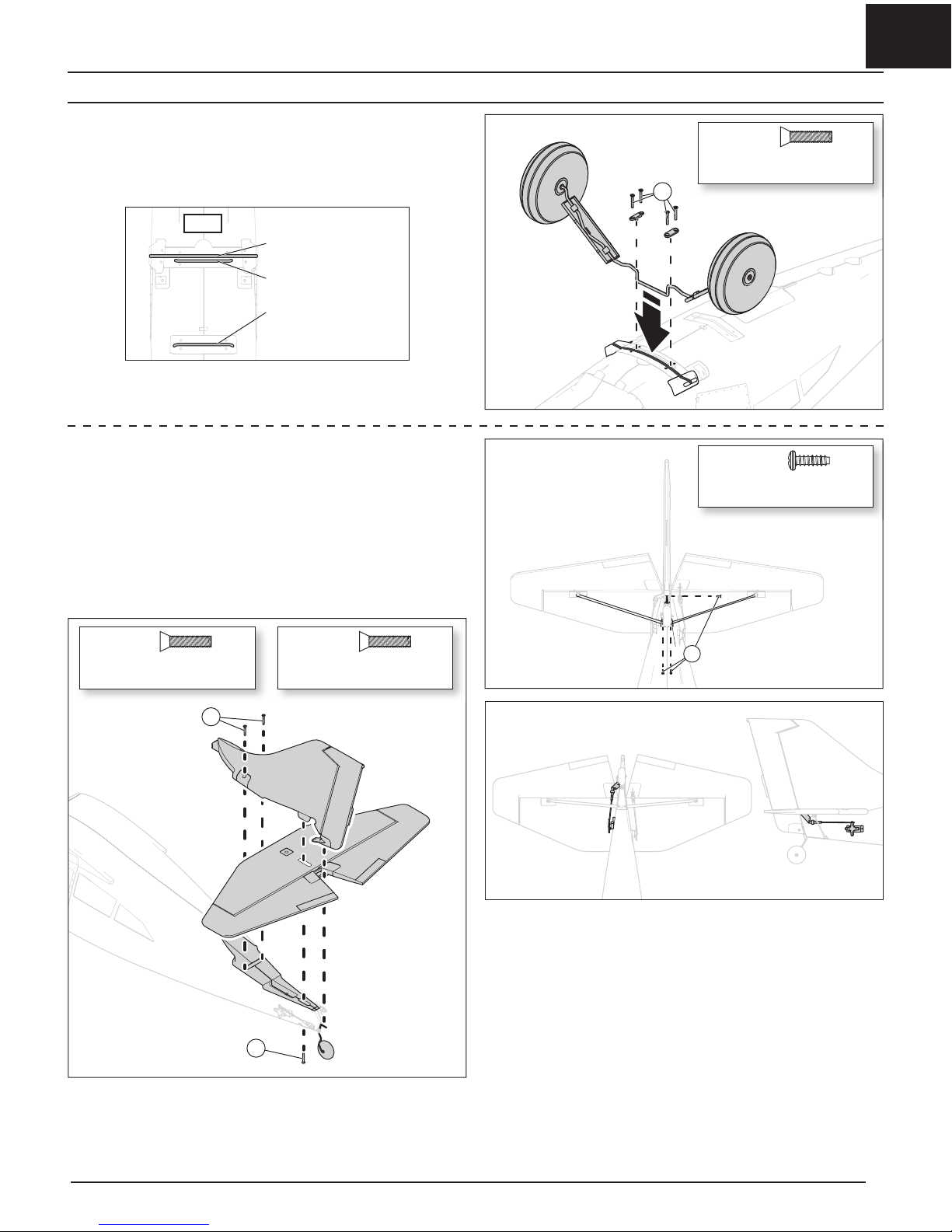
Tail Installation
1. Insert the vertical stabilizer into the slot in the horizontal stabilizer.
2. Install the tail assembly and insert the tail wheel wire into the rudder.
3. Secure the Tail assembly in place with two 3 x 16mm hex head screws (B)
from the top and one 3 x 16mm screw (C) from the bottom.
4. Flex the tail struts slightly and insert them into the pockets on the fuselage.
Screw them in place with 2 x 8mm screws (D).
5. Secure the tail wheel assembly in place with a 2 x 8mm phillips head screw (D).
6. Connect the clevises on the elevator and rudder pushrods to the control
horns on the outermost holes.
B
C
D
Landing Gear Installation
1. Insert the landing gear assembly into the front mounting location on the
bottom of the fuselage as shown.
2. Secure the landing gear into place with the four included 3 x 16mm (A)
screws and mounting straps.
B
A
3 x 16mm
Tapered hex head machine
B
3 x 16mm
Tapered hex head machine
C
2 x 8mm
Phillips head self tapping
D
3 x 16mm
Tapered hex head machine
A
5
Front
Wheeled landing gear slot
Front fl oat strut slot
Rear fl oat strut slot
www.modellmarkt24.ch; www.modellmarkt24.de
Page 6
www.modellmarkt24.ch; www.modellmarkt24.de
EN
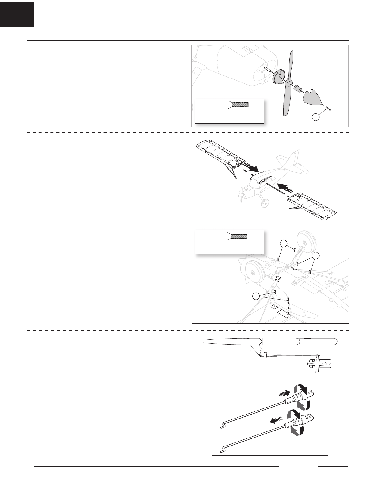
Model Assembly Continued
A
B
B
B
3 x 20mm
Tapered hex head machine
A
3 x 16mm
Tapered hex head machine
B
Wing Installation
1. Rotate the wing struts into position in preparation for mounting the wing.
2. Slide the wings onto the wing tube.
3. Connect the servo and light connections together from the wing to the
fuselage. Ensure the cables from the wing are plugged into the correct
extension in the fuselage.
4. Secure the wing halves into position using the included 3 x 16mm hex head
screws (B).
5. Secure the struts into position with one 3 x 16mm hex head screw (B).
Disassemble in reverse order.
Propeller Installation
1. Install the spinner backplate, propeller, prop washer and spinner adapter.
2. Tighten the spinner adapter until the propeller is securely fastened.
3. Secure the spinner with a 3 x 20mm screw (A).
Disassemble in reverse order.
6
Maule M7
Control Surface Centering
After assembly and transmitter setup, confi rm that the control surfaces are
centered. If the control surfaces are not centered, mechanically center the
control surfaces by adjusting the linkages.
If adjustment is required, turn the clevis on the linkage to change the length of
the linkage between the servo arm and the control horn.
After binding a transmitter to the aircraft receiver, set the trims and sub-trims
to 0, then adjust the clevis to center the control surfaces.
• Turn the linkage clockwise or counterclockwise until the control surface is
centered.
• Attach the linkage to the servo arm or control horn after adjustment.
www.modellmarkt24.ch; www.modellmarkt24.de
Page 7
www.modellmarkt24.ch; www.modellmarkt24.de
EN
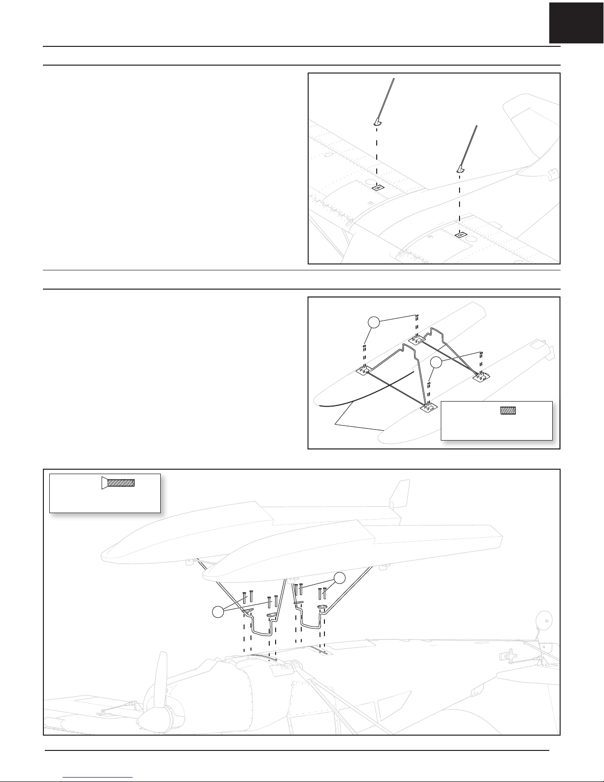
B
B
3 x 16mm
Tapered hex head machine
B
Scale Accessories Optional
Float Installation Optional
Install the non-functional scale antennas on the top of the wing. Insert the tab into
the slot in the plastic fi tting and slide it toward the tail to lock the antenna in place.
Float Assembly
The water rudder is mounted on the left fl oat. When the two fl oats are arranged
correctly, the chine rails on the edges of the fl oats from the step to the nose
should be on the insides of the fl oats.
1. Install the two cross members and the front and rear fl oat struts between the
left and right fl oats as shown.
2. Secure the assembly together using eight 3mm set screws (A).
Float Installation
1. Insert the struts into the fl oat slots on the bottom of the fuselage.
2. Secure the front and rear struts to the fuselage using the included brackets
and eight 3 x 16mm screws screws (B).
3. Connect the fl oat servo lead to the rudder extension in the fuselage. Secure the
servo wire to the rear strut with tape or zip ties.
Disassemble in reverse order.
A
A
3mm
Set screw
A
Chine
Rails
7
www.modellmarkt24.ch; www.modellmarkt24.de
Page 8
www.modellmarkt24.ch; www.modellmarkt24.de
EN
C
D
8
Maule M7
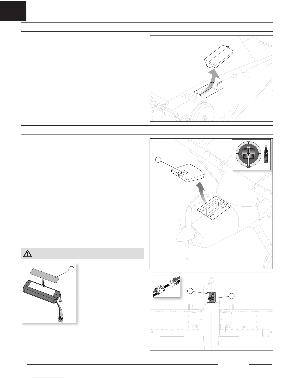
Battery Installation and ESC Arming
Receiver Access
Battery Selection
The E-fl ite® 2200mAh 11.1V 3S 30C Li-Po battery (EFLB22003S30) is
recommended. Refer to the Optional Parts List for other recommended
batteries. If using a battery other than those listed, the battery should be within the
range of capacity, dimensions and weight of the E-fl ite Li-Po battery pack. Be sure
the model balances at the recommended CG before fl ying.
1. Lower the throttle and throttle trim to the lowest settings. Power on the
transmitter, then wait fi ve seconds.
2. Slide the hatch latch (A) toward the tail and lift the hatch to remove.
3. For added security, apply the loop side (soft side) of the optional hook and
loop tape (B) to the bottom of the battery and the hook side to the
battery tray.
4. Install the fully charged battery (C) in toward the front of the battery
compartment, as shown. Secure using the hook and loop strap (D).
5. Connect the battery to the ESC (the ESC is now armed).
6. Keep the aircraft immobile, away from wind, upright and on a fl at surface
until the system initializes.
• The ESC will produce a series of sounds. Three fl at tones followed
immediately by two ascending tones.
• An LED will light on the receiver.
7. Slide the hatch latch (A), reinstall the hatch, and release the latch.
The receiver for the Maule M7 is located inside the fuselage below the cockpit. Slide the
hatch latch toward the tail and remove the bottom hatch to gain access to the receiver.
A
CAUTION: Always keep hands away from the propeller. When armed, the
motor will turn the propeller in response to any throttle movement.
B
Optional
www.modellmarkt24.ch; www.modellmarkt24.de
Page 9

www.modellmarkt24.ch; www.modellmarkt24.de
EN
9
Switching OFF SAFE Select Binding Sequence
Install Bind Plug
RX in Bind Mode
Bind TX to RX
Remove Bind Plug
Install Bind Plug
Remove Bind Plug
RX in Bind Mode
Bind TX to RX
This product requires an approved Spektrum
™
DSM2®/DSMX® compatible
transmitter. Visit www.bindnfl y.com for a complete list of approved
transmitters.
The aircraft has an optional SAFE Select feature, which can be switched ON or
OFF easily by binding in a specifi c manner as described below.
IMPORTANT: Before binding a transmitter, read the Transmitter Setup section of this
manual to ensure that your transmitter is properly programmed for this aircraft.
Transmitter and Receiver Binding / Switching ON and OFF SAFE Select
Bind Plug Installation
BIND PLUG
Binding Procedure / Switching OFF SAFE Select
IMPORTANT: The included AR636 receiver has been programmed for
operation specifi cally for this aircraft. Refer to the receiver manual for
correct setup if the receiver is replaced or is used in another aircraft.
CAUTION: When using a Futaba® transmitter with a Spektrum DSM
module, you must reverse the throttle channel and rebind. Refer to your
Spektrum module manual for binding and failsafe instructions. Refer to your
Futaba transmitter manual for instructions on reversing the throttle channel.
1. Make sure the transmitter is powered off.
2. Move the transmitter controls to neutral (fl ight controls: rudder, elevators
and ailerons) or to low positions (throttle, throttle trim). *
3. Install a bind plug in the receiver bind port.
4. Place the aircraft level on its wheels, then connect the fl ight battery
to the ESC. The ESC will produce a series of sounds. Three fl at tones
followed immediately by two ascending tones confi rm that the LVC is set
correctly for the ESC.
The orange bind LED on the receiver will begin to fl ash rapidly. DO
NOT remove the bind plug at this time.
5. Take three steps away from the aircraft /receiver and then power ON the
transmitter while holding the transmitter bind button or switch. Refer to
your transmitter’s manual for specifi c binding instructions.
IMPORTANT: Do not to point the transmitter’s antenna directly at the
receiver while binding.
IMPORTANT: Keep away from large metal objects while binding.
6. The receiver is bound to the transmitter when the orange bind light on the receiver
stays orange. The ESC will produce a series of sounds. Three fl at tones followed
immediately by two ascending tones. The tones indicate the ESC is armed,
provided the throttle stick and throttle trim are low enough to trigger arming.
7. Remove the bind plug from the bind port.
IMPORTANT: Once bound, the receiver will retain its bind settings for that
transmitter until it has been intentionally changed, even when power is
cycled ON and OFF. Repeat the binding process as necessary.
SAFE Select OFF Indication
Every time the receiver is powered ON the surfaces will cycle back and forth
once to indicate that SAFE Select has been switched OFF.
The throttle will not arm if the transmitter’s throttle control is not put at the
lowest position. If problems are encountered, follow the binding instructions
and refer to the transmitter troubleshooting guide for other instructions. If
needed, contact the appropriate Horizon Product Support offi ce.
Binding Procedure / Switching ON SAFE Select
IMPORTANT: The included AR636 receiver has been programmed for
operation specifi cally for this aircraft. Refer to the receiver manual for
correct setup if the receiver is replaced or is used in another aircraft.
CAUTION: When using a Futaba® transmitter with a Spektrum DSM
module, you must reverse the throttle channel and rebind. Refer to your
Spektrum module manual for binding and failsafe instructions. Refer to your
Futaba transmitter manual for instructions on reversing the throttle channel.
1. Make sure the transmitter is powered off.
2. Move the transmitter controls to neutral (fl ight controls: rudder, elevators
and ailerons) or to low positions (throttle, throttle trim).*
3. Install a bind plug in the receiver bind port.
4. Place the aircraft level on its wheels, then connect the fl ight battery to the ESC. The
ESC will produce a series of sounds. Three fl at tones followed immediately by two
ascending tones confi rm that the LVC is set correctly for the ESC. The orange bind
LED on the receiver will begin to fl ash rapidly.
5. Remove the bind plug from the bind port.
6. Take three steps away from the aircraft /receiver and then power ON the
transmitter while holding the transmitter bind button or switch. Refer to
your transmitter’s manual for specifi c binding instructions.
IMPORTANT: Do not to point the transmitter’s antenna directly at the
receiver while binding.
IMPORTANT: Keep away from large metal objects while binding.
7. The receiver is bound to the transmitter when the orange bind light on the receiver
stays orange. The ESC will produce a series of sounds. Three fl at tones followed
immediately by two ascending tones. The tones indicate the ESC is armed,
provided the throttle stick and throttle trim are low enough to trigger arming.
IMPORTANT: Once bound, the receiver will retain its bind settings for that
transmitter until it has been intentionally changed, even when power is
cycled ON and OFF. Repeat the binding process as necessary.
SAFE Select ON Indication
Every time the receiver is powered ON the surfaces will cycle back and forth twice
with a slight pause at neutral position to indicate that SAFE Select is switched ON.
The throttle will not arm if the transmitter’s throttle control is not put at the
lowest position. If problems are encountered, follow the binding instructions
and refer to the transmitter troubleshooting guide for other instructions. If
needed, contact the appropriate Horizon Product Support offi ce.
* Failsafe
If the receiver loses transmitter communication, the failsafe will activate. When activated, failsafe moves the throttle channel to its preset
failsafe position (low throttle) that was set during binding. All other channels move to actively level the aircraft in fl ight.
Switching ON SAFE Select Binding Sequence
www.modellmarkt24.ch; www.modellmarkt24.de
Page 10

www.modellmarkt24.ch; www.modellmarkt24.de
EN
10
Maule M7
55 – 70mm +/- 3mm
Control Horn and Servo Arm Settings
The table to the right shows the factory settings for the control horns and servo
arms. Fly the aircraft at factory settings before making changes.
NOTICE: If control throws are changed from the factory settings, the AR636
gain values may need to be adjusted. Refer to the Spektrum AR636 manual
for adjustment of gain values.
After fl ying, adjust the linkage positions for the desired control response if
necessary. See the table to the below:
SAFE® Select Switch Designation
SAFE® Select technology can be easily assigned to any open switch (two or
three position) on the transmitter. With this new feature, you now have the fl exibility to enable or disable the technology while in fl ight.
IMPORTANT: Before assigning your desired switch, ensure that the travel for
that channel is set at 100% in both direction.
Assigning a switch
1. Bind the aircraft correctly to activate SAFE Select. This will allow the
system to be assigned to a switch.
2. Hold both transmitter sticks to the inside bottom corners and toggle the
desired switch fi ve times (one toggle = full up and down) to assign that
switch. The control surfaces of the aircraft will move, indicating the switch
has been selected.
Repeat the process to assign a different switch if desired.
TIP: SAFE Select is assignable on any unused Channels 5–9
Mode 1 and 2 Transmitters
Factory Settings Horns Arms
Elevator
Rudder
Ailerons
Flaps
Center of Gravity (CG)
The CG location is measured from the leading edge of the wing. This
CG location has been determined with the recommended Li-Po battery
(EFLB22003S300) mounted all the way forward.
Begin with the battery all the way to the rear of the battery compartment when
running a battery larger than a 3S 2200mAh. Always confi rm the CG is located
correctly when changing the battery confi guration.
Back from the leading edge
of the wing at the fuselage.
two or three position switch
x 5
100%
100%
Tuning Horns Arms
More control throw
Less control throw
www.modellmarkt24.ch; www.modellmarkt24.de
Page 11

www.modellmarkt24.ch; www.modellmarkt24.de
EN
11
AS3X Control Direction Test
This test ensures that the AS3X® control system is functioning properly.
Assemble the aircraft and bind your transmitter to the receiver before
performing this test.
1. Raise the throttle just above 25%, then lower the throttle to activate
AS3X technology.
CAUTION: Keep all body parts, hair and loose clothing away from a
moving propeller, as these items could become entangled.
2. Move the entire aircraft as shown and ensure the control surfaces move in
the direction indicated in the graphic. If the control surfaces do not respond as
shown, do not fl y the aircraft. Refer to the receiver manual for more information.
Once the AS3X system is active, control surfaces may move rapidly. This is
normal. AS3X remains active until the battery is disconnected.
Aircraft movement AS3X Reaction
ElevatorAileronRudder
During the fi rst fl ight, trim the aircraft for level fl ight at 3/4 throttle with fl aps
up. Make small trim adjustments with the transmitter’s trim switches to
straighten the aircraft’s fl ight path.
After adjusting the trim, do not touch the control sticks for three seconds. This
allows the receiver to learn the correct settings to optimize AS3X performance.
Failure to do so could affect fl ight performance.
In Flight Trimming
3 Seconds
www.modellmarkt24.ch; www.modellmarkt24.de
Page 12
www.modellmarkt24.ch; www.modellmarkt24.de
EN
12
Maule M7
Flying Tips and Repairs
Consult local laws and ordinances before choosing a fl ying location.
Range Check your Radio System
Before you fl y, range check the radio system. Refer to your specifi c transmitter
instruction manual for range test information.
Oscillation
Once the AS3X system is active (after advancing the throttle for the fi rst time),
the control surfaces will react to aircraft movement. In some fl ight conditions
oscillation may occur (the aircraft rocks back and forth on one axis due to
overcontrol). If oscillation occurs, refer to the Troubleshooting Guide for more
information.
Takeoff
Place the aircraft facing into the wind. Set the transmitter in low rate and use the
fl ap switch to drop the fl aps to takeoff or “half” position. Flaps make takeoffs
shorter. Gradually increase the throttle to ¾ and steer with the rudder. As the tail
comes off the ground, pull back gently on the elevator. When airborne, climb to a
comfortable altitude and then fl ip the fl ap switch to level the fl aps.
Flying
With the recommended battery pack (EFLB22003S30) set the transmitter timer
or a stopwatch to fi ve minutes. After fi ve minutes, land the aircraft. Adjust the
timer for longer or shorter fl ights once you have fl own the model. If at any time
the motor power reduces, land the aircraft immediately to recharge the fl ight
battery. See the Low Voltage Cutoff (LVC) section for more details on maximizing
battery health and run time.
Landing
Land the aircraft into the wind. Use a small amount of throttle for the entire
descent. Lower the throttle to ¼ and fl ip the fl ap switch to deploy the fl aps to
the landing or “full down” position. Flaps will make the landing approach
steeper and slower, and allow for a smoother landing.
Keep the throttle on until the aircraft is ready to fl are. During fl are, keep the
wings level and the aircraft pointed into the wind. Gently lower the throttle
while pulling back on the elevator to bring the aircraft down on its wheels.
If landing on grass, hold full up elevator after touchdown and when taxiing to
prevent nosing over.
Once on the ground, avoid sharp turns until the plane has slowed enough to
prevent scraping the wingtips.
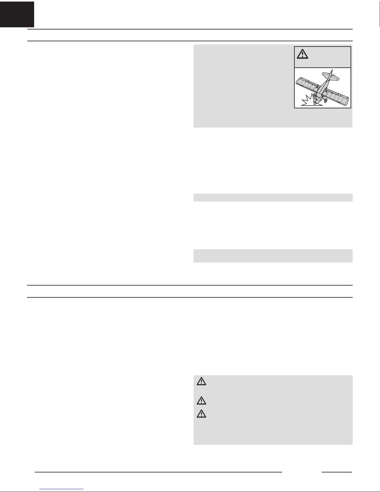
NOTICE: If a crash is imminent, reduce the throttle
and trim fully. Failure to do so could result in extra
damage to the airframe, as well as damage to the
ESC and motor.
NOTICE: After any impact, always ensure the
receiver is secure in the fuselage. If the receiver
is replaced, install the new receiver in the same
orientation as the original receiver or damage
may result.
NOTICE: Crash damage is not covered under
warranty.
NOTICE: When done fl ying, never leave the aircraft in direct sunlight or in a hot,
enclosed area such as a car. Doing so can damage the aircraft.
Low Voltage Cutoff (LVC)
When a Li-Po battery is discharged below 3V per cell, it will not hold a charge.
The ESC protects the fl ight battery from over-discharge using Low Voltage
Cutoff (LVC). Before the battery charge decreases too much, LVC removes
power supplied to the motor. Power to the motor reduces, showing that some
battery power is reserved for fl ight control and safe landing.
Disconnect and remove the Li-Po battery from the aircraft after use to prevent
trickle discharge. Charge your Li-Po battery to about half capacity before
storage. During storage, make sure the battery charge does not fall below 3V
per cell. LVC does not prevent the battery from over-discharge during storage.
NOTICE: Repeated fl ying to LVC will damage the battery.
Tip: Monitor your aircraft battery’s voltage before and after fl ying by using a
Li-Po Cell Voltage Checker (EFLA111, sold separately).
Repairs
Thanks to the foam material in this aircraft, repairs to the foam can be made using
virtually any adhesive (hot glue, regular CA, epoxy, etc). When parts are not repairable,
see the Replacement Parts List for ordering by item number. For a listing of all
replacement and optional parts, refer to the list at the end of this manual.
NOTICE: Use of CA accelerant on your aircraft can damage paint. DO NOT
handle the aircraft until accelerant fully dries.
WARNING: Always
decrease throttle
at propeller strike.
Flying off water poses a higher risk because piloting errors or water conditions
can cause the aircraft to become stranded. Only fl y from the water when a level
of comfort has been achieved fl ying the aircraft from the ground. Never fl y near
people fi shing, swimming, or playing.
Pre-Flight
Ensure the optional fl oats are secure on the fuselage and the water rudder is correctly
connected and operating with the main rudder before putting the aircraft in the water.
Select an area to fl y that does not have water currents, salt water, or debris. Look around
the fl ight area and be aware of trees, docks, buoys, or other obstacles. Always fl y with a
spotter and avoid swimmers, boaters, people fi shing, and people on the beach.
Taxiing
When taxiing, use low throttle settings and the rudder to steer. Hold up elevator
to help keep the rudder in the water and the nose of the fl oats above the
surface. Steer into the wind when turning, and crab into the wind if crosswind
taxiing is required. When turning or crabbing into the wind, apply aileron
against the wind to keep the upwind side of the wing down and prevent the
aircraft from being fl ipped over. Do not apply down elevator when the airplane
is taxiing or during the takeoff run.
On Step
When speed increases with throttle, the fl oats will rise out of the water and begin
to plane on the surface of the water, riding “on step.” The fl oats will come on step
at a speed below fl ight speed, this is a transitional phase when the aircraft is not
up to fl ight speed yet. This is considered a high speed taxi. Do not attempt to take
off as soon as the aircraft comes on step. Use low to medium throttle and hold up
elevator to manage speed on the water during a high speed taxi.
Takeoff
To lift off from the water, set the fl aps to the takeoff position, hold up elevator and
accelerate the aircraft to bring it on step. Relax the up elevator as the airplane comes
on step and accelerate to fl ight speed with full throttle. When the aircraft is travelling
at a suffi cient speed, pull back slightly on the elevator to rotate for liftoff.
Landing
To land on the water, set the fl aps to the landing position, and fl y into the wind.
Reduce the throttle to a low setting but keep some power during the approach.
As the aircraft settles into ground effect, reduce the throttle fully and hold up
elevator to fl are. Hold up elevator through the touch down and as the airplane
decelerates on the water.
WARNING: Never attempt to retrieve a downed aircraft by swimming
unless you are suffi ciently trained and/or there is another person
available to respond in the case of an emergency.
CAUTION: Have a plan for retrieval in the event the airplane becomes
stranded. Never retrieve a downed model in the water alone.
CAUTION: If at any time water splashes in the fuselage while fl ying
from water, bring the airplane to shore, open the battery hatch and
immediately remove any water that may have gotten in the fuselage. Leave the
battery hatch open overnight to let the inside dry out and to prevent moisture
damage to the electronic components. Failure to do so could cause the
electronic components to fail, which could result in a crash.
TIP: Use a fi shing pole with heavy line as a retrieval tool. Attach a tennis ball to
the line, and throw the ball past a stranded aircraft to retrieve it.
Flying Off Water
www.modellmarkt24.ch; www.modellmarkt24.de
Page 13

www.modellmarkt24.ch; www.modellmarkt24.de
EN
Motor Service
CAUTION: Always disconnect the fl ight battery before performing
motor service.
1. Remove the spinner screw (A) and the spinner.
2. Use a tool to remove the propeller nut and then remove the propeller,
spinner backplate and prop adaptor from the motor shaft.
3. Remove the four screws (B) and the motor with the X-mount from the
fuselage.
4. Disconnect the motor wires from the ESC wires.
5. Remove the four screws (C) and motor from the X-mount.
6. Assemble in reverse order.
• Correctly align and connect the motor wire colors with the ESC wires.
• Install the propeller with the paint facing out from the motor.
• Tighten the spinner screw to secure the propeller into place.
C D
3 x 6mm Tapered
hex head machine
2.5 x 8mm machine
3 x 12mm Tapered
phillips self tapping
B
3 x 20mm Tapered
hex head machine
A
A
B
Wiring not shown
C
D
13
PNP Receiver Selection and Installation
The Spektrum AR636 receiver is recommended for this airplane. Other receiver
selections should be at least 6-channels and offer full range. Refer to the receiver
manual for correct installation and operation instructions.
CAUTION: When using a Futaba® transmitter with a Spektrum DSM
module, you must reverse the throttle channel and rebind. Refer to the
Spektrum module manual for binding and failsafe instructions. Refer to the
Futaba transmitter manual for instructions on reversing the throttle channel. All
fl ight surfaces must also be checked for the correct direction.
Installation (AR636 shown)
1. Remove the hatch from the bottom of the fuselage.
2. Mount the receiver parallel to the length of the fuselage as shown. Use
double-sided servo tape.
3. Plug the appropriate control surfaces into the their respective ports on the receiver.
CAUTION: Incorrect installation of the receiver could cause a crash.
AR636 Port
Assignments
BND/PRG = BIND
1 = Throttle
2 = Aileron
3 = Elevator
4 = Rudder
5 = Lights
6 = Flaps
Post Flight
1. Disconnect the fl ight battery from the ESC (Required for Safety and battery life).
2. Power OFF the transmitter.
3. Remove the fl ight battery from the aircraft.
4. Recharge the fl ight battery.
5. Repair or replace all damaged parts.
6. Store the fl ight battery apart from the aircraft and monitor the battery charge.
7. Make note of the fl ight conditions and fl ight plan results, planning for future fl ights.
www.modellmarkt24.ch; www.modellmarkt24.de
Page 14
www.modellmarkt24.ch; www.modellmarkt24.de
EN
14
Maule M7
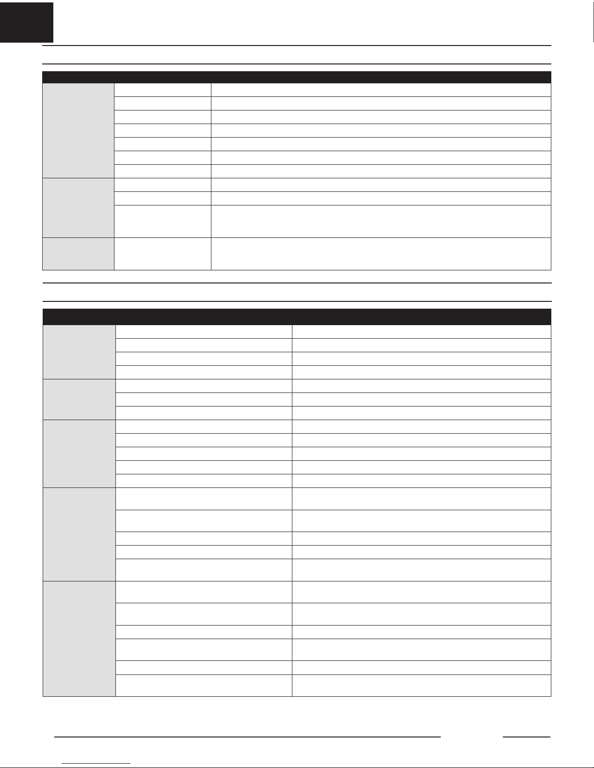
Troubleshooting Guide AS3X
Problem Possible Cause Solution
Oscillation
Damaged propeller or spinner Replace propeller or spinner
Imbalanced propeller Balance the propeller
Motor vibration Replace parts or correctly align all parts and tighten fasteners as needed
Loose receiver Align and secure receiver in fuselage
Loose aircraft controls Tighten or otherwise secure parts (servo, arm, linkage, horn and control surface)
Worn parts Replace worn parts (especially propeller, spinner or servo)
Irregular servo movement Replace servo
Inconsistent fl ight
performance
Trim is not at neutral If you adjust trim more than 8 clicks, adjust the clevis to remove trim
Sub-Trim is not at neutral No Sub-Trim is allowed. Adjust the servo linkage
Aircraft was not kept
immobile for 5 seconds
after battery connection
With the throttle stick in lowest position. Disconnect battery, then reconnect battery and keep the aircraft
still for fi ve seconds
Incorrect response
to the AS3X Control
Direction Test
Incorrect direction settings
in the receiver, which can
cause a crash
DO NOT fl y. Correct the direction settings (refer to the receiver manual), then fl y
Problem Possible Cause Solution
Aircraft will not respond
to throttle but responds
to other controls
Throttle not at idle and/or throttle trim too high Reset controls with throttle stick and throttle trim at lowest setting
Throttle servo travel is lower than 100% Make sure throttle servo travel is 100% or greater
Throttle channel is reversed Reverse throttle channel on transmitter
Motor disconnected from ESC Make sure motor is connected to the ESC
Extra propeller noise
or extra vibration
Damaged propeller and spinner, collet or motor Replace damaged parts
Propeller is out of balance Balance or replace propeller
Prop nut is too loose Tighten the prop nut
Reduced fl ight time or
aircraft underpowered
Flight battery charge is low Completely recharge fl ight battery
Propeller installed backwards Install propeller with numbers facing forward
Flight battery damaged Replace fl ight battery and follow fl ight battery instructions
Flight conditions may be too cold Make sure battery is warm before use
Battery capacity too low for flight conditions Replace battery or use a larger capacity battery
Aircraft will not Bind
(during binding) to
transmitter
Transmitter too near aircraft during binding process
Move powered transmitter a few feet from aircraft, disconnect and reconnect
fl ight battery to aircraft
Aircraft or transmitter is too close to large metal
object, wireless source or another transmitter
Move aircraft and transmitter to another location and attempt binding again
The bind plug is not installed correctly in the bind port Install bind plug in bind port and bind the aircraft to the transmitter
Flight battery/transmitter battery charge is too low Replace/recharge batteries
Bind switch or button not held long enough during
bind process
Power off transmitter and repeat bind process. Hold transmitter bind
button or switch until receiver is bound
Aircraft will not
connect (after
binding) to
transmitter
Transmitter too near aircraft during connecting process
Move powered transmitter a few feet from aircraft, disconnect and reconnect
fl ight battery to aircraft
Aircraft or transmitter is too close to large metal
object, wireless source or another transmitter
Move aircraft and transmitter to another location and attempt connecting again
Bind plug left installed in bind port Rebind transmitter to the aircraft and remove the bind plug before cycling power
Aircraft bound to different model memory
(ModelMatch
TM
radios only)
Select correct model memory on transmitter
Flight battery/Transmitter battery charge is too low Replace/recharge batteries
Transmitter may have been bound to a different aircraft using different DSM protocol
Bind aircraft to transmitter
Troubleshooting Guide
www.modellmarkt24.ch; www.modellmarkt24.de
Page 15

www.modellmarkt24.ch; www.modellmarkt24.de
EN
15
Troubleshooting Guide (Continued)
Problem Possible Cause Solution
Control surface does
not move
Control surface, control horn, linkage or servo damage Replace or repair damaged parts and adjust controls
Wire damaged or connections loose Do a check of wires and connections, connect or replace as needed
Transmitter is not bound correctly or the incorrect
airplanes was selected
Re-bind or select correct airplanes in transmitter
Flight battery charge is low Fully recharge fl ight battery
BEC (Battery Elimination Circuit) of the ESC is damaged Replace ESC
Controls reversed Transmitter settings are reversed
Perform the Control Direction Test and adjust the controls on transmitter appropriately
Motor power pulses
then motor loses power
ESC uses default soft Low Voltage Cutoff (LVC) Recharge fl ight battery or replace battery that is no longer performing
Weather conditions might be too cold Postpone flight until weather is warmer
Battery is old, worn out, or damaged Replace battery
Battery C rating might be too low Use recommended battery
AMA National Model Aircraft Safety Code
Effective January 1, 2014
A. GENERAL
A model aircraft is a non-human-carrying aircraft capable of sustained fl ight in the
atmosphere. It may not exceed limitations of this code and is intended exclusively for
sport, recreation, education and/or competition. All model fl ights must be conducted in
accordance with this safety code and any additional rules specifi c to the fl ying site.
1. Model aircraft will not be fl own:
a. In a careless or reckless manner.
b. At a location where model aircraft activities are prohibited.
3. Model aircraft pilots will:
a. Yield the right of way to all man carrying aircraft.
b. See and avoid all aircraft and a spotter must be used when appropriate
(AMA Document #540-D.)
c. Not fl y higher than approximately 400 feet above ground level within three
(3) miles of an airport, without notifying the airport operator.
d. Not interfere with operations and traffi c patterns at any airport, heliport or
seaplane base except where there is a mixed use agreement.
e. Not exceed a takeoff weight, including fuel, of 55 pounds unless in compliance
with the AMA Large Model Aircraft program. (AMA Document 520-A.)
f. Ensure the aircraft is identifi ed with the name and address or AMA
number of the owner on the inside or affi xed to the outside of the model
aircraft. (This does not apply to model aircraft fl own indoors).
g. Not operate aircraft with metal-blade propellers or with gaseous boosts
except for helicopters operated under the provisions of AMA Document #555.
h. Not operate model aircraft while under the infl uence of alcohol or while using any
drug which could adversely affect the pilot’s ability to safely control the model.
i. Not operate model aircraft carrying pyrotechnic devices which explode
or burn, or any device which propels a projectile or drops any object that
creates a hazard to persons or property.
Exceptions:
• Free Flight fuses or devices that burn producing smoke and are
securely attached to the model aircraft during fl ight.
• Rocket motors (using solid propellant) up to a G-series size may be
used provided they remain attached to the model during fl ight. Model
rockets may be fl own in accordance with the National Model Rocketry
Safety Code but may not be launched from model aircraft.
• Offi cially designated AMA Air Show Teams (AST) are authorized to
use devices and practices as defi ned within the Team AMA Program
Document (AMA Document #718).
j. Not operate a turbine-powered aircraft, unless in compliance with the
AMA turbine regulations. (AMA Document #510-A).
3. Model aircraft will not be fl own in AMA sanctioned events, air shows or
model demonstrations unless:
a. The aircraft, control system and pilot skills have successfully demonstrated
all maneuvers intended or anticipated prior to the specifi c event.
b. An inexperienced pilot is assisted by an experienced pilot.
4. When and where required by rule, helmets must be properly worn and
fastened. They must be OSHA, DOT, ANSI, SNELL or NOCSAE approved or
comply with comparable standards.
B. RADIO CONTROL
1. All pilots shall avoid fl ying directly over unprotected people, vessels, vehicles
or structures and shall avoid endangerment of life and property of others
2. A successful radio equipment ground-range check in accordance with
manufacturer’s recommendations will be completed before the fi rst fl ight of
a new or repaired model aircraft.
3. At all fl ying sites a safety line(s) must be established in front of which all
fl ying takes place (AMA Document #706.)
a. Only personnel associated with fl ying the model aircraft are allowed at or
in front of the safety line.
b. At air shows or demonstrations, a straight safety line must be established.
c. An area away from the safety line must be maintained for spectators.
d. Intentional fl ying behind the safety line is prohibited.
4. RC model aircraft must use the radio-control frequencies currently allowed
by the Federal Communications Commission (FCC). Only individuals properly
licensed by the FCC are authorized to operate equipment on Amateur Band
frequencies.
5. RC model aircraft will not operate within three (3) miles of any pre-existing
fl ying site without a frequency-management agreement (AMA Documents
#922 and #923.)
6. With the exception of events fl own under offi cial AMA Competition
Regulations, excluding takeoff and landing, no powered model may be fl own
outdoors closer than 25 feet to any individual, except for the pilot and the
pilot’s helper(s) located at the fl ight line.
7. Under no circumstances may a pilot or other person touch a model aircraft
in fl ight while it is still under power, except to divert it from striking an
individual.
8. RC night fl ying requires a lighting system providing the pilot with a
clear view of the model’s attitude and orientation at all times. Hand-held
illumination systems are inadequate for night fl ying operations.
9. The pilot of a RC model aircraft shall:
a. Maintain control during the entire fl ight, maintaining visual contact
without enhancement other than by corrective lenses prescribed for the
pilot.
b. Fly using the assistance of a camera or First-Person View (FPV) only in
accordance with the procedures outlined in AMA Document #550.
c. Fly using the assistance of autopilot or stabilization system only in
accordance with the procedures outlined in AMA Document #560.
Please see your local or regional modeling association’s guidelines for proper,
safe operation of your model aircraft.
www.modellmarkt24.ch; www.modellmarkt24.de
Page 16

www.modellmarkt24.ch; www.modellmarkt24.de
EN
16
Maule M7
Limited Warranty
What this Warranty Covers
Horizon Hobby, LLC, (Horizon) warrants to the original purchaser that the
product purchased (the “Product”) will be free from defects in materials and
workmanship at the date of purchase.
What is Not Covered
This warranty is not transferable and does not cover (i) cosmetic damage, (ii)
damage due to acts of God, accident, misuse, abuse, negligence, commercial
use, or due to improper use, installation, operation or maintenance, (iii)
modifi cation of or to any part of the Product, (iv) attempted service by
anyone other than a Horizon Hobby authorized service center, (v) Product not
purchased from an authorized Horizon dealer, or (vi) Product not compliant
with applicable technical regulations, or (vii) use that violates any applicable
laws, rules, or regulations.
OTHER THAN THE EXPRESS WARRANTY ABOVE, HORIZON MAKES NO OTHER
WARRANTY OR REPRESENTATION, AND HEREBY DISCLAIMS ANY AND ALL
IMPLIED WARRANTIES, INCLUDING, WITHOUT LIMITATION, THE IMPLIED
WARRANTIES OF NON-INFRINGEMENT, MERCHANTABILITY AND FITNESS
FOR A PARTICULAR PURPOSE. THE PURCHASER ACKNOWLEDGES THAT THEY
ALONE HAVE DETERMINED THAT THE PRODUCT WILL SUITABLY MEET THE
REQUIREMENTS OF THE PURCHASER’S INTENDED USE.
Purchaser’s Remedy
Horizon’s sole obligation and purchaser’s sole and exclusive remedy shall be
that Horizon will, at its option, either (i) service, or (ii) replace, any Product
determined by Horizon to be defective. Horizon reserves the right to inspect
any and all Product(s) involved in a warranty claim. Service or replacement
decisions are at the sole discretion of Horizon. Proof of purchase is required
for all warranty claims. SERVICE OR REPLACEMENT AS PROVIDED UNDER THIS
WARRANTY IS THE PURCHASER’S SOLE AND EXCLUSIVE REMEDY.
Limitation of Liability
HORIZON SHALL NOT BE LIABLE FOR SPECIAL, INDIRECT, INCIDENTAL
OR CONSEQUENTIAL DAMAGES, LOSS OF PROFITS OR PRODUCTION OR
COMMERCIAL LOSS IN ANY WAY, REGARDLESS OF WHETHER SUCH CLAIM
IS BASED IN CONTRACT, WARRANTY, TORT, NEGLIGENCE, STRICT LIABILITY
OR ANY OTHER THEORY OF LIABILITY, EVEN IF HORIZON HAS BEEN ADVISED
OF THE POSSIBILITY OF SUCH DAMAGES. Further, in no event shall the
liability of Horizon exceed the individual price of the Product on which
liability is asserted. As Horizon has no control over use, setup, fi nal assembly,
modifi cation or misuse, no liability shall be assumed nor accepted for any
resulting damage or injury. By the act of use, setup or assembly, the user
accepts all resulting liability. If you as the purchaser or user are not prepared
to accept the liability associated with the use of the Product, purchaser is
advised to return the Product immediately in new and unused condition to the
place of purchase.
Law
These terms are governed by Illinois law (without regard to confl ict of law
principals). This warranty gives you specifi c legal rights, and you may also
have other rights which vary from state to state. Horizon reserves the right to
change or modify this warranty at any time without notice.
WARRANTY SERVICES
Questions, Assistance, and Services
Your local hobby store and/or place of purchase cannot provide warranty
support or service. Once assembly, setup or use of the Product has been
started, you must contact your local distributor or Horizon directly. This will
enable Horizon to better answer your questions and service you in the event
that you may need any assistance. For questions or assistance, please visit
our website at www.horizonhobby.com, submit a Product Support Inquiry, or
call the toll free telephone number referenced in the Warranty and Service
Contact Information section to speak with a Product Support representative.
Inspection or Services
If this Product needs to be inspected or serviced and is compliant in the
country you live and use the Product in, please use the Horizon Online Service
Request submission process found on our website or call Horizon to obtain a
Return Merchandise Authorization (RMA) number. Pack the Product securely
using a shipping carton. Please note that original boxes may be included,
but are not designed to withstand the rigors of shipping without additional
protection. Ship via a carrier that provides tracking and insurance for lost or
damaged parcels, as Horizon is not responsible for merchandise until it arrives
and is accepted at our facility. An Online Service Request is available at http://
www.horizonhobby.com/content/_service-center_render-service-center. If you
do not have internet access, please contact Horizon Product Support to obtain
a RMA number along with instructions for submitting your product for service.
When calling Horizon, you will be asked to provide your complete name,
street address, email address and phone number where you can be reached
during business hours. When sending product into Horizon, please include
your RMA number, a list of the included items, and a brief summary of the
problem. A copy of your original sales receipt must be included for warranty
consideration. Be sure your name, address, and RMA number are clearly
written on the outside of the shipping carton.
NOTICE: Do not ship LiPo batteries to Horizon. If you have any issue with
a LiPo battery, please contact the appropriate Horizon Product Support
offi ce.
Warranty Requirements
For Warranty consideration, you must include your original sales receipt
verifying the proof-of-purchase date. Provided warranty conditions have
been met, your Product will be serviced or replaced free of charge. Service or
replacement decisions are at the sole discretion of Horizon.
Non-Warranty Service
Should your service not be covered by warranty, service will be
completed and payment will be required without notifi cation or estimate
of the expense unless the expense exceeds 50% of the retail purchase
cost. By submitting the item for service you are agreeing to payment of the
service without notifi cation. Service estimates are available upon request. You
must include this request with your item submitted for service. Non-warranty
service estimates will be billed a minimum of ½ hour of labor. In addition you
will be billed for return freight. Horizon accepts money orders and cashier’s
checks, as well as Visa, MasterCard, American Express, and Discover cards.
By submitting any item to Horizon for service, you are agreeing to Horizon’s
Terms and Conditions found on our website http://www.horizonhobby.com/
content/_service-center_render-service-center.
ATTENTION: Horizon service is limited to Product compliant in the
country of use and ownership. If received, a non-compliant Product will
not be serviced. Further, the sender will be responsible for arranging
return shipment of the un-serviced Product, through a carrier of the
sender’s choice and at the sender’s expense. Horizon will hold noncompliant Product for a period of 60 days from notifi cation, after which
it will be discarded.
10/15
Contact Information
Country of Purchase Horizon Hobby Contact Information Address
United States
of America
Horizon Service Center
(Repairs and Repair Requests)
servicecenter.horizonhobby.com/
RequestForm/
4105 Fieldstone Rd
Champaign, Illinois, 61822 USA
Horizon Product Support
(Product Technical Assistance)
productsupport@horizonhobby.com
877-504-0233
Sales
websales@horizonhobby.com
800-338-4639
European Union
Horizon Technischer Service service@horizonhobby.eu
Hanskampring 9
D 22885 Barsbüttel, Germany
Sales: Horizon Hobby GmbH +49 (0) 4121 2655 100
www.modellmarkt24.ch; www.modellmarkt24.de
Page 17

www.modellmarkt24.ch; www.modellmarkt24.de
EN
17
FCC ID: BRWDASRX15
This equipment has been tested and found to comply with the limits for Part 15 of the FCC rules. These limits are designed to provide reasonable protection against
harmful interference in a residential installation. This equipment generates uses and can radiate radio frequency energy and, if not installed and used in accordance
with the instructions, may cause harmful interference to radio communications.
However, there is no guarantee that interference will not occur in a particular installation. If this equipment does cause harmful interference to radio or television
reception, which can be determined by turning the equipment off and on, the user is encouraged to try to correct the interference by one or more of the following
measures:
• Reorient or relocate the receiving antenna.
• Increase the separation between the equipment and receiver.
• Connect the equipment to an outlet on a circuit different from that to which the receiver is connected.
This device complies with part 15 of the FCC rules. Operation is subject to the following two conditions: (1) This device may not cause harmful interference, and
(2) this device must accept any interference received, including interference that may cause undesired operation.
NOTICE: Modifi cations to this product will void the user’s authority to operate this equipment.
FCC Information
IC Information
IC: 6157A-AMRX15
This device complies with Industry Canada licence-exempt RSS standard(s). Operation is subject to the following two conditions: (1) this device may not cause
interference, and (2) this device must accept any interference, including interference that may cause undesired operation of the device.”
Compliance Information for the European Union
EU Compliance Statement:
EFL5375 MAULE 1.5M PNP; Horizon Hobby, LLC hereby declares that this product is in compliance with the essential requirements and other relevant
provisions of the EMC Directive.
EFL5350 MAULE 1.5M BNF BASIC; Horizon Hobby, LLC hereby declares that this product is in compliance with the essential requirements and other relevant
provisions of the RED and EMC Directives.
A copy of the EU Declaration of Conformity is available online at: http://www.horizonhobby.com/content/support-render-compliance.
Instructions for disposal of WEEE by users in the European Union
This product must not be disposed of with other waste. Instead, it is the user’s responsibility to dispose of their waste equipment by handing it over
to a designated collections point for the recycling of waste electrical and electronic equipment. The separate collection and recycling of your waste
equipment at the time of disposal will help to conserve natural resources and make sure that it is recycled in a manner that protects human health
and the environment. For more information about where you can drop off your waste equipment for recycling, please contact your local city offi ce,
your household waste disposal service or where you purchased the product.
www.modellmarkt24.ch; www.modellmarkt24.de
Page 18

www.modellmarkt24.ch; www.modellmarkt24.de
PNP Only
• Nur PNP • PNP Uniquement • Solo PNP
Part # | Nummer
Numéro | Codice
Description Beschreibung Description Descrizione
SPMAR610
AR610 6-Channel Coated Air
Receiver
Ummantelter AR610-6-KanalFlugzeugempfänger
Récepteur aérien avec
revêtement 6 canaux AR610
Ricevente aereo AR610 6
canali con rivestimento
Telemetry Equipped
Receivers
Empfänger mit Telemetrie Récepteurs avec télémétrie Riceventi con telemetria
SPMAR6600T
AR6600T 6-Channel Air
Integrated Telemetry Receiver
AR6600T-6-KanalFlugzeugempfänger mit
integrierter Telemetrie
Récepteur aérien avec
télémétrie intégrée 6 canaux
AR6600T
Ricevente aereo AR6600T 6
canali con telemetria integrata
SPMAR6270T
AR6270T 6-Channel Carbon
Fuse Integrated Telemetry
Receiver
AR6270T-6-Kanal-KarbonSicherungsempfänger mit
integrierter Telemetrie
Récepteur à fusibles en
carbone avec télémétrie
intégrée 6 canaux AR6270T
Ricevente AR6270T 6 canali
con telemetria integrata per
fusoliera in carbonio
SPMAR8010T
AR8010T 8-Channel Air
Integrated Telemetry Receiver
AR8010T-8-KanalFlugzeugempfänger mit
integrierter Telemetrie
Récepteur aérien avec
télémétrie intégrée 8 canaux
AR8010T
Ricevente aereo AR8010T 8
canali con telemetria integrata
SPMAR9030T
AR9030T 9-Channel Air
Integrated Telemetry Receiver
AR9030T-9-KanalFlugzeugempfänger mit
integrierter Telemetrie
Récepteur aérien avec
télémétrie intégrée 9 canaux
AR9030T
Ricevente aereo AR9030T 9
canali con telemetria integrata
AS3X Equipped Receivers AS3X-Empfänger Récepteurs avec AS3X Riceventi con AS3X
SPMAR636
AR636 6-Channel AS3X Sport
Receiver
AR636-6-Kanal-AS3XSportempfänger
Récepteur AS3X sport 6
canaux AR636
AR636 ricevitore sportivo a 6
canali AS3X
AS3X and Telemetry
Equipped Receivers
AS3X- und
Telemetrieempfänger
Récepteurs avec AS3X et
télémétrie
Riceventi con AS3X e
telemetria
SPMAR7350
AR7350 7-Channel AS3X
Receiver with Integrated
Telemetry
AR7350-7-Kanal-Empfänger Récepteur 7 canaux AR7350 Ricevente AR7350 7 canali
SPMAR9350
AR9350 7-Channel AS3X
Receiver with Integrated
Telemetry
AR9350-7-Kanal-Empfänger Récepteur 7 canaux AR9350 Ricevente AR9350 7 canali
Telemetry Sensors* Telemetriesensoren* Capteurs télémétriques* Sensori di telemetria*
SPMA9574
Aircraft Telemetry Airspeed
Indicator
FlugzeugtelemetrieLuftgeschwindigkeitsanzeige
Indicateur télémétrique de
vitesse aérodynamique pour
avion
Telemetria per aerei Anemometro
SPMA9589
Aircraft Telemetry Altitude
and Variometer Sensor
Flugzeugtelemetrie-Höhen- und
Variometer-Sensor
Indicateur télémétrique
d’altitude et variomètre pour
avion
Telemetria per aerei - Sensore
altimetrico e variometro
SPMA9558 Brushless RPM Sensor Bürstenloser Drehzahlsensor Capteur de tr/min sans balai Sensore RPM brushless
SPMA9605
Aircraft Telemetry Flight Pack
Battery Energy Sensor
FlugzeugtelemetrieFlugakkupack-Energiesensor
Capteur télémétrique de
niveau de batterie de vol pour
avion
Telemetria per aerei - Sensore
per la misura dell’energia della
batteria di bordo
SPMA9587
Aircraft Telemetry GPS
Sensor
Flugzeugtelemetrie-GPS-Sensor
Capteur télémétrique GPS pour
avion
Telemetria per aerei - Sensore
GPS
Recommended Receivers•Empfohlene Empfänger
Récepteurs Recommandés•Ricevitori Raccomandati
* Not compatible with BNF, Telemetry receiver required
* Nicht kompatibel mit BNF, Telemetrieempfänger erforderlich
* Non compatible avec les modèles BNF, récepteur télémétrique requis
* Non compatibile con BNF, necessita di ricevente con telemetria
63
www.modellmarkt24.ch; www.modellmarkt24.de
Page 19

www.modellmarkt24.ch; www.modellmarkt24.de
Part # | Nummer
Numéro | Codice
Description Beschreibung Description Descrizione
EFL5351 Painted Fuse: 1.5m Maule
Bemalte Sicherung: 1,5 m
Maule
Fusée peinte: 1.5m Maule
Fusibile verniciato: 1,5 m
Maule
EFL5352 Painted Left Wing: 1.5m Maule
Gemalter linker Flügel: 1,5 m
Maule
Aile gauche peinte: 1.5m Maule
Ala sinistra dipinta: 1.5m
Maule
EFL5353 Painted Right Wing: 1.5m Maule
Gemalter rechter Flügel: 1,5 m
Maule
Aile Droite Peinte: 1.5m Maule
Ala destra dipinta: 1.5m
Maule
EFL5354 Painted Vertical Fin: 1.5m Maule
Gemaltes vertikales Ende: 1,5
m Maule
Aileron vertical peint: 1.5m Maule
Pinna verticale verniciata:
1.5m Maule
EFL5355 Horizontal Tail: 1.5m Maule
Horizontaler Stabilisator: 1,5 m
Maule
Queue horizontale: 1.5m Maule
Coda orizzontale: 1.5m
Maule
EFL5356 Hatch set: 1.5m Maule Schraffurset: 1,5 m Maule Jeu de trappe: 1.5m Maule
Set di tratteggio: 1.5 m
Maule
EFL5357 Decal Set: 1.5m Maule Aufkleberset: 1,5 m Maule Set de décalques: 1.5m Maule
Set di adesivi: Maule da
1,5 m
EFL5358 Plastic Parts Set: 1.5m Maule Kunststoffteile Set: 1,5 m Maule
Ensemble de pièces en plastique:
1.5m Maule
Set di parti in plastica:
Maule da 1,5 m
EFL5359 Strut Set: 1.5m Maule Strebenset: 1,5 m Maule Strut Set: 1.5m Maule Set puntone: 1.5 m Maule
EFL5361 Gear/Float Wire Set: 1.5m Maule
Getriebe /
Schwimmerkabelsatz: 1,5 m
Maule
Jeu de fi ls d’engrenage / fl otteur:
1.5m Maule
Set di cavi dell’ingranaggio /
galleggiante: 1.5 m Maule
EFL5362 Float Set: 1.5m Maule Schwimmerset: 1,5 m Maule
Ensemble de fl otteurs: 1.5m
Maule
Set galleggiante: 1.5 m
Maule
EFL5363 Wheel Set: 1.5m Maule Radsatz: 1,5 m Maule Jeu de roues: 1.5m Maule Set ruote: 1.5 m Maule
EFL5364 Pushrod Set: 1.5m Maule Stoßstangenset: 1,5 m Maule Jeu de poussoirs: 1.5m Maule Set di aste: 1.5 m Maule
EFL5365 Hardware Set: 1.5m Maule Hardware-Set: 1,5 m Maule Jeu de quincaillerie: 1.5m Maule Hardware Set: 1.5m Maule
EFL5366 Prop Adaptor: 1.5m Maule Prop Adapter: 1,5 m Maule Adaptateur d’hélice: 1.5m Maule
Adattatore per elica: 1.5 m
Maule
EFL5367 15BL Motor: 1.5m Maule 15BL Motor: 1,5 m Maule Moteur 15BL: 1.5m Maule Motore 15BL: 1.5 m Maule
EFL5368 Spinner: 1.5m Maule Spinner: 1,5 m Maule Tourniquet: 1.5m Maule Spinner: 1.5m Maule
EFL5369 Motor Mount: 1.5m Maule Motorhalterung: 1,5 m Maule Support moteur: 1.5m Maule
Attacco motore: 1.5 m
Maule
EFL5370 Light Set: 1.5m Maule Licht Set: 1,5 m Maule Set de lumière: 1.5m Maule
Set luci: 1.5 m Maule
EFLP11070 11 x 7 Propeller 11 x 7 Propeller Hélice 11 x 7 Elica 11 x 7
SPMSA330 9 gram servo 9 Gramm Servo Servo de 9 grammes 9 grammi servo
SPMAR636
AR636 6-channel AS3X sport
receiver
AR636-6-kanal-AS3Xsportempfänger
Récepteur AS3X sport 6 canaux
AR636
AR636 ricevitore sportivo a
6 canali AS3X
EFLA1040W 40 AMP Brushless ESC 40 Amp esc 40 Amp esc 40 Amp esc
Replacement Parts • Ersatzteile • Pièces de rechange • Pezzi di ricambio
64
Maule M7
www.modellmarkt24.ch; www.modellmarkt24.de
Page 20

www.modellmarkt24.ch; www.modellmarkt24.de
65
Part # | Nummer
Numéro | Codice
Description Beschreibung Description Descrizione
EFLA250 Park Flyer Tool Assortment, 5 pc
Park Flyer Werkzeugsortiment,
5 teilig
Assortiment d'outils park fl yer,
5pc
Park Flyer assortimento attrezzi,
5 pc
EFLAEC302
EC3 Battery Connector, Female
(2)
EC3 Akkukabel, Buchse (2) Prise EC3 femelle (2pc)
EC3 Connettore femmina x batteria (2)
EFLAEC303
EC3 Device/Battery Connector,
Male/Female
EC3 Kabelsatz, Stecker/Buchse Prise EC3 male/femelle
EC3 Connettore batteria maschio/
femmina
EFLB22003S30 11.1V 3S 30C 2200MAH Li-Po 11.1V 3S 30C 2200mAh LiPo Li-Po 3S 11,1V 2200mA 30C 11.1V 3S 30C 2200MAH Li-Po
EFLB25003S30 11.1V 3S 30C 2500MAH Li-Po 11.1V 3S 30C 2500mAh LiPo Li-Po 3S 11,1V 2500mA 30C 11.1V 3S 30C 2500MAH Li-Po
EFLRB18004S35
14.8V 3S 35C 1800MAH Li-Po 14.8V 4S 35C 1800mAh LiPo Li-Po 4S 14,8V 1800mA 30C 14.8V 4S 35C 1800MAH Li-Po
EFLB22004S30 14.8V 4S 30C 2200MAH Li-Po 14.8V 4S 30C 2200mAh LiPo Li-Po 4S 14,8V 2200mA 30C 14.8V 4S 30C 2200MAH Li-Po
DYNC3005
Passport Duo 400W Dual AC/DC
Touch Charger
Passport Duo 400W Duales
Wechsel-/Gleichstrom-Ladegerät
Chargeur Passport Duo 400W
AC/DC, écran tactile
Caricabatteria AC/DC Passport
Duo Touch 400 W
KXSC1004
KX50D Duo 2 x 50W AC/DC
Charger
KX50D Duo 2 x 50W Wechsel-/
Gleichstrom-Ladegerät
Chargeur KX50D Duo 2 x 50W
AS/DC
Caricabatteria AC/DC KX50D Duo
2 x 50 W
DYNC2010CA
Prophet Sport Plus 50W AC DC
Charger
Dynamite Ladegerät Prophet
Sport
Plus 50W AC/DC EU
Chargeur Prophet Sport Plus
50W AC
DC
Caricabatterie Prophet Sport Plus
50W AC DC
SPMA3081
AS3X Programming Cable Audio Interface
Spektrum Audio-Interface AS3X
Empfänger Programmierkabel
Câble de programmation audio
AS3X pour smartphone
Cavo di programmazione AS3X Interfaccia audio
SPMA3065
AS3X Programming Cable USB Interface
Spektrum USB-Interface AS3X
Empfänger Programmierkabel
Câble de programmation USB
AS3X pour PC
Cavo di programmazione AS3X Interfaccia USB
EFLA111 Li-Po Cell Voltage Checker Li-Po Cell Voltage Checker
Testeur de tension d’éléments
Li-Po
Voltmetro verifi ca batterie LiPo
DYN1405
Li-Po Charge Protection Bag,
Large
Dynamite LiPoCharge Protection
Bag groß
Sac de charge Li-Po, grand
modèle
Sacchetto grande di protezione
per
carica LiPo
DYN1400
Li-Po Charge Protection Bag,
Small
Dynamite LiPoCharge Protection
Bag klein
Sac de charge Li-Po, petit
modèle
Sacchetto piccolo di protezione
per carica LiPo
DXe DSMX 6-Channel Transmitter
Spektrum DXe DSMX 6-Kanal
Sender
Emetteur DXe DSMX 6 voies DXe DSMX Trasmettitore 6 canali
DX6eDSMX 6-Channel Transmitter
Spektrum DX6e DSMX 6-Kanal
Sender
Emetteur DX6e DSMX 6 voies
DX6e DSMX Trasmettitore 6
canali
DX6 DSMX 6-Channel Transmitter
Spektrum DX6 DSMX 6-Kanal
Sender
Emetteur DX6 DSMX 6 voies DX6 DSMX Trasmettitore 6 canali
DX8G2 DSMX 8-Channel
Transmitter
Spektrum DX8G2 DSMX 8 Kanal
Sender
Emetteur DX8G2 DSMX 8 voies
DX8G2 DSMX Trasmettitore 8
canali
DX9 DSMX 9-Channel
Transmitter
Spektrum DX9 DSMX 9 Kanal
Sender
Emetteur DX9 DSMX 9 voies DX9 DSMX Trasmettitore 9 canali
DX18 DSMX 18-Channel
Transmitter
Spektrum DX18 DSMX 18 Kanal
Sender
Emetteur DX18 DSMX 18 voies
DX18 DSMX Trasmettitore 18
canali
DX20 DSMX 20-Channel
Transmitter
Spektrum DX 20 DSMX 20 Kanal
Sender
Emetteur DX20 DSMX 20 voies
DX 20 DSMX Trasmettitore 20
canali
iX12 DSMX 12-Channel
Transmitter
Optional Parts • Optionale Bauteile • Pièces optionnelles • Pezzi opzionali
www.modellmarkt24.ch; www.modellmarkt24.de
Page 21

www.modellmarkt24.ch; www.modellmarkt24.de
Created 1/18 56566
EFL5350, EFL5375
© 2018 Horizon Hobby, LLC.
E-fl ite, DSM, DSM2, DSMX, Bind-N-Fly, BNF, the BNF logo, Plug-N-Play, AS3X, SAFE, the SAFE logo, ModelMatch, Z-Foam, Passport, Prophet, EC3, and the
Horizon Hobby logo are trademarks or registered trademarks of Horizon Hobby, LLC.
The Spektrum trademark is used with permission of Bachmann Industries, Inc.
Maule, the Maule logo, and the Maule body design are trademarks or registered trademarks of Maule Air, Inc., used under license.
Futaba is a registered trademark of Futaba Denshi Kogyo Kabushiki Kaisha Corporation of Japan
All other trademarks, service marks and logos are property of their respective owners.
US 8,672,726. US 9,056,667. Other patents pending.
http://www.e-fl iterc.com/
www.modellmarkt24.ch; www.modellmarkt24.de
 Loading...