

Page 1

Instruction Manual
Bedienungsanleitung
Manuel d’utilisation
Manuale di Istruzioni
BLH7300
BLH7360
BLH7380
Page 2
2
EN
WARNING: Read the ENTIRE instruction manual to become familiar with the features of the product before
operating. Failure to operate the product correctly can result in damage to the product, personal property and
cause serious injury.
This is a sophisticated hobby product. It must be operated with caution and common sense and requires some basic
mechanical ability. Failure to operate this Product in a safe and responsible manner could result in injury or damage
to the product or other property. This product is not intended for use by children without direct adult supervision. Do
not use with incompatible components or alter this product in any way outside of the instructions provided by Horizon
Hobby, LLC. This manual contains instructions for safety, operation and maintenance. It is essential to read and follow
all the instructions and warnings in the manual, prior to assembly, setup or use, in order to operate correctly and avoid
damage or serious injury.
The following terms are used throughout the product literature to indicate various levels of potential harm when
operating this product:
NOTICE: Procedures, which if not properly followed, create a possibility of physical property damage AND a little or no
possibility of injury.
CAUTION: Procedures, which if not properly followed, create the probability of physical property damage AND a
possibility of serious injury.
WARNING: Procedures, which if not properly followed, create the probability of property damage, collateral damage,
and serious injury OR create a high probability of superfi cial injury.
• Always keep a safe distance in all directions around
your model to avoid collisions or injury. This model is
controlled by a radio signal subject to interference from
many sources outside your control. Interference can
cause momentary loss of control.
• Always operate your model in open spaces away from
full-size vehicles, traffi c and people.
• Always carefully follow the directions and warnings for
this and any optional support equipment
(chargers, rechargeable battery packs, etc.).
• Always keep all chemicals, small parts and anything
electrical out of the reach of children.
• Always avoid water exposure to all equipment not
specifi cally designed and protected for this purpose.
Moisture causes damage to electronics.
• Never place any portion of the model in your mouth as it
could cause serious injury or even death.
• Never operate your model with low transmitter batteries.
• Always keep aircraft in sight and under control.
• Always move the throttle fully down at rotor strike.
• Always use fully charged batteries.
• Always keep transmitter powered on while aircraft is
powered.
• Always remove batteries before disassembly.
• Always keep moving parts clean.
• Always keep parts dry.
• Always let parts cool after use before touching.
• Always remove batteries after use.
• Never operate aircraft with damaged wiring.
• Never touch moving parts.
NOTICE
All instructions, warranties and other collateral documents are subject to change at the sole discretion of Horizon
Hobby, LLC. For up-to-date product literature, visit horizonhobby.com and click on the support tab for this product.
Meaning of Special Language
Safety Precautions and Warnings
Age Recommendation: Not for children under 14 years. This is not a toy.
Page 3
3
EN
EFLC1014
SOLID RED LED
–Charging
DC Input:5.0V 750mA
DC Output:4.2V 700mA
USB Li-Po
Charger
LED OFF
–Charge
Complete
Box Contents
• Blade® Zeyrok™ Quadcopter
• 750mAh 1S 3.7V 25C Li-Po Battery
• 700mA 1S Li-Po USB Charger
• 720p/1.3MP Digital Camera (RTF w/camera Only)
• 4GB Micro SD Card and SD Adapter
(RTF w/camera Only)
• MLP6 DSMX® SAFE® Transmitter
(RTF and RTF w/camera Only)
• 4 AA Batteries (RTF and RTF w/camera Only)
Table of Contents
Length
7.8 in (200mm)
Width
8.6 in (220mm)
Height
1.8 in (45mm)
Propeller Diameter
5.3 in (135mm)
Flying Weight
4.3 oz (122 g)
Specifications
Box Contents ...................................................................3
First Flight Preparation .....................................................4
Flying Checklist ...............................................................4
Charging Warnings...........................................................4
Battery Charging ..............................................................4
Installing the Transmitter Batteries (RTF) ..........................5
BNF Transmitter Setup .....................................................5
Installing the Flight Battery ..............................................8
Transmitter and Receiver Binding .....................................8
RTF Transmitter Controls .................................................9
SAFE
®
Technology ...........................................................9
Understanding the Primary Flight Controls .....................10
Installing the Optional Camera (BNF) ..............................10
Camera Controls ............................................................11
Flight Mode Selection ....................................................11
Flying the Zeyrok™ Quadcopter ....................................11
LED Codes .....................................................................12
Post-Flight Inspection and Maintenance Checklist ..........12
Replacing the Propellers ................................................13
Drift Calibration..............................................................13
Troubleshooting Guide ...................................................14
Exploded View ...............................................................15
Parts Listings .................................................................15
Optional Parts ................................................................15
Limited Warranty ...........................................................16
Warranty and Service Contact Information .....................17
FCC Statement...............................................................17
IC Information ................................................................17
Compliance Information for the European Union .............17
To receive product updates, special offers and more, register your product at www.bladehelis.com
Page 4
4
EN
Charging Warnings
Battery Charging
First Flight Preparation
• Remove and inspect contents
• Begin charging the fl ight battery
• Program your computer transmitter (BNF only)
• Familiarize yourself with the controls
• Install the fl ight battery in the quadcopter
(once it has been fully charged)
• Bind your transmitter
• Find a suitable area for fl ying
Flying Checklist
❏ Always turn the transmitter on fi rst
❏ Plug the fl ight battery into the lead from the 3-in-1 ESC
❏ Allow the receiver and ESC to initialize and arm
❏ Fly the model
❏ Land the model
❏ Unplug the fl ight battery from the 3-in-1 ESC
❏ Always turn the transmitter off last
CAUTION: All instructions and warnings must
be followed exactly. Mishandling of Li-Po batteries can result in a fi re, personal injury and/or property
damage.
• NEVER LEAVE CHARGING BATTERIES UNATTENDED.
• NEVER CHARGE BATTERIES OVERNIGHT.
• By handling, charging or using the included Li-Po battery,
you assume all risks associated with lithium batteries.
• If at any time the battery begins to balloon or swell,
discontinue use immediately. If charging or discharging,
discontinue and disconnect. Continuing to use, charge
or discharge a battery that is ballooning or swelling can
result in fi re.
• Always store the battery at room temperature in a dry
area for best results.
• Always transport or temporarily store the battery in a
temperature range of 40–120º F (5–49° C).
• Do not store battery or model in a car or direct sunlight.
If stored in a hot car, the battery can be damaged or
even catch fi re.
• Always charge batteries away from fl ammable materials.
• Always inspect the battery before charging.
• Always disconnect the battery after charging, and
let the charger cool between charges.
• Always constantly monitor the temperature of the
battery pack while charging.
• ONLY USE A CHARGER SPECIFICALLY DESIGNED TO
CHARGE LI-PO BATTERIES. Failure to charge the battery
with a compatible charger may cause a fi re resulting in
personal injury and/or property damage.
• Never discharge Li-Po cells to below 3V under load.
• Never cover warning labels with hook and loop strips.
• Never charge batteries outside recommended levels.
• Never charge damaged batteries.
• Never attempt to dismantle or alter the charger.
• Never allow minors to charge battery packs.
• Never charge batteries in extremely hot or cold places
(recommended between 40–120° F or
(5–49° C) or place in direct sunlight.
NOTICE: Charge only batteries that are cool to the touch
and are not damaged. Look at the battery to make
sure it is not damaged e.g., swollen, bent, broken or
punctured.
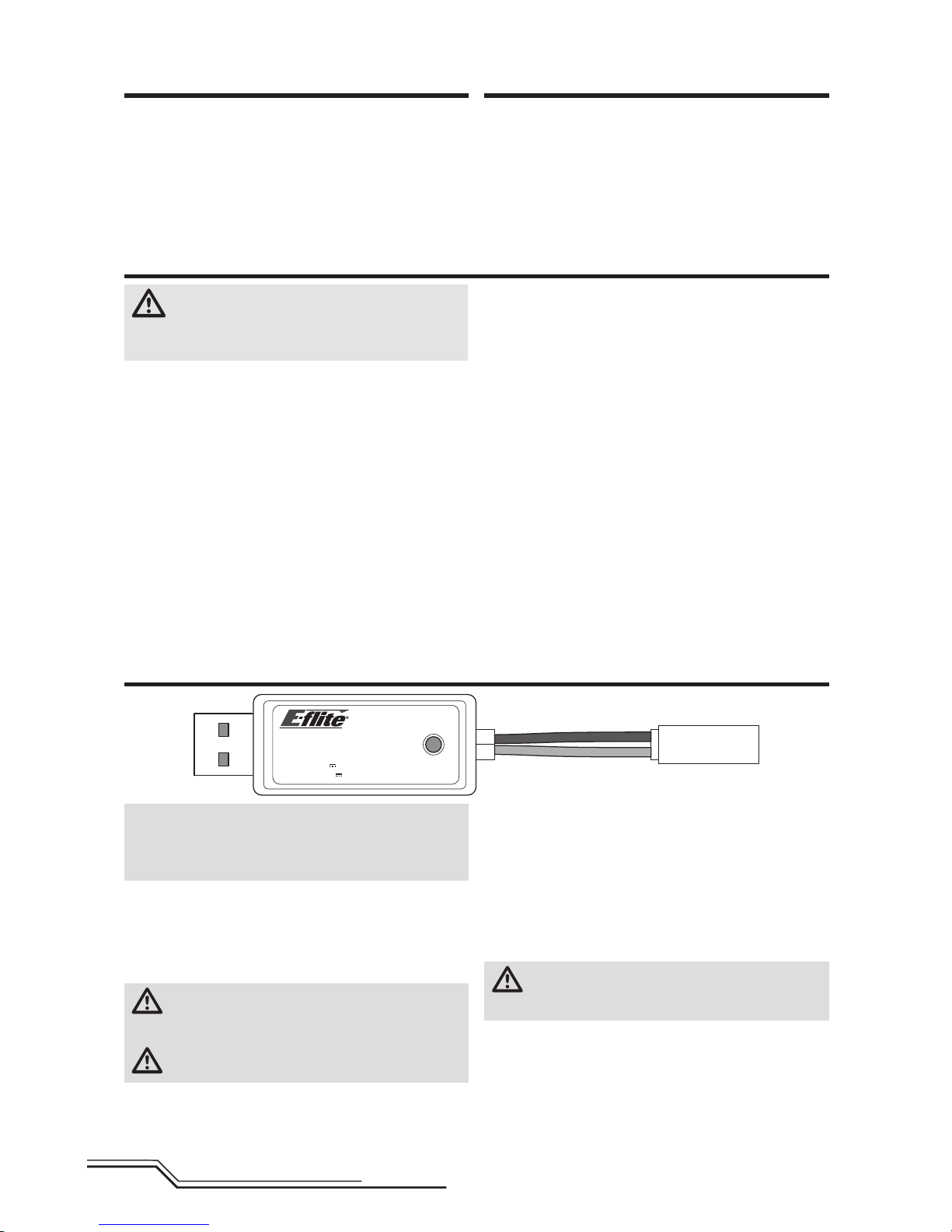
1. Insert the charger into a USB port.
2. Connect the battery to the charger lead, noting the
correct polarity.
3. Always disconnect the fl ight battery from the charger
immediately upon completion of charging.
CAUTION: Only use chargers specifi cally designed
to charge the included Li-Po battery. Failure to do so
could result in fi re, causing injury or property damage.
CAUTION: Never exceed the recommended
charge rate.
LED Indications
When you make the connection successfully, the LED on
the charger turns solid red, indicating charging has begun.
Charging a fully discharged (not over-discharged) 750mAh
battery takes approximately 60 minutes. The light goes off
when the charge is complete.
CHARGING (Solid Red)
MAX CHARGE (OFF)
CAUTION: Once charging is complete, immedi-
ately remove the battery. Never leave a battery
connected to the charger.
USB Li-Po
Charger
EFLC1014
SOLID RED LED
–Charging
DC Input:5.0V 750mA
DC Output:4.2V 700mA
LED OFF
–Charge
Complete
Page 5
5
EN
BNF Transmitter Setup
Program your transmitter before attempting to bind or fl y
the quadcopter. Transmitter programming values are shown
below for the Spektrum DX6i, DX7s, DX6, DX7, DX8, DX9
and DX18.
The fi les for models using Spektrum™ transmitters with
AirWare™ software are also available for download online
at www.spektrumrc.com.
Your quadcopter is also compatible with Spektrum DXe
radios with software version 1.3 or higher. Use the directions
below to reverse channel 6, or use the appropriate programming cable and the PC or mobile app to program the DXe.
We recommend downloading the Blade® Zeyrok™ DXe model
setup available at www.spektrumrc.com.
If you are programming your DXe using the PC or mobile
app, make sure the "Transmitter Channels" value is set to
the default of 7. If for any reason this value is changed
to 9, the Zeyrok will bind to the DXe, but will not respond to
control inputs.
If your DXe was included in another Blade Ready To Fly (RTF)
helicopter, the transmitter software will have to be updated
using the appropriate programming cable and either the
PC or mobile app available at www.spektrumrc.com.
Please note, the switch confi guration used for DXe transmitters included with the Blade 230 S RTF and Micro AH-64
Apache RTF varies from the standard DXe layout.
After reversing channel 6, bind the transmitter and
quadcopter normally.
Flight modes are controlled by the Flight Mode switch.
To use the DXe transmitter with the Zeyrok quadcopter, channel 6 must be reversed.
To reverse channel 6:
1. While powering on the DXe, hold the left and right sticks in the top-inside corners
as shown.
2. Re-center the sticks after the transmitter beeps. The LED will fl ash slowly.
3. To select a channel to reverse, move the right stick to the left or right and allow it
to re-center. Move the stick to the right to select the next channel. Move the stick
to the left to select the previous channel. The LED will fl ash rapidly corresponding
to the channel selected, as shown in the table. Select channel 6.
4. To reverse the selected channel, move the right stick up or down. The LED will
change color to indicate the new channel direction.
The LED will fl ash Orange to indicate the channel is normal.
The LED will fl ash Red to indicate the channel is reversed.
5. To store the changes, power off the DXe.
CAUTION: During the subsequent power up, always verify the throttle
direction is correct and keep clear of the motor and rotor blades. Failure to do
so may result in injury or damage to the product.
DXe
LED Flashes Channel
1 1-Throttle
2 2-Aileron
3 3-Elevator
4 4-Rudder
5 5-Flight Mode
6 6-Camera
7 7-Flaps
8 8-Aux Channel
Installing the Transmitter Batteries (RTF)
Replace the transmitter batteries when the
transmitter beeps rapidly.
Page 6
6
EN
Servo Setup
FUNCTION LISTSYSTEM SETUP
DX7s
D/R & Expo
Chan
Switch Pos (FLAP)
D/R
Expo*
AILE
0 100/100 0
1 100/100 0
2 75/75 0
ELEV
0 100/100 0
1 100/100 0
2 75/75 0
RUDD
0 100/100 0
1 100/100 0
2 75/75 0
Chan Travel Reverse
THR 100/100 Normal
AIL 100/100 Normal
ELE 100/100 Normal
RUD 100/100 Normal
Chan Travel Reverse
GER 100/100 Normal
AX1 100/100 Reverse
AX2 100/100 Normal
Model Type ACRO
SW Select
Trainer Aux 1
Flap Gear
All Others INH
* Use of "Expo" is not necessary for successful fl ight. The pilot may adjust this setting to tailor the sensitivity around
neutral if desired.
D/R & Expo
Chan Sw Pos D/R Expo*
AILE
0 100 INH
1 75 INH
ELEV
0 100 INH
1 75 INH
RUDD
0 100 INH
1 75 INH
Timer
Down Timer 5:00
Switch THR CUT
ADJUST LISTSETUP LIST
DX6i
TRAVEL ADJ
Channel Travel
THRO 100/100
AILE 100/100
ELEV 100/100
RUDD 100/100
GEAR 100/100
FLAP 100/100
REVERSE
Channel Direction
THRO N
AILE N
ELEV N
RUDD N
GEAR R
FLAP N
Modulation Type
AUTO DSMX-ENABLE
D/R COMBI
D/R SW AILE
Model Type Acro
Flight Mode Operation
Gear Sw: Pos 0, Elev D/R Sw: 0 or 1 = Stability Mode (internal quadcopter LED Green)
Gear Sw: Pos 1, Elev D/R Sw: 0 = Stagility Mode (internal quadcopter LED Yellow)
Gear Sw: Pos 1, Elev D/R Sw: 1 = Agility Mode (internal quadcopter LED Red)
Mixing
MIX 1 ACT
GEAR > GEAR ACT
RATE D 0% U –100%
SW
GEAR TRIM – INH
MIX 2
ACT
GEAR > GEAR
ACT
RATE
D 0% U +100%
SW
ELE D/R TRIM – INH
FLAPS
FLAP ELEV
NORM 100 0
LAND
100 0
Camera Control/
Continuous Flip**
Bind / I Button
Press twice rapidly (within 2 seconds) = still photo (rear LEDs blink once)
Press and hold 3 seconds = start/stop video (rear LEDs slowly fl ash while recording)
** If no camera is installed, pressing and holding the Bind button while in FM0 enables
the continuous fl ip feature (see the Flight Mode Selection section for details).
Camera Control/Continuous Flip**
Flap Switch
Set the switch position to 0 for normal. Set the switch to pos 1 until the rear LEDs slowly fl ash, then set it back to 0 to
start recording video. To stop recording, set the switch to pos 1 until the rear LEDs glow solid, then set it back to pos 0.
Quickly cycle the switch from pos 0 to pos 1 and back two times to take a photo.
Always return the fl ap switch to pos 0.
** If no camera is installed, switching the fl ap switch to pos 1 while in FM0 enables
the continuous fl ip feature (see the Flight Mode Selection section for details).
Flight Mode Operation
FLAP Sw: Pos 0 = Stability Mode
Pos 1 = Stagility Mode
Pos 2 = Agility Mode
Timer
Mode Count Down
Time 5:00 Tone
Start Throttle Out
Pos 25%
Page 7

7
EN
Servo Setup
FUNCTION LISTSYSTEM SETUP
DX8
SYSTEM SETUP
Model Type Airplane
F-Mode Setup
Switch 1 Switch B
Switch 2 Inhibit
Channel Assign
Channel Input
1 Throttle N/A
2 Aileron N/A
3 Elevator N/A
4 Rudder N/A
5 Gear B
6 AUX 1 I
Chan Travel Reverse
THR 100/100 Normal
AIL 100/100 Normal
ELE 100/100 Normal
RUD 100/100 Normal
GER 100/100 Normal
Chan Travel Reverse
AX1 100/100 Reverse
AX2 100/100 Normal
AX3 100/100 Normal
AX4 100/100 Normal
Servo Setup
FUNCTION LIST
DX6, DX7 (Gen 2), DX9, DX18
Timer
Mode Count Down
Time 5:00
Start Throttle Out
Over 25%
One Time Inhibit
D/R & Expo
Chan
Switch (F) Pos
D/R Expo*DX6
DX7, 9,
18
AILE
0 0 100/100 0
1 100/100 0
1 2 75/75 0
ELEV
0 0 100/100 0
1 100/100 0
1 2 75/75 0
RUDD
0 0 100/100 0
1 100/100 0
1 2 75/75 0
D/R & Expo
Chan
Switch Pos (AIL D/R)
D/R
Expo*
AILE
0 100/100 0
1 100/100 0
2 75/75 0
ELEV
0 100/100 0
1 100/100 0
2 75/75 0
D/R & Expo
Chan
Switch Pos (AIL D/R)
D/R
Expo*
RUDD
0 100/100 0
1 100/100 0
2 75/75 0
Chan Travel Reverse
THR 100/100 Normal
AIL 100/100 Normal
ELE 100/100 Normal
RUD 100/100 Normal
Chan Travel Reverse
GER 100/100 Normal
AX1 100/100 Reverse
AX2 100/100 Normal
Model Type ACRO
SW Select
Trainer Aux 1
F Mode Gear
All Others INH
Camera Control/
Continuous Flip**
Bind / I Button
Press twice rapidly (within 2 seconds) = still photo (rear LEDs blink once)
Press and hold 3 seconds = start/stop video (rear LEDs slowly fl ash while recording)
** If no camera is installed, pressing and holding the Bind button while in FM0 enables
the continuous fl ip feature (see the Flight Mode Selection section for details).
Camera Control/Continuous Flip**
Bind / I Button
Press twice rapidly (within 2 seconds) = still photo (rear LEDs blink once)
Press and hold 3 seconds = start/stop video (rear LEDs slowly fl ash while recording)
** If no camera is installed, pressing and holding the Bind button while in FM0 enables
the continuous fl ip feature (see the Flight Mode Selection section for details).
* Use of "Expo" is not necessary for successful fl ight. The pilot may adjust this setting to tailor the sensitivity around
neutral if desired.
Flight Mode Operation
Sw B: Pos 0 = Stability Mode
Pos 1 = Stagility Mode
Pos 2 = Agility Mode
Flight Mode Operation
FMODE Sw: Pos 0 = Stability Mode
Pos 1 = Stagility Mode
Pos 2 = Agility Mode
Timer
Mode Count Down
Time 5:00 Tone
Start Throttle Out
Pos 25%
Page 8

8
EN
Installing the Flight Battery
1. Lower the throttle stick to the lowest position
and center all trims.
2. Set the Flight Mode Switch to Stability Mode (FM0).
3. Power ON the transmitter.
4. Slide the battery into the back of the quadcopter, all
of the way forward through the battery loop as shown.
5. Connect the power lead to the battery, noting the correct
polarity.
CAUTION: Connecting the battery to the control
board with reversed polarity will cause damage
to the control board, the battery or both. Damage caused
by incorrectly connecting the battery is not covered
under warranty.
6. Place the quadcopter upright on a fl at surface and leave
it still until the LEDs glow solid white in the front and red
in the rear, indicating the quadcopter is ready for fl ight.
If the LEDs continuously pulse slowly, no valid transmitter signal has been acquired. Proceed to the Transmitter
and Receiver Binding section to bind the quadcopter and
transmitter.
If the LEDs alternately fl ash front and rear, the battery
is below 3.5V. The quadcopter will not allow takeoff.
Charge the battery and re-install.
If you experience issues during initialization, refer to the
Troubleshooting Guide at the back of the manual.
CAUTION: Always disconnect the Li-Po battery
from the aircraft when not fl ying to avoid overdischarging the battery. Batteries discharged to a voltage
lower than the lowest approved voltage may become
damaged, resulting in loss of performance and potential
fi re when batteries are charged.
To bind or re-bind your quadcopter to your chosen transmitter, please follow the directions below.
If you encounter problems, obey binding instructions and refer to the troubleshooting guide for other instructions.
If needed, contact the appropriate Horizon Product Support offi ce. For a list of compatible DSM
®
transmitters,
please visit www.bindnfl y.com.
Transmitter and Receiver Binding
General Binding Procedure (BNF)
1. Refer to the Transmitter Setup section to correctly setup your transmitter.
2. Lower the throttle stick to the lowest position and center all trims on your transmitter.
3. Power off the transmitter and move all switches to the 0 position.
4. Install the fl ight battery in the quadcopter. Hold the quadcopter inverted until the LEDs fl ash rapidly.
5. Set the quadcopter upright.
6. Put the transmitter into bind mode while powering on the transmitter.
7. The quadcopter is bound when the onboard LEDs stop fl ashing and then glow solid.
8. Disconnect the fl ight battery and power the transmitter off.
MLP6 Binding Procedure (RTF)
1. Disconnect the fl ight battery from the quadcopter.
2. Center all trims on your transmitter. The trims are centered when the transmitter emits a longer tone when pressing
the trim buttons.
3. Power off the transmitter and move the throttle stick to the down/off position.
4. Install the fl ight battery in the quadcopter. Hold the quadcopter inverted until the LEDs fl ash rapidly.
5. Set the quadcopter upright.
6. Push in and hold down the left stick (you will hear a ‘click’) while powering on the transmitter.
7. Release the left stick. The transmitter will beep and the power LED will blink.
8. The quadcopter is bound when the onboard LEDs stop fl ashing and then glow solid.
9. Disconnect the fl ight battery and power the transmitter off.
Your RTF transmitter comes prebound to the model. If you need to re-bind, follow the directions below.
Page 9

9
EN
RTF Transmitter Controls
D
E
C
B
Flight mode switch
Adjusting Flight Trims
The transmitter beeps each time the trim buttons are
pressed. The middle or neutral trim position is heard as a
longer tone. The end of the trim range is indicated by no
tone when the trim button is pushed.
Dual Rate Selection
The control sensitivity can be changed by pressing and
releasing the right control stick. The LED on the transmitter
will show solid for high sensitivity (default) and fl ashing for
low sensitivity.
Bind switch
Dual rate
switch
Camera Control/
Continuous Flip
ABCDE F
Mode 1
Aileron (Left/Right)
Throttle (Up/Down)
Throttle
Trim
Aileron
Trim
Rudder
Trim
Elevator
Trim
Rudder (Left/Right)
Elevator (Up/Down)
Mode 2
Aileron (Left/Right)
Elevator (Up/Down)
Elevator
Trim
Aileron
Trim
Rudder
Trim
Throttle
Trim
Rudder (Left/Right)
Throttle (Up/Down)
ON/OFF
Switch
Power LED/
Rate Indicator
A
F
Revolutionary SAFE
®
(Sensor Assisted Flight Envelope)
technology uses an innovative combination of multi-axis
sensors and software that allows model aircraft to know
its position relative to the horizon. This spatial awareness
is utilized to create a controlled fl ight envelope the aircraft
can use to maintain a safe region of bank and pitch angles
so you can fl y more safely. Far beyond stability, this level of
protection offers multiple modes so the pilot can choose to
develop his or her skills with a greater degree of security
and fl ight control that always feels crisp and responsive.
SAFE® technology delivers:
• Flight envelope protection you can enable at the fl ip of
a switch.
• Multiple modes let you adapt SAFE® technology to your
skill level instantly.
Best of all, sophisticated SAFE® technology doesn’t require
any work to enjoy. Every aircraft with SAFE® installed is
ready to use and optimized to offer the best possible fl ight
experience.
FlySAFERC.com
Technology
Page 10

10
EN
Elevator
Forward
Elevator down
Elevator up
Backward
Left Side View Left Side View
Rudder
Rudder left
Rudder right
Understanding the Primary Flight Controls
If you are not familiar with the controls of your quadcopter, take a few minutes to familiarize yourself with them before
attempting your fi rst fl ight.
Throttle
Throttle down
Throttle up
Left Side View Left Side View
Descend
Climb
Aileron
Aileron left
Left
Aileron right
Right
Rear ViewRear View
Nose Yaws Left Nose Yaws Right
Installing the Optional Camera (BNF)
1. Install the camera carrier halves around the camera. 2. Install the camera carrier to the landing gear using 2
screws. Ensure the ribbon cable does not get pinched by
the carrier clamp.
Page 11

11
EN
• In Stability Mode (FM0), the bank angle is limited. When the
sticks are released, the quadcopter will return to level fl ight.
If the camera is not installed on the quadcopter, the
continuous fl ip feature is available in Stability Mode.
To use the continuous fl ip feature, hold the continuous fl ip
button/switch and move the cyclic stick in any direction.
The quadcopter will begin fl ipping in the chosen direction when the cyclic stick is moved beyond 85% travel.
Release the fl ip button/switch to stop the rotation. Given
enough altitude, the quadcopter will self level and the
bank angle limits will be active.
If the cyclic stick is held after releasing the fl ip button, the
quadcopter will return to upright fl ight in the direction chosen.
NOTICE: When using the continuous fl ip feature, always
allow the quadcopter enough altitude to recover.
• In Stagility Mode (FM1), the bank angle is limited up
until 85% stick travel. Beyond 85% stick travel, the bank
angle is unlimited to allow for more advanced aerobatics.
If the sticks are released, the quadcopter will return to
level fl ight.
• In Agility Mode (FM2), the quadcopter has no bank angle
limits, and will not return to level fl ight if the sticks are
released. Use rates and expo to tune the performance
according to your fl ying style.
Refer to the Transmitter Setup Table for transmitter switch
selection and specifi c setup information.
Flight Mode Selection
Camera Controls
Consult your local laws and ordinances before choosing a
location to fl y your aircraft.
We recommend fl ying your aircraft outside in calm winds
or inside a large gymnasium. Always avoid fl ying near
houses, trees, wires and buildings. You should also be careful to avoid fl ying in areas where there are many people,
such as busy parks, schoolyards or soccer fi elds.
Takeo
Select Stability Mode (FM0). Slowly increase the throttle
until the motors start and the quadcopter begins to lift off.
Continue raising the throttle until the quadcopter is approximately 2 ft. (600mm) off the ground. Adjust the trims
so the model fl ies as desired. Once the trims are adjusted,
begin fl ying the model.
Flying the Zeyrok™ Quadcopter
Insert a micro SD card into the slot in the quadcopter until
it locks. Make sure the metal contact is facing up and the
notch in the card is facing forward as in the illustration.
Tweezers or small pliars may be necessary to install and
remove the micro SD card.
Power on the transmitter and quadcopter normally.
MLP6 RTF Transmitter users:
To take a still photo, quickly pull and release the camera
control switch twice. The rear LEDs on the quadcopter
will blink once as the camera takes the photo.
To start/stop recording video, pull and hold the camera
control switch for approximately 3 seconds. The rear
LEDs will begin fl ashing slowly, indicating the camera is
recording video. To stop the recording, pull and hold the
camera control switch for 3 seconds. The rear LEDs will
glow solid once again.
BNF Transmitter users:
Follow the instructions for your transmitter in the
Transmitter Setup section to control the camera.
To retrieve the video and photos from the camera:
Press the micro SD card in and release it to unlock. Pull
the card out from the quadcopter. Insert the card in the
micro to SD card adapter. The micro SD card can now be
read by any SD capable device.
3. Attach the camera control board to the landing gear
using 3 screws.
4. Connect the camera control cable to the quadcopter. The
black, negative terminal should go toward the rear of the
quadcopter. Attach the landing gear to the quadcopter
using 4 screws.
Page 12

12
EN
Post-Flight Inspection and Maintenance Checklist
LED Codes
√
Cleaning
Make sure the battery is not installed before cleaning. Remove dust and debris with a soft brush
or a dry, lint-free cloth.
Motors Replace the motor when the model will not fl y steady or veers off when doing a climb out.
Wiring Make sure the wiring does not block moving parts. Replace damaged wiring and loose connectors.
Fasteners
Make sure there are no loose screws, other fasteners or connectors. Do not over-tighten metal screws
in plastic parts. Tighten screws so the parts are mated together, then turn the screw only 1/8th of a turn
more. Do not use threadlock on or near plastic parts.
Propellers
Make sure there is no damage to the propellers or other parts that move at high speed. Damage to these
parts includes cracks, burrs, chips or scratches. Replace damaged parts before fl ying.
The quadcopter should not need large trim adjustments.
If excessive trim is required to sustain a reasonable hover,
perform the Drift Calibration.
Making small corrections on the transmitter, try to hold
the quadcopter in one spot. If fl ying in calm winds, the
model should require almost no corrective inputs. After
moving the cyclic stick and returning it to center, the
model should level itself. The quadcopter may continue to
move due to inertia. Move the cyclic stick in the opposite
direction to stop the movement.
Flying
With your quadcopter maintaining a stable low-level
hover, practice using the rudder, elevator and aileron controls to familiarize yourself with the machine’s responses
to control inputs. Remember to keep the control inputs as
minimal as possible.
When you are comfortable with basic fl ight, you may
explore the different fl ight modes and functions explained
in the Flight Mode Selection section of this manual. The
different fl ight modes are accessed using the Flight Mode
switch on the MLP6 or the controls programmed in the
BNF Transmitter Setup section.
Releasing the sticks in either of the Stability Modes will
allow the quadcopter to level itself. If you become disoriented, slowly lower the throttle stick to land softly.
Tip: If a greater bank angle is desired in Stability Mode,
refer to the Transmitter Setup section and increase
the “Travel” values of the rudder, aileron and elevator channels in your transmitter to over 100%.
If for any reason the quadcopter loses the transmitter
signal, the quadcopter will enter a “panic” state. The quadcopter will self-level while throttling down for 5 seconds.
After 5 seconds, the quadcopter will disarm and power to
the motors will be removed.
Typical fl ight time for the included battery is approximately
10 minutes.
Low Voltage Cuto (LVC)
LVC decreases the power to the motors when the battery
voltage gets low. The LEDs on the quadcopter will alternately fl ash, front and rear, indicating low battery voltage.
Full throttle control is maintained for approximately 5
seconds, after which motor speed is ramped down for the
next 5 seconds. When the LEDs indicate low voltage, land
immediately.
NOTICE: Crash damage is not covered under warranty.
NOTICE: Repeated fl ying to LVC will damage the battery.
LVC does not prevent the battery from over-discharge
during storage.
Landing
To land, slowly decrease the throttle while in a low-level
hover. After landing, lower the throttle completely to stop
the motors. Disconnect and remove the battery from the
quadcopter to prevent over discharge. During storage,
make sure the battery charge does not fall below 3V per
cell.
External Quadcopter LEDs
Single rapid fl ash = Power on
Rapid fl ash, front and rear = Bind mode
Slow fl ashing, front and rear = Looking for signal/Loss
of signal
Solid, front and rear = Ready for fl ight
Alternating front and rear fl ashing = Battery below 3.5V
(LVC). Will not allow takeoff. If it occurs during fl ight,
power is limited to allow landing.
Solid front, slow fl ashing rear = Video recording
Solid front, rear single fl ash off = Photo capture
RTF Transmitter
Solid = High rate selected (default)
Flashing = Low rate selected
Page 13

13
EN
Dri Calibration
The quadcopter has been calibrated at the factory before shipment, but it is possible that a crash will cause
mechanical distortion of the frame, resulting in a slight drift in Stability and Stagility modes. In this situation,
please follow the calibration procedure below.
Before beginning the calibration procedure, fully charge the fl ight battery and ensure the quadcopter and transmitter
are bound properly, per the binding instructions.
To Calibrate the Zeyrok quadcopter:
1. Power on the transmitter and quadcopter normally.
2. Set the transmitter to fl ight mode 1.
3. Refer to the
illustrations at
right. Depending
on which control
layout mode your
transmitter uses,
move the control
sticks to the
positions shown
and press the
camera button
until the LEDs on
the quadcopter
go off.
(approximately
5 seconds).
4. Release the sticks and camera button.
5. Do not move the quadcopter.
6. The rear LEDs will glow solid red when the calibration is
complete and successful.
If the rear LEDs fl ash continuously, the calibration was
not successful. Power off the quadcopter and attempt the
calibration procedure again.
7. Restart the quadcopter normally.
Mode 2
Mode 1
Replacing the Propellers
Follow the steps below to replace any damaged propellers:
1. Remove the screw at the base of the propeller and pull
the propeller straight up.
2. Note the propellers and the quadcopter are marked
“A” or “B” to show the proper location for each
propeller, as shown in the illustration. Replace the
propeller making sure to line up the screw holes in the
propeller with the hole in the prop shaft.
3. Replace the screw at the base of the propeller.
Do not use thread lock on the screws.
Do not overtighten the screws.
Page 14

14
EN
Troubleshooting Guide
Problem Possible Cause Solution
Quadcopter does not function
and smells burnt after connecting the flight battery
Flight battery connected with the
wrong polarity
Replace the 3-in-1 board. Connect the fl ight
battery noting proper polarity
Quadcopter will not respond to
throttle
Throttle too high and/or throttle trim
is too high
Reset controls with the throttle stick
and throttle trim at the lowest setting
Aileron, elevator or rudder trims are
not centered
Center all trims
Quadcopter has reduced fl ight
time or is underpowered
Flight battery charge is low Completely recharge the fl ight battery
Inadequate power to fl ight battery
charger
Use a different power source for the charger
Flight battery is damaged
Replace the fl ight battery and follow the fl ight
battery instructions
Flight conditions too cold
Make sure the battery is warm
(room temperature) before use
Diffi culty binding
Transmitter too near aircraft during
binding process
Power off the transmitter. Move the transmitter
a larger distance from the aircraft. Disconnect
and reconnect the fl ight battery to the
Quadcopter. Follow the binding instructions
Bind switch or button was not held
while transmitter was powered on
Power off transmitter and repeat bind process
Quadcopter or transmitter is too close
to large metal object, wireless source
or another transmitter
Move quadcopter and transmitter to another
location and attempt binding again
Diffi culty connecting
(after binding)
Less than a 5-second wait between
fi rst powering on the transmitter and
powering on the quadcopter
Leave the transmitter powered on. Power off
the quadcopter and power it back on
The quadcopter is bound to a
different model memory
(ModelMatch™ transmitters only)
Select the correct model memory on the
transmitter. Disconnect and reconnect the
fl ight battery to the quadcopter
Flight battery or transmitter battery
charge is too low
Replace or recharge batteries
Quadcopter or transmitter is too close
to large metal object, wireless source
or another transmitter
Move quadcopter and transmitter to another
location and attempt connecting again
Crashes immediately upon
lift-off
Propellers in wrong locations or
incorrect fl ight mode selected
Ensure propeller direction and motor direction
are correct
Aileron, elevator or rudder are
reversed in the transmitter
Ensure aileron, elevator or rudder are not
reversed
Quadcopter does not complete
initialization
Quadcopter moved during initialization
Allow the quadcopter to sit still until it
initializes completely
Propeller will not spin
or spins roughly
Stripped drive gear Replace affected drive gear
Pinion gear out of adjustment Adjust the pinion gear mesh
Page 15

15
EN
1
1
2*
8
8
4
5
5
11
11
11
4
8
6
6
8
10
7
9*
3
Exploded View
Parts Listings
Part # Description
BLH7302 Landing Gear
BLH7309 Camera w/landing gear
DXe DSMX Transmitter Only
DX6 DSMX 6-Channel Transmitter Only
DX6i DSMX 6-Channel Transmitter Only
Part # Description
DX7 DSMX 7-Channel Transmitter Only
DX8 DSMX 8-Channel Transmitter Only
DX9 DSMX 9-Channel Transmitter Only
DX18 DSMX 18-Channel Transmitter Only
Optional Parts
Part # Description
1 BLH7301 Main Frame
2 BLH7302 Landing Gear (included with BLH7360)
3 BLH7303 Prop Set, Yel, Grn, Blk (6)
4 BLH7304 Prop Shaft Set (4)
5 BLH7305 Drive Gear Set (4)
6 BLH7306 LED Set
7 BLH7307 3-in-1 Control Unit
Part # Description
8 BLH7308 Motors (2)
9 BLH7309
Camera w/landing gear
(included with BLH7360)
10
EFLB7501S25
750mAh 1S 3.7V 25C LiPo Battery
11 BLH1115 Bearings
BLH7310 Decal Sheet
EFLC1014 1S USB Li-Po Charger, 700mA, JST
* Included with BLH7360 only.
Optional parts for BLH7300 and BLH7380.
Page 16

16
EN
Limited Warranty
What this Warranty Covers
Horizon Hobby, LLC, (Horizon) warrants to the original purchaser that the product purchased (the “Product”) will be free from
defects in materials and workmanship at the date of purchase.
What is Not Covered
This warranty is not transferable and does not cover (i) cosmetic damage, (ii) damage due to acts of God, accident, misuse,
abuse, negligence, commercial use, or due to improper use,
installation, operation or maintenance, (iii) modification of or to
any part of the Product, (iv) attempted service by anyone other
than a Horizon Hobby authorized service center, (v) Product not
purchased from an authorized Horizon dealer, (vi) Product not
compliant with applicable technical regulations, or (vii) use that
violates any applicable laws, rules, or regulations.
OTHER THAN THE EXPRESS WARRANTY ABOVE, HORIZON
MAKES NO OTHER WARRANTY OR REPRESENTATION, AND
HEREBY DISCLAIMS ANY AND ALL IMPLIED WARRANTIES,
INCLUDING, WITHOUT LIMITATION, THE IMPLIED WARRANTIES
OF NON-INFRINGEMENT, MERCHANTABILITY AND
FITNESS FOR A PARTICULAR PURPOSE. THE PURCHASER
ACKNOWLEDGES THAT THEY ALONE HAVE DETERMINED THAT
THE PRODUCT WILL SUITABLY MEET THE REQUIREMENTS OF
THE PURCHASER’S INTENDED USE.
Purchaser’s Remedy
Horizon’s sole obligation and purchaser’s sole and exclusive
remedy shall be that Horizon will, at its option, either (i) service,
or (ii) replace, any Product determined by Horizon to be defective. Horizon reserves the right to inspect any and all Product(s)
involved in a warranty claim. Service or replacement decisions
are at the sole discretion of Horizon. Proof of purchase is
required for all warranty claims. SERVICE OR REPLACEMENT
AS PROVIDED UNDER THIS WARRANTY IS THE PURCHASER’S
SOLE AND EXCLUSIVE REMEDY.
Limitation of Liability
HORIZON SHALL NOT BE LIABLE FOR SPECIAL, INDIRECT,
INCIDENTAL OR CONSEQUENTIAL DAMAGES, LOSS OF
PROFITS OR PRODUCTION OR COMMERCIAL LOSS IN ANY
WAY, REGARDLESS OF WHETHER SUCH CLAIM IS BASED IN
CONTRACT, WARRANTY, TORT, NEGLIGENCE, STRICT LIABILITY
OR ANY OTHER THEORY OF LIABILITY, EVEN IF HORIZON HAS
BEEN ADVISED OF THE POSSIBILITY OF SUCH DAMAGES.
Further, in no event shall the liability of Horizon exceed the
individual price of the Product on which liability is asserted. As
Horizon has no control over use, setup, final assembly, modification or misuse, no liability shall be assumed nor accepted
for any resulting damage or injury. By the act of use, setup
or assembly, the user accepts all resulting liability. If you as
the purchaser or user are not prepared to accept the liability
associated with the use of the Product, purchaser is advised to
return the Product immediately in new and unused condition to
the place of purchase.
Law
These terms are governed by Illinois law (without regard to
conflict of law principals). This warranty gives you specific
legal rights, and you may also have other rights which vary
from state to state. Horizon reserves the right to change or
modify this warranty at any time without notice.
WARRANTY SERVICES
Questions, Assistance, and Services
Your local hobby store and/or place of purchase cannot provide
warranty support or service. Once assembly, setup or use of
the Product has been started, you must contact your local
distributor or Horizon directly. This will enable Horizon to better
answer your questions and service you in the event that you
may need any assistance. For questions or assistance, please
visit our website at www.horizonhobby.com, submit a Product
Support Inquiry, or call the toll free telephone number referenced in the Warranty and Service Contact Information section
to speak with a Product Support representative.
Inspection or Services
If this Product needs to be inspected or serviced and is compliant in the country you live and use the Product in, please use
the Horizon Online Service Request submission process found
on our website or call Horizon to obtain a Return Merchandise
Authorization (RMA) number. Pack the Product securely
using a shipping carton. Please note that original boxes may
be included, but are not designed to withstand the rigors of
shipping without additional protection. Ship via a carrier that
provides tracking and insurance for lost or damaged parcels,
as Horizon is not responsible for merchandise until it arrives
and is accepted at our facility. An Online Service Request is
available at http://www.horizonhobby.com/content/_servicecenter_render-service-center. If you do not have internet
access, please contact Horizon Product Support to obtain
a RMA number along with instructions for submitting your
product for service. When calling Horizon, you will be asked
to provide your complete name, street address, email address
and phone number where you can be reached during business
hours. When sending product into Horizon, please include your
RMA number, a list of the included items, and a brief summary
of the problem. A copy of your original sales receipt must
be included for warranty consideration. Be sure your name,
address, and RMA number are clearly written on the outside of
the shipping carton.
NOTICE: Do not ship Li-Po batteries to Horizon. If you have
any issue with a Li-Po battery, please contact the appropriate
Horizon Product Support office.
Warranty Requirements
For Warranty consideration, you must include your orig-
inal sales receipt verifying the proof-of-purchase date.
Provided warranty conditions have been met, your Product will
be serviced or replaced free of charge. Service or replacement
decisions are at the sole discretion of Horizon.
Non-Warranty Service
Should your service not be covered by warranty, ser-
vice will be completed and payment will be required
without notification or estimate of the expense unless
the expense exceeds 50% of the retail purchase cost.
By submitting the item for service you are agreeing to payment of the service without notification. Service estimates are
available upon request. You must include this request with your
item submitted for service. Non-warranty service estimates
will be billed a minimum of ½ hour of labor. In addition you
will be billed for return freight. Horizon accepts money orders
and cashier’s checks, as well as Visa, MasterCard, American
Express, and Discover cards. By submitting any item to Horizon
for service, you are agreeing to Horizon’s Terms and Conditions
found on our website http://www.horizonhobby.com/content/_
service-center_render-service-center.
ATTENTION: Horizon service is limited to Product compliant in the country of use and ownership. If received,
a non-compliant Product will not be serviced. Further,
the sender will be responsible for arranging return
shipment of the un-serviced Product, through a carrier
of the sender’s choice and at the sender’s expense.
Horizon will hold non-compliant Product for a period
of 60 days from notification, after which it will be discarded.
10/15
Page 17

17
EN
Warranty and Service Contact Information
Country of Purchase Horizon Hobby Contact Information Address
United States of
America
Horizon Service Center
(Repairs and Repair Requests)
servicecenter.horizonhobby.com/
RequestForm/
4105 Fieldstone Rd
Champaign, Illinois, 61822 USA
Horizon Product Support
(Product Technical Assistance)
productsupport@horizonhobby.com
877-504-0233
Sales
websales@horizonhobby.com
800-338-4639
United Kingdom
Service/Parts/Sales:
Horizon Hobby Limited
sales@horizonhobby.co.uk
Units 1–4 , Ployters Rd, Staple Tye
Harlow, Essex, CM18 7NS, United
Kingdom
+44 (0) 1279 641 097
Germany
Horizon Technischer Service service@horizonhobby.de
Christian-Junge-Straße 1
25337 Elmshorn, Germany
Sales: Horizon Hobby GmbH +49 (0) 4121 2655 100
France
Service/Parts/Sales:
Horizon Hobby SAS
infofrance@horizonhobby.com
11 Rue Georges Charpak
77127 Lieusaint, France
+33 (0) 1 60 18 34 90
EU Compliance Statement:
Horizon Hobby, LLC hereby declares that this
product is in compliance with the essential requirements
and other relevant provisions of the R&TTE, EMC, and LVD
Directives.
A copy of the EU Declaration of Conformity is available
online at:
http://www.horizonhobby.com/content/support-rendercompliance.
Compliance Information for the European Union
Instructions for disposal of WEEE by users in the European Union
This product must not be disposed of with
other waste. Instead, it is the user’s responsibility to dispose of their waste equipment
by handing it over to a designated collections
point for the recycling of waste electrical and
electronic equipment. The separate collection
and recycling of your waste equipment at the
time of disposal will help to conserve natural resources and
make sure that it is recycled in a manner that protects human
health and the environment. For more information about where
you can drop off your waste equipment for recycling, please
contact your local city offi ce, your household waste disposal
service or where you purchased the product.
FCC Statement
This equipment has been tested and found to comply with
the limits for Part 15 of the FCC rules. These limits are
designed to provide reasonable protection against harmful
interference in a residential installation. This equipment
generates uses and can radiate radio frequency energy and,
if not installed and used in accordance with the instructions,
may cause harmful interference to radio communications.
However, there is no guarantee that interference will not
occur in a particular installation. If this equipment does
cause harmful interference to radio or television reception,
which can be determined by turning the equipment off and
on, the user is encouraged to try to correct the interference
by one or more of the following measures:
• Reorient or relocate the receiving antenna.
• Increase the separation between the equipment and
receiver.
• Connect the equipment to an outlet on a circuit different
from that to which the receiver is connected.
This device complies with part 15 of the FCC rules. Operation
is subject to the following two conditions: (1) This device
may not cause harmful interference, and (2) this device must
accept any interference received, including interference that
may cause undesired operation.
NOTICE: Modifi cations to this product will void the user’s
authority to operate this equipment.
IC Information
Under Industry Canada regulations, this radio transmitter
may only operate using an antenna of a type and maximum
(or lesser) gain approved for the transmitter by Industry
Canada. To reduce potential radio interference to other users,
the antenna type and its gain should be so chosen that the
equivalent isotropically radiated power (e.i.r.p.) is not more
than that necessary for successful communication.
This device complies with Industry Canada licence-exempt
RSS standard(s). Operation is subject to the following two
conditions: (1) this device may not cause interference, and
(2) this device must accept any interference, including
interference that may cause undesired operation of the
device.”
Page 18

68
IT
©2016 Horizon Hobby, LLC.
Blade, E-fl ite, Zeyrok, SAFE, the SAFE logo, DSM, DSM2, DSMX, the BNF logo, AirWare, ModelMatch and the Horizon Hobby logo
are trademarks or registered trademarks of Horizon Hobby, LLC. The Spektrum trademark is used with permission of
Bachmann Industries, Inc. All other trademarks, service marks or logos are property of their respective owners. Patents pending.
Created 2/16 48024 BLH7300, BLH7360, BLH7380
 Loading...