

Page 1

Instruction Manual
Bedienungsanleitung
Manuel d’utilisation
Manuale di Istruzioni
®
Page 2

2
EN
• Always keep a safe distance in all directions around your model to avoid
collisions or injury. This model is controlled by a radio signal subject to
interference from many sources outside your control. Interference can
cause momentary loss of control.
• Always operate your model in open spaces away from full-size vehicles,
traffi c and people.
• Always carefully follow the directions and warnings for this and any optional
support equipment (chargers, rechargeable battery packs, etc.).
• Always keep all chemicals, small parts and anything electrical out of the
reach of children.
• Always avoid water exposure to all equipment not specifi cally designed and
protected for this purpose. Moisture causes damage to electronics.
• Never place any portion of the model in your mouth as it could cause serious
injury or even death.
• Never operate your model with low transmitter batteries.
• Always keep aircraft in sight and under control.
• Always move the throttle fully down at rotor strike.
• Always use fully charged batteries.
• Always keep transmitter powered on while aircraft is powered.
• Always remove batteries before disassembly.
• Always keep moving parts clean.
• Always keep parts dry.
• Always let parts cool after use before touching.
• Always remove batteries after use.
• Never operate aircraft with damaged wiring.
• Never touch moving parts.
Age Recommendation: Not for children under 14 years. This is not a toy.
WARNING AGAINST COUNTERFEIT PRODUCTS: If you ever need to replace a Spektrum component found in a Horizon Hobby product, always purchase from
Horizon Hobby, LLC or a Horizon Hobby authorized dealer to ensure authentic high-quality Spektrum product. Horizon Hobby, LLC disclaims all support and
warranty with regards, but not limited to, compatibility and performance of counterfeit products or products claiming compatibility with DSM or Spektrum.
WARNING: Read the ENTIRE instruction manual to become familiar with the features of the product before operating. Failure to operate the product correctly
can result in damage to the product, personal property and cause serious injury.
This is a sophisticated hobby product. It must be operated with caution and common sense and requires some basic mechanical ability. Failure to operate this Product
in a safe and responsible manner could result in injury or damage to the product or other property. This product is not intended for use by children without direct
adult supervision. Do not use with incompatible components or alter this product in any way outside of the instructions provided by Horizon Hobby, LLC. This manual
contains instructions for safety, operation and maintenance. It is essential to read and follow all the instructions and warnings in the manual, prior to assembly, setup or
use, in order to operate correctly and avoid damage or serious injury.
The following terms are used throughout the product literature to indicate various levels of potential harm when operating this product:
NOTICE: Procedures, which if not properly followed, create a possibility of physical property damage AND a little or no possibility of injury.
CAUTION: Procedures, which if not properly followed, create the probability of physical property damage AND a possibility of serious injury.
WARNING: Procedures, which if not properly followed, create the probability of property damage, collateral damage, and serious injury OR create a high probability of
superfi cial injury.
NOTICE
All instructions, warranties and other collateral documents are subject to change at the sole discretion of Horizon Hobby, LLC. For up-to-date product literature, visit
horizonhobby.com and click on the support tab for this product.
Meaning of Special Language
Safety Precautions and Warnings
Page 3

3
EN
Table of Contents
Safety Precautions and Warnings ........................................................................ 2
Table of Contents ................................................................................................. 3
First Flight Preparation ......................................................................................... 4
Flying Checklist ................................................................................................... 4
Low Voltage Cutoff (LVC) ...................................................................................... 4
Transmitter Setup ................................................................................................ 4
Installing the Flight Battery .................................................................................. 5
Transmitter and Receiver Binding ......................................................................... 5
Throttle Hold ........................................................................................................ 5
Control Tests ........................................................................................................ 6
Flying the Blade Trio 360 CFX .............................................................................. 7
Gyro Gain Adjustment ..........................................................................................8
Blade Helicopter Belt Tension .............................................................................. 8
Post-Flight Inspections and Maintenance ............................................................. 8
Troubleshooting Guide ......................................................................................... 8
Limited Warranty ................................................................................................. 9
Warranty and Service Contact Information ......................................................... 10
FCC Information ................................................................................................. 10
IC Information .................................................................................................... 10
Compliance Information for the European Union ................................................. 10
Exploded View / Explosionszeichnung / Vue Éclatée / Vista Esplosa .................... 40
Parts List / Ersatzteile / Pièces de Rechange / Pezzi di Ricambio ........................ 42
Optional Parts / Optionale Bauteile / Pièces optionnelles / Pezzi opzionali ........... 43
Box Contents:
• Blade Trio 360 CFX
®
Length
26.4 in (670mm)
Height
8.5 in (215mm)
Main Rotor Diameter
31.1 in (790mm)
Tail Rotor Diameter
6.9 in (175mm)
Flying Weight
30 oz (850 g)
Specifi cations
To receive product updates, special offers and more, register your product at www.bladehelis.com.
Page 4
4
EN
Low Voltage Cuto (LVC)
The ESC will continuously lower power to the motor until complete shutdown
when the battery reaches 18V under load. This helps prevent over-discharge of the
Li-Po battery. Land immediately when the ESC activates LVC. Continuing to fl y after
LVC can damage the battery, cause a crash or both. Crash damage and batteries
damaged due to over-discharge are not covered under warranty.
Repeatedly fl ying the helicopter until LVC activates will damage the helicopter
battery.
Disconnect and remove the Li-Po battery from the aircraft after use to prevent
trickle discharge. During storage, make sure battery charge does not fall below
3V per cell.
First Flight Preparation
• Remove and inspect contents
• Begin charging the fl ight battery
• Program your computer transmitter
• Install the fl ight battery in the helicopter (once it has been fully charged)
• Bind your transmitter
• Familiarize yourself with the controls
• Find a suitable area for fl ying
Flying Checklist
❏ Always turn the transmitter on fi rst
❏ Plug the fl ight battery into the lead from the ESC
❏ Allow the ESC to initialize and arm properly
❏ Fly the model
❏ Land the model
❏ Unplug the fl ight battery from the ESC
❏ Always turn the transmitter off last
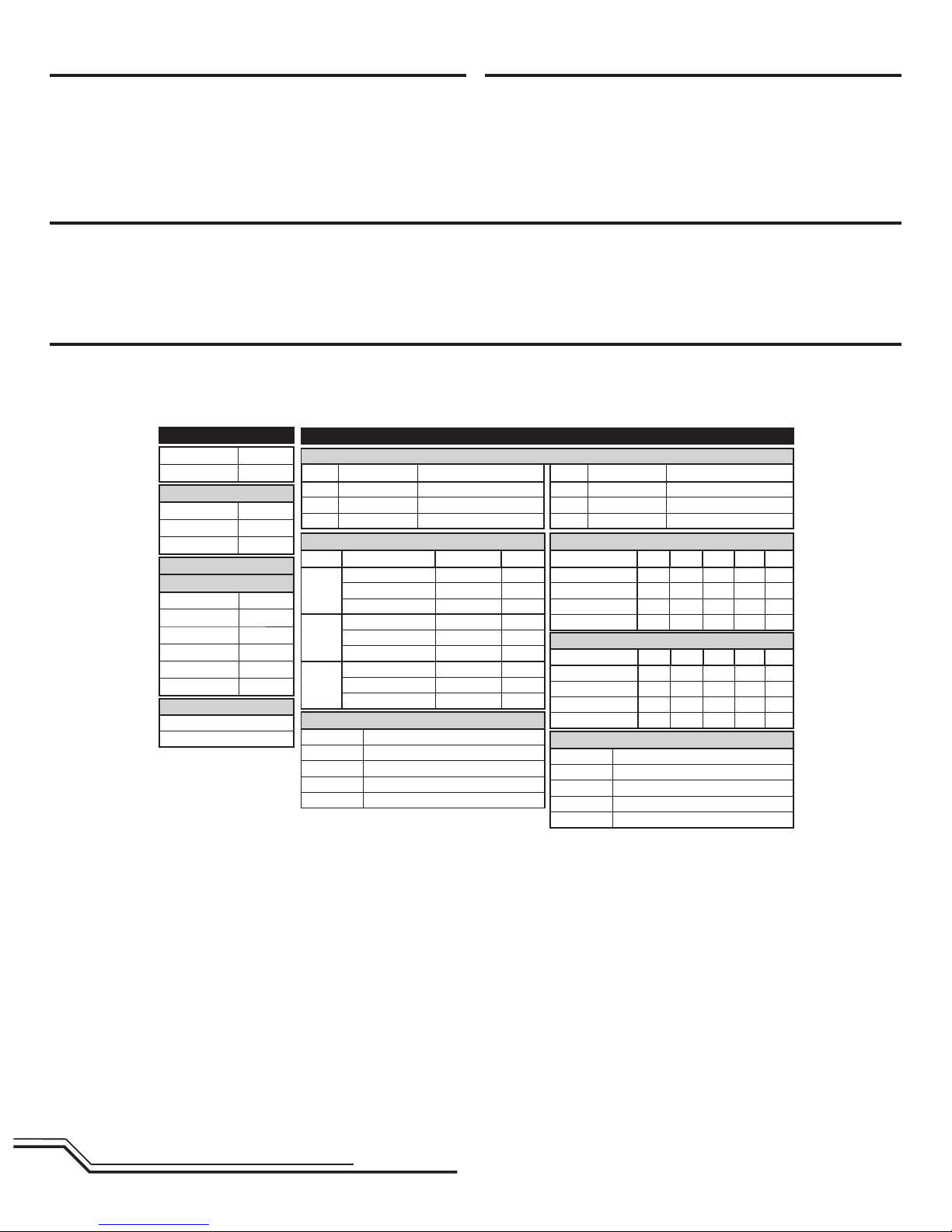
Transmitter Setup
Program your transmitter before attempting to bind or fl y the helicopter.
Transmitter programming values are shown below for the Spektrum DX6,
DX7 (Gen 2), DX8 (Gen 2), DX9, DX18 and DX20.
The fi les for models using Spektrum™ transmitters with AirWare™ software are
also available for download online at www.spektrumrc.com.
Timer
Mode Count Down
Time 3:00
Start Throttle Out
Over 25%
One Time Inhibit
Gyro
Pos 0 58%
Pos 1 48%
Pos 2 40%
Channel Gear
SW B
Chan Travel Reverse
THR 130/110 Normal
AIL 100/100 Reverse
ELE 100/100 Reverse
Chan Travel Reverse
RUD 100/100 Reverse
GER 100/100 Normal
PIT 100/100 Reverse
Servo Setup
FUNCTION LIST
DX6, DX7 (Gen 2), DX8 (Gen 2), DX9, DX18, DX20
D/R & Expo
Chan Switch (F) Pos D/R Expo
AILE
0 100/100 0
1 85/85 0
2 85/85 0
ELEV
0 100/100 0
1 85/85 0
2 85/85 0
RUDD
0 100/100 0
1 85/85 0
2 85/85 0
SETUP LIST
Throttle Curve
Switch (B) Pos Pt 1 Pt 2 Pt 3 Pt 4 Pt 5
N 0 30 30 30 30
17575757575
2 100 100 100 100 100
HOLD 0 0 0 0 0
Model Type HELI
Swash Type Normal
Pitch Curve
Switch (B) Pos Pt 1 Pt 2 Pt 3 Pt 4 Pt 5
N 30 40 50 75 100
1 0 25 50 75 100
2 0 25 50 75 100
HOLD 0 25 50 75 100
F-Mode Setup
Switch 1 Switch B
Switch 2 Inhibit
Hold Switch Switch H
Channel Assign
Channel Input Confi g
1 Throttle
2 Aileron
3 Elevator
4 Rudder
5 Flight Mode Switch B
6 Collective
Frame Rate
22ms
DSMX
Page 5
5
EN
WARNING: You must move the throttle to the LOW/OFF position during
binding. Failure to do so may cause the rotor blades to spin and the
helicopter to lift during the AR7210BX initialization, which could result in
damage to property and injury.
NOTICE: Remove the bind plug to prevent the system from entering bind mode
the next time the power is turned on.
If you encounter problems, obey binding instructions and refer to transmitter
troubleshooting guide for other instructions. If needed, contact the appropriate
Horizon Product Support offi ce.
Transmitter and Receiver Binding
Throttle Hold
Throttle hold only turns off the motor on an electric helicopter. You maintain pitch
and direction control.
The blades will spin if throttle hold is OFF. For safety, turn throttle hold ON any time
you need to touch the helicopter or check the direction controls.
Throttle hold is also used to turn off the motor if the helicopter is out of control, in
danger of crashing, or both.
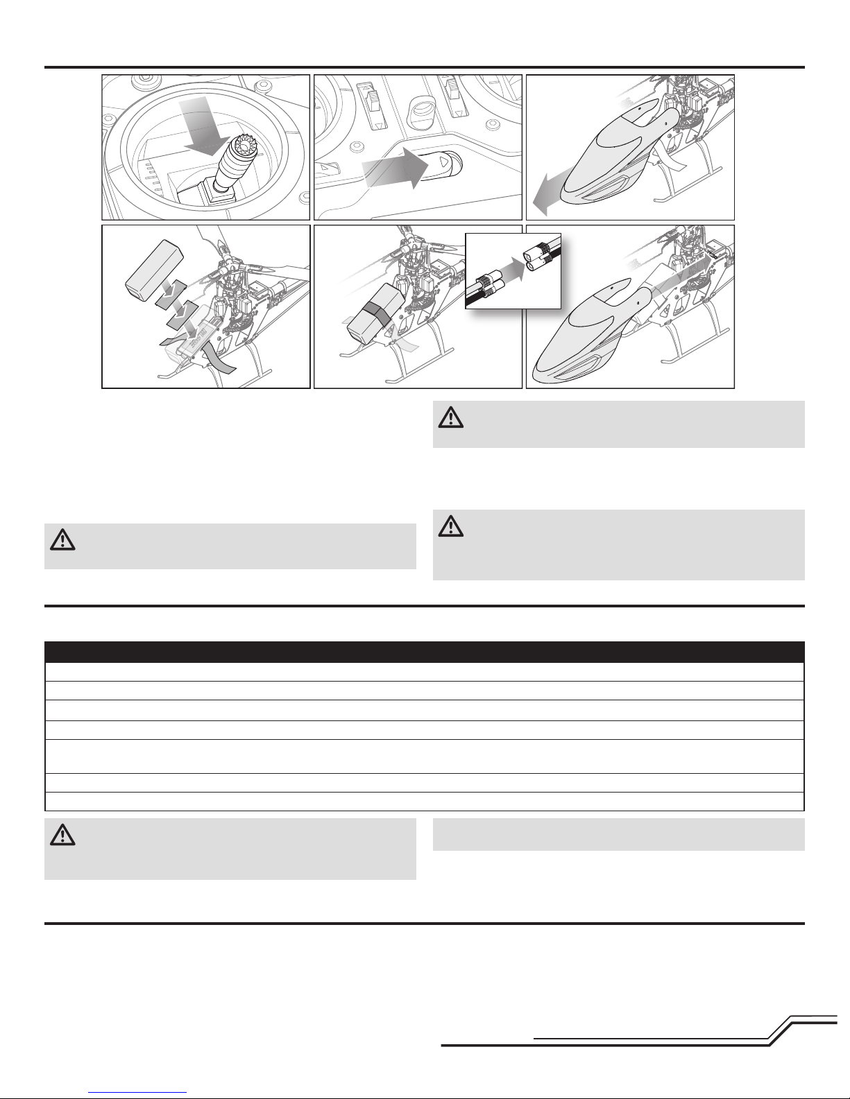
Installing the Flight Battery
1. Lower the throttle.
2. Power on the transmitter.
3. Center the throttle trim.
4. To allow the ESC to arm and to keep rotors from initiating at startup, turn on
throttle hold and normal fl ight mode before connecting the fl ight battery.
5. Attach hook material to the helicopter frame and loop material to the battery.
6. Install the fl ight battery on the helicopter frame. Secure the fl ight battery with a
hook and loop strap. Connect the battery cable to the ESC.
CAUTION: Always keep the power lead positioned AWAY from the
elevator servo. Failure to do so could cause the lead to get caught,
resulting in a crash causing property damage and injury.
CAUTION: Make sure the fl ight battery does not come in contact with the
motor. Failure to do so will cause the motor, ESC and battery to overheat,
resulting in a crash causing property damage and injury.
7. Do not move the helicopter until the AR7210BX initializes. The swashplate will
move up and down, indicating that the unit is ready. The AR7210BX will also
emit a solid BLUE Status LED when it is ready.
8. The helicopter motor will emit 2 tones, incdicating the ESC is armed.
CAUTION: Always disconnect the Li-Po battery from the aircraft
receiver when not fl ying to avoid over-discharging the battery. Batteries
discharged to a voltage lower than the lowest approved voltage may become
damaged, resulting in loss of performance and potential fi re when batteries are
charged.
Binding Procedure
1. Program your transmitter using the Transmitter Setup found in this manual.
2. Insert the bind plug in the BND/DAT port on the receiver.
3. Connect the fl ight battery to the ESC. The H menu LED should be fl ashing, indicating the AR7210BX is in bind mode.
4. Move the throttle stick to the desired failsafe position (low throttle position in normal mode).
5. Follow the procedures of your specifi c transmitter to enter Bind Mode. The system will connect within a few seconds. Once connected, the H LED will turn off and
the AR7210BX will start the initialization process.
6. When the initialization process is complete, the Status LED light will come ON solid BLUE.
7. Disconnect the fl ight battery and remove the bind plug from the AR7210BX. Store the bind plug in a convenient place.
Binding is the process of programming the receiver to recognize the GUID (Globally
Unique Identifi er) code of a single specifi c transmitter. You need to ‘bind’ your
chosen Spektrum™ DSM2/DSMX technology equipped aircraft transmitter to the
receiver for proper operation.
Page 6

6
EN
Cyclic and Collective Control Test
Elevator
Aileron
Rear ViewRear View
Collective Pitch
Rudder
1. Power on the transmitter.
2. Turn TH HOLD ON and put transmitter in normal mode.
3. Connect the helicopter battery to the ESC.
NOTICE: Do not allow the helicopter to move until the Status LED is solid blue
and all menu LEDs are OFF. The gyro will not operate correctly if the helicopter
moves before the Status LED is solid blue.
4. Move the rudder stick to the right. The
tail rotor blades move as shown. If they
do not move as shown, reverse the rudder
channel in the transmitter (refer to your
transmitter manual for instructions).
5. Release the rudder control. Manually turn
the helicopter nose to the left. The tail rotor blades automatically move as shown.
If they do not move as shown, refer to the
AR7210BX manual for information on reversing the tail sensor direction
(Setup menu point F).
Cyclic
When using a fl ybarless rotor head, you are controlling rotational rates while the
AR7210BX controls the servos. You are not directly controlling the servos with the
transmitter.
It is normal for the swashplate to slowly move back to its original position
after a stick input and for the servos to not move at the same speed as your
control sticks.
1. Tilt the helicopter forward. The swashplate should tilt backward.
2. Tilt the helicopter backward. The swashplate should tilt forward.
3. Roll the helicopter left. The swashplate should roll right.
4. Roll the helicopter right. The swashplate should roll left.
5. If the swashplate does not move in the correct direction, you will need to
reverse the cyclic sensor direction. Refer to the AR7210BX manual for more
information (Setup menu point M).
Control Tests
CAUTION: You must complete the Rudder and Cyclic tests prior to fl ight. Failure to complete the tests ensuring the sensor directions are not reversed can cause
the helicopter to crash, resulting in property damage and injury.
WARNING: To prevent accidental motor startup and possible damage to property or personal injury, always disconnect the motor wires from the ESC prior to
performing the cyclic and collective control tests.
Left Side View
Left Side View Left Side View
Left Side View
Page 7

7
EN
Consult local laws and ordinances before choosing a location to fl y your aircraft.
• Always keep aircraft in sight and under control
• Always turn on throttle hold at loss of control or rotor strike
• Always use fullly charged batteries
• Always keep transmitter powered on while aircraft is powered
• Always remove batteries before disassembly
• Always keep moving parts clean
• Always keep parts dry
• Always let parts cool after use before touching
• Always remove batteries after use
• Always keep people and pets at least 30 feet away when
the fl ight battery is connected
• Never operate aircraft with damaged wiring
Never touch moving parts Select a large, open area away from people and objects. Your fi rst fl ights should be outdoors in low-wind conditions. Always stay at
least 30 feet (10 meters) away from the helicopter when it is fl ying.
The Blade Trio 360 CFX is intended to be fl own outdoors.
CAUTION: This helicopter is intended for pilots with experience
fl ying aerobatic, collective pitch helicopters. The helicopter is more
responsive than other Blade helicopters. If you are not an experienced 3D or
collective pitch helicopter pilot, do not attempt to fl y this product.
Takeoff
Deliberately increase throttle and establish a hover at least 24” (0.6 meter) high,
outside of ground effect.
CAUTION: Do not give any aileron, elevator or rudder commands before
takeoff or the helicopter may crash during takeoff.
Flying
The helicopter lifts off the ground when the rotor head reaches a suitable speed.
Establish a low-level hover to verify proper operation of your helicopter. Do not set
any trim; the fl ybarless design of the Blade 360 CFX renders trim unnecessary.
Setting trim or sub-trim can cause an unwanted drift or rotation of the helicopter.
First fl ights should be performed in normal mode and low cyclic and rudder dual
rates until you are familiar with the fl ying manner. Discover the rates that fi t your
fl ying style.
CAUTION: Always fl y the helicopter with your back to the sun and the
wind to prevent loss of fl ight control.
Landing
Establish a low level hover. Deliberately lower the throttle until the helicopter
lands. Do not give any aileron, elevator or rudder commands when the helicopter
is landing.
When the helicopter is in stunt mode:
• The Castle Creations Talon 35 ESC comes pre-programmed in Governor mode.
To alter the settings, use the Castle Creations “Castle Link”. Do not adjust the
throttle curve in the transmitter.
• The rotor head speed is constant.
• The main rotor will increase negative pitch as the throttle/collective stick is
moved from the middle stick position to the low stick position. Negative pitch
allows the helicopter to fl y upside down and perform aerobatics.
Change between stunt and idle up modes in a hover with the throttle near the
hovering stick position.
WARNING: Do not use wooden main blades with this helicopter or injury
and/or property damage could occur. Only use Blade approved carbon fi ber
main blades.
Motor
Re-connect the motor wires to the ESC prior to attempting the motor test. Place
the helicopter outdoors on a clean, fl at and level surface (concrete or asphalt) free
of obstructions. Always stay clear of moving rotor blades.
1. The motor beeps twice when the helicopter’s ESC arms properly. Before you
continue, confi rm that TH HOLD is ON.
WARNING: The motor will spin when throttle is increased while TH HOLD
is OFF.
2. Check the swashplate directions to ensure they are moving in the correct
direction. Please refer to the diagrams for reference.
WARNING: Stay at least 30 feet (10 meters) away from the helicopter
when the motor is running. Do not attempt to fl y the helicopter at this
time.
3. Ensure the throttle is lowered completely. Confi rm the transmitter is still set
to normal fl ight mode. Turn throttle hold off at this time. Slowly increase the
throttle until the blades begin to spin. The main blades spin clockwise when
viewing the helicopter from the top. The tail rotor blades spin counterclockwise
when viewing the helicopter from the right-hand side.
Flying the Blade Trio 360 CFX
❏ Check all screws and ensure that they are tight
❏ Check belt tension and ensure that it is not too tight or too loose
❏ Check main and tail blades to ensure they are not damaged
❏ Check all links and make sure they move freely but do not pop off easily
❏ Check that fl ight battery and transmitter battery are fully charged
❏ Check all wires to ensure that they are not cut, pinched, or chaffed
and are properly secured
❏ Check all wire connections
❏ Check gears and make sure no teeth are missing
❏ Do a complete control test
❏ Check that servos are functioning properly
❏ Check to make sure fl ight battery is properly secured
❏ Check to make sure AR7210BX is properly secured
Pre-Flight Checklist
Page 8

8
EN
Troubleshooting Guide
Problem Possible Cause Solution
Helicopter will not bind
to the transmitter
(during binding)
Low fl ight battery or transmitter battery voltage Fully charge or replace the fl ight battery and/or transmitter batteries
AR7210BX is not in bind mode Make sure the bind plug is connected to the AR7210BX BND/DAT port
Transmitter is not in bind mode
Power on the transmitter while holding the Trainer/Bind switch. Hold the Trainer/Bind switch
until binding is complete
Transmitter too close to the helicopter during binding
process
Power off the transmitter. Move the transmitter to a larger distance from the helicopter.
Disconnect and reconnect the fl ight battery to the helicopter and follow binding instructions
Helicopter will not link
to the transmitter
(after binding)
Helicopter is bound to a different model memory
(ModelMatch radios only)
Disconnect the fl ight battery. Select the correct model memory on the transmitter
Reconnect the fl ight battery
Flight battery/Transmitter battery charge is too low Replace or recharge batteries
AR7210BX will not
initialize
The helicopter was moved during initialization Lay the helicopter on its side during initialization if windy
The transmitter is powered off Power on the transmitter
Controls are not centered Center elevator, aileron and rudder controls. Make sure the throttle is at idle
Helicopter will not
respond to the throttle but
responds to other controls
Throttle not at idle and/or throttle trim is too high Lower the throttle stick and lower the throttle trim
The transmitter is not in normal mode or throttle
hold is on
Make sure the transmitter is in normal mode and throttle hold is off
The motor is not connected to the ESC or the motor
wires are damaged
Connect the motor wires to the ESC and check motor wires for damage
Flight battery charge is too low Replace or recharge fl ight battery
Throttle channel is reversed Reverse the throttle channel on the transmitter
Gyro Gain Adjustment
• If the tail wags or oscillates, lower the gain on the gyro.
On your transmitter’s gyro menu, decrease the gyro gain values a small amount
at a time until the helicopter is stable within a particular fl ight mode.
• If the tail is drifting while hovering, increase the gain on the gyro.
On your transmitter, increase the gyro gain values a small amount at a time until
the tail starts to wag/oscillate. Afterwards, reduce the gain until the tail stops
wagging/oscillating within a particular fl ight mode.
Post-Flight Inspections and Maintenance
Ball Links
Make sure the plastic ball link holds the control ball, but is not tight (binding) on the ball. When a link is too loose on the ball, it can separate from the ball
during fl ight and cause a crash. Replace worn ball links before they fail.
Cleaning Make sure the battery is not connected before cleaning. Remove dust and debris with a soft brush or a dry lint free cloth.
Bearings Replace bearings when they become notchy (sticky in places when turning) or draggy.
Wiring Make sure wiring does not block moving parts. Replace damaged wiring and loose connectors.
Fasteners
Make sure there are no loose screws, other fasteners or connectors. Do not over tighten metal screws in plastic parts. Tighten screw so parts are mated
together, then turn screw only 1/8th of a turn more.
Rotors
Make sure there is no damage to rotor blades and other parts which move at high speed. Damage to these parts includes cracks, burrs, chips or scratches.
Replace damaged parts before fl ying.
Gyro
Make sure the AR7210BX is securely attached to the frame. Replace the double-sided tape when necessary. The helicopter will crash if the AR7210BX
separates from the helicopter frame.
Blade Helicopter Belt Tension
Belt tension that is too tight results in loss of power and causes the belt to wear more quickly. Tension that is too loose can cause belt damage and loss of tail rotor
control in fl ight.
To check for proper belt tension:
1. View the tail rotor drive belt through the opening at the back of the main
frame.
2. Use a hex wrench or standard screwdriver to compress the belt through the
opening.
3. Apply light pressure on the belt, compressing the belt toward the left side of
the tail boom.
4. The belt tension is correct if the compressed side of the belt reaches approximately halfway to the opposite side of the belt.
a. If the compressed side of the belt reaches farther than halfway to the
other side of the belt, the tension is too loose.
b. If the compressed side of the belt does not reach halfway to the other
side of the belt, the tension is too tight.
To adjust belt tension:
1. Loosen the two horizontal stabilizer screws.
2. Loosen the 2 screws at the
back of the main frame.
3. Slide the boom forward
or aft to adjust the belt
tension.
4. When the belt tension is
properly adjusted, tighten
the 2 screws at the back
of the frame.
5. Tighten the horizontal
stabilizer screws.
Page 9

9
EN
Problem Possible Cause Solution
Helicopter power
is lacking
Flight battery has low voltage Fully charge the fl ight battery
Flight battery is old or damaged Replace the fl ight battery
Flight battery cells are unbalanced Fully charge the fl ight battery, allowing the charger time to balance the cells
Excessive current is being drawn through the BEC Check all servos and the helicopter motor for damage
Tail drive belt tension is not correct See "Checking Tail Drive Belt Tension" in this manual
Helicopter will not lift off
Main rotor head is not spinning in the correct
direction
Make sure the main rotor head is spinning clockwise. Refer to the motor control test
Transmitter settings are not correct Check throttle and pitch curve settings and pitch control direction
Flight battery has low voltage Fully charge the fl ight battery
Main rotor blades are installed backwards Install the main rotor blades with the thicker side as the leading edge
The helicopter tail spins
out of control
Rudder control and/or sensor direction reversed Make sure the rudder control and the rudder sensor are operating in the correct direction
Tail servo is damaged Check the rudder servo for damage and replace if necessary
Inadequate control arm throw Check the rudder control arm for adequate travel and adjust if necessary
Tail belt is too loose Make sure the tail drive belt tension is adjusted correctly
The helicopter wobbles
in fl ight
Cyclic gain is too high Decrease Dial 1 on the AR7210BX
Headspeed is too low
Increase the helicopter's head speed via your transmitter settings and/or using a freshly
charged fl ight pack
Dampers are worn Replace the main rotor head dampers
Limited Warranty
What this Warranty Covers
Horizon Hobby, LLC, (Horizon) warrants to the original purchaser that the product
purchased (the “Product”) will be free from defects in materials and workmanship at
the date of purchase.
What is Not Covered
This warranty is not transferable and does not cover (i) cosmetic damage, (ii) damage
due to acts of God, accident, misuse, abuse, negligence, commercial use, or due to
improper use, installation, operation or maintenance, (iii) modifi cation of or to any part
of the Product, (iv) attempted service by anyone other than a Horizon Hobby authorized
service center, (v) Product not purchased from an authorized Horizon dealer, (vi)
Product not compliant with applicable technical regulations, or (vii) use that violates
any applicable laws, rules, or regulations.
OTHER THAN THE EXPRESS WARRANTY ABOVE, HORIZON MAKES NO OTHER
WARRANTY OR REPRESENTATION, AND HEREBY DISCLAIMS ANY AND ALL IMPLIED
WARRANTIES, INCLUDING, WITHOUT LIMITATION, THE IMPLIED WARRANTIES OF
NON-INFRINGEMENT, MERCHANTABILITY AND FITNESS FOR A PARTICULAR PURPOSE.
THE PURCHASER ACKNOWLEDGES THAT THEY ALONE HAVE DETERMINED THAT
THE PRODUCT WILL SUITABLY MEET THE REQUIREMENTS OF THE PURCHASER’S
INTENDED USE.
Purchaser’s Remedy
Horizon’s sole obligation and purchaser’s sole and exclusive remedy shall be that
Horizon will, at its option, either (i) service, or (ii) replace, any Product determined by
Horizon to be defective. Horizon reserves the right to inspect any and all Product(s)
involved in a warranty claim. Service or replacement decisions are at the sole
discretion of Horizon. Proof of purchase is required for all warranty claims. SERVICE
OR REPLACEMENT AS PROVIDED UNDER THIS WARRANTY IS THE PURCHASER’S
SOLE AND EXCLUSIVE REMEDY.
Limitation of Liability
HORIZON SHALL NOT BE LIABLE FOR SPECIAL, INDIRECT, INCIDENTAL OR
CONSEQUENTIAL DAMAGES, LOSS OF PROFITS OR PRODUCTION OR COMMERCIAL
LOSS IN ANY WAY, REGARDLESS OF WHETHER SUCH CLAIM IS BASED IN CONTRACT,
WARRANTY, TORT, NEGLIGENCE, STRICT LIABILITY OR ANY OTHER THEORY OF
LIABILITY, EVEN IF HORIZON HAS BEEN ADVISED OF THE POSSIBILITY OF SUCH
DAMAGES. Further, in no event shall the liability of Horizon exceed the individual price
of the Product on which liability is asserted. As Horizon has no control over use, setup,
fi nal assembly, modifi cation or misuse, no liability shall be assumed nor accepted for
any resulting damage or injury. By the act of use, setup or assembly, the user accepts
all resulting liability. If you as the purchaser or user are not prepared to accept the
liability associated with the use of the Product, purchaser is advised to return the
Product immediately in new and unused condition to the place of purchase.
Law
These terms are governed by Illinois law (without regard to confl ict of law principals).
This warranty gives you specifi c legal rights, and you may also have other rights which
vary from state to state. Horizon reserves the right to change or modify this warranty
at any time without notice.
WARRANTY SERVICES
Questions, Assistance, and Services
Your local hobby store and/or place of purchase cannot provide warranty support
or service. Once assembly, setup or use of the Product has been started, you must
contact your local distributor or Horizon directly. This will enable Horizon to better
answer your questions and service you in the event that you may need any assistance.
For questions or assistance, please visit our website at www.horizonhobby.com,
submit a Product Support Inquiry, or call the toll free telephone number referenced in
the Warranty and Service Contact Information section to speak with a Product Support
representative.
Inspection or Services
If this Product needs to be inspected or serviced and is compliant in the country you
live and use the Product in, please use the Horizon Online Service Request submission
process found on our website or call Horizon to obtain a Return Merchandise
Authorization (RMA) number. Pack the Product securely using a shipping carton.
Please note that original boxes may be included, but are not designed to withstand
the rigors of shipping without additional protection. Ship via a carrier that provides
tracking and insurance for lost or damaged parcels, as Horizon is not responsible for
merchandise until it arrives and is accepted at our facility. An Online Service Request
is available at http://www.horizonhobby.com/content/_service-center_render-servicecenter. If you do not have internet access, please contact Horizon Product Support to
obtain a RMA number along with instructions for submitting your product for service.
When calling Horizon, you will be asked to provide your complete name, street
address, email address and phone number where you can be reached during business
hours. When sending product into Horizon, please include your RMA number, a list of
the included items, and a brief summary of the problem. A copy of your original sales
receipt must be included for warranty consideration. Be sure your name, address, and
RMA number are clearly written on the outside of the shipping carton.
NOTICE: Do not ship Li-Po batteries to Horizon. If you have any issue with a Li-Po
battery, please contact the appropriate Horizon Product Support offi ce.
Page 10

10
EN
Compliance Information for the European Union
Warranty and Service Contact Information
Warranty Requirements
For Warranty consideration, you must include your original sales receipt
verifying the proof-of-purchase date. Provided warranty conditions have been
met, your Product will be serviced or replaced free of charge. Service or replacement
decisions are at the sole discretion of Horizon.
Non-Warranty Service
Should your service not be covered by warranty, service will be completed
and payment will be required without notifi cation or estimate of the expense
unless the expense exceeds 50% of the retail purchase cost. By submitting
the item for service you are agreeing to payment of the service without notifi cation.
Service estimates are available upon request. You must include this request with your
item submitted for service. Non-warranty service estimates will be billed a minimum
of ½ hour of labor. In addition you will be billed for return freight. Horizon accepts
money orders and cashier’s checks, as well as Visa, MasterCard, American Express,
and Discover cards. By submitting any item to Horizon for service, you are agreeing to
Horizon’s Terms and Conditions found on our website http://www.horizonhobby.com/
content/_service-center_render-service-center.
ATTENTION: Horizon service is limited to Product compliant in the country of
use and ownership. If received, a non-compliant Product will not be serviced.
Further, the sender will be responsible for arranging return shipment of the
un-serviced Product, through a carrier of the sender’s choice and at the
sender’s expense. Horizon will hold non-compliant Product for a period of 60
days from notifi cation, after which it will be discarded. 10/15
This equipment has been tested and found to comply with the limits for Part 15 of
the FCC rules. These limits are designed to provide reasonable protection against
harmful interference in a residential installation. This equipment generates uses and
can radiate radio frequency energy and, if not installed and used in accordance with
the instructions, may cause harmful interference to radio communications.
However, there is no guarantee that interference will not occur in a particular
installation. If this equipment does cause harmful interference to radio or television
reception, which can be determined by turning the equipment off and on, the user
is encouraged to try to correct the interference by one or more of the following
measures:
• Reorient or relocate the receiving antenna.
• Increase the separation between the equipment and receiver.
• Connect the equipment to an outlet on a circuit different from that to which the
receiver is connected.
This device complies with part 15 of the FCC rules. Operation is subject to the
following two conditions: (1) This device may not cause harmful interference, and
(2) this device must accept any interference received, including interference that
may cause undesired operation.
NOTICE: Modifi cations to this product will void the user’s authority to operate
this equipment.
FCC Information
IC Information
This device complies with Industry Canada licence-exempt RSS standard(s).
Operation is subject to the following two conditions: (1) this device may not
cause interference, and (2) this device must accept any interference, including
interference that may cause undesired operation of the device.”
Country of Purchase Horizon Hobby Contact Information Address
United States of America
Horizon Service Center
(Repairs and Repair Requests)
servicecenter.horizonhobby.com/RequestForm/
4105 Fieldstone Rd
Champaign, Illinois, 61822 USA
Horizon Product Support
(Product Technical Assistance)
productsupport@horizonhobby.com
877-504-0233
Sales
websales@horizonhobby.com
800-338-4639
United Kingdom
Service/Parts/Sales:
Horizon Hobby Limited
sales@horizonhobby.co.uk
Units 1–4 , Ployters Rd, Staple Tye
Harlow, Essex, CM18 7NS, United Kingdom
+44 (0) 1279 641 097
Germany
Horizon Technischer Service service@horizonhobby.de
Christian-Junge-Straße 1
25337 Elmshorn, Germany
Sales: Horizon Hobby GmbH +49 (0) 4121 2655 100
France
Service/Parts/Sales:
Horizon Hobby SAS
infofrance@horizonhobby.com
11 Rue Georges Charpak
77127 Lieusaint, France
+33 (0) 1 60 18 34 90
EU Compliance Statement:
Horizon Hobby, LLC hereby declares that this product is in compliance
with the essential requirements and other relevant provisions of the
R&TTE and EMC Directives.
A copy of the EU Declaration of Conformity is available online at:
http://www.horizonhobby.com/content/support-render-compliance.
Instructions for disposal of WEEE by users in the European Union
This product must not be disposed of with other waste. Instead, it is the user’s responsibility to dispose of their waste equipment by handing it over to a
designated collections point for the recycling of waste electrical and electronic equipment. The separate collection and recycling of your waste equipment at
the time of disposal will help to conserve natural resources and make sure that it is recycled in a manner that protects human health and the environment.
For more information about where you can drop off your waste equipment for recycling, please contact your local city offi ce, your household waste disposal
service or where you purchased the product.
Page 11

40
Exploded View / Explosionszeichnung / Vue Éclatée / Vista Esplosa
25
46
47
47
47
47
47
21
23
24
15
22
13
20
19
19
19
17
18
16
16
16
Page 12

41
27
31
14
44
2
32
32
32
35
49
49
38
36
49
34
30
37
29
28
51
Page 13

42
Parts List / Ersatzteile / Pièces de Rechange / Pezzi di Ricambio
46
6
43
12
12
1119
12
12
43
41
40
42
4
3
50
39
5
11
10
12
12
12
9
9
9
11
12
7
7
7
8
7
7
5
# Part # English Deutsch Français Italiano
1 BLH1636
Control/Linkage Ball, Short (10):
360 CFX
Blade Kugelköpfe kurz (10): 360 CFX
Tringleries courtes/rotules (10) : 360
CFX
Sfere per i rinvii, corte (10): 360 CFX
2 BLH1645 Landing Gear Set: 360 CFX Blade Landegestell: 360CFX Train d’atterrissage: 360 CFX Set carrello di atterraggio: 360 CFX
3 BLH1657
Tail Servo Boom Mount (2):
360 CFX
Blade Heckrohr (2): 360CFX Support de servo d’anticouple: 360 CFX
Supporto servo per tubo coda (2):
360 CFX
4 BLH1660
Tail Pushrod Support/Guide Set:
360 CFX
Blade Halter Heckrotoranlenkstange:
360CFX
Guide de tringlerie d’anticouple: 360
CFX
Set supporto/guida per comando coda:
360 CFX
5 BLH1662A
Aluminum Horizontal Stab Fin
Mount: 360 CFX
Blade Aluminium Leitwerksbefestigung/ Heckfi nne: 360 CFX
Support de stabilisateur en aluminium:
360 CFX
Supporto in alluminio per piano di coda
orizzontale: 360 CFX
6 BLH1672C
Stab/Fin Set, Carbon Fiber:
360 CFX
Carbon Leitwerk / Heckfi nne :
360 CFX
Dérive et stabilisateur en carbone:
360 CFX
Set piani di coda, fi bra di carbonio:
360 CFX
7 BLH1663 Tail Case Set: 360 CFX Blade Heckrotor Gehäuse: 360 CFX Boîtier d’anticouple: 360 CFX Set scatola coda: 360 CFX
8 BLH1665
Tail Rotor Shaft and Drive Pulley
(2): 360 CFX
Blade Heckrotorschaft (2): 360 CFX Axe d’anticouple: 360 CFX
Albero rotore di coda con puleggia (2):
360 CFX
9 BLH1667
Tail Rotor Pitch Lever Set:
360 CFX
Blade Heckrotor Anlenkungset: 360
CFX
Levier d’anticouple: 360 CFX
Set leva passo per rotore di coda:
360 CFX
10 BLH1668
Tail Rotor Pitch Control Slider
Set: 360 CFX
Heckrotorschiebehülse Set : 360 CFX Coulisseau d’anticouple: 360 CFX
Set cursore controllo passo rotore di
coda: 360 CFX
11 BLH1669 Tail Rotor Hub Set: 360 CFX Heckrotor Zentralstück Set : 360 CFX Moyeu d’anticouple: 360 CFX Set mozzo rotore di coda: 360 CFX
12 BLH1670
Tail Rotor Blade Grip/Holder Set:
360 CFX
Blatthalter Heckrotor: 360 CFX Pieds de pales d’anticouple: 360 CFX Set portapala rotore di coda: 360 CFX
13 BLH1901 Helical Main Gear: 360 CFX Hauptzahnrad schrägverz.: 360 CFX Couronne principale hélicoïdale: 360 CFX Ingranaggio principale elicoidale: 360 CFX
14 BLH1904 Helical Pinion, 12T: 360 CFX Ritzel 12 Z schrägverz.: 360 CFX Pignon 12T hélicoïdal: 360 CFX Pignone elicoidale, 12T: 360 CFX
15 BLH4304 Main Blade Shims (4): 360 CFX
Unterlegscheiben Rotorblatthalter (4):
360 CFX
Rondelles de pales principales (4): 360
CFX
Spessori per pala principale (4): 360 CFX
16 BLH4701 Fbl Main Rotor Grip Set: 360 CFX Rotorblatthalterset: 360 CFX Pieds de pales principales FBL: 360 CFX
Set portapala Fbl rotore principale: 360
CFX
17 BLH4702 Fbl Main Grip Arms: 360 CFX Rotorblatthalter: 360 CFX
Leviers de pieds de pales principales:
360 CFX
Bracci portapala principale Fbl: 360 CFX
18 BLH4703 Fbl Linkage Set: 360 CFX Flybarlessanlenkungen: 360 CFX Tringleries Fbl: 360 CFX Set rinvii Fbl: 360 CFX
19 BLH4706 Dampers (4): 360 CFX Dämpfer (4): 360 CFX Amortisseurs (4): 360 CFX Smorzatori (4): 360 CFX
Page 14

43
Optional Parts / Optionale Bauteile / Pièces optionnelles / Pezzi opzionali
Part # English Deutsch Français Italiano
EFLB13006S30 1300 mAh 6S 22.2V 30C LiPo 1300 mAh 6S 22,2 V 30 C LiPo Li-Po 6S 22,2V 1300mA 30C 1300 mAh 6S 22.2 V 30C LiPo
# Part # English Deutsch Français Italiano
20 BLH4707 Fbl Follower Arms: 360 CFX
Taumelscheibenmitnehmer: 360
CFX
Bras FBL: 360 CFX Fbl Squadretta rinvio: 360 CFX
21 BLH4708 Main Shaft (2): 360 CFX Hauptrotorwelle (2): 360 CFX Axe principal: 360 CFX Albero principale (2): 360 CFX
22 BLH4709 Aluminum Swashplate: 360 CFX Taumelscheibe Aluminum: 360 CFX Plateau cyclique en aluminium: 360 CFX Piatto oscillante in alluminio: 360 CFX
23 BLH4710 Belt Drive Pulley: 360 CFX Zahnriemenspannrad : 360 CFX
Poulie de transmission d’anticouple:
360 CFX
Puleggia per cinghia: 360 CFX
24 BLH4711
One-Way Bearing Hub w/One
way bearing: 360 CFX
Freilauf: 360 CFX Roue libre avec moyeu: 360 CFX
Mozzo con cuscinetto a ruota libera:
360 CFX
25 BLH4712 Stock FG Canopy: 360 CFX Kabinenhaube: 360 CFX Bulle d’origine en fi bre: 360 CFX Capottina FG di serie: 360 CFX
26 BLH4713 Optional FG Canopy: 360 CFX optionale Haube: 360 CFX Bulle optionnelle en fi bre: 360 CFX Capottina FG opzionale: 360 CFX
27 BLH4714 CF Main Frame Set: 360 CFX Hauptrahmen: 360 CFX Flancs de châssis en carbone: 360 CFX Set telaio principale CF: 360 CFX
28 BLH4715 Battery Tray: 360 CFX Akkuhalter: 360 CFX Support de batterie: 360 CFX Supporto batteria: 360 CFX
29 BLH4716 Servo Mounting Blocks: 360 CFX Servohalter: 360 CFX Paliers de fi xation de servos: 360 CFX Blocchi supporto servi: 360 CFX
30 BLH4717 Lower Bearing Block: 360 CFX Lagerblock unten: 360 CFX Palier inférieur: 360 CFX Blocco cuscinetto inferiore: 360 CFX
31 BLH4718 Bottom Plate: 360 CFX Bodenplatte: 360 CFX Platine inférieure: 360 CFX Piastra inferiore: 360 CFX
32 BLH4719 Landing Gear Mounts: 360 CFX Halter Kufengestell: 360 CFX Supports de train d’atterrissage: 360 CFX Supporti carrello: 360 CFX
33 BLH4720 Linkage Set: 360 CFX Anlenkungsset: 360 CFX Tringleries: 360 CFX Set rinvii di collegamento: 360 CFX
34 BLH4721 Anti-Rotation Bracket: 360 CFX Taumelscheibenführung: 360 CFX Guide de plateau cyclique: 360 CFX Staffa antirotazione: 360 CFX
35 BLH4722 Motor Mount: 360 CFX Motorhalter: 360 CFX Support moteur: 360 CFX Supporto motore: 360 CFX
36 BLH4723 Tail Boom Clamp: 360 CFX Heckauslegerklampe: 360 CFX Fixation de poutre de queue: 360 CFX Supporto tubo coda: 360 CFX
37 BLH4724 Belt Tensioner: 360 CFX Riemenspanner: 360 CFX Tendeur de courroie: 360 CFX Tenditore cinghia: 360 CFX
38 BLH4725 Canopy Posts: 360 CFX Blade 360 CFX: Kabinenhaubenhalter Supports de bulle: 360 CFX Appoggi capottina: 360 CFX
39 BLH4726 Boom Support Set: 360 CFX
Blade 360 CFX: Heckauslegerhalter
Set
Renforts de poutre: 360 CFX Set supporto tubo: 360 CFX
40 BLH4727 Boom (2): 360 CFX Heckrohr: 360 CFX Poutre (2): 360 CFX Tubo coda (2): 360 CFX
41 BLH4728 Tail Drive Belt: 360 CFX Heckrotorriemen: 360 CFX Courroie d’anticouple Cinghia trasmissione coda: 360 CFX
42 BLH4729 Tail Pushrod Set (2): 360 CFX Heckrotorgestänge: 360 CFX Commande d’anticouple (2) : 360 CFX Set asta comando coda (2): 360 CFX
43 BLH4730 Tail Rotor Blade Set: 360 CFX Heckrotorblätter: 360 CFX Paire de pales d’anticouple Set pale rotore coda: 360 CFX
44 BLH4731
Brushless Out-Runner Motor,
1800Kv: 360 CFX
Brushless Aussenläufer: 360 CFX Moteur brushless 1800Kv: 360 CFX
Motore brushless a cassa rotante,
1800Kv: 360 CFX
45 BLH4733 Vertical Fin: 360 CFX Vertikale Finne: 360 CFX Dérive: 360 CFX Impennaggio verticale: 360 CFX
46 BLH4751 360mm Main Blades (3) 360mm Carbon Hauptrotorblätter (3) Pales principales en carbone 360mm (3)
Pale rotore principale in carbonio da
360mm (3)
47 BLH4753 3-Blade Head Spindle 3-Blattrotorkopfspindel Axe de pied de pale pour tête tripale Perno testa rotore tripala
48 BLH4754 3-Blade Head Block 3-Blattrotorkopfblock Moyeu de tête tripale Set blocco testa rotore tripala
49 SPMSH3050
H3050 Sub-Micro Digital
Heli Cyclic MG Servo
Spektrum Taumelscheibenservo
dig. 9g MG
H3050 Sub-micro-servo digital, pignons
métal pour anticouple.
H3050 Servo digitale sub-micro MG per
ciclico
50 SPMSH3060
H3060 Sub-Micro Digital
Heli Tail MG Servo
Spektrum Heckrotorservo
dig. 9g MG
H3060 Sub-micro-servo digital, pignons
métal pour cyclique.
H3060 Servo digitale sub-micro MG per
coda
51
SPMAR7210BX
DSMX Flybarless Control System DSMX Flybarless Control System Récepteur DSMX fl ybarless
DSMX Sistema di controllo fl ybarless
(senza barra stabilizzatrice)
SPMSP1040 Gear Set: H3050 Getriebeset: H3050 H3050 - Set de couronnes Set ingranaggio: H3050
SPMSP2052 Case Set: H3050, H3060 Gehäuseset: H3050,H3060 H3050, H3060 - Boitier Set scatola: H3050, H3060
Page 15

©2016 Horizon Hobby, LLC.
Blade, DSM, DSM2, DSMX, Celectra, ModelMatch, AirWare and EC3 are trademarks or registered trademarks of Horizon Hobby, LLC.
The Spektrum trademark is used with permission of Bachmann Industries, Inc. BeastX is a registered trademark of Markus Schaack and is
used with permission. The Spektrum AR7210BX employs technology exclusively licensed to Horizon Hobby, LLC from freakware GmbH.
Patents pending.
Created 3/16 52945 BLH4755
 Loading...