

Page 1

Instruction Manual
Bedienungsanleitung
Manuel d’utilisation
Manuale di Istruzioni
Page 2
2
EN
• Always keep a safe distance in all directions around
your model to avoid collisions or injury. This model is
controlled by a radio signal subject to interference from
many sources outside your control. Interference can
cause momentary loss of control.
• Always operate your model in open spaces away from
full-size vehicles, traffi c and people.
• Always carefully follow the directions and warnings
for this and any optional support equipment (chargers,
rechargeable battery packs, etc.).
• Always keep all chemicals, small parts and anything
electrical out of the reach of children.
• Always avoid water exposure to all equipment not
specifi cally designed and protected for this purpose.
Moisture causes damage to electronics.
• Never place any portion of the model in your mouth as it
could cause serious injury or even death.
• Never operate your model with low transmitter batteries.
• Always keep aircraft in sight and under control.
• Always move the throttle fully down at rotor strike.
• Always use fully charged batteries.
• Always keep transmitter powered on while aircraft is
powered.
• Always remove batteries before disassembly.
• Always keep moving parts clean.
• Always keep parts dry.
• Always let parts cool after use before touching.
• Always remove batteries after use.
• Never operate aircraft with damaged wiring.
• Never touch moving parts.
Age Recommendation: Not for children under 14 years. This is not a toy.
WARNING AGAINST COUNTERFEIT PRODUCTS: If you ever need to replace a Spektrum component found in
a Horizon Hobby product, always purchase from Horizon Hobby, LLC or a Horizon Hobby authorized dealer to
ensure authentic high-quality Spektrum product. Horizon Hobby, LLC disclaims all support and warranty with regards,
but not limited to, compatibility and performance of counterfeit products or products claiming compatibility with DSM
or Spektrum technology.
WARNING: Read the ENTIRE instruction manual to become familiar with the features of the product before
operating. Failure to operate the product correctly can result in damage to the product, personal property and
cause serious injury.
This is a sophisticated hobby product. It must be operated with caution and common sense and requires some basic
mechanical ability. Failure to operate this Product in a safe and responsible manner could result in injury or damage
to the product or other property. This product is not intended for use by children without direct adult supervision. Do
not use with incompatible components or alter this product in any way outside of the instructions provided by Horizon
Hobby, LLC. This manual contains instructions for safety, operation and maintenance. It is essential to read and follow
all the instructions and warnings in the manual, prior to assembly, setup or use, in order to operate correctly and avoid
damage or serious injury.
The following terms are used throughout the product literature to indicate various levels of potential harm when
operating this product:
NOTICE: Procedures, which if not properly followed, create a possibility of physical property damage AND a little or no
possibility of injury.
CAUTION: Procedures, which if not properly followed, create the probability of physical property damage AND a possibility of serious injury.
WARNING: Procedures, which if not properly followed, create the probability of property damage, collateral damage,
and serious injury OR create a high probability of superfi cial injury.
NOTICE
All instructions, warranties and other collateral documents are subject to change at the sole discretion of Horizon
Hobby, LLC. For up-to-date product literature, visit horizonhobby.com and click on the support tab for this product.
Meaning of Special Language
Safety Precautions and Warnings
Page 3
3
EN
Table of Contents
Length
13.4 in (340mm)
Height
5.1 in (130mm)
Main Rotor Diameter
14.2 in (360mm)
Tail Rotor Diameter
3.6 in (90.5mm)
Flying Weight
7.7 oz (220 g)
Specifi cations
Box Contents
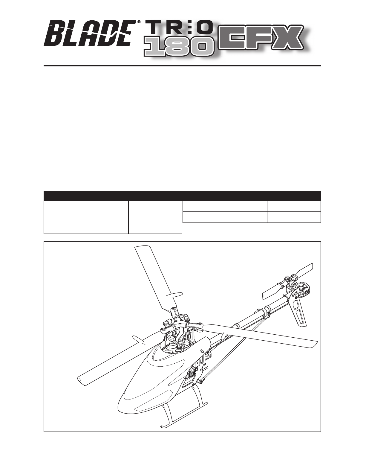
• Blade® Trio 180 CFX
Required Items
• DSM2®/DSMX® compatible transmitter
• 450mAh 3S 11.1V 30C Li-Po Battery
• 3S LiPo compatible battery charger
To receive product updates, special offers and more, register your product at www.bladehelis.com.
First Flight Preparation ..................................................... 4
Flying Checklist ...............................................................4
Transmitter Setup ............................................................ 4
Installing the Flight Battery ..............................................6
Transmitter and Receiver Binding ..................................... 7
Throttle Hold .................................................................... 7
Control Tests .................................................................... 7
Blade Trio 180 CFX Pre-Flight Checklist ........................... 9
Flying the Blade Trio 180 CFX........................................... 9
Low Voltage Cutoff (LVC) ................................................ 10
Gyro Gain Adjustment .................................................... 10
Post-Flight Inspections and Maintenance ....................... 10
Advanced Settings ......................................................... 11
Gain Parameters ............................................................ 11
Entering Gain Adjustment Mode ..................................... 12
Adjusting the Gain Values ............................................... 12
Saving the Gain Adjustments .........................................13
Blade Trio 180 CFX Servo Adjustment ............................13
Entering Servo Adjustment Mode ................................... 13
Adjusting the Servo Neutral Position ..............................14
Swashplate Leveling ...................................................... 14
Saving the Servo Adjustments ........................................ 14
Blade 180 CFX Troubleshooting Guide ............................ 15
Exploded View ............................................................... 16
Replacement Parts ......................................................... 17
Optional Parts ................................................................ 17
Limited Warranty ........................................................... 17
Warranty and Service Contact Information .....................19
FCC Information ............................................................. 19
IC Information ................................................................ 19
Compliance Information for the European Union ............. 19
Page 4
4
EN
Transmitter Setup
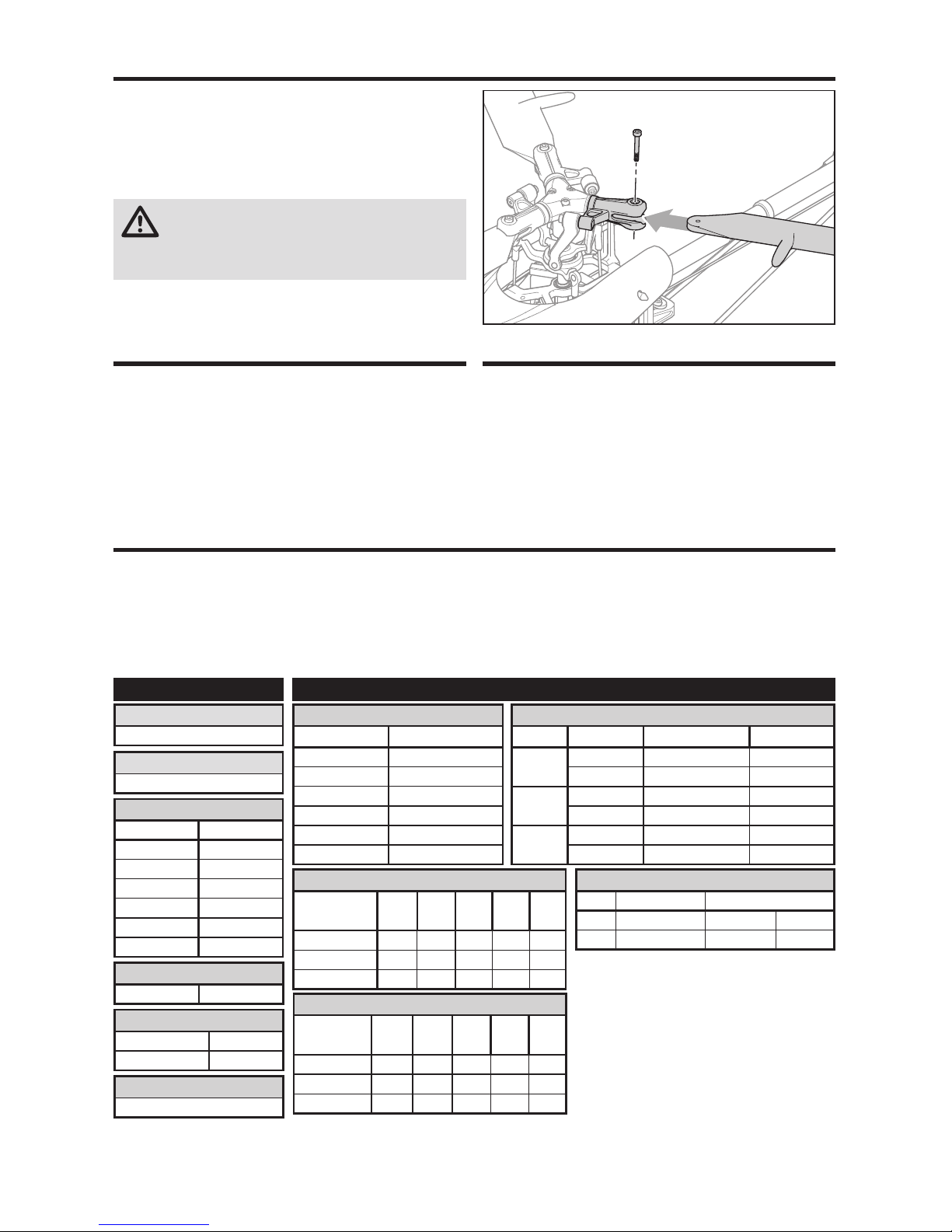
Main Rotor Installation
Program your transmitter before attempting to bind
or fl y the helicopter. Transmitter programming values
are shown below for the Spektrum DX6i, DX7s, DX8,
DX7 (Gen2), DX8 (Gen2), DX9, DX18 and DX20.
The fi les for models using SpektrumTM transmitters with
AirWare™ software are also available for download online
in the Spektrum Community.
Please refer to your transmitter manual for more information on programming throttle hold and normal fl ight mode.
First Flight Preparation
• Remove and inspect contents
• Begin charging the fl ight battery
• Install the fl ight battery in the helicopter
(once it has been fully charged)
• Program your computer transmitter
• Bind your transmitter
• Familiarize yourself with the controls
• Find a suitable area for fl ying
Flying Checklist
❏ Always turn the transmitter on fi rst
❏ Plug the fl ight battery into the lead from the ESC
❏ Allow the receiver and ESC to initialize and arm properly
❏ Fly the model
❏ Land the model
❏ Unplug the fl ight battery from the ESC
❏ Always turn the transmitter off last
Install the main rotor blades as shown using 3, 1.5 mm
socket head screws provided.
Do not overtighten the screws in the blade grips. The
screws should be just tight enough so some friction is felt
when you move the blades, but still loose enough for the
blades to move easily.
CAUTION: Do not use thread locking compound
on the screws or grips. Thread locking compound
will degrade the blade grip material and could cause a
failure of the grip.
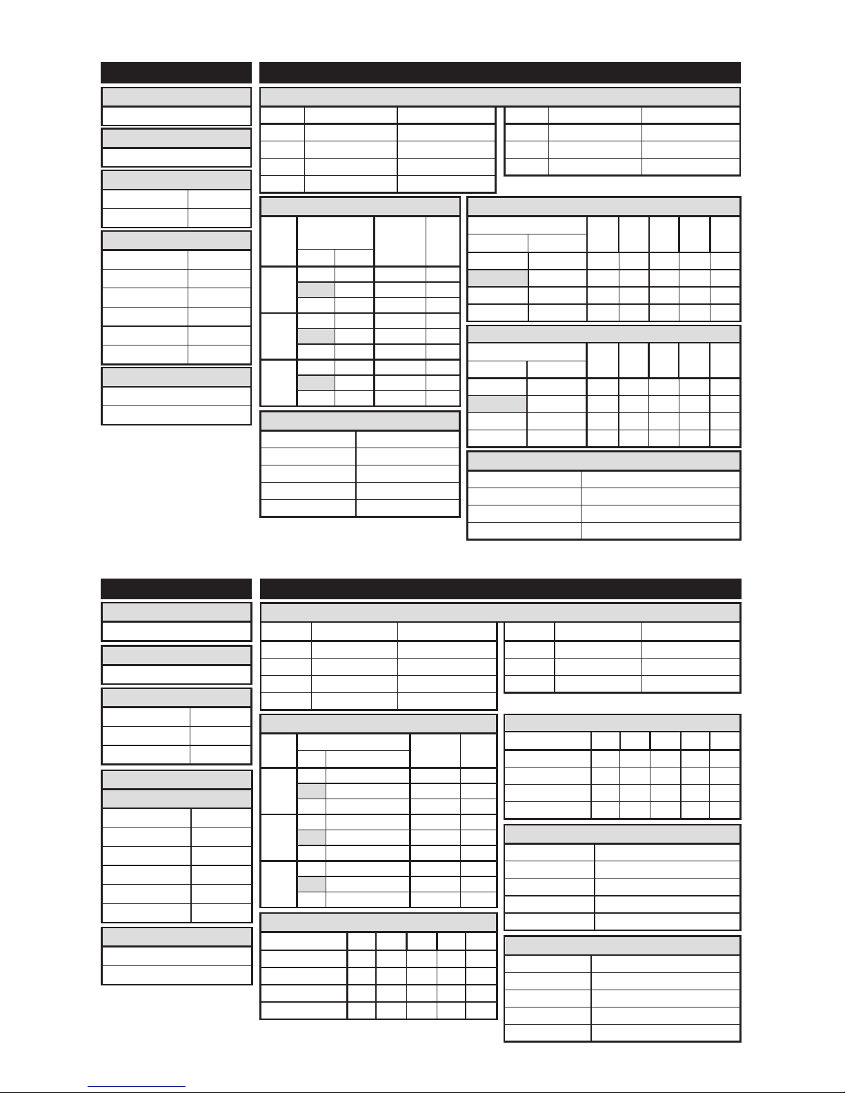
D/R & Expo
Chan Sw Pos D/R Expo
AILE
0 100 +25
1 75 +25
ELEV
0 100 +25
1 75 +25
RUDD
0 100 +25
1 75 +25
Timer
Down Timer 3:00
Switch THR CUT
ADJUST LISTSETUP LIST
DX6i
Throttle Curve
Switch Pos
(F Mode)
Pos 1Pos 2Pos 3Pos 4Pos
5
NORM 0 25 25 25 25
STUNT 100 100 100 100 100
HOLD 0 0 0 0 0
TRAVEL ADJ
Channel Travel
THRO 100/100
AILE 100/100
ELEV 100/100
RUDD 100/100
GYRO 100/100
PITC 100/100
REVERSE
Channel Direction
THRO N
AILE N
ELEV N
RUDD N
GYRO N
PITC R
GYRO
RATE SW-F.MODE
0 50% NORM 0
1 50% STUNT 1
Modulation Type
AUTO DSMX-ENABLE
D/R COMBI
D/R SW AILE
Model Type
HELI
Swash Type
1 servo 90
Pitch Curve
Switch Pos
(F Mode)
Pos 1Pos 2Pos 3Pos 4Pos
5
NORM 30 40 50 75 100
STUNT 0 25 50 75 100
HOLD 0 25 50 75 100
Page 5
5
EN
Model Type
HELI
Swash Type
1 servo Normal
Timer
Mode Count Down
Time 3:00 Tone
Start Throttle Out
Over 25%
Chan Travel Reverse
THR 100/110 Normal
AIL 100/100 Normal
ELE 100/100 Normal
RUD 100/100 Normal
Chan Travel Reverse
GER 100/100 Normal
PIT 100/100 Normal
AX2 100/100 Normal
Servo Setup
FUNCTION LIST
DX7s, DX8
Throttle Curve
Switch Pos (F Mode)
Pt 1 Pt 2 Pt 3 Pt 4 Pt 5DX7s DX8
NN025252525
17575757575
1 2 100 100 100 100 100
HOLD HOLD 0 0 0 0 0
Pitch Curve
Switch Pos (F Mode)
Pt 1 Pt 2 Pt 3 Pt 4 Pt 5
DX7s DX8
N N 30 40 50 75 100
1 0 25 50 75 100
1 2 0 25 50 75 100
HOLD HOLD 0 25 50 75 100
SYSTEM SETUP
F-Mode Setup
Flight Mode F Mode
Hold Hold
SW Select
Trainer AUX 2
F Mode Gear
Gyro INH
Mix INH
Hold INH
Knob INH
Frame Rate
11ms
DSMX
Timer
Mode Count Down
Time 3:00
Start Throttle Out
Over 25%
One Time Inhibit
Gyro
Pos 0 75%
Pos 1 75%
Pos 2 75%
Channel Gear
SW B
Gyro
Normal 75%
Stunt 1 75%
Hold 75%
Channel Gear
SW F Mode
Chan Travel Reverse
THR 100/110 Normal
AIL 100/100 Normal
ELE 100/100 Normal
RUD 100/100 Normal
Chan Travel Reverse
GER 100/100 Normal
PIT 100/100 Normal
AX2 100/100 Normal
Servo Setup
FUNCTION LIST
DX6, DX6e, DX7 (Gen 2), DX8 (Gen 2), DX9, DX18, DX20
SETUP LIST
Throttle Curve
Switch (B) Pos Pt 1 Pt 2 Pt 3 Pt 4 Pt 5
N 025252525
1 75 75 75 75 75
2 100 100 100 100 100
HOLD 00000
Pitch Curve
Switch (B) Pos Pt 1 Pt 2 Pt 3 Pt 4 Pt 5
N 30 40 50 75 100
1 0 25 50 75 100
2 0 25 50 75 100
HOLD 0 25 50 75 100
F-Mode Setup
Switch 1 Switch B
Switch 2 Inhibit
Hold Switch Switch H
Channel Assign
Channel Input Confi g
1 Throttle
2 Aileron
3 Elevator
4 Rudder
5 Gear Switch B
6 Aux 1
Frame Rate
11ms
DSMX
Model Type
HELI
Swash Type
Normal
D/R & Expo
Chan
Switch (F) Pos
D/R ExpoDX6
DX7, 8, 9, 18, 20
AILE
0 0 100/100 0
1 85/85 0
1 2 85/85 0
ELEV
0 0 100/100 0
1 85/85 0
1 2 85/85 0
RUDD
0 0 100/100 0
1 85/85 0
1 2 85/85 0
D/R & Expo
Chan
Switch Pos
(Ail D/R)
D/R ExpoDX7s
DX8
AILE
0 0 100/100 0
1 85/85 0
1 2 85/85 0
ELEV
0 0 100/100 0
1 85/85 0
1 2 85/85 0
RUDD
0 0 100/100 0
1 85/85 0
1 2 85/85 0
Page 6
6
EN
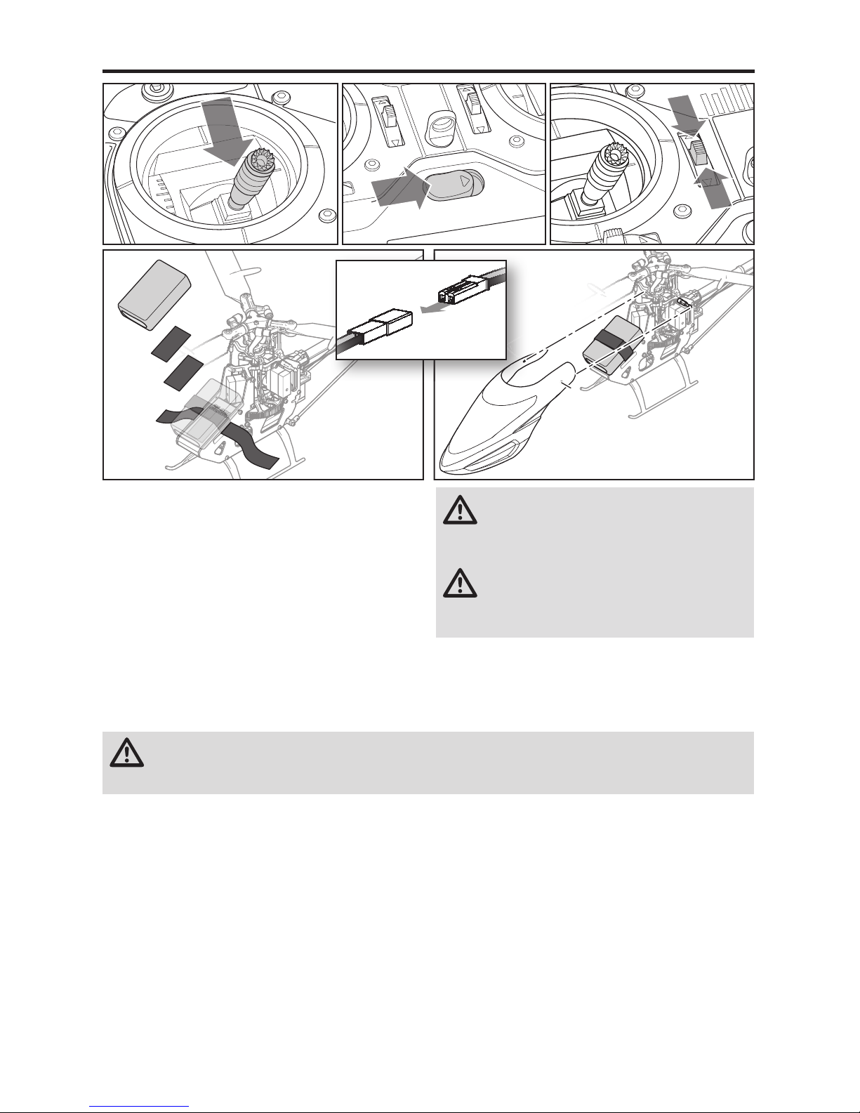
Installing the Flight Battery
CAUTION: Always disconnect the Li-Po battery from the aircraft receiver when not fl ying to avoid over-discharging
the battery. Batteries discharged to a voltage lower than the lowest approved voltage may become damaged,
resulting in loss of performance and potential fi re when batteries are charged.
1. Lower the throttle.
2. Power on the transmitter.
3. Center the throttle trim.
4. To allow the ESC to arm and to keep rotors from initiating at startup, turn on throttle hold and normal fl ight
mode before connecting the fl ight battery.
5. Attach hook material to the helicopter frame and loop
material to the battery.
6. Install the fl ight battery on the helicopter frame. Secure
the fl ight battery with a hook and loop strap. Connect
the battery cable to the ESC.
CAUTION: Always keep the power lead positioned
AWAY from the elevator servo. Failure to do so
could cause the lead to get caught and will result in crash
causing property damage and injury.
CAUTION: Make sure the fl ight battery does not
come in contact with the motor. Failure to do
so will cause the motor, ESC and battery to overheat,
resulting in crash, causing property damage and injury.
7. Do not move the helicopter until the receiver initializes.
The LED on the receiver glows solid when the helicopter
is initialized.
8. The helicopter motor will emit 2 tones, indicating the
ESC is armed.
Page 7

7
EN
Binding Procedure
1. Disconnect the fl ight battery from the helicopter.
2. Refer to the Transmitter Setup Table to correctly set up your transmitter.
3. Lower the throttle and throttle trim to the lowest position.
4. Power off the transmitter and move all switches to the 0 position.
5. Install the bind plug in the bind port extension.
6. Connect the fl ight battery to the ESC. The receiver LED fl ashes, indicating it is in bind mode.
7. Put the transmitter into bind mode while powering on the transmitter.
8. Release the bind button/switch after 2–3 seconds. The helicopter is bound when the LED on the receiver turns solid.
9. Disconnect the fl ight battery and remove the bind plug. Store the bind plug in a convenient place.
NOTICE: Remove the bind plug to prevent the system
from entering bind mode the next time the power is
turned on.
If you encounter problems, obey binding instructions and
refer to transmitter troubleshooting guide for other
instructions. If needed, contact the appropriate Horizon
Product Support offi ce. For a list of compatible DSM transmitters, please visit www.bindnfl y.com.
Binding is the process of programming the receiver to
recognize the GUID (Globally Unique Identifi er) code of a
single specifi c transmitter. You need to ‘bind’ your chosen
Spektrum™ DSM2/DSMX technology equipped aircraft
transmitter to the receiver for proper operation.
Transmitter and Receiver Binding
Throttle Hold
Throttle hold only turns off the motor on an electric helicopter. You must maintain pitch and direction control.
The blades will spin if throttle hold is OFF. For safety, turn
throttle hold ON any time you need to touch the helicopter
or check the direction controls.
Throttle hold is also used to turn off the motor if the
helicopter is out of control, in danger of crashing, or both.
Please refer to your transmitter manual for more
information on programming throttle hold.
Control Tests
Elevator
Aileron
Test the controls prior to the fi rst fl ight to ensure the servos, linkages and parts operate correctly. Turn on Throttle Hold
when doing the control tests.
Rear View
Side View
Side View
Rear View
Page 8

8
EN
Motor Control Test
Place the helicopter outdoors on a clean, fl at and level
surface (concrete or asphalt) free of obstructions. Always
stay clear of moving rotor blades.
1. The motor beeps twice when the helicopter’s ESC
arms properly. Before you continue, confi rm that
TH HOLD is ON.
WARNING: The motor will spin when throttle is
increased while TH HOLD is OFF.
2. Check the swashplate directions to ensure they are
moving in the correct direction. Please refer to the
diagrams above for reference.
WARNING: Stay at least 30 feet (10 meters)
away from the helicopter when the motor is
running. Do not attempt to fl y the helicopter at this time.
3. Set the transmitter to normal fl ight mode. Ensure
the throttle is lowered completely. Turn throttle hold
off at this time. Slowly increase the throttle until the
blades begin to spin. The main blades spin clockwise
when viewing the helicopter from the top. The tail
rotor blades spin counterclockwise when viewing the
helicopter from the right-hand side.
NOTICE: If the main rotor blades are spinning counterclockwise, reduce the throttle to low immediately.
Turn throttle hold on. Disconnect the battery from the
helicopter and reverse any two motor wire connections
to the ESC and repeat the motor control test.
Rudder
Collective Pitch
Side ViewSide View
Page 9

9
EN
Consult local laws and ordinances before choosing a
location to fl y your aircraft.
Select a large, open area away from people and objects.
Your fi rst fl ights should be outdoors in low-wind conditions.
Always stay at least 30 feet (10 meters) away from the
helicopter when it is fl ying.
The Blade 180 CFX is intended to be fl own outdoors or
inside a large gymnasium.
Takeoff
Increase the throttle to quickly establish a hover at least
24” (0.6 meter) high, outside of ground effect.
CAUTION: Do not give any aileron, elevator
or rudder commands before takeoff or the
helicopter may crash during takeoff.
Flying
The helicopter lifts off the ground when the rotor head
reaches a suitable speed. Establish a low-level hover
outside of ground effect to verify proper operation of your
helicopter. You must not set any trim; the fl ybarless design
of the Blade 180 CFX renders trim unnecessary. Setting
trim or sub-trim can cause an unwanted drift or rotation of
the helicopter.
First fl ights should be performed in normal mode and low
cyclic and rudder dual rates until you are familiar with the
fl ying manner of the Blade 180 CFX. Discover the rates that
fi t your fl ying style.
CAUTION: Always try to fl y the helicopter with
your back to the sun and the wind to prevent
loss of fl ight control.
Landing
Establish a low level hover. Gently lower the throttle until
the helicopter lands. Do not give any aileron, elevator or
rudder commands when the helicopter touches down.
Flight Modes
No rmal Mode: This mode has a low head speed and
limited negative collective pitch available. It should be
used for takeoff, landing and very mild upright fl ight.
Never attempt to fl y inverted in Normal Mode.
St unt 1 Mode: This mode has a constant moderate head
speed and full range of rotor collective pitch available.
St unt 2 Mode: This mode has a constant high head speed
and full range of rotor collective pitch available.
DX6i and DX7s users: Your transmitter is limited to 2
fl ight modes. The transmitter setup table values show
how to program your transmitter for Normal Mode and
Stunt 2 Mode as your available fl ight modes. If you would
prefer Stunt 1 Mode over Stunt 2 Mode, change the STUNT
values of the Throttle Curve to 85%.
When the helicopter is in stunt mode:
• The rotor head speed is constant.
• The main rotor will increase negative pitch as the throttle/
collective stick is moved from the middle stick position to
the low stick position. Negative pitch allows the helicopter
to fl y upside down and perform aerobatics.
Change between stunt and normal modes in a hover with
the throttle near the hovering stick position.
The helicopter may go up or down when you change
between modes due to the difference in the throttle and
pitch curves.
If the cyclic control is too slow or too fast, adjust the transmitter dual rates, expo or throttle curve to fi t your liking.
For advanced AS3X settings please go to
Bladehelis.com and refer to the 180 CFX page.
Flying the Blade Trio 180 CFX
❏ Check all screws to ensure that they are tight
❏ Check main and tail blades to ensure they are not
damaged
❏ Check all links to make sure they move freely, but do
not pop off easily
❏ Check that fl ight battery and transmitter battery are
fully charged
❏ Check all wires to ensure that they are not cut,
pinched, or chaffed and are properly secured
❏ Check all wire connections
❏ Check gears to make sure no teeth are missing
❏ Do a complete control test
❏ Check that the servos are functioning properly
❏ Check to make sure the fl ight battery is properly secured
❏ Check to make sure the receiver is properly secured
Blade Trio 180 CFX Pre-Flight Checklist
Page 10

10
EN
Gyro Gain Adjustment
If the tail wags or oscillates, lower the gain on the gyro.
On your transmitter’s gyro menu, decrease the gyro gain
values a small amount until the helicopter is stable within a
particular fl ight mode.
If the tail is drifting while hovering, increase the gain on the
gyro. On your transmitter, increase the gyro gain values a
small amount at a time until the tail starts to wag/oscillate.
Afterwards, reduce the gain until the tail stops wagging/
oscillating within a particular fl ight mode.
Low Voltage Cuto (LVC)
Once the battery reaches 9V under load, the ESC will
continuously lower power supplied to the motor until
complete shutdown occurs. This helps prevent overdischarge of the Li-Po battery. Land immediately once the
ESC activates LVC. Continuing to fl y after LVC can damage
the battery, cause a crash or both. Crash damage and
batteries damaged due to over-discharge are not covered
under warranty.
Repeatedly fl ying the helicopter until LVC activates will
damage the helicopter battery.
Disconnect and remove the Li-Po battery from the aircraft
after use to prevent trickle discharge. During storage, make
sure the battery charge does not fall below 3V per cell.
Post-Flight Inspections and Maintenance
Ball Links
Make sure the plastic ball link holds the control ball, but is not tight (binding) on the ball.
When a link is too loose on the ball, it can separate from the ball during fl ight and cause a
crash. Replace worn ball links before they fail.
Cleaning
Make sure the battery is not connected before cleaning. Remove dust and debris with a
soft brush or a dry lint-free cloth.
Bearings Replace bearings when they become notchy (sticky in places when turning) or draggy.
Wiring
Make sure the wiring does not contact moving parts. Replace damaged wiring and loose
connectors.
Fasteners
Make sure there are no loose screws, other fasteners or connectors. Do not over tighten
metal screws in plastic parts. Tighten screw so parts are mated together, then turn screw
only 1/8th of a turn more.
Rotors
Make sure there is no damage to rotor blades and other parts which move at high speed.
Damage to these parts includes cracks, burrs, chips or scratches. Replace damaged parts
before fl ying.
Gyro
Make sure the receiver is securely attached to the frame. Replace the double-sided tape
when necessary. The helicopter will crash if the receiver separates from the helicopter
frame.
Page 11

11
EN
Advanced Settings
WARNING: To ensure your safety, always disconnect the motor wires from the ESC before performing the
following steps. After you have completed the adjustments, reconnect the motor wires to the ESC before at-
tempting to fl y the model.
The 180 CFX default settings are appropriate for most users. We recommend fl ying with the default parameters before
making any adjustments.
Transmitter Channel Input Confi guration Reversing Setup
DX6, DX6i, DX6e No setup required
DX7s, DX7 (G2), DX8, DX8 (G2), DX9, DX18, DX20 7(AUX2): Switch I AX2 = Reverse
Gain Parameters
1. Cyclic P Gain Adjustment (Default 100%)
Higher gain will result in greater stability. Setting the gain
too high may result in random twitches if your model has
an excessive level of vibration. High frequency oscillations may also occur if the gain is set too high.
Lower gain will result in less stability. Too low
of a value may result in a less stable model particularly
outdoors in winds.
If you are located at a higher altitude or in a warmer
climate, higher gains may be benefi cial—the opposite
is true for lower altitude or colder climates.
2. Cyclic I Gain Adjustment (Default 100%)
Higher gain will result in the model remaining still, but
may cause low frequency oscillations if increased too far.
Lower gain will result in the model drifting slowly.
If you are located at a higher altitude or in a warmer
climate, higher gains may be benefi cial—the opposite
is true for lower altitude or colder climates.
3. Cyclic D Gain Adjustment (Default 100%)
Higher gain will improve the response rate of your
inputs. If the gain is raised too much, high frequency
oscillations may occur.
Lower gain will slow down the response to inputs.
4. Cyclic Response (Default 100%)
Higher cyclic response will result in a more
aggressive cyclic response.
Lower cyclic response will result in a less
aggressive cyclic response.
5. Tailrotor P Gain Adjustment (Default 100%)
Higher gain will result in greater stability. Setting the gain
too high may result in random twitches if your model has
an excessive level of vibration. High frequency oscillations may also occur if the gain is set too high.
Lower gain may result in a decrease in stability. Too low
of a value may result in a less stable model particularly
outdoors in winds.
If you are located at a higher altitude or in a warmer
climate, higher gains may be benefi cial—the opposite
is true for lower altitude or colder climates.
6. Tailrotor I Gain Adjustment (Default 100%)
Higher gain results in the tail remaining still. If the gain
is raised too far, low speed oscillations may occur.
Lower gain will result in the tail drifting in fl ight over time.
If you are located at a higher altitude or in a warmer
climate, higher gains may be benefi cial—the opposite
is true for lower altitude or colder climates.
7. Tailrotor D Gain Adjustment (Default 100%)
Higher gain will improve the response rate
to your inputs. If raised too far, high frequency oscilla-
tions may occur.
Lower gain will slow down the response to inputs, but
will not have an effect on stability.
Before accessing the Gain Parameter Adjustment or Servo Adjustment, you must assign channel 7 (AUX2) to the bind
switch on the transmitter.
Page 12

12
EN
Entering Gain Adjustment Mode
DX6, DX6e and DX6i Users:
1. Lower the throttle stick to the lowest position.
2. Power ON the transmitter.
3. Install the fl ight battery on the helicopter frame, securing it with the hook and loop strap.
4. Connect the battery connector to the ESC.
5. Before initialization is complete, move and hold both
transmitter sticks to the bottom right corner as shown.
6. When the servos move, you have entered Gain Adjustment Mode.
7. Release the sticks and proceed to Adjusting the Gain
Values to make any desired changes.
DX7s, DX7 (G2), DX8, DX8 (G2), DX9, DX18 and DX20 Users:
1. Lower the throttle stick to the lowest position.
2. Power ON the transmitter.
3. Install the fl ight battery on the helicopter frame, securing it with the hook and loop strap.
4. Connect the battery connector to the ESC.
5. Place the helicopter on a fl at surface and leave it still
until the orange receiver LED glows solid, indicating
initialization is complete.
6. Move and hold both transmitter sticks to the bottom
right corner as shown.
7. Press and hold the bind/panic switch until the swash
servos move.
8. Release the sticks and the bind/panic switch. The
model is now in Gain Adjustment Mode.
9. Proceed to Adjusting the Gain Values to make any
desired changes.
Adjusting the Gain Values
If you are using a Spektrum™ telemetry-enabled transmitter, the gain adjustments can be viewed on the Flight Log
screen. Refer to your transmitter instructions to locate this
screen. The gain parameter currently selected will fl ash
on the transmitter screen. If you are not using a Spektrum
telemetry-enabled transmitter, the parameter and gain
values are indicated by the position of the swashplate on
the helicopter.
Once you have entered Gain Adjustment Mode, you can
move the cyclic stick right and left to select the gain parameter you would like to adjust. Moving the stick right will
select the next parameter. Moving the stick left will select
the previous parameter.
The selected gain parameter is indicated on the Flight Log
screen and by the lean of the swashplate on the roll axis.
Parameter #
Display
location
Swash Position Page #
1 A 100% to the Left 1
2 B 50% to the Left 1
3 L 25% to the Left 1
4 R Swashplate Level 1
5 A 25% to the Right 2
6 B 50% to the Right 2
7 L 100% to the Right 2
P age number
1 = Cyclic gains
2 = Tail rotor gains
Gain parameter
selected
Gain value
display location
Flight Log Screen
Page 13

13
EN
Entering Servo Adjustment Mode
DX6, DX6e and DX6i Users:
1. Lower the throttle stick to the lowest position.
2. Power ON the transmitter.
3. Install the fl ight battery on the helicopter frame,
securing it with the hook and loop strap.
4. Connect the battery connector to the ESC.
5. Before initialization is complete, hold the left stick to
the bottom left corner and the right stick to the bottom
right corner as shown.
6. When the swashplate servos move, you have entered
Servo Adjustment Mode.
7. Release the sticks and proceed to Adjusting the Servo
Neutral Position to make any desired changes.
DX7s, DX7 (G2), DX8, DX8 (G2), DX9, DX18 and DX20 Users:
1. Lower the throttle stick to the lowest position.
2. Power ON the transmitter.
3. Install the fl ight battery on the helicopter frame,
securing it with the hook and loop strap.
4. Connect the battery connector to the ESC.
5. Place the helicopter on a fl at surface and leave it still
until the orange receiver LED glows solid, indicating
initialization is complete.
6. Hold the left stick to the bottom left corner and the
right stick to the bottom right corner as shown.
7. Hold the bind/panic switch until the swash servos move.
8. Release the sticks and the bind/panic switch. The
model is now in Servo Adjustment Mode.
9. Proceed to Adjusting the Servo Neutral Position to
make any desired changes.
The current gain value for the selected parameter is indicated
on the Flight Log screen and by the angle of the swashplate
(forward or backward) as shown in the table below.
Move the cyclic stick forward or backward to adjust the
gain value. Moving the stick forward will increase the gain
value. Moving the stick backward will decrease the gain
value.
It is always best to adjust one gain at a time. Make small
adjustments (5% or less) and test fl y the model to evaluate
the adjustments that were made.
If you would like to reset the current gain value to the
default value of 100%, move and hold the rudder stick full
right for 1 second. The swash will level on the pitch axis,
indicating a 100% gain setting.
Saving the Gain Adjustments
DX6, DX6e and DX6i Users:
1. Lower the throttle stick to the lowest position and
release the sticks.
2. Move the tail rotor stick to the left and hold until the
servos move.
3. Release the tail rotor stick to save the gain adjustments.
4. Reconnect the main drive motor to the ESC. Your model
is now ready for fl ight.
DX7s, DX7 (G2), DX8, DX8 (G2), DX9, DX18 and DX20 Users:
1. Lower the throttle stick to the lowest position and
release the sticks.
2. Press and hold switch I until the swash servos move.
3. Release switch I to save the gain adjustments.
4. Reconnect the main drive motor to the ESC. Your model
is now ready for fl ight.
Swash Position Gain Value
Full backward 0%
50% backward 50%
Level forward and backward 100%
50% forward 150%
Full forward 200%
Blade Trio 180 CFX Servo Adjustment
Your Blade 180 CFX was setup at the factory and test fl own. The servo adjustment steps are usually only necessary in
special circumstances, such as after a crash or if a servo or linkage is replaced.
WARNING: To ensure your safety, always disconnect the motor wires from the ESC before performing the
following steps. After you have completed the adjustments, reconnect the motor wires to the ESC before
attempting to fl y the model.
Page 14

14
EN
Adjusting the Servo Neutral Position
With the model in Servo Adjustment Mode, the control stick
and gyro inputs are disabled and the servos are held in the
neutral position. Check the position of the servo arms to
see if they are perpendicular to the servos.
• If the arms are perpendicular to the servos, no adjustment is necessary.
Exit Servo Adjustment Mode.
• If one or more servo arm is not perpendicular to the
servos, continue the servo adjustment process.
While watching the swashplate servos, apply right cyclic
and release. One of the servos will jump, indicating which
servo is selected. Press right cyclic and release until the
servo that needs to be adjusted is selected.
Once the servo you wish to adjust is selected, move the
cyclic stick forward or backward to adjust the servo neutral
position in the desired direction.
If you would like to reset the current servo to the default
neutral position, hold the rudder stick full right for 1
second.
The range of adjustment is limited. If you are unable to
adjust the servo arm to be perpendicular to the servo, you
must reset the servo to the default neutral position, remove
the servo arm and place it back onto the servo as close to
perpendicular as possible. You may then adjust the servo
neutral position using the forward/backward cyclic stick.
Swashplate Leveling
Before saving your adjustments and exiting servo adjustment mode, verify the swashplate is level and both main
rotor blades are at 0 degrees.
If they are not, make linkage adjustments as necessary.
Saving the Servo Adjustments
DX6, DX6e and DX6i Users:
1. Lower the throttle stick to the lowest position and
release the sticks.
2. Move the tail rotor stick to the left and hold until the
servos move.
3. Release the tail rotor stick to save the servo adjustments.
4. Reconnect the main drive motor to the ESC. Your model
is now ready for fl ight.
DX7s, DX7 (G2), DX8, DX8 (G2), DX9, DX18 and DX20 Users:
1. Lower the throttle stick to the lowest position and
release the sticks.
2. Press and hold switch I until the swash servos move.
3. Release switch I to save the servo adjustments.
4. Reconnect the main drive motor to the ESC. Your model
is now ready for fl ight.
All of the settings are stored internally, so your adjustments
will be maintained each time you initialize the model.
Page 15

15
EN
Blade 180 CFX Troubleshooting Guide
Problem Possible Cause Solution
Helicopter will not bind
to the transmitter (during binding)
Low fl ight battery or transmitter battery voltage
Fully charge or replace the fl ight battery and/or transmitter batteries
The receiver is not in bind mode
Make sure the bind plug is connected to the receiver
bind port extension
Transmitter is not in bind mode
Refer to your transmitter's instruction manual for binding
instructions
Transmitter too close to the helicopter
during the binding process
Power off the transmitter. Move the transmitter to a
larger distance from the helicopter. Disconnect and
reconnect the fl ight battery to the helicopter and follow
binding instructions
Helicopter will not
link to the transmitter
(after binding)
Helicopter is bound to a different model
memory (ModelMatch™ radios only)
Disconnect the fl ight battery. Select the correct model
memory on the transmitter. Reconnect the fl ight battery
Flight battery/Transmitter battery
charge is too low
Replace or recharge batteries
The receiver will not
initialize
The helicopter was moved during
initialization
Lay the helicopter on its side during initialization if windy
The transmitter is powered off Power on the transmitter
Controls are not centered
Center elevator, aileron and rudder controls. Make sure
the throttle is at idle
Helicopter will not
respond to the throttle
but responds to other
controls
Throttle not at idle and/or throttle trim
is too high
Lower the throttle stick and throttle trim to the lowest
settings
The transmitter fl ight mode is not in
normal mode
Set the fl ight mode to normal mode
Throttle hold is on Make sure throttle hold is off
The motor is not connected to the ESC
or the motor wires are damaged
Connect the motor wires to the ESC and check motor
wires for damage
Flight battery charge is too low Replace or recharge fl ight battery
Throttle channel is reversed
Power down helicopter. Reverse the throttle channel on
the transmitter
Helicopter power is
lacking
Flight battery has low voltage Fully charge the fl ight battery
Flight battery is old or damaged Replace the fl ight battery
Flight battery cells are unbalanced
Fully charge the fl ight battery, allowing the charger time
to balance the cells
Excessive current is being drawn
through the BEC
Check all servos and the helicopter motor for damage
Helicopter will not
lift off
Main rotor head is not spinning in the
correct direction
Make sure the main rotor head is spinning clockwise.
Refer to motor control test
Transmitter settings are not correct Check throttle and pitch curve settings
Flight battery has low voltage Fully charge the fl ight battery
Main rotor blades are installed backwards
Install the main rotor blades with the thicker side as the
leading edge
The helicopter tail
spins out of control
Rudder control and/or sensor direction
reversed
Make sure the rudder control and the rudder sensor are
operating in the correct direction
Tail servo is damaged Check the rudder servo for damage and replace if necessary
Inadequate control arm throw
Check the rudder control arm for adequate travel and
adjust if necessary
The helicopter wobbles in fl ight
Headspeed is too low
Increase the helicopter's head speed via your transmitter
settings and/or using a freshly charged fl ight pack
Dampers are worn Replace the main rotor head dampers
Page 16

16
EN
24
18
17
30
28
29
29
27
26
34
15
25
23
25
25
16
16
39
39
15
14
33
13
13
18
19
19
19
19
28
28
28
29
44
Exploded View
36
1
38
37
38
39
32
32
31
40
41
3
37
6
4
5
44
44
44
6
2
45
9
8
11
42
12
35
10
7
7
Page 17

17
EN
# Part # Description
1 BLH3407 Main Shaft Set: 180 CFX
2 BLH3408 Main Gear: 180 CFX
3 BLH3410 Servo Control Linkage Set: 180 CFX
4 BLH3411 Main Bearing Block Set: 180 CFX
5 BLH3412 Anti-Rotation Bracket: 180 CFX
6 BLH3413 Carbon Fiber Main Frame: 180 CFX
7 BLH3414 Body Post Set: 180 CFX
8 BLH3415 Battery Tray: 180 CFX
9 BLH3416 Motor Mount: 180 CFX
10 BLH3417 Brushless Main Motor: 180 CFX
11 BLH3418 Bottom Plate: 180 CFX
12 BLH3419 Landing Gear: 180 CFX
13 BLH3420 Front Tail Boom Case: 180 CFX
14 BLH3421 Tail Pinion Gear/Shaft: 180 CFX
15 BLH3422 Bevel Gear: 180 CFX
16 BLH3423 Torque Tube Gear: 180 CFX
17 BLH3424 Tail Boom (2): 180 CFX
18 BLH3425 Torque Tube (2): 180 CFX
19 BLH3426 Boom Support Set: 180 CFX
20 BLH3427 Tail Pushrod (2): 180 CFX
21 BLH3428 Tail Pushrod Guide Set: 180 CFX
22 BLH3429 Tail Boom Clamp: 180 CFX
23 BLH3430 Vertical Fin: 180 CFX
# Part # Description
24 BLH3431 Tail Case Set: 180 CFX
25 BLH3432 Tail Shaft and Hub: 180 CFX
26 BLH3433 Tail Pitch Bellcrank: 180 CFX
27 BLH3434 Tail Pitch Slider: 180 CFX
28 BLH3435 Tail Grip Set: 180 CFX
29 BLH3436 Tail Grip Bearing Set: 180 CFX
30 BLH3437 Tail Blade Set: 180 CFX
31 BLH3438 2.5x6x2.8mm Thrust Bearing: 180 CFX
32 BLH3439 2.5x6x1.8mm Radial Bearing: 180 CFX
33 BLH3440 5x8x2mm Radial Bearing: 180 CFX
34 BLH3441 2.5x6x2.6 Flanged Bearing: 180 CFX
35 BLH3442 Castle Creations 15A Blade ESC
36 BLH3751 150mm Main Blades (3): Trio 180 CFX
37 BLH3752 3-Blade Head Block: Trio 180 CFX
38 BLH3753 Feathering Spindle Set (3): Trio 180 CFX
39 BLH3754 Main Blade Grips (3): Trio 180 CFX
40 BLH3755 Flybarless Follower Arms (3): Trio 180 CFX
41 BLH3756 Swashplate: Trio 180 CFX
42 BLH3758 Stock Canopy: Trio 180 CFX
43
EFLRDS76TJ
7.6g Sub-Micro Digital Tail Servo JST
44
SPMSH2065
7.6g Sub-Micro Digital Metal Gear Servo JST
45 BLH3759 Blade Replacement Receiver: Trio 180
Part # Description
EFLB4503SJ30 450mAh 3S 11.1V 30C LiPo, 18AWG JST
BLH3402C Carbon Fiber Main Blades: 180 CFX
BLH3409 Stock Canopy: 180 CFX
BLH3409A Option Canopy: 180 CFX
BLH3431A Aluminum Tail Case Set: 180 CFX
BLH3433A Aluminum Tail Pitch Bellcrank: 180 CFX
BLH3434A Tail Pitch Slider Aluminum: 180 CFX
DYNC2005 Prophet Sport Li-Po 35W AC Charger
Part # Description
DX6i DSMX 6-Channel Transmitter Only
DX6 DSMX 6-Channel Transmitter Only
DX7s DSMX 7-Channel Transmitter Only
DX8 DSMX 8-Channel Transmitter Only
DX9 DSMX 9-Channel Transmitter Only
DX18 DSMX 18-Channel Transmitter Only
DX20 DSMX 20-Channel Transmitter Only
Replacement Parts
Optional Parts
What this Warranty Covers
Horizon Hobby, LLC, (Horizon) warrants to the original purchaser
that the product purchased (the “Product”) will be free from
defects in materials and workmanship at the date of purchase.
What is Not Covered
This warranty is not transferable and does not cover (i) cosmetic
damage, (ii) damage due to acts of God, accident, misuse,
abuse, negligence, commercial use, or due to improper use,
installation, operation or maintenance, (iii) modi cation of or to
any part of the Product, (iv) attempted service by anyone other
than a Horizon Hobby authorized service center, (v) Product not
purchased from an authorized Horizon dealer, (vi) Product not
compliant with applicable technical regulations, or (vii) use that
violates any applicable laws, rules, or regulations.
OTHER THAN THE EXPRESS WARRANTY ABOVE, HORIZON
MAKES NO OTHER WARRANTY OR REPRESENTATION, AND
HEREBY DISCLAIMS ANY AND ALL IMPLIED WARRANTIES,
INCLUDING, WITHOUT LIMITATION, THE IMPLIED
WARRANTIES OF NON-INFRINGEMENT, MERCHANTABILITY
AND FITNESS FOR A PARTICULAR PURPOSE. THE
PURCHASER ACKNOWLEDGES THAT THEY ALONE HAVE
DETERMINED THAT THE PRODUCT WILL SUITABLY MEET THE
REQUIREMENTS OF THE PURCHASER’S INTENDED USE.
Purchaser’s Remedy
Horizon’s sole obligation and purchaser’s sole and exclusive
remedy shall be that Horizon will, at its option, either (i)
service, or (ii) replace, any Product determined by Horizon
to be defective. Horizon reserves the right to inspect any
Limited Warranty
Page 18

18
EN
and all Product(s) involved in a warranty claim. Service or
replacement decisions are at the sole discretion of Horizon.
Proof of purchase is required for all warranty claims.
SERVICE OR REPLACEMENT AS PROVIDED UNDER THIS
WARRANTY IS THE PURCHASER’S SOLE AND EXCLUSIVE
REMEDY.
Limitation of Liability
HORIZON SHALL NOT BE LIABLE FOR SPECIAL, INDIRECT,
INCIDENTAL OR CONSEQUENTIAL DAMAGES, LOSS OF
PROFITS OR PRODUCTION OR COMMERCIAL LOSS IN ANY
WAY, REGARDLESS OF WHETHER SUCH CLAIM IS BASED
IN CONTRACT, WARRANTY, TORT, NEGLIGENCE, STRICT
LIABILITY OR ANY OTHER THEORY OF LIABILITY, EVEN IF
HORIZON HAS BEEN ADVISED OF THE POSSIBILITY OF SUCH
DAMAGES. Further, in no event shall the liability of Horizon
exceed the individual price of the Product on which liability
is asserted. As Horizon has no control over use, setup,
nal assembly, modi cation or misuse, no liability shall be
assumed nor accepted for any resulting damage or injury.
By the act of use, setup or assembly, the user accepts all
resulting liability. If you as the purchaser or user are not
prepared to accept the liability associated with the use of
the Product, purchaser is advised to return the Product
immediately in new and unused condition to the place of
purchase.
Law
These terms are governed by Illinois law (without regard to
con ict of law principals). This warranty gives you speci c
legal rights, and you may also have other rights which vary
from state to state. Horizon reserves the right to change or
modify this warranty at any time without notice.
WARRANTY SERVICES
Questions, Assistance, and Services
Your local hobby store and/or place of purchase cannot
provide warranty support or service. Once assembly, setup
or use of the Product has been started, you must contact
your local distributor or Horizon directly. This will enable
Horizon to better answer your questions and service you in
the event that you may need any assistance. For questions
or assistance, please visit our website at www.horizonhobby.
com, submit a Product Support Inquiry, or call the toll free
telephone number referenced in the Warranty and Service
Contact Information section to speak with a Product Support
representative.
Inspection or Services
If this Product needs to be inspected or serviced and is
compliant in the country you live and use the Product in,
please use the Horizon Online Service Request submission
process found on our website or call Horizon to obtain a
Return Merchandise Authorization (RMA) number. Pack the
Product securely using a shipping carton. Please note that
original boxes may be included, but are not designed to
withstand the rigors of shipping without additional protection.
Ship via a carrier that provides tracking and insurance for
lost or damaged parcels, as Horizon is not responsible for
merchandise until it arrives and is accepted at our facility.
An Online Service Request is available at http://www.
horizonhobby.com/content/_service-center_render-servicecenter. If you do not have internet access, please contact
Horizon Product Support to obtain a RMA number along with
instructions for submitting your product for service. When
calling Horizon, you will be asked to provide your complete
name, street address, email address and phone number
where you can be reached during business hours. When
sending product into Horizon, please include your RMA
number, a list of the included items, and a brief summary
of the problem. A copy of your original sales receipt must
be included for warranty consideration. Be sure your name,
address, and RMA number are clearly written on the outside
of the shipping carton.
NOTICE: Do not ship Li-Po batteries to Horizon. If you
have any issue with a Li-Po battery, please contact the
appropriate Horizon Product Support of ce.
Warranty Requirements
For Warranty consideration, you must include your original
sales receipt verifying the proof-of-purchase date. Provided
warranty conditions have been met, your Product will be
serviced or replaced free of charge. Service or replacement
decisions are at the sole discretion of Horizon.
Non-Warranty Service
Should your service not be covered by warranty, service
will be completed and payment will be required without
noti cation or estimate of the expense unless the expense
exceeds 50% of the retail purchase cost. By submitting
the item for service you are agreeing to payment of the
service without noti cation. Service estimates are available
upon request. You must include this request with your item
submitted for service. Non-warranty service estimates will
be billed a minimum of ½ hour of labor. In addition you will
be billed for return freight. Horizon accepts money orders
and cashier’s checks, as well as Visa, MasterCard, American
Express, and Discover cards. By submitting any item to
Horizon for service, you are agreeing to Horizon’s Terms and
Conditions found on our website http://www.horizonhobby.
com/content/_service-center_render-service-center.
ATTENTION: Horizon service is limited to Product
compliant in the country of use and ownership.
If received, a non-compliant Product will not be
serviced. Further, the sender will be responsible
for arranging return shipment of the un-serviced
Product, through a carrier of the sender’s choice
and at the sender’s expense. Horizon will hold
non-compliant Product for a period of 60 days from
notifi cation, after which it will be discarded. 10/15
Page 19

19
EN
Warranty and Service Contact Information
Compliance Information for the European Union
This equipment has been tested and found to comply with
the limits for Part 15 of the FCC rules. These limits are
designed to provide reasonable protection against harmful
interference in a residential installation. This equipment
generates uses and can radiate radio frequency energy and,
if not installed and used in accordance with the instructions,
may cause harmful interference to radio communications.
However, there is no guarantee that interference will not
occur in a particular installation. If this equipment does
cause harmful interference to radio or television reception,
which can be determined by turning the equipment off and
on, the user is encouraged to try to correct the interference
by one or more of the following measures:
• Reorient or relocate the receiving antenna.
• Increase the separation between the equipment and
receiver.
• Connect the equipment to an outlet on a circuit different
from that to which the receiver is connected.
This device complies with part 15 of the FCC rules.
Operation is subject to the following two conditions: (1) This
device may not cause harmful interference, and (2) this
device must accept any interference received, including
interference that may cause undesired operation.
NOTICE: Modifi cations to this product will void the user’s
authority to operate this equipment.
FCC Information
IC Information
This device complies with Industry Canada licence-exempt
RSS standard(s). Operation is subject to the following two
conditions:
(1) this device may not cause interference, and (2) this
device must accept any interference, including interference
that may cause undesired operation of the device.”
EU Compliance Statement: BLH3750
Horizon Hobby, LLC hereby declares that this product is in compliance with the essential requirements and
other relevant provisions of the RED Directive.
A copy of the EU Declaration of Conformity is available online at:
http://www.horizonhobby.com/content/support-render-compliance.
Instructions for disposal of WEEE by users in the European Union
This product must not be disposed of with other waste. Instead, it is the user’s responsibility to dispose
of their waste equipment by handing it over to a designated collections point for the recycling of waste
electrical and electronic equipment. The separate collection and recycling of your waste equipment at
the time of disposal will help to conserve natural resources and make sure that it is recycled in a manner
that protects human health and the environment. For more information about where you can drop off your
waste equipment for recycling, please contact your local city offi ce, your household waste disposal service
or where you purchased the product.
Country of Pur-
chase
Horizon Hobby Contact Information Address
United States
of America
Horizon Service Center
(Repairs and Repair Requests)
servicecenter.horizonhobby.com/
RequestForm/
4105 Fieldstone Rd
Champaign, Illinois, 61822 USA
Horizon Product Support
(Product Technical Assistance)
productsupport@horizonhobby.com
877-504-0233
Sales
websales@horizonhobby.com
800-338-4639
European Union
Horizon Technischer Service service@horizonhobby.de
Hanskampring 9
D 22885 Barsbüttel, Germany
Sales: Horizon Hobby GmbH +49 (0) 4121 2655 100
Page 20

72
IT
©2017 Horizon Hobby, LLC.
Blade, E-fl ite, Prophet, AS3X, DSM, DSM2, DSMX, AirWare, ModelMatch, BNF, the BNF logo
and the Horizon Hobby logo are trademarks or registered trademarks of Horizon Hobby, LLC.
The Spektrum trademark is used with permission of Bachmann Industries, Inc.
All other trademarks, service marks or logos are property of their respective owners.
Patents pending.
Created 11/16 51452 BLH3750
 Loading...