

Page 1

AH-64 Apache
™
Instruction Manual
Bedienungsanleitung
Manuel d’utilisation
Manuale di Istruzioni
RTF
Page 2
2
EN
WARNING: Read the ENTIRE instruction manual to become familiar with the features of the product before
operating. Failure to operate the product correctly can result in damage to the product, personal property and
cause serious injury.
This is a sophisticated hobby product. It must be operated with caution and common sense and requires some basic
mechanical ability. Failure to operate this Product in a safe and responsible manner could result in injury or damage
to the product or other property. This product is not intended for use by children without direct adult supervision. Do
not use with incompatible components or alter this product in any way outside of the instructions provided by Horizon
Hobby, LLC. This manual contains instructions for safety, operation and maintenance. It is essential to read and follow
all the instructions and warnings in the manual, prior to assembly, setup or use, in order to operate correctly and avoid
damage or serious injury.
• Always keep a safe distance in all directions around
your model to avoid collisions or injury. This model is
controlled by a radio signal subject to interference from
many sources outside your control. Interference can
cause momentary loss of control.
• Always operate your model in open spaces away from
full-size vehicles, traffi c and people.
• Always carefully follow the directions and warnings for
this and any optional support equipment
(chargers, rechargeable battery packs, etc.).
• Always keep all chemicals, small parts and anything
electrical out of the reach of children.
• Always avoid water exposure to all equipment not
specifi cally designed and protected for this purpose.
Moisture causes damage to electronics.
• Never place any portion of the model in your mouth as it
could cause serious injury or even death.
• Never operate your model with low transmitter
batteries.
• Always keep aircraft in sight and under control.
• Always move the throttle fully down at rotor strike.
• Always use fully charged batteries.
• Always keep transmitter powered on while aircraft is
powered.
• Always remove batteries before disassembly.
• Always keep moving parts clean.
• Always keep parts dry.
• Always let parts cool after use before touching.
• Always remove batteries after use.
• Never operate aircraft with damaged wiring.
• Never touch moving parts.
NOTICE
Meaning of Special Language
All instructions, warranties and other collateral documents are subject to change at the sole discretion of Horizon
Hobby, LLC. For up-to-date product literature, visit horizonhobby.com and click on the support tab for this product.
The following terms are used throughout the product literature to indicate various levels of potential harm when
operating this product:
NOTICE: Procedures, which if not properly followed, create a possibility of physical property damage AND a little or
no possibility of injury.
CAUTION: Procedures, which if not properly followed, create the probability of physical property damage AND a
possibility of serious injury.
WARNING: Procedures, which if not properly followed, create the probability of property damage, collateral damage,
and serious injury OR create a high probability of superfi cial injury.
Safety Precautions and Warnings
Age Recommendation: Not for children under 14 years. This is not a toy.
WARNING AGAINST COUNTERFEIT PRODUCTS: If you ever need to replace your Spektrum receiver found in
a Horizon Hobby product, always purchase from Horizon Hobby, LLC or a Horizon Hobby authorized dealer to
ensure authentic high-quality Spektrum product. Horizon Hobby, LLC disclaims all support and warranty with regards,
but not limited to, compatibility and performance of counterfeit products or products claiming compatibility with
DSM or Spektrum.
Page 3
3
EN
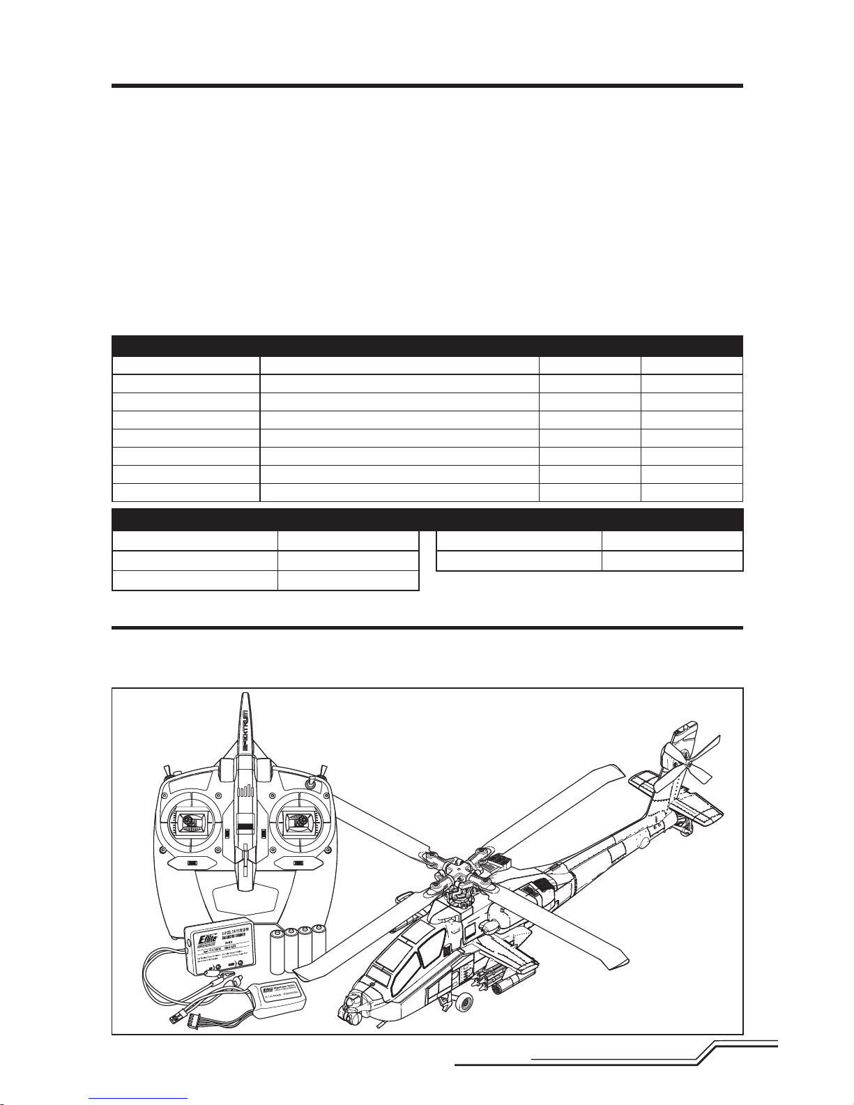
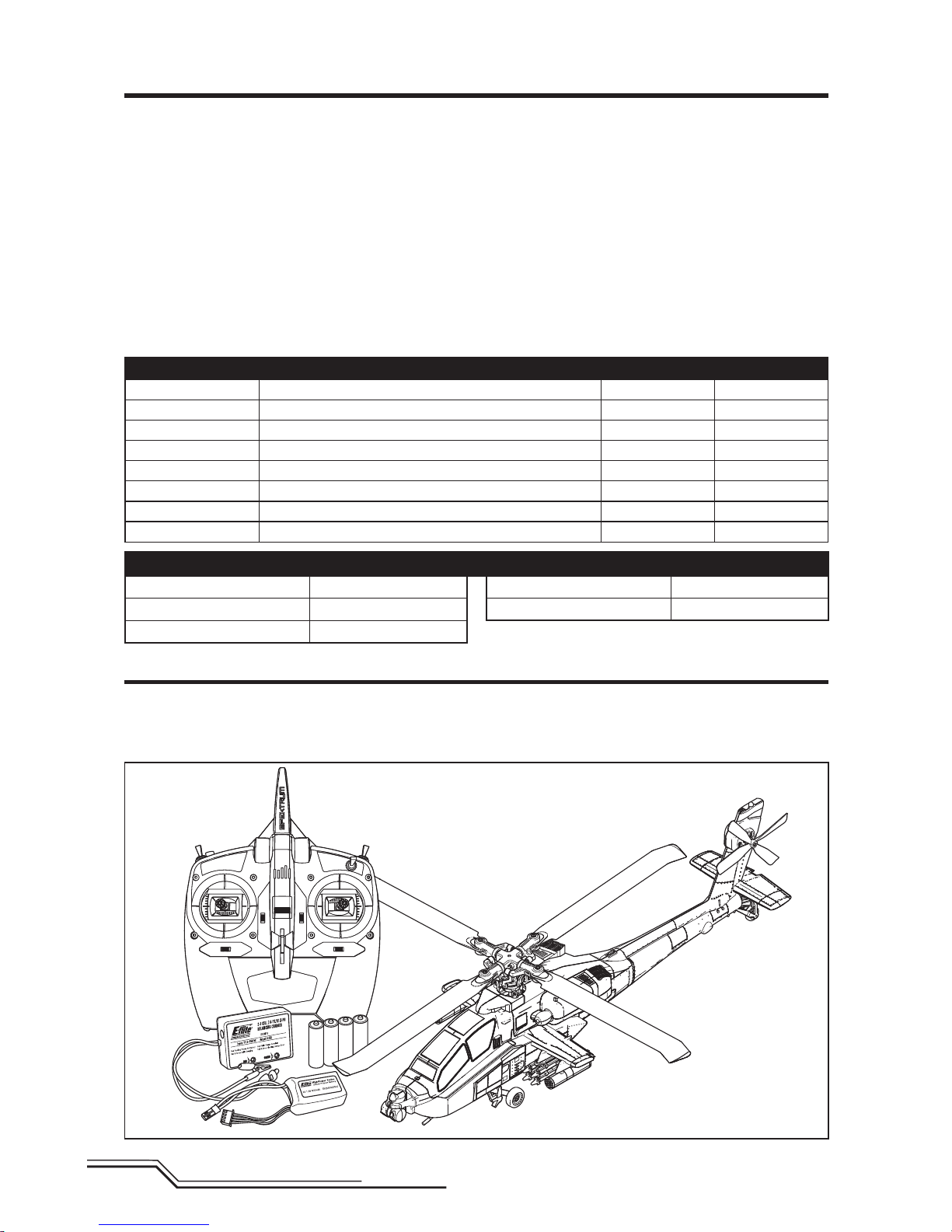
Box Contents
• Blade® AH-64 Apache
• Spektrum™ DXe Transmitter (RTF Only)
• 400mAh 2S 7.4V 30 C Li-Po Battery
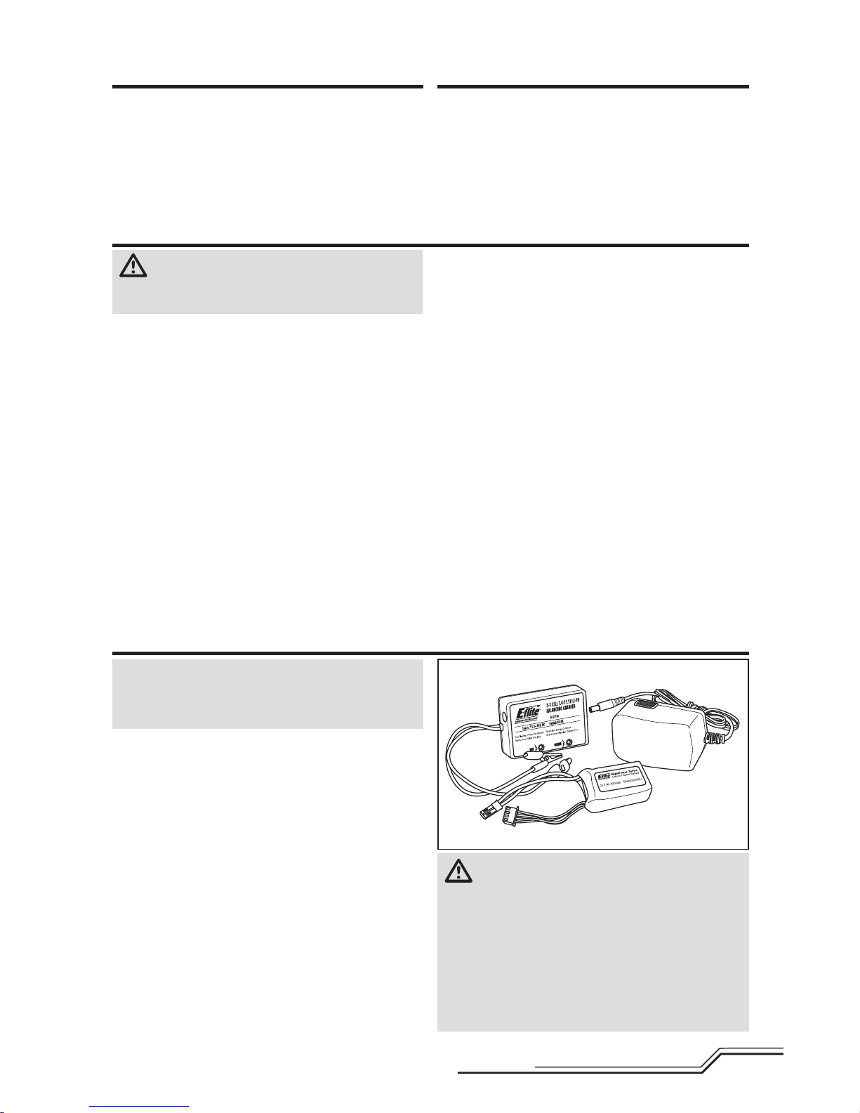
• E-fl ite® 2-3 Cell LiPo Balancing Charger, 0.65A with AC
to 12VDC Power Supply
• 4 AA Batteries (RTF Only)
Table of Contents
Length
14.76 in (375mm)
Height
3.74 in (95mm)
Main Rotor Diameter
12.51 in (318mm)
Tail Rotor Diameter
2.56 in (65mm)
Flying Weight
6.70 oz (190 g)
Specifications
Components RTF BNF
Airframe
Blade® AH-64 Apache
Included Included
Main Motor
6000kv Brushless Outrunner
Installed Installed
Tail Motor
4800k Brushless Outrunner
Installed Installed
Receiver
Spektrum AR6335
Installed Installed
ESC
Dual Brushless
Installed Installed
Battery
400mAh 2S 7.4V 30 C Li-Po Battery
Included Included
Charger
2-3 Cell LiPo Balancing Charger, 0.65A
Included Included
Transmitter
DSM2®/DSMX® Compatible Transmitter
DXe Included Required
To register your product online,visit www.bladehelis.com
Safety Precautions and Warnings ...................................... 2
Table of Contents .............................................................. 3
Box Contents .................................................................... 3
First Flight Preparation ...................................................... 4
Flying Checklist ................................................................4
Charging Warnings............................................................ 4
Battery Charging ............................................................... 4
Installing the DXe Transmitter Batteries (RTF) .................... 5
DXe Transmitter Control (RTF) ...........................................5
Transmitter Setup Table (BNF) ........................................... 6
Installing the Flight Battery ...............................................8
Transmitter and Receiver Binding ...................................... 8
SAFE
®
Technology ............................................................ 9
Flight Mode and Rate Selection ......................................... 9
Panic Recovery .................................................................9
Throttle Hold ................................................................... 10
Control Tests ................................................................... 10
Understanding the Primary Flight Controls ......................11
Flying the AH-64 Apache ................................................. 12
Advanced Settings ..........................................................12
Servo Adjustment ........................................................... 14
Trim Flight ......................................................................15
Post-Flight Inspection and Maintenance Checklist ........... 16
Troubleshooting Guide ....................................................16
Exploded View ................................................................ 18
Parts Listings .................................................................. 18
Optional Parts .................................................................18
Limited Warranty ............................................................ 19
Warranty and Service Contact Information ......................20
FCC Information .............................................................. 20
IC Information .................................................................20
Compliance Information for the European Union .............. 21
Page 4
4
EN
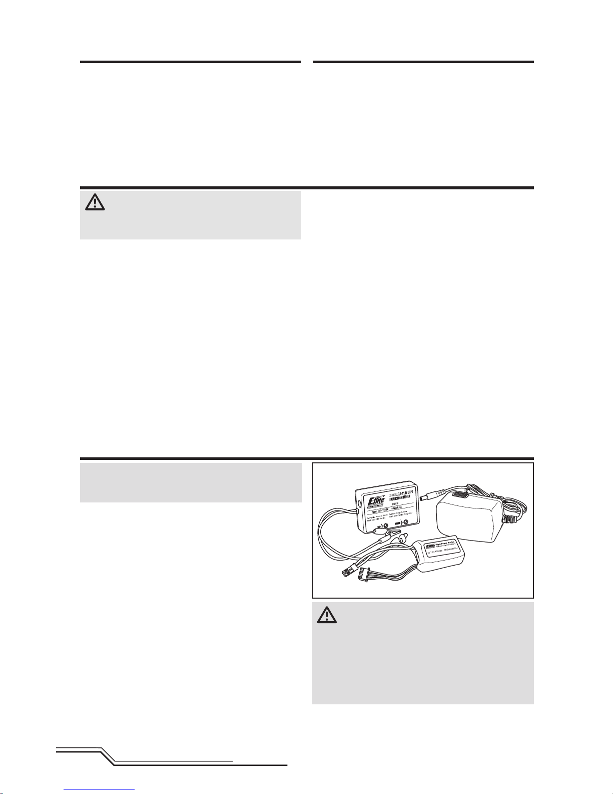
NOTICE: Charge only batteries that are cool to the touch
and are not damaged. Look at the battery to make sure it
is not damaged e.g., swollen, bent, broken or punctured.
1. Connect the AC to DC adapter to an AC outlet.
2. Connect the AC to DC adapter to the charger.
3. Connect the battery balance lead to the charger.
The connector is keyed to prevent reverse
polarity connection.
4. Always disconnect the fl ight battery from the charger
immediately upon completion of charging.
LED Indicators
Red Flashing LED: Input power with no battery connected
R ed and Green Solid LEDs: Battery connected and
charging
Red Solid LED: Charge complete
Red and Green Flashing LEDs: Charge error
Charging a fully discharged (not over-discharged) 400mAh
battery takes approximately 30-45 minutes.
The charger can also be powered through the DC alligator
clips. Connect them to a 11.5–15V DC power source, noting proper polarity.
CAUTION: Do not connect to AC and DC power
sources at the same time. Doing so may cause
a short circuit, resulting in damage to the product,
personal injury or property damage.
NOTICE: Always connect cable polarities correctly.
Consult the battery instructions, safety sheet or product
support before using a 12V battery with sources other
than a standard AC wall outlet.
Battery Charging
First Flight Preparation
• Remove and inspect contents
• Begin charging the fl ight battery
• Program your computer transmitter (BNF only)
• Install the fl ight battery in the helicopter
(once it has been fully charged)
• Bind your transmitter (BNF only)
• Familiarize yourself with the controls
• Find a suitable area for fl ying
Flying Checklist
❏ Always turn the transmitter on fi rst
❏ Plug the fl ight battery into the lead from the ESC
❏ Allow the receiver and ESC to initialize and arm properly
❏ Fly the model
❏ Land the model
❏ Unplug the fl ight battery from the ESC
❏ Always turn the transmitter off last
CAUTION: All instructions and warnings
must be followed exactly. Mishandling of Li-Po
batteries can result in a fi re, personal injury and/or
property damage.
• NEVER LEAVE CHARGING BATTERIES UNATTENDED.
• NEVER CHARGE BATTERIES OVERNIGHT.
• By handling, charging or using the included Li-Po
battery, you assume all risks associated with lithium
batteries.
• If at any time the battery begins to balloon or swell,
discontinue use immediately. If charging or discharging,
discontinue and disconnect. Continuing to use, charge
or discharge a battery that is ballooning or swelling can
result in fi re.
• Always store the battery at room temperature in a dry
area for best results.
• Always transport or temporarily store the battery in a
temperature range of 40–120º F (5–49° C).
• Do not store battery or model in a car or direct sunlight.
If stored in a hot car, the battery can be damaged or
even catch fi re.
• Always charge batteries away from fl ammable
materials.
• Always inspect the battery before charging
• Always disconnect the battery after charging, and
let the charger cool between charges.
• Always constantly monitor the temperature of the
battery pack while charging.
• ONLY USE A CHARGER SPECIFICALLY DESIGNED TO
CHARGE LI-PO BATTERIES. Failure to charge the battery
with a compatible charger may cause a fi re resulting in
personal injury and/or property damage.
• Never discharge Li-Po cells to below 3V under load.
• Never cover warning labels with hook and loop strips.
• Never charge batteries outside recommended levels.
• Never charge damaged batteries.
• Never attempt to dismantle or alter the charger.
• Never allow minors to charge battery packs.
• Never charge batteries in extremely hot or cold places
(recommended between 40–120° F or
(5–49° C) or place in direct sunlight.
Charging Warnings
Page 5
5
EN
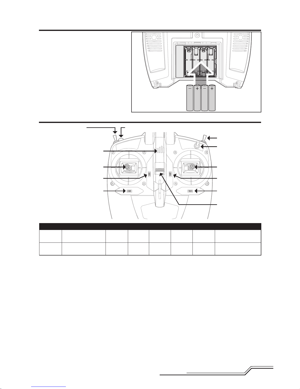
Fli ght Mode Switch
0 = Stability Mode (NORM)
1 = Intermediate Mode (FM1)
2 = Agility Mode (FM2)
Bind/Panic Switch
Throttle Hold
Du al Rate Switch
Installing the DXe Transmitter Batteries (RTF)
DXe Transmitter Control (RTF)
The LED indicator fl ashes and the transmitter
beeps progressively faster as the battery voltage
drops.
Replace the transmitter batteries when the
transmitter begins to beep.
A
B
C
D
E
F
G
LED Indicator
ABCDEF G
Mode 1
Aileron (Left/Right)
Throttle (Up/Down)
Throttle
Trim
Aileron
Trim
ON/OFF
Switch
Rudder
Trim
Elevator
Trim
Rudder (Left/Right)
Elevator (Up/Down)
Mode 2
Aileron (Left/Right)
Elevator (Up/Down)
Elevator
Trim
Aileron
Trim
ON/OFF
Switch
Rudder
Trim
Throttle
Trim
Rudder (Left/Right)
Throttle (Up/Down)
Page 6
6
EN
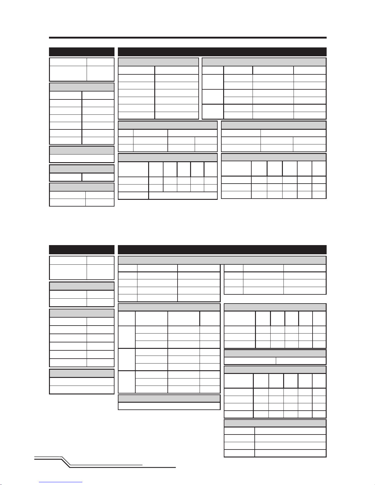
Transmitter Setup Table (BNF)
D/R & Expo
Chan
Switch Pos
(Ail D/R) D/R Expo
AILE
0 100/100 +25
1 100/100 +25
2 75/75 +25
ELEV
0 100/100 +25
1 100/100 +25
2 75/75 +25
RUDD
0 100/100 +25
1 100/100 +25
2 75/75 +25
D/R & Expo
Chan Sw Pos D/R Expo
AILE
0 100 +25
1 75 +25
ELEV
0 100 +25
1 75 +25
RUDD
0 100 +25
1 75 +25
Mix 1
GYRO->GYRO ACT
Rate D+125% U+125%
SW ELE D/R TRIM – INH
Timer
Mode Count Down
Time 5:00 Tone
Start Throttle Out
Over 25%
Timer
Down Timer 5:00
Switch THR CUT
SYSTEM SETUP
Model Type HELI
Swash Type 1 servo
Normal
F-Mode Setup
Flight Mode F Mode
Hold Hold
SW Select
Trainer Aux 2
F Mode Gear
Gyro INH
Mix INH
Hold INH
Knob INH
Frame Rate
11ms
DSMX
Chan Travel Reverse
THR 100/100 Normal
AIL 100/100 Normal
ELE 100/100 Normal
RUD 100/100 Normal
Chan Travel Reverse
GER 100/100 Normal
PIT 100/100 Normal
AX2 100/100 Normal
Servo Setup
FUNCTION LIST
ADJUST LISTSETUP LIST
DX6i
DX7s, DX8
Throttle Curve
Switch Pos
(F Mode)
Pos 1Pos 2Pos 3Pos 4Pos
5
NORM 0 25 50 75 100
STUNT 100 90 85 90 100
HOLD 0
Throttle Curve
Switch Pos
(F Mode) Pt 1 Pt 2 Pt 3 Pt 4 Pt 5
N 0 25 50 75 100
1 100 80 75 80 100
2 100 90 85 90 100
TRAVEL ADJ
Channel Travel
THRO 100/100
AILE 100/100
ELEV 100/100
RUDD 100/100
GYRO 100/100
PITC 100/100
REVERSE
Channel Direction
THRO N
AILE N
ELEV N
RUDD N
GYRO N
PITC R
GYRO
RATE SW-F.MODE
0 88% NORM 0
1 12% STUNT 1
Modulation Type
AUTO DSMX-ENABLE
D/R COMBI
D/R SW AILE
Model Type HELI
Swash Type
1 servo
Normal
Pitch Curve
Switch Pos
(F Mode)
Pos 1Pos 2Pos 3Pos 4Pos
5
NORM 30 40 50 75 100
STUNT 0 25 50 75 100
HOLD 25 37 50 75 100
Pitch Curve
Switch Pos
(F Mode) Pt 1 Pt 2 Pt 3 Pt 4 Pt 5
N 30 40 50 75 100
1 0 25 50 75 100
2 0 25 50 75 100
HOLD 25 37 50 75 100
Panic Mode Operation
ELEV D/R Switch
Sw Pos 0 = Panic Mode Off
Sw Pos 1 = Panic Mode On
Once the model has returned to level you must manually return the Panic Mode
Switch to the off position otherwise the cyclic and tail rotor controls will be reduced.
Panic Mode Operation
Trainer/Bind Button
Pressed = Panic Mode On
Released = Panic Mode Off
Throttle Cut
Throttle 0%
Gyro
INH
Page 7
7
EN
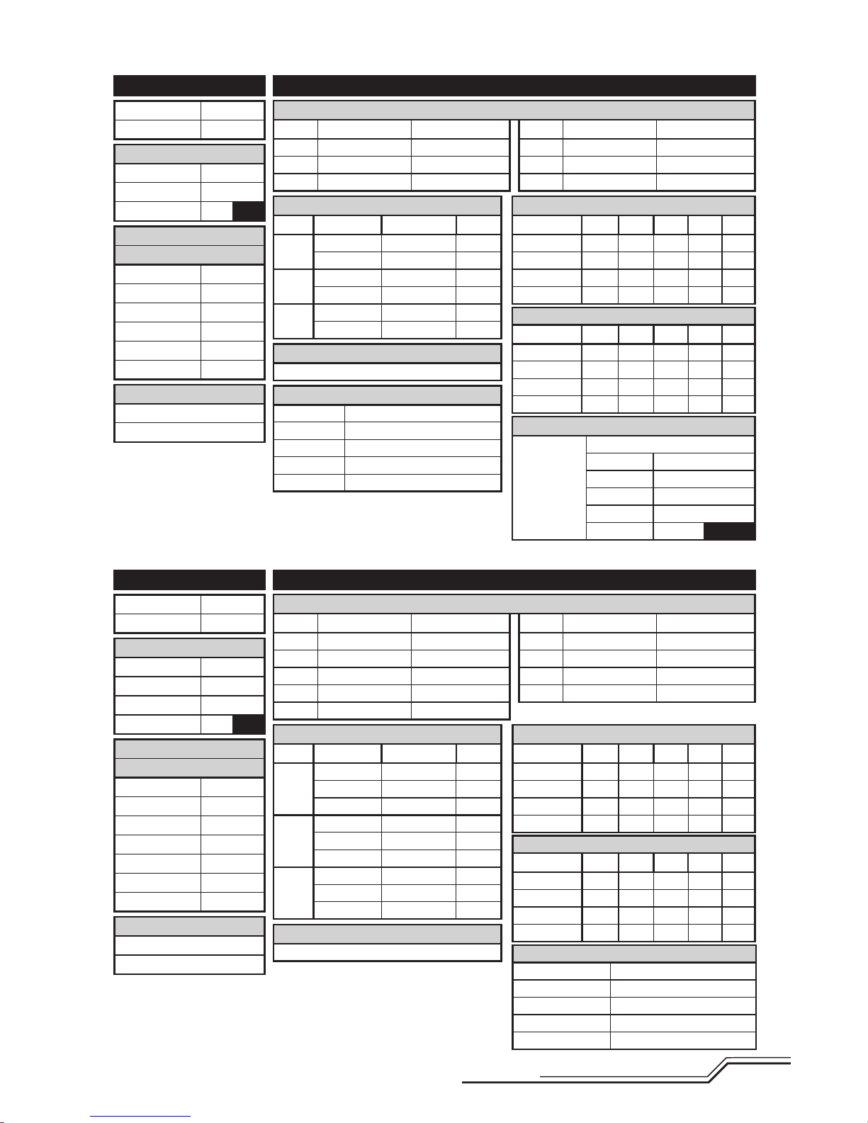
D/R & Expo
Chan Sw (F) Pos D/R Expo
AILE
0 100/100 +25
1 75/75 +25
ELEV
0 100/100 +25
1 75/75 +25
RUDD
0 100/100 +25
1 75/75 +25
Gyro
Inhibit
D/R & Expo
Chan Sw (F) Pos D/R Expo
AILE
0 100/100 +25
1 100/100 +25
2 75/75 +25
ELEV
0 100/100 +25
1 100/100 +25
2 75/75 +25
RUDD
0 100/100 +25
1 100/100 +25
2 75/75 +25
Gyro
Inhibit
Mixing
P-Mix 1
Normal
Channels -I- > Ger
Rate 0/–125
Offset 100
Switch Switch I
Position 0
1
Timer
Mode Count Down
Time 5:00
Start Throttle Out
Over 25%
One Time Inhibit
SYSTEM SETUP
Model Type HELI
Swash Type Normal
F-Mode Setup
Switch 1 Switch B
Hold Switch Switch H
0
1
Channel Assign
Channel Input
1 Throttle
2 Aileron
3 Elevator
4 Rudder
5 Gear Switch B
6 Collective
Frame Rate
11ms
DSMX
SYSTEM SETUP
Model Type HELI
Swash Type Normal
F-Mode Setup
Switch 1 Switch B
Switch 2 Inhibit
Hold Switch Switch H
0
1
Channel Assign
Channel Input
1 Throttle
2 Aileron
3 Elevator
4 Rudder
5 Gear Switch B
6 Collective
7 AUX 2 Switch I
Frame Rate
11ms
DSMX
Chan Travel Reverse
THR 100/100 Normal
AIL 100/100 Normal
ELE 100/100 Normal
Chan Travel Reverse
RUD 100/100 Normal
GER 100/100 Normal
PIT 100/100 Normal
Chan Travel Reverse
THR 100/100 Normal
AIL 100/100 Normal
ELE 100/100 Normal
RUD 100/100 Normal
GER 100/100 Normal
Chan Travel Reverse
PIT 100/100 Normal
AX2 100/100 Normal
AX3 100/100 Normal
AX4 100/100 Normal
Servo Setup
Servo Setup
FUNCTION LIST
FUNCTION LIST
DX6
DX7 (new), DX9, DX18
Panic Mode Operation
Bind / I Button
Pressed = Panic Mode On
Released = Panic Mode Off
Panic Mode Operation
Bind / I Button
Pressed = Panic Mode On
Released = Panic Mode Off
Timer
Mode Count Down
Time 5:00
Start Throttle Out
Over 25%
One Time Inhibit
Throttle Curve
Sw (B) Pos Pt 1 Pt 2 Pt 3 Pt 4 Pt 5
N 0 25 50 75 100
1 100 80 75 80 100
2 100 90 85 90 100
HOLD 0 0 0 0 0
Throttle Curve
Sw (B) Pos Pt 1 Pt 2 Pt 3 Pt 4 Pt 5
N 0 25 50 75 100
1 100 80 75 80 100
2 100 90 85 90 100
HOLD 0 0 0 0 0
Pitch Curve
Sw (B) Pos Pt 1 Pt 2 Pt 3 Pt 4 Pt 5
N 30 40 50 75 100
1 0 25 50 75 100
2 0 25 50 75 100
HOLD 25 37 50 75 100
Pitch Curve
Sw (B) Pos Pt 1 Pt 2 Pt 3 Pt 4 Pt 5
N 30 40 50 75 100
1 0 25 50 75 100
2 0 25 50 75 100
HOLD 25 37 50 75 100
Page 8
8
EN
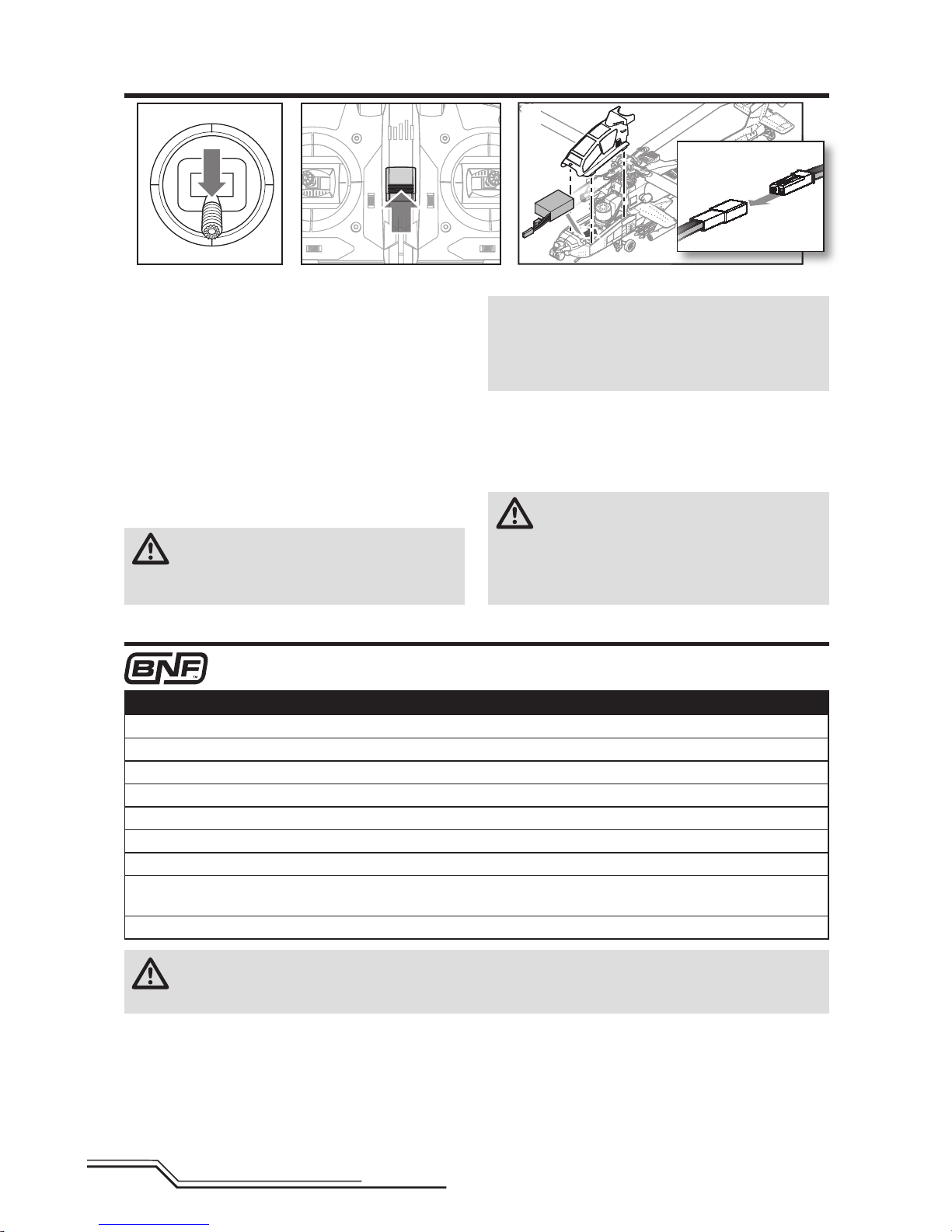
To bind or re-bind your helicopter to your chosen transmitter, please follow the directions below.
General Binding Procedure
1. Disconnect the fl ight battery from the helicopter.
2. Refer the Transmitter Setup Table to correctly setup your transmitter.
3. Lower the throttle stick to the lowest position. Set all trims to the center position.
4. Power off the transmitter and move all switches to the 0 position. Move the throttle to the low/off position.
5. Install the bind plug in the bind port extension located inside the hatch.
6. Connect the fl ight battery to the ESC.
7. Put the transmitter into bind mode while powering on the transmitter.
8. Release the bind button/switch after 2–3 seconds. The helicopter is bound when swashplate responds to control stick
movement.
9. Disconnect the fl ight battery and power the transmitter off.
CAUTION: When using a Futaba® transmitter with a Spektrum™ DSM2® module, you must reverse the
throttle channel and re-bind. Refer to your Spektrum module manual for binding and failsafe instructions.
Refer to your Futaba transmitter manual for instructions on reversing the throttle channel.
Transmitter and Receiver Binding
1. Lower the throttle stick to the lowest position.
2. Power ON the transmitter.
3. Center all trims. For the included Spektrum DXe
transmitter (RTF only), the trims are centered when
you hear a higher pitched beep while pressing the trim
button. Move the trim in both directions until you hear
the high-pitched beep.
4. Remove the canopy by lifting straight up.
5. Insert the battery as shown, moving the motor wires
to the side, pushing down and back until the battery
lays fl at.
6. Connect the battery connector to the ESC noting
correct polarity.
CAUTION: Connecting the battery to the ESC
with reversed polarity will cause damage to the
ESC, the battery or both. Damage caused by incorrectly
connecting the battery is not covered under warranty.
7. Replace the canopy.
NOTICE: Ensure the battery and ESC leads do not
contact the motor after installation. Failure to do so
could cause excessive wear to the motor or cause the
wires to short, causing a crash. Crash damage is not
covered under warranty.
8. Place the helicopter on a fl at surface and leave it still
until the ESC beeps twice, indicating initialization is
complete.
If you experience issues during initialization, refer to the
Troubleshooting Guide at the back of the manual.
CAUTION: Always disconnect the Li-Po
battery from the aircraft when not fl ying to
avoid over-discharging the battery. Batteries discharged
to a voltage lower than the lowest approved voltage
may become damaged, resulting in loss of performance
and potential fi re when batteries are charged.
Installing the Flight Battery
1 2
3
Page 9
9
EN
DXe Binding Procedure
1. Disconnect the fl ight battery from the helicopter.
2. Lower the throttle stick to the lowest position. Set all trims to the center position.
3. Power off the transmitter.
4. Install the bind plug in the bind port extension located inside the hatch.
5. Connect the fl ight battery to the ESC.
6. Press and hold the Bind Switch while powering on the transmitter.
7. The transmitter will beep and the LED will blink. Release the Bind Switch.
8. The helicopter is bound when the swashplate responds to control stick movement and the transmitter emits 3 rapid,
high-pitch tones. If the transmitter emits 2 low-pitch tones, the binding procedure was not successful and should be
attempted again.
9. Disconnect the fl ight battery and power the transmitter off.
If you encounter problems, obey binding instructions and refer to the troubleshooting guide for other instructions.
If needed, contact the appropriate Horizon Product Support offi ce. For a list of compatible DSM
®
transmitters, please
visit www.bindnfl y.com.
RTF
Your RTF transmitter comes prebound to the model. If you need to re-bind, follow the directions below.
Revolutionary SAFE
®
(Sensor Assisted Flight Envelope)
technology uses an innovative combination of multi-axis
sensors and software that allows model aircraft to know
its position relative to the horizon. This spatial awareness
is utilized to create a controlled fl ight envelope the aircraft
can use to maintain a safe region of bank and pitch angles
so you can fl y more safely. Far beyond stability, this level of
protection offers multiple modes so the pilot can choose to
develop his or her skills with a greater degree of security
and fl ight control that always feels crisp and responsive.
SAFE technology delivers:
• Flight envelope protection you can enable at the fl ip of
a switch.
• Multiple modes let you adapt SAFE technology to your
skill level instantly.
Best of all, sophisticated SAFE technology doesn’t require
any work to enjoy. Every aircraft with SAFE installed is
ready to use and optimized to offer the best possible fl ight
experience.
FlySAFERC.com
Technology
®
Flight Mode and Rate Selection
In Stability Mode the bank angle is limited. When the
cyclic stick is released the model will return to level.
In Intermediate Mode the bank angle is not limited. When
the cyclic stick is released the model will not return to
level. This mode is great for learning forward fl ight and
smooth scale maneuvers.
In Agility Mode the bank angle is not limited. When the
cyclic sticks is released the model will not return to level.
This mode is great for fast forward fl ight, inverted fl ight,
and mild aerobatics. The AH-64 Apache is designed for
scale fl ying, where the emphasis is placed upon smooth
and precise movements rather than 3D aerobatics. Change
rates by moving the two-position dual rate switch.
• Low rate reduces the control rates, providing an easier
to fl y model. Beginners should use low rate for initial
fl ights.
• High rate provides full control and should be used by
intermediate and experience pilots.
Panic Recovery
If you get into distress while fl ying in any mode, push and
hold the Bind/Panic Switch and move the control sticks to
their neutral position. SAFE technology will immediately
return the aircraft to an upright level attitude, if the aircraft
is at a suffi cient height with no obstacles in its path.
Return the collective stick to 50% and release the Panic
Switch to turn off Panic Recovery and return to the current
fl ight mode.
NOTICE: Before releasing the panic switch, make
sure the collective stick has been returned to the 50%
position. Once the panic switch has been released, full
negative collective becomes available, which could
cause the helicopter to descend rapidly.
• This mode is intended to provide the pilot with the
confi dence to continue to improve their fl ight skills.
• Move the collective stick to 50% and return all other
transmitter controls to neutral for the quickest recovery.
• Once the model has reached a level upright attitude the
negative collective is reduced preventing the user from
pushing the model into the ground.
Page 10
10
EN
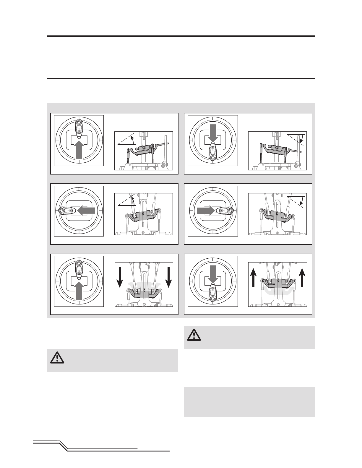
Elevator
Elevator down Elevator up
Left Side View Left Side View
Aileron
Collective Pitch
Aileron left
Collective pitch up Collective pitch down
Aileron right
Rear View
Rear View
Rear View
Rear View
Control Tests
Ensure the throttle hold is ON when doing the direction
control tests. Test the controls prior to the fi rst fl ight to
ensure the servos, linkages and parts operate correctly.
If the controls do not react as shown in the illustrations
below, confi rm the transmitter is programmed correctly
before continuing on to the Motor test.
Throttle Hold
Throttle hold is used to prevent the motor from powering
on inadvertently. For safety, turn throttle hold ON any time
you need to touch the helicopter or check the direction
controls.
Throttle hold is also used to turn off the motor quickly if the
helicopter is out of control, in danger of crashing, or both.
The blades will continue to spin briefl y when throttle hold is
activated. Pitch and direction control is still maintained.
Motor
Place the helicopter outdoors on a clean, fl at and level
surface (concrete or asphalt) free of obstructions. Always
stay clear of moving rotor blades.
CAUTION: Keep pets and other animals away
from the helicopter. Animals may injure themselves
if they attack or run toward the helicopter.
1. Both motors beep 3 times when the helicopter’s ESC
arms properly. Before you continue, confi rm that
throttle is at full low position.
2. Turn Throttle Hold OFF.
WARNING: Stay at least 30 feet (10 meters) away
from the helicopter when the motor is running. Do
not attempt to fl y the helicopter at this time.
3. Slowly increase the throttle until the blades begin to
spin. The main blades should spin counterclockwise
when viewing the helicopter from the top. The tail rotor
blades should spin clockwise when viewing the
helicopter from the left side.
NOTICE: If the main rotor blades are spinning clockwise,
reduce the throttle to low immediately. Disconnect the
battery from the helicopter and reverse any two motor wire
connections to the ESC and repeat the motor control test.
Page 11
11
EN
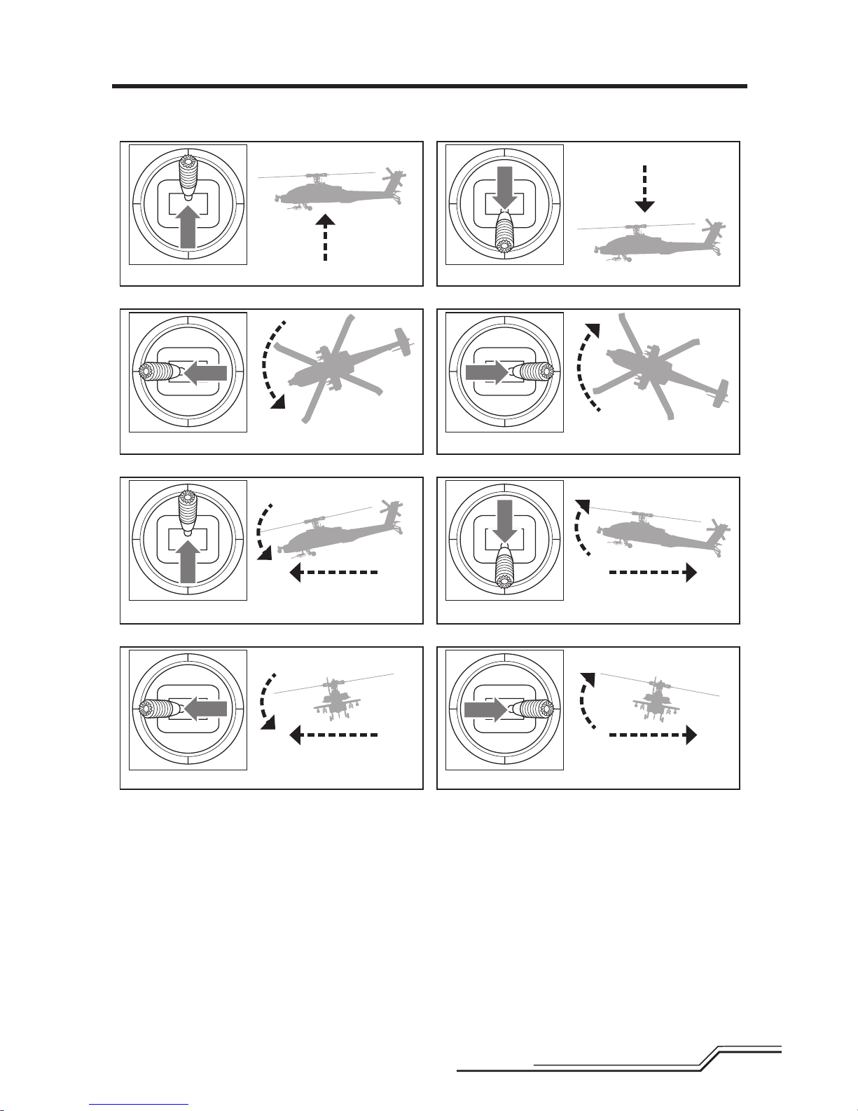
Understanding the Primary Flight Controls
If you are not familiar with the controls of your AH-64 Apache, take a few minutes to familiarize yourself with them before
attempting your fi rst fl ight.
Descend
Nose Yaws Left
Rudder left
Throttle up
Rudder right
Throttle down
Climb
Collective
Rudder
Left Side View Left Side View
Forward
Left
Backward
Right
Elevator forward
Aileron left
Elevator back
Aileron right
Elevator
Aileron
Left Side View
Rear ViewRear View
Nose Yaws Right
Left Side View
Page 12
12
EN
Flying the AH-64 Apache
Advanced Settings
Consult your local laws and ordinances before choosing a
location to fl y your aircraft.
We recommend fl ying your aircraft outside in calm winds
or inside a large gymnasium. Always avoid fl ying near
houses, trees, wires and buildings. You should also be
careful to avoid fl ying in areas where there are many
people, such as busy parks, schoolyards or soccer fi elds.
It is best to fl y from a smooth fl at surface as this will allow
the model to slide without tipping over. Keep the helicopter
approximately 2 ft (600mm) above the ground. Keep the
tail pointed toward you during initial fl ights to keep the
control orientation consistent. Releasing the stick in Stability Mode will allow the helicopter to level itself. Activating
the Panic Recovery button will level the helicopter quickly.
If you become disoriented while in Stability Mode, slowly
lower the throttle stick to land softly.
During initial fl ights, only attempt takeoff, landing and
hovering in one spot.
Takeo
NOTICE: If the main motor or tail motor do not startup
properly when throttle is fi rst applied, immediately return
the throttle to idle and try again. If the problem persists,
disconnect the fl ight battery, check for binding in the
gear train and ensure no wires have become entangled
within the gears.
Place the model onto a fl at, level surface free of obstacles
and walk back 30 feet (10 meters). Slowly increase the
throttle until the model is approximately 2 ft. (600mm)
off the ground and check the trim so the model fl ies as
desired. Once the trim is adjusted, begin fl ying the model.
Hovering
Making small corrections on the transmitter, try to hold
the helicopter in one spot. If fl ying in calm winds, the
model should require almost no corrective inputs. After
moving the cyclic stick and returning it to center the
model should level itself. The model may continue to
move due to inertia. Move the cycle stick in the opposite
direction to stop the movement.
After you become comfortable hovering, you can progress
into fl ying the model to different locations, keeping the tail
pointed towards you at all times. You can also ascend and
descend using the throttle stick. Once you’re comfortable
with these maneuvers, you can attempt fl ying with the tail
in different orientations. It is important to keep in mind
that the fl ight control inputs will rotate with the helicopter,
so always try to picture the control inputs relative to the
nose of the helicopter. For example, forward will always
drop the nose of the helicopter.
Low Voltage Cuto (LVC)
LVC decreases the power to the motors when the battery
voltage gets low. When the motor power decreases and the
white LED on the top of the fuselage fl ashes quickly, land
the aircraft immediately and recharge the fl ight battery.
LVC does not prevent the battery from over-discharge
during storage.
NOTICE: Repeated fl ying to LVC will damage the battery.
Landing
To land, slowly decrease the throttle while in a low-level
hover. After landing, disconnect and remove the battery
from the aircraft after use to prevent trickle discharge. Fully
charge your battery before storing it. During storage, make
sure the battery charge does not fall below 3V per cell.
The AH-64 Apache default settings are appropriate for most
users. We recommend fl ying with the default parameters
before making any adjustments.
WARNING: To ensure your safety, always
disconnect the motor wires from the ESC
before performing the following steps. After you have
completed the adjustments, reconnect the motor wires
to the ESC before attempting to fl y the model.
Gain Parameters
1. Cyclic P Gain Adjustment (Default 100%)
Higher gain will result in greater stability. Setting the gain
too high may result in random twitches if your model
has an excessive level of vibration. High frequency
oscillations may also occur if the gain is set too high.
Lower gain will result in less stability. Too low of a value
may result in a less stable model particularly outdoors
in winds.
If you are located at a higher altitude or in a warmer
climate, higher gains may be benefi cial—the opposite
is true for lower altitude or colder climates.
2. Cyclic I Gain Adjustment (Default 100%)
Higher gain will result in the model remaining still, but
may cause low frequency oscillations if increased too far.
Lower gain will result in the model drifting slowly.
If you are located at a higher altitude or in a warmer
climate, higher gains may be benefi cial—the opposite
is true for lower altitude or colder climates.
3. Cyclic D Gain Adjustment (Default 100%)
Higher gain will improve the response rate of your inputs.
If the gain is raised too much, high frequency oscillations
may occur.
Lower gain will slow down the response to inputs.
Page 13
13
EN
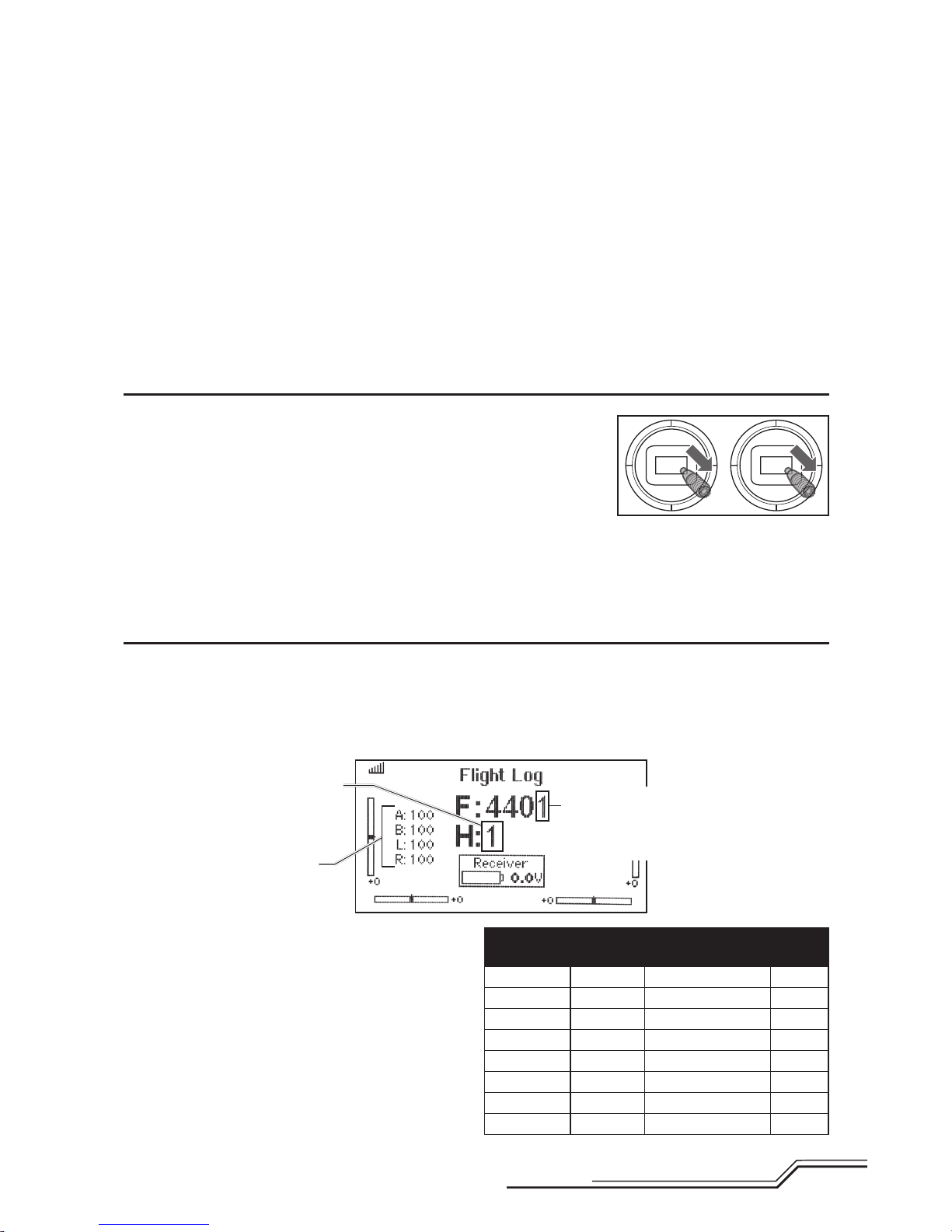
Once you have entered Gain Adjustment Mode, move the
cyclic stick right and left to select the gain parameter to
adjust. Moving the stick right will select the next parameter.
Moving the stick left will select the previous parameter.
The selected gain parameter is indicated on the Flight Log
screen above and by the lean of the swashplate on the roll
axis as shown in the table at the right.
Parameter #
Display
location
Swash Position Page #
1 A 100% to the Left 1
2 B 70% to the Left 1
3 L 40% to the Left 1
4 R 10% to the Left 1
5 A 10% to the Right 2
6 B 40% to the Right 2
7 L 70% to the Right 2
8 R 100% to the Right 2
4. Cyclic Response (Default 100%)
Higher cyclic response will result in a more aggressive
cyclic response.
Lower cyclic response will result in a less aggressive
cyclic response.
5. Tailrotor P Gain Adjustment (Default 100%)
Higher gain will result in greater stability. Setting
the gain too high may result in random twitches if
your model has an excessive level of vibration. High
frequency oscillations may also occur if the gain is set
too high.
Lower gain may result in a decrease in stability. Too low
of a value may result in a less stable model particularly
outdoors in winds.
If you are located at a higher altitude or in a warmer
climate, higher gains may be benefi cial—the opposite
is true for lower altitude or colder climates.
6. Tailrotor I Gain Adjustment (Default 100%)
Higher gain results in the tail remaining still. If the gain is
raised too far, low speed oscillations may occur.
Lower gain will result in the tail drifting in fl ight over time.
If you are located at a higher altitude or in a warmer
climate, higher gains may be benefi cial—the opposite is
true for lower altitude or colder climates.
7. Tailrotor D Gain Adjustment (Default 100%)
Higher gain will improve the response rate to your inputs.
If raised too far, high frequency oscillations may occur.
Lower gain will slow down the response to inputs, but will
not have an effect on stability.
8. Tailrotor Adaptive Filtering
Higher gain will reduce oscillations during high speed
fl ight and when using large amounts of collective.
Lower gain will improve tail performance but may lead
to tail oscillations.
Entering Gain Adjustment Mode
1. Lower the throttle stick to the lowest position.
2. Power ON the transmitter.
3. Install the fl ight battery on the helicopter frame,
securing it with the hook and loop strap.
4. Connect the battery connector to the ESC.
5. Place the helicopter on a fl at surface and leave it still
until the orange receiver LED glows solid, indicating
initialization is complete.
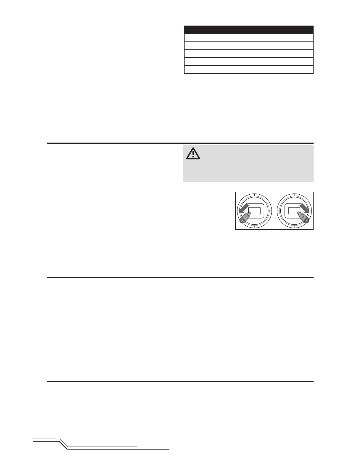
6. Move and hold
both transmitter
sticks to the bottom right corner
as shown.
7. Press and hold the bind/panic switch until the swash
servos move.
8. Release the sticks and the bind/panic switch. The
model is now in Gain Adjustment Mode.
9. Proceed to Adjusting the Gain Values to make any
desired changes.
Adjusting the Gain Values
If you are using a Spektrum™ telemetry-enabled transmitter, the gain adjustments can be viewed on the Flight Log
screen. Refer to your transmitter instructions to locate this
screen. The gain parameter currently selected will fl ash
on the transmitter screen. If you are not using a Spektrum
telemetry-enabled transmitter, the parameter and gain
values are indicated by the position of the swashplate on
the helicopter.
P age number
1 = Cyclic gains
2 = Tail rotor gains
Gain parameter
selected
Gain value
display location
Flight Log Screen
Page 14
14
EN
Servo Adjustment
The current gain value for the selected parameter is
indicated on the Flight Log screen and by the angle of the
swashplate (forward or backward) as shown in the table
at the right.
Move the cyclic stick forward or backward to adjust the
gain value. Moving the stick forward will increase the gain
value. Moving the stick backward will decrease the gain
value.
It is always best to adjust one gain at a time. Make small
adjustments (5% or less) and test fl y the model to evaluate
the adjustments that were made.
If you would like to reset the current gain value to the
default value of 100%, move and hold the rudder stick full
right for 1 second. The swash will level on the pitch axis,
indicating a 100% gain setting.
Saving the Gain Adjustments
1. Lower the throttle stick to the lowest position and
release the sticks.
2. Press and hold switch I until the swash servos move.
3. Release switch I to save the gain adjustments.
4. Reconnect the main drive motor to the ESC. Your model
is now ready for fl ight.
Swash Position Gain Value
Full backward 0%
50% backward 50%
Level forward and backward 100%
50% forward 150%
Full forward 200%
Your helicopter was setup at the factory and test fl own.
The servo adjustment steps are usually only necessary in
special circumstances, such as after a crash or if a servo
or linkage is replaced.
WARNING: To ensure your safety, always discon-
nect the motor wires from the ESC before performing the following steps. After you have completed the
adjustments, reconnect the motor wires to the ESC before
attempting to fl y the model.
Entering Servo Adjustment Mode
1. Lower the throttle stick to the lowest position.
2. Power ON the transmitter.
3. Install the fl ight battery on the helicopter frame, securing it with the hook and loop strap.
4. Connect the battery connector to the ESC.
5. Place the helicopter on a fl at surface and leave it still
until the orange receiver LED glows solid, indicating
initialization is complete.
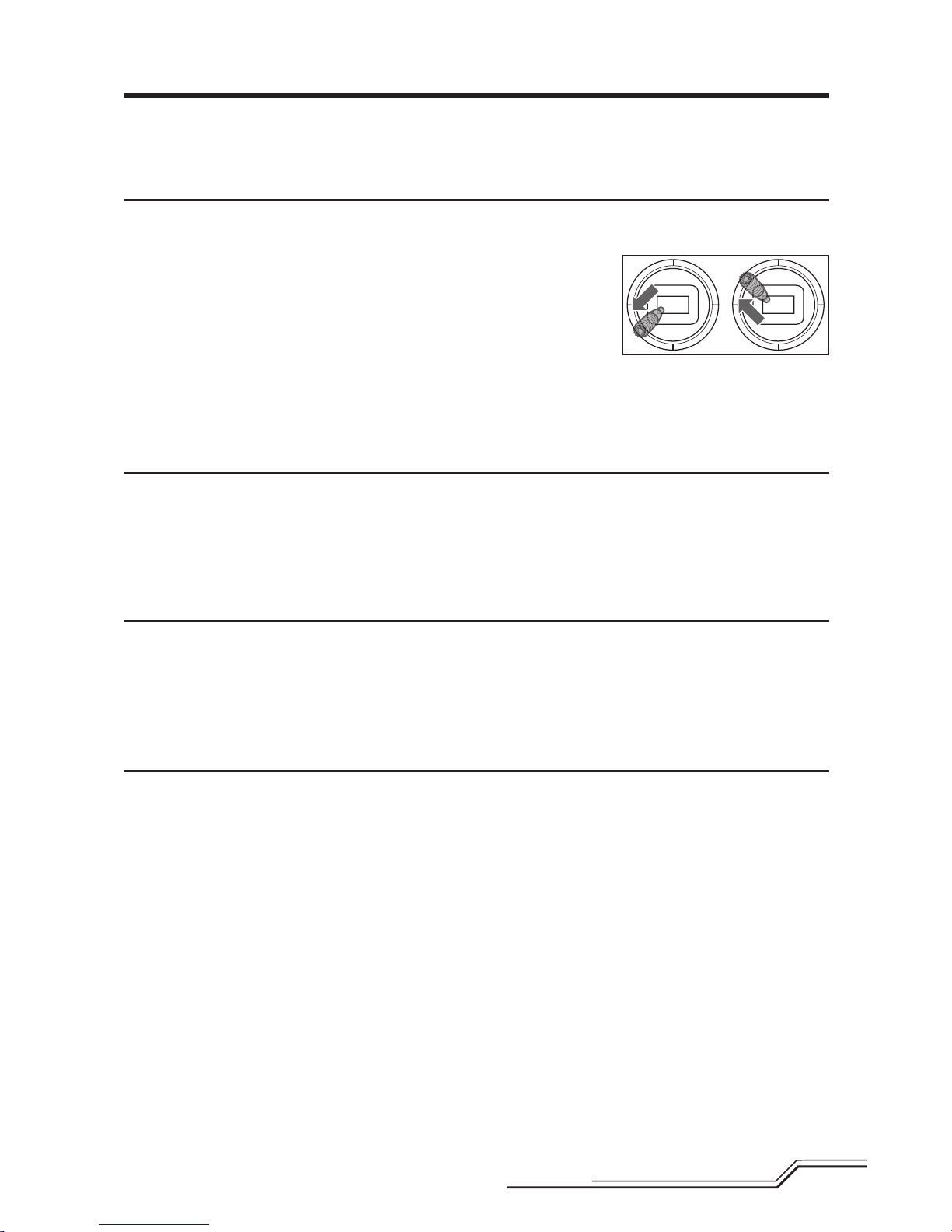
6. Hold the left stick
to the bottom
left corner and
the right stick to
the bottom right
corner as shown.
7. Hold the bind/panic switch until the swash servos
move.
8. Release the sticks and the bind/panic switch. The
model is now in Servo Adjustment Mode.
9. Proceed to Adjusting the Servo Neutral Position to
make any desired changes.
Adjusting the Servo Neutral Position
With the model in Servo Adjustment Mode, the control stick
and gyro inputs are disabled and the servos are held in the
neutral position. Check the position of the servo arms to
see if they are perpendicular to the servos.
• If the arms are perpendicular to the servos, no adjustment is necessary.
Exit Servo Adjustment Mode.
• If one or more servo arm is not perpendicular to the
servos, continue the servo adjustment process.
While watching the swashplate servos, apply right cyclic
and release. One of the servos will jump, indicating which
servo is selected. Press right cyclic and release until the
servo that needs to be adjusted is selected.
Once the servo you wish to adjust is selected, move the
cyclic stick forward or backward to adjust the servo neutral
position in the desired direction.
If you would like to reset the current servo to the default
neutral position, hold the rudder stick full right for 1
second.
The range of adjustment is limited. If you are unable to
adjust the servo arm to be perpendicular to the servo, you
must reset the servo to the default neutral position, remove
the servo arm and place it back onto the servo as close to
perpendicular as possible. You may then adjust the servo
neutral position using the forward/backward cyclic stick.
Saving the Servo Adjustments
Before saving your adjustments and exiting servo adjustment mode, verify the swashplate is level and both main
rotor blades are at 0 degrees. If they are not, make linkage
adjustments as necessary.
1. Lower the throttle stick to the lowest position and
release the sticks.
2. Press and hold switch I until the swash servos move.
3. Release switch I to save the servo adjustments.
4. Reconnect the main drive motor to the ESC. Your model
is now ready for fl ight.
All of the settings are stored internally, so your adjustments
will be maintained each time you initialize the model.
Page 15
15
EN
Trim Flight
Perform this procedure if the model is not performing well
or has been recently rebuilt from a crash.
The trim fl ight procedure was performed during the factory
test fl ight and only needs to be performed if you notice the
model is not returning to level consistently or if the model
does not remain still during stationary pirouettes. The trim
fl ight is used to determine the optimal SAFE® settings
during fl ight. The trim fl ight must be performed in calm
conditions.
Entering Trim Flight Mode
1. Lower the throttle stick to the lowest position.
2. Center all trims. For the included Spektrum DXe
transmitter (RTF only), the trims are centered when
you hear a higher pitched beep while pressing the
trim button. Move the trim in both directions until you
hear the high-pitched beep.
3. Power ON the transmitter.
4. Install the fl ight battery in the helicopter.
5. Connect the battery connector to the ESC.
6. Place the helicopter on a fl at surface and leave it still
until the motor beeps twice and the blue ESC LED
glows solid, indicating initialization is complete.
7. Place the helicopter where you are going to take off.
8. Move and hold
the left stick to
the bottom left
corner and the
right stick to the
top left corner
as shown.
9. Press and hold the bind/panic switch until the
swashplate rotates around once.
10. Release the sticks and bind/panic switch.
11. The model is ready for the trim fl ight.
Performing the Trim Flight
1. Slowly increase the throttle to lift the model into a
stationary hover. Make corrections as necessary to
keep the model still. Evaluation does not begin until the
throttle stick is over 50% and the sticks are centered.
Making corrections will not affect the result but a
longer fl ight may be necessary.
2. Keep the model stationary in a hover for a total of
30 seconds. Sliding and slow movements are okay.
The main goal is to keep the rotor disk level.
3. Once you are satisfi ed with the trim fl ight, land the
model.
Exiting Trim Flight Mode
1. After landing, lower the throttle stick to the lowest
position.
2. Press and hold the bind/panic switch for 2 seconds,
or until the swashplate twitches, indicating the servo
positions and attitude values have been recorded and
trim fl ight mode has been exited.
Flight Test
After performing the trim fl ight, test-fl y the model to
evaluate the leveling characteristics.
• The model should return to level fl ight consistently.
• During takeoff, the model should lift off with
minimal corrections.
• During a hover, the control stick should remain close to
center. Small corrections are acceptable.
If the model performs poorly or does not level properly
after the trim fl ight, retry the entire trim fl ight procedure.
If the problem persists, inspect the model for damaged
components, a bent shaft or anything that may result in
increased vibration. The trim fl ight may not record the correct values due to excessive vibration, fl ying in wind or the
model not staying level. In these cases, shorter trim fl ights
may be necessary. Try the 30-second, level trim fl ight
without corrections mentioned above fi rst. If the leveling
characteristics are not satisfactory, gradually shorten the
trim fl ights, checking for improvements until the model
performs as described at left.
Page 16
16
EN
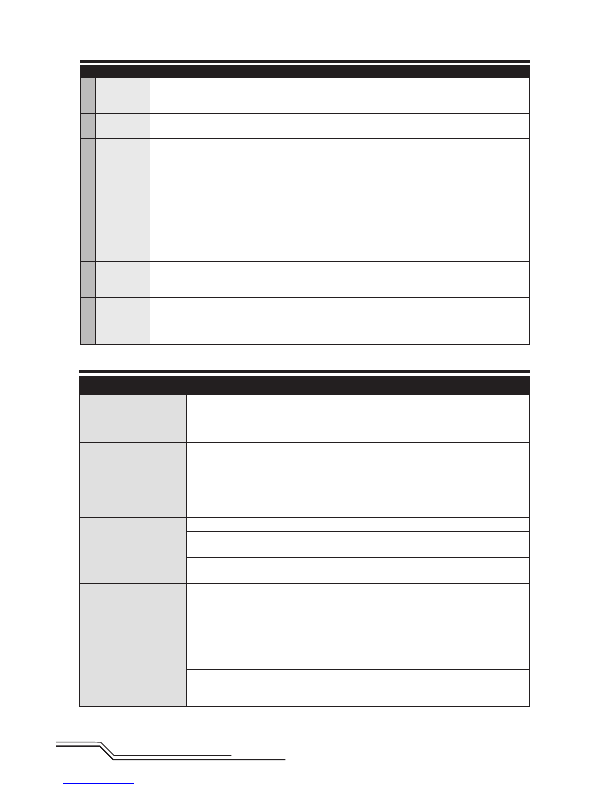
Troubleshooting Guide
Post-Flight Inspection and Maintenance Checklist
√
Ball Links
Make sure the plastic ball link holds the control ball, but is not tight (binding) on the ball. When a link
is too loose on the ball, it can separate from the ball during fl ight and cause a crash. Replace worn
ball links before they fail.
Cleaning
Make sure the battery is not connected before cleaning. Remove dust and debris with a soft brush or
a dry, lint-free cloth.
Bearings Replace bearings when they become notchy (sticky in places when turning) or draggy.
Wiring Make sure the wiring does not contact moving parts. Replace damaged wiring and loose connectors.
Fasteners
Make sure there are no loose screws, other fasteners or connectors. Do not over-tighten metal
screws in plastic parts. Tighten screws so the parts are mated together, then turn the screw only
1/8th of a turn more.
Rotors
Make sure there is no damage to rotor blades and other parts which move at high speed. Damage
to these parts includes cracks, burrs, chips or scratches. Replace damaged parts before fl ying. Verify
both main rotor blades have the correct and equal tension in the blade grips. When the helicopter is
held up sideways, the main blades should support their own weight. When the helicopter is shaken
lightly, the blades should fall.
Tail
Inspect the tail rotor for damage and replace if necessary. Verify the tail motor bolts, tail rotor adapter
bolts and tail motor mount bolts are properly tightened. Inspect the tail boom for any damage and
replace if necessary.
Mechanics
Inspect the main frame and landing gear for damage and replace if necessary. Check the mainshaft
for vertical play and adjust the locking collar if necessary. Verify that the main gear mesh is correct
and that no tight spots exist in the 360 degree rotation. Inspect all wires for damage and replace as
necessary.
Problem Possible Cause Solution
Helicopter control response
is inconsistent or requires
extra trim to neutralize
movement
Aircraft was not initialized properly or a vibration is interfering
with the sensor operation
Disconnect the fl ight battery, center the control trim
and re-initialize the helicopter
Helicopter will not respond
to throttle
Throttle too high and/or throttle
trim is too high
Disconnect the fl ight battery, place the throttle stick in
the lowest position and lower the throttle trim a few
clicks. Connect the fl ight battery and allow the model
to initialize
Helicopter moved during initialization
Disconnect the flight battery and re-initialize the helicopter while keeping the helicopter from moving
Helicopter has reduced
fl ight time or is underpowered
Flight battery charge is low Completely recharge the fl ight battery
Flight battery is damaged
Replace the fl ight battery and follow the fl ight battery
instructions
Flight conditions might be too cold
Make sure the battery is warm (room temperature)
before use
LED on receiver fl ashes
rapidly and aircraft will
not respond to transmitter
(during binding).
The receiver LED may be
diffi cult to see within the
fuselage
Transmitter too near aircraft during binding process
Power off the transmitter. Move the transmitter a larger
distance from the aircraft. Disconnect and reconnect
the fl ight battery to the aircraft. Follow the binding
instructions
Bind switch or button was not
held while transmitter was powered on
Power off transmitter and repeat bind process
Aircraft or transmitter is too close
to large metal object, wireless
source or another transmitter
Move aircraft and transmitter to another
location and attempt binding again
Page 17
17
EN
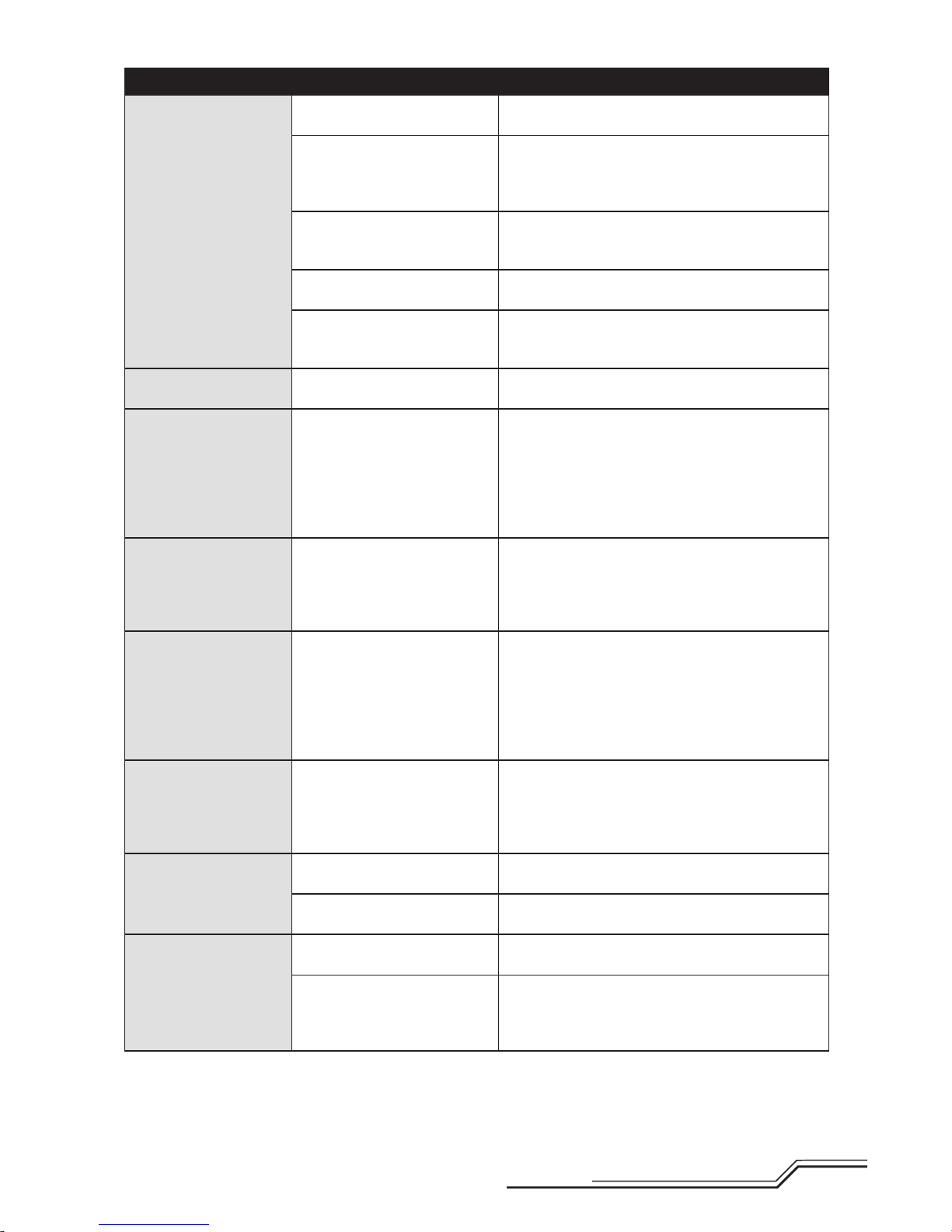
Problem Possible Cause Solution
LED on the receiver fl ashes
rapidly and the helicopter
will not respond to the
transmitter (after binding).
The receiver LED may be
diffi cult to see within the
fuselage
The bind plug was not removed
from the receiver after binding
Disconnect the fl ight battery, remove the bind plug
from the receiver and reconnect the fl ight battery
Less than a 5-second wait
between fi rst powering on the
transmitter and connecting the
fl ight battery to the helicopter
Leave the transmitter powered on. Disconnect and
reconnect the fl ight battery to the helicopter
The helicopter is bound to a
different model memory
(ModelMatch™ transmitters only)
Select the correct model memory on the transmitter.
Disconnect and reconnect the fl ight battery to the
helicopter
Flight battery or transmitter
battery charge is too low
Replace or recharge batteries
Aircraft or transmitter is too close
to large metal object, wireless
source or another transmitter
Move aircraft and transmitter to another
location and attempt connecting again
Helicopter vibrates or
shakes in fl ight
Damaged rotor blades, spindle or
blade grips
Check main rotor blades and blade grips for cracks or
chips. Replace damaged parts. Replace bent spindle
Random movements in
fl ight
Vibration
Verify the receiver is properly attached to the
helicopter. Inspect mounting tape for damage. Verify
that no wires are contacting the receiver. Inspect and
balance all rotating components. Verify the main shaft
and tail rotor adapter are not damaged or bent. Inspect
mechanics for broken or damaged parts and replace
as necessary
Tail oscillation/wag or poor
performance
Damaged tail rotor, main gear
mesh, loose bolts, vibration
Inspect the tail rotor for damage. Verify that all bolts
on the tail assembly are properly tightened. Verify
main gear mesh and ensure no tight spots in the mesh
through full rotation. Replace any damaged or worn
components
Drift in calm winds
Vibration, damaged linkage,
damaged servo
Under normal operation the transmitter trims should
not require adjustment and the center positions are
memorized during initialization. If you fi nd that trim
adjustments are necessary after take off, verify the
balance of all rotating components, ensure the
linkages are not damaged and make sure the servos
are in proper working condition
Drift in wind Normal
The model will drift with the wind but should remain
level in fl ight. Simply hold the cyclic stick in the necessary position to keep the model stationary. The model
must lean into the wind to remain stationary, if the
model remains level then it will drift with the wind
Panic Recovery or Return
to Level does not level the
model
Model was not initialized on a
level, still surface
Re-initialize the model on a level and still surface
Model was not taken off of a level
surface
Always lift off from a level surface
Severe vibration
Battery strapped too tightly
to the model
Loosen the battery strap
Rotating component out of
balance
Check the main shaft, tail rotor, main rotor blades, main
frame and adapter for damage, replace as necessary.
Vibration must be minimized for Panic Recovery and
Return to Level functions to work properly
Page 18
18
EN
22
20
20
2
1
3
45
16
18
7
16
14
17
11
10
13
12
12
18
24
24
25
15
19
9
8
8
8
6
20
21
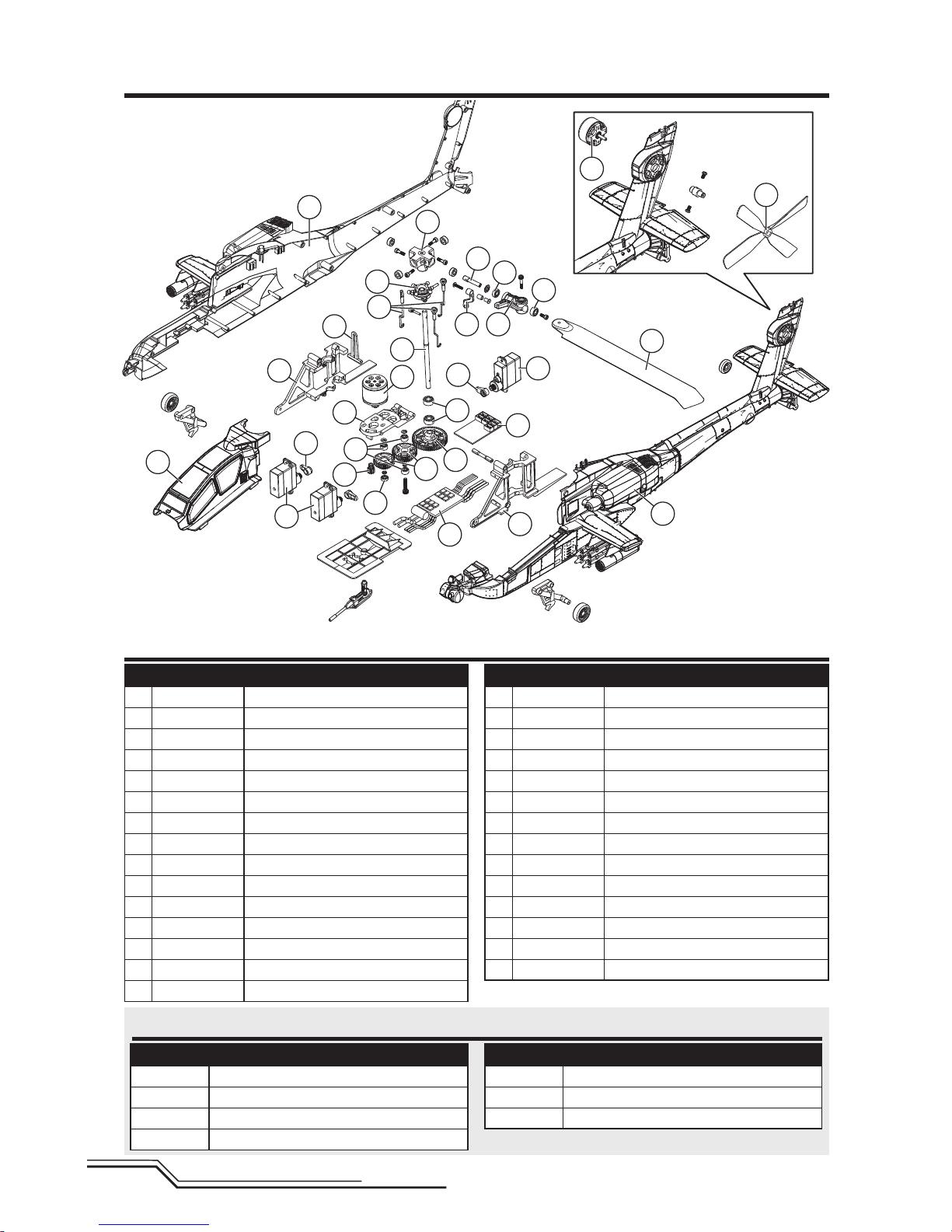
Exploded View
Parts Listings
Part # Description
BLH2500 Micro Apache AH-64, RTF
BLH2580 Micro Apache AH-64, BNF
1 BLH2501 Main rotor blade set: Apache AH-64
2 BLH2502 Main rotor head: Apache AH-64
3 BLH2503 Spindle set: Apache AH-64
4 BLH2504 Main rotor grip set: Apache AH-64
5 BLH2505 Rotor head linkage set: Apache AH-64
6 BLH2506 Swashplate: Apache AH-64
7 BLH2507 Ball Bearing m2.5x6x1.8: Apache AH-64
8 BLH2508 Ball Bearing m2.5x6x2.5: Apache AH-64
9 BLH2509 Ball Bearing m3x7x3: Apache AH-64
10 BLH2510 Servo linkage set: Apache AH-64
11 BLH2511 Main Shaft: Apache AH-64
12 BLH2512 Main frame set: Apache AH-64
13 BLH2513 Anti-rotation bracket: Apache AH-64
Part # Description
14 BLH2514 Motor mount: Apache AH-64
15 BLH2515 Main gear: Apache AH-64
16 BLH2516 Gear drive reduction set: Apache AH-64
17 BLH2517 Brushless main motor: Apache AH-64
18 BLH2518 Servo arm set: Apache AH-64
19 BLH2519 Dual Brushless ESC: Apache AH-64
20 BLH2520 Body set w/led: Apache AH-64
21 BLH2521 Brushless tail motor: Apache AH-64
22 BLH2522 Tail rotor: Apache AH-64
23 EFLB4002S30J 400mAh 2S 7.4V 30C LiPo JST
24 SPMSH2060 Nanolite High Speed Heli Servo
25 SPMAR6335 6-Channel AS3X
®
Nanolite Receiver
EFLC3110 2-3 Cell LiPo Balancing Charger, 0.65A
EFLC4000 AC to 12VDC, 1.5-Amp Power Supply
Optional Parts
Part # Description
DX6i DSMX 6-Channel Transmitter Only
DX7s DSMX 7-Channel Transmitter Only
DX6 DSMX 6-Channel Transmitter Only
DX7 DSMX 7-Channel Transmitter Only
Part # Description
DX8 DSMX 8-Channel Transmitter Only
DX9 DSMX 9-Channel Transmitter Only
DX18 DSMX 18-Channel Transmitter Only
Page 19

19
EN
Limited Warranty
What this Warranty Covers
Horizon Hobby, LLC, (Horizon) warrants to the original purchaser
that the product purchased (the “Product”) will be free from
defects in materials and workmanship at the date of purchase.
What is Not Covered
This warranty is not transferable and does not cover (i) cosmetic
damage, (ii) damage due to acts of God, accident, misuse,
abuse, negligence, commercial use, or due to improper use,
installation, operation or maintenance, (iii) modifi cation of or to
any part of the Product, (iv) attempted service by anyone other
than a Horizon Hobby authorized service center, (v) Product not
purchased from an authorized Horizon dealer, (vi) Product not
compliant with applicable technical regulations, or (vii) use that
violates any applicable laws, rules, or regulations.
OTHER THAN THE EXPRESS WARRANTY ABOVE, HORIZON
MAKES NO OTHER WARRANTY OR REPRESENTATION, AND
HEREBY DISCLAIMS ANY AND ALL IMPLIED WARRANTIES,
INCLUDING, WITHOUT LIMITATION, THE IMPLIED WARRANTIES
OF NON-INFRINGEMENT, MERCHANTABILITY AND FITNESS FOR
A PARTICULAR PURPOSE. THE PURCHASER ACKNOWLEDGES
THAT THEY ALONE HAVE DETERMINED THAT THE PRODUCT
WILL SUITABLY MEET THE REQUIREMENTS OF THE
PURCHASER’S INTENDED USE.
Purchaser’s Remedy
Horizon’s sole obligation and purchaser’s sole and exclusive
remedy shall be that Horizon will, at its option, either (i)
service, or (ii) replace, any Product determined by Horizon to
be defective. Horizon reserves the right to inspect any and all
Product(s) involved in a warranty claim. Service or replacement
decisions are at the sole discretion of Horizon. Proof of
purchase is required for all warranty claims. SERVICE OR
REPLACEMENT AS PROVIDED UNDER THIS WARRANTY IS THE
PURCHASER’S SOLE AND EXCLUSIVE REMEDY.
Limitation of Liability
HORIZON SHALL NOT BE LIABLE FOR SPECIAL, INDIRECT,
INCIDENTAL OR CONSEQUENTIAL DAMAGES, LOSS OF
PROFITS OR PRODUCTION OR COMMERCIAL LOSS IN ANY
WAY, REGARDLESS OF WHETHER SUCH CLAIM IS BASED IN
CONTRACT, WARRANTY, TORT, NEGLIGENCE, STRICT LIABILITY
OR ANY OTHER THEORY OF LIABILITY, EVEN IF HORIZON HAS
BEEN ADVISED OF THE POSSIBILITY OF SUCH DAMAGES.
Further, in no event shall the liability of Horizon exceed the
individual price of the Product on which liability is asserted.
As Horizon has no control over use, setup, fi nal assembly,
modifi cation or misuse, no liability shall be assumed nor
accepted for any resulting damage or injury. By the act of use,
setup or assembly, the user accepts all resulting liability. If you
as the purchaser or user are not prepared to accept the liability
associated with the use of the Product, purchaser is advised to
return the Product immediately in new and unused condition to
the place of purchase.
Law
These terms are governed by Illinois law (without regard to
confl ict of law principals). This warranty gives you specifi c legal
rights, and you may also have other rights which vary from state
to state. Horizon reserves the right to change or modify this
warranty at any time without notice.
WARRANTY SERVICES
Questions, Assistance, and Services
Your local hobby store and/or place of purchase cannot
provide warranty support or service. Once assembly, setup or
use of the Product has been started, you must contact your
local distributor or Horizon directly. This will enable Horizon to
better answer your questions and service you in the event that
you may need any assistance. For questions or assistance,
please visit our website at www.horizonhobby.com, submit a
Product Support Inquiry, or call the toll free telephone number
referenced in the Warranty and Service Contact Information
section to speak with a Product Support representative.
Inspection or Services
If this Product needs to be inspected or serviced and is
compliant in the country you live and use the Product in,
please use the Horizon Online Service Request submission
process found on our website or call Horizon to obtain a Return
Merchandise Authorization (RMA) number. Pack the Product
securely using a shipping carton. Please note that original boxes
may be included, but are not designed to withstand the rigors
of shipping without additional protection. Ship via a carrier that
provides tracking and insurance for lost or damaged parcels, as
Horizon is not responsible for merchandise until it arrives and is
accepted at our facility. An Online Service Request is available
at http://www.horizonhobby.com/content/_service-center_
render-service-center. If you do not have internet access, please
contact Horizon Product Support to obtain a RMA number along
with instructions for submitting your product for service. When
calling Horizon, you will be asked to provide your complete
name, street address, email address and phone number where
you can be reached during business hours. When sending
product into Horizon, please include your RMA number, a list
of the included items, and a brief summary of the problem. A
copy of your original sales receipt must be included for warranty
consideration. Be sure your name, address, and RMA number
are clearly written on the outside of the shipping carton.
NOTICE: Do not ship Li-Po batteries to Horizon. If you have
any issue with a Li-Po battery, please contact the appropriate
Horizon Product Support offi ce.
Warranty Requirements
For Warranty consideration, you must include your
original sales receipt verifying the proof-of-purchase
date. Provided warranty conditions have been met, your
Product will be serviced or replaced free of charge. Service or
replacement decisions are at the sole discretion of Horizon.
Non-Warranty Service
Should your service not be covered by warranty, service
will be completed and payment will be required without
notifi cation or estimate of the expense unless the
expense exceeds 50% of the retail purchase cost. By
submitting the item for service you are agreeing to payment of
the service without notifi cation. Service estimates are available
upon request. You must include this request with your item
submitted for service. Non-warranty service estimates will
be billed a minimum of ½ hour of labor. In addition you will
be billed for return freight. Horizon accepts money orders
and cashier’s checks, as well as Visa, MasterCard, American
Express, and Discover cards. By submitting any item to Horizon
for service, you are agreeing to Horizon’s Terms and Conditions
found on our website http://www.horizonhobby.com/content/_
service-center_render-service-center.
ATTENTION: Horizon service is limited to Product
compliant in the country of use and ownership. If
received, a non-compliant Product will not be serviced.
Further, the sender will be responsible for arranging
return shipment of the un-serviced Product, through
a carrier of the sender’s choice and at the sender’s
expense. Horizon will hold non-compliant Product for a
period of 60 days from notifi cation, after which it will be
discarded.
Page 20
20
EN
Warranty and Service Contact Information
Country of
Purchase
Horizon Hobby Contact Information Address
United States of
America
Horizon Service Center
(Repairs and Repair Requests)
servicecenter.horizonhobby.
com/RequestForm/
4105 Fieldstone Rd
Champaign, Illinois, 61822 USA
Horizon Product Support
(Product Technical Assistance)
www.quickbase.com/db/
bghj7ey8c?a=GenNewRecord
888-959-2304
Sales
sales@horizonhobby.com
888-959-2304
United Kingdom
Service/Parts/Sales:
Horizon Hobby Limited
sales@horizonhobby.co.uk
Units 1–4 , Ployters Rd, Staple Tye
Harlow, Essex, CM18 7NS, United
Kingdom
+44 (0) 1279 641 097
Germany
Horizon Technischer Service service@horizonhobby.de
Christian-Junge-Straße 1
25337 Elmshorn, Germany
Sales: Horizon Hobby GmbH +49 (0) 4121 2655 100
France
Service/Parts/Sales:
Horizon Hobby SAS
infofrance@horizonhobby.com
11 Rue Georges Charpak
77127 Lieusaint, France
+33 (0) 1 60 18 34 90
China
Service/Parts/Sales:
Horizon Hobby – China
info@horizonhobby.com.cn
Room 506, No. 97 Changshou Rd.
Shanghai, China 200060
+86 (021) 5180 9868
Compliance Information for the European Union
EU Compliance Statement:
Horizon Hobby, LLC hereby declares that this
product is in compliance with the essential
requirements and other relevant provisions of
the R&TTE, EMC, and LVD Directives.
A copy of the EU Declaration of Conformity is available
online at: http://www.horizonhobby.com/content/supportrender-compliance.
Instructions for disposal of WEEE by users in the European Union
This product must not be disposed of with
other waste. Instead, it is the user’s responsibility to dispose of their waste equipment
by handing it over to a designated collections
point for the recycling of waste electrical and
electronic equipment. The separate collection
and recycling of your waste equipment at the
time of disposal will help to conserve natural resources and
make sure that it is recycled in a manner that protects human
health and the environment. For more information about where
you can drop off your waste equipment for recycling, please
contact your local city offi ce, your household waste disposal
service or where you purchased the product.
FCC Information
This device complies with part 15 of the FCC rules.
Operation is subject to the following two conditions:
(1) This device may not cause harmful interference,
and (2) this device must accept any interference received,
including interference that may cause undesired operation.
CAUTION: Changes or modifi cations not ex-
pressly approved by the party responsible for
compliance could void the user’s authority to operate the
equipment.
This product contains a radio transmitter with wireless technology which has been tested and found to be
compliant with the applicable regulations governing a radio
transmitter in the 2.400GHz to 2.4835GHz frequency range.
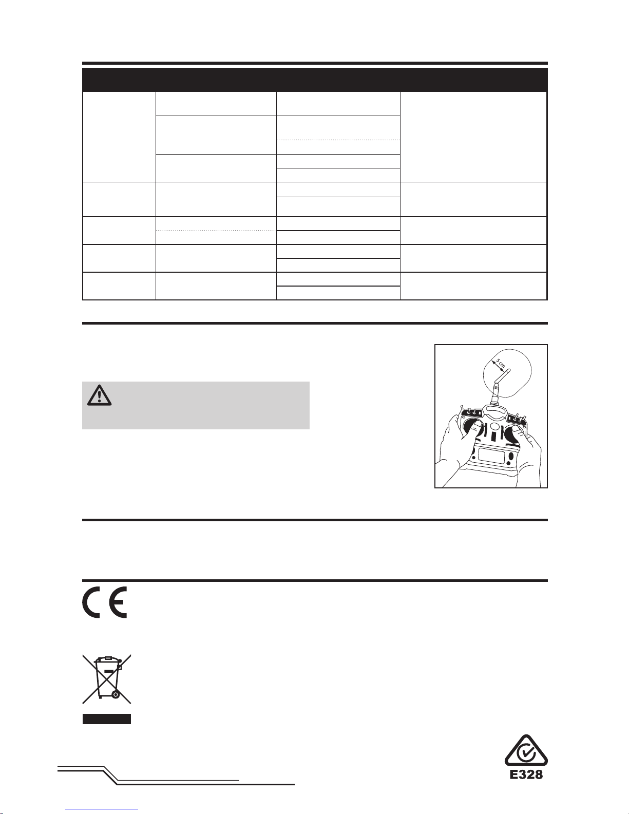
Antenna Separation Distance
When operating your
Spektrum transmitter,
please be sure to maintain
a separation distance of at
least 5 cm between your
body (excluding fi ngers,
hands, wrists, ankles and
feet) and the antenna to
meet RF exposure safety
requirements as determined
by FCC regulations.
The following illustrations
show the approximate
5 cm RF exposure area and
typical hand placement
when operating your Spektrum transmitter.
IC Information
This device complies with Industry Canada license-exempt
RSS standard(s). Operation is subject to the following two
conditions:
(1) this device may not cause interference, and (2) this
device must accept any interference, including interference
that may cause undesired operation of the device.
Page 21
21
DE
WARNUNG: Lesen Sie die GESAMTE Bedienungsanleitung, um sich vor dem Betrieb mit den Produktfunktionen
vertraut zu machen. Wird das Produkt nicht korrekt betrieben, kann dies zu Schäden am Produkt oder persönli-
chem Eigentum führen oder schwere Verletzungen verursachen.
Dies ist ein hochentwickeltes Hobby-Produkt. Es muss mit Vorsicht und gesundem Menschenverstand betrieben werden
und benötigt gewisse mechanische Grundfähigkeiten. Wird dieses Produkt nicht auf eine sichere und verantwortungsvolle Weise betrieben, kann dies zu Verletzungen oder Schäden am Produkt oder anderen Sachwerten führen. Dieses
Produkt eignet sich nicht für die Verwendung durch Kinder ohne direkte Überwachung eines Erwachsenen. Versuchen
Sie nicht ohne Genehmigung durch Horizon Hobby, LLC das Produkt zu zerlegen, es mit inkompatiblen Komponenten
zu verwenden oder auf jegliche Weise zu erweitern. Diese Bedienungsanleitung enthält Anweisungen für Sicherheit,
Betrieb und Wartung. Es ist unbedingt notwendig, vor Zusammenbau, Einrichtung oder Verwendung alle Anweisungen
und Warnhinweise im Handbuch zu lesen und zu befolgen, damit es bestimmungsgemäß betrieben werden kann und
Schäden oder schwere Verletzungen vermieden werden.
• Halten Sie stets in allen Richtungen einen Sicherheitsabstand um Ihr Modell, um Zusammenstöße oder Verletzungen zu vermeiden. Dieses Modell wird von einem
Funksignal gesteuert, das Interferenzen von
vielen Quellen außerhalb Ihres Einfl ussbereiches unterliegt. Diese Interferenzen können einen augenblicklichen
Steuerungsverlust verursachen.
• Betreiben Sie Ihr Modell immer auf einer Freifl äche ohne
Fahrzeuge in voller Größe, Verkehr oder Menschen.
• Befolgen Sie stets sorgfältig die Anweisungen und
Warnhinweise für das Modell und jegliche optionalen
Hilfsgeräte (Ladegeräte, Akkupacks usw.).
• Bewahren Sie alle Chemikalien, Klein- und Elektroteile
stets außerhalb der Reichweite von Kindern auf.
• Setzen Sie Geräte, die für diesen Zweck nicht speziell
ausgelegt und geschützt sind, niemals Wasser aus.
Feuchtigkeit kann die Elektronik beschädigen.
• Stecken Sie keinen Teil des Modells in den Mund, da dies
zu schweren Verletzungen oder sogar zum Tod führen
kann.
• Betreiben Sie Ihr Modell nie mit fast leeren Senderakkus.
• Halten Sie das Fluggerät immer in Sicht und unter
Kontrolle.
• Gehen Sie sofort auf Motor Aus bei Rotorberührung.
• Verwenden Sie immer vollständig geladene Akkus.
• Lassen Sie immer den Sender eingeschaltet wenn das
Fluggerät eingeschaltet ist.
• Nehmen Sie vor der Demontage des Fluggerätes die
Akkus heraus.
• Halten Sie bewegliche Teile immer sauber.
• Halten Sie die Teile immer trocken.
• Lassen Sie Teile immer erst abkühlen bevor Sie sie
anfassen.
• Nehmen Sie die Akkus/Batterien nach Gebrauch heraus.
• Betreiben Sie Ihr Fluggerät niemals mit beschädigter
Verkabelung.
• Fassen Sie niemals bewegte Teile an.
HINWEIS
Spezielle Bedeutungen
Alle Anweisungen, Garantien und anderen zugehörigen Dokumente können im eigenen Ermessen von Horizon Hobby,
LLC jederzeit geändert werden. Die aktuelle Produktliteratur fi nden Sie auf horizonhobby.com unter der Registerkarte
„Support“ für das betreffende Produkt.
Die folgenden Begriffe werden in der gesamten Produktliteratur verwendet, um auf unterschiedlich hohe Gefahrenrisiken beim Betrieb dieses Produkts hinzuweisen:
HINWEIS: Wenn diese Verfahren nicht korrekt befolgt werden, können sich möglicherweise Sachschäden UND
geringe oder keine Gefahr von Verletzungen ergeben.
ACHTUNG: Wenn diese Verfahren nicht korrekt befolgt werden, ergeben sich wahrscheinlich Sachschäden UND die
Gefahr von schweren Verletzungen.
WARNUNG: Wenn diese Verfahren nicht korrekt befolgt werden, ergeben sich wahrscheinlich Sachschäden,
Kollateralschäden und schwere Verletzungen ODER mit hoher Wahrscheinlichkeit oberfl ächliche Verletzungen.
Sicherheitsvorkehrungen und Warnhinweise
Nicht geeignet für Kinder unter 14 Jahren. Dies ist kein Spielzeug.
WARNUNG GEGEN GEFÄLSCHTE PRODUKTE: Sollten Sie jemals eine Spektrum Komponente ersetzen wollen,
kaufen Sie die benötigen Ersatzteile immer bei Horizon Hobby oder einem von Horizon Hobby autorisiertem
Händler um die hohe Qualität des Produktes zu gewährleisten. Horizon Hobby LLC lehnt jedwede Haftung, Garantie
oder Unterstützung sowie Kompatibilitäts- oder Leistungsansprüche zu DSM oder Spektrum in Zusammenhang mit
gefälschten Produkten ab.
Page 22
22
DE
Lieferumfang
• Blade AH-64 Apache
• 400mAh 2S 7.4V 30 C Li-Po Akku
• E-fl ite 2-3S LiPo Balancer Ladegerät,
0.65A mit AC/DC Adapter
• DXe Sender (nur in RTF version)
• 4 AA Batterien (nur in RTF version)
Inhaltsangabe
Länge
375mm
Höhe
95mm
Hauptrotordurchmesser
318mm
Heckrotordurchmesser
65mm
Fluggewicht
190 g
Spezifikationen
Ausstattung RTF BNF
Rumpf
Blade AH-64 Apache
Inklusive Inklusive
Motor
6000kv Brushless
Eingebaut Eingebaut
Heckmotor
4800k Brushless
Eingebaut Eingebaut
Empfänger
Spektrum AR6335
Eingebaut Eingebaut
Regler / ESC
Dual Brushless
Eingebaut Eingebaut
Akku
400mAh 2S 7.4V 30 C Li-Po
Inklusive Inklusive
Ladegerät
2-3S 0.65A LiPo Balancing Ladegerät mit AC/ DC Adapter
Inklusive Inklusive
Sender
DSM2/DSMX kompatibler Sender
Inklusive DXe Erforderlich
Sie können Ihr Produkt online unter
www.bladehelis.com registrieren.
Lieferumfang .................................................................. 22
Vorbereitung für den Erstfl ug .......................................... 23
Checkliste zum Fliegen ................................................... 23
Akku-Warnhinweise ........................................................ 23
Laden des Flugakkus ...................................................... 23
Einsetzen der Senderbatterien (RTF) ...............................24
DXe Senderkontrollen (RTF) ............................................24
Sendereinstellungen (BNF) .............................................. 25
Einsetzen des Flugakkus ................................................. 27
Binden von Sender und Empfänger ................................. 27
SAFE Technologie ........................................................... 28
Flugmodes und Dual Rates .............................................28
Panikrettung ................................................................... 28
Throttle Hold (Autorotation) ............................................. 29
Kontrolltests....................................................................29
Einführung in die Hauptsteuerfunktionen......................... 30
Fliegen des AH-64 Apache .............................................. 31
Erweiterte Einstellungen .................................................31
Servoeinstellung ............................................................ 33
Trimmfl ug ....................................................................... 34
Kontrollen nach dem Flug und Wartung ........................... 35
Leitfaden zur Problemlösung ........................................... 35
Explosionszeichnung....................................................... 37
Teileliste ......................................................................... 37
Optionsteile .................................................................... 37
Garantie und Service Informationen ................................ 38
Garantie und Service Kontaktinformationen..................... 39
Rechtliche Informationen für die Europäische Union ........ 39
Page 23
23
DE
HINWEIS: Laden Sie nur Akkus die kühl genug zum
Anfassen und unbeschädigt sind. Bitte prüfen Sie den
Akku um sicher zu stellen, dass er nicht beschädigt,
angeschwollen, verbogen, gebrochen und punktiert ist.
1. Schließen Sie den AC/DC Adapter an ein AC Netzgerät an.
2. Schließen Sie den AC/DC Adapter an das Ladegerät an.
3. Schließen Sie den Balancerstecker an das Ladegerät an.
Der Stecker ist gegen Verpolung geschützt.
4. Trennen Sie immer den Flugakku nach erfolgter Ladung
sofort vom Ladegerät.
LED Indikatoren
Rote LED blinkt.: Ladegerät eingeschaltet, kein Akku
angeschlossen
Rote und grüne LED´s leuchten: Akku angeschlossen
und lädt
Rote LED leuchtet: fertig geladen
Rote und grüne LED´s blinken: Fehleranzeige Ladegerät
Das Aufl aden eines entladenen (nicht tiefentladen) 400mAh
Batterie dauert ca. 30 -45 Minuten. Das Ladegerät kann
auch über die DC Krokodilklemmen mit Strom versorgt
werden. Schließen Sie die Klemmen an eine 11,5 - 15V
DC Stromquelle an und achten bitte dabei auf die richtige
Polarität.
ACHTUNG: Betreiben Sie das Ladegerät nicht mit
dem AC und DC-Anschluß zur gleichen Zeit. Hier
könnte ein Kurzschluß entstehen bei dem das Produkt
beschädigt wird. Dieses könnte Körper- und Sachbeschädigungen zur Folge haben.
HINWEIS: Schließen Sie die Kabel immer polrichtig an.
Lesen Sie bitte dazu die Bedienungsanleitung des Akkus,
das Sicherheitsdatenblatt oder kontaktieren den Kundenservice bevor Sie das Ladegerät mit anderen Stromquellen
als dem Standard-AC-Netzteil betreiben.
Laden des Flugakkus
ACHTUNG: Alle Anweisungen und Warnhinweise
müssen genau befolgt werden. Falsche Handhabung
von Li-Po-Akkus kann zu Brand, Personen- und/oder Sachwertschäden führen.
• LASSEN SIE LADEN VON AKKUS UNBEAUFSICHTIGT.
• LADEN SIE NIEMALS AKKUS ÜBER NACHT.
• Durch Handhabung, Aufl adung oder Verwendung des mitgelieferten Li-Po-Akkus übernehmen Sie alle mit Lithiumakkus
verbundenen Risiken.
• Sollte der Akku zu einem beliebigen Zeitpunkt beginnen, sich
aufzublähen oder anzuschwellen, stoppen Sie die Verwendung
unverzüglich. Falls dies beim Laden oder Entladen auftritt,
stoppen Sie den Lade-/Entladevorgang, und entnehmen Sie
den Akku. Wird ein Akku, der sich aufbläht oder anschwillt,
weiter verwendet, geladen oder entladen, besteht Brandgefahr.
• Lagern Sie den Akku stets bei Zimmertemperatur an einem
trockenen Ort.
• Bei Transport oder vorübergehender Lagerung des Akkus
muss der Temperaturbereich zwischen 40°F und 120°F
(ca. 5 – 49°C) liegen. Akku oder Modell dürfen nicht im Auto
oder unter direkter Sonneneinstrahlung gelagert werden. Bei
Lagerung in einem heißen Auto kann der Akku beschädigt
werden oder sogar Feuer fangen.
• Laden Sie die Akkus immer weit entfernt von brennbaren
Materialien.
• Überprüfen Sie immer den Akku vor dem Laden und laden Sie
niemals defekte oder beschädigte Akkus.
• Verwenden Sie ausschließlich ein Ladegerät das speziell für
das Laden von LiPo Akku geeignet ist. Das Laden mit einem
nicht geeignetem Ladegerät kann Feuer und / oder Sachbeschädigung zur Folge haben.
• Überwachen Sie ständig die Temperatur des Akkupacks
während des Ladens.
• Trennen Sie immer den Akku nach dem Laden und lassen das
Ladegerät abkühlen.
• Entladen Sie niemals ein LiPo Akku unter 3V pro Zelle unter
Last.
• Verdecken Sie niemals Warnhinweise mit Klettband.
• Lassen Sie niemals Akkus während des Ladens unbeaufsichtigt.
• Laden Sie niemals Akkus ausserhalb ihrer sicheren Grenzen.
• Laden Sie nur Akkus die kühl genug zum anfassen sind.
• Versuchen Sie nicht das Ladegerät zu demontieren oder zu
verändern.
• Lassen Sie niemals Minderjährige Akkus laden.
• Laden Sie niemals Akkus an extrem kalten oder heißen
Plätzen (empfohlener Temperaturbereich 5 – 49°) oder im
direkten Sonnenlicht.
Akku-Warnhinweise
Vorbereitung für den Erstfl ug
• Entnehmen und überprüfen Sie die Komponenten
• Laden Sie den Flugakku
• Programmieren Sie Ihren Sender (nur BNF Version)
• Setzen Sie den Akku ein wenn er vollständig geladen ist
• Binden von Sender (nur BNF Version)
• Machen Sie sich mit den Kontrollen vertraut
• Finden Sie eine geeignete Fläche zum fl iegen
Checkliste zum Fliegen
❏ Schalten Sie immer den Sender zuerst ein
❏ Stecken Sie den Flugakku an den Anschluß der ESC
❏ Lassen Sie der ESC Kontrolleinheit Zeit zum initialisieren
und armieren
❏ Fliegen Sie das Modell
❏ Landen Sie das Modell
❏ Stecken Sie den Flugakku von der ESC
❏ Schalten Sie immer den Sender als letztes aus
Page 24
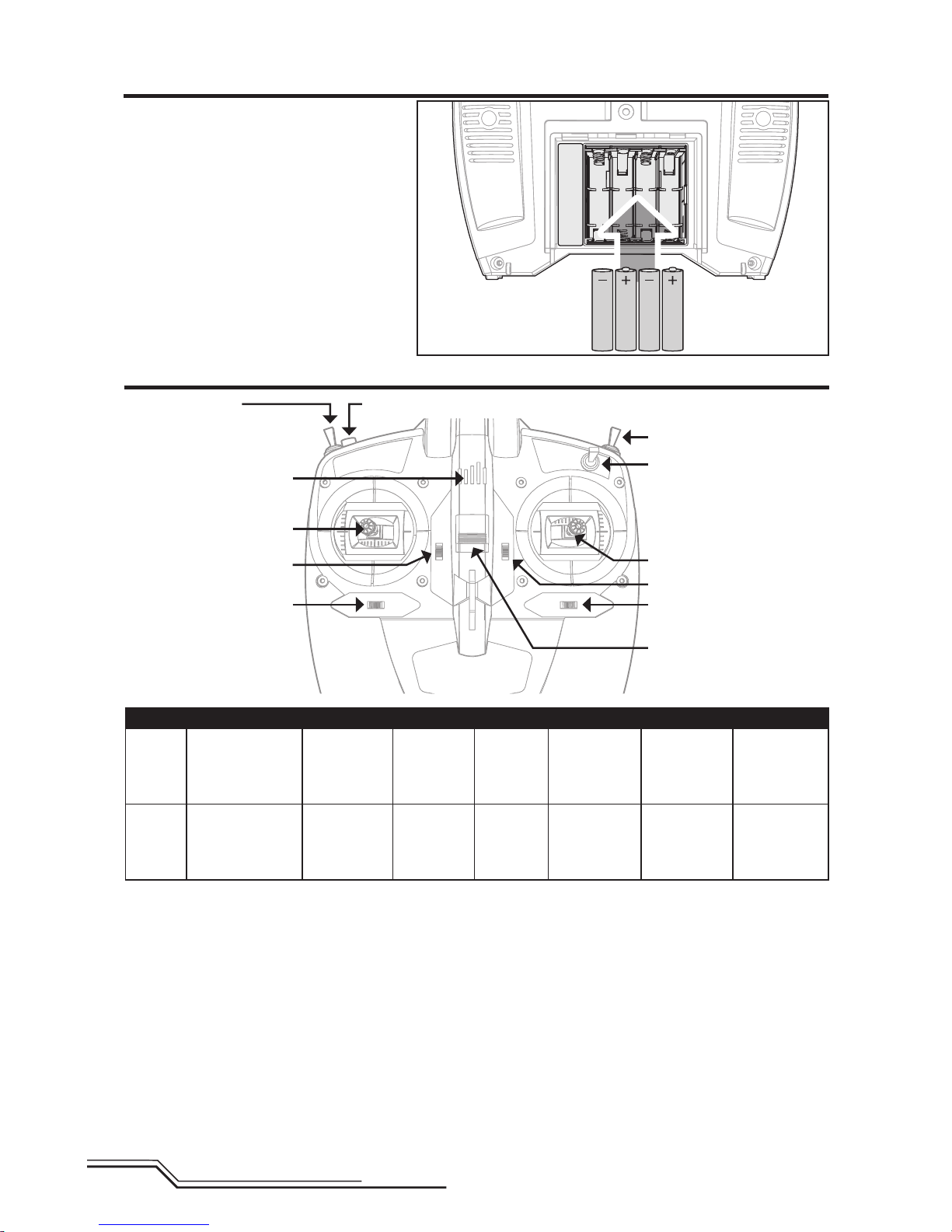
24
DE
Einsetzen der Senderbatterien (RTF)
Die LED- Anzeigen blinken schneller und der
Sender beginnt zu piepen wenn die Batteriespannung sinkt.
Ersetzen Sie die Senderbatterien wenn der
Sender zu piepen beginnt.
Flugmodeschalter
0 = Stability Mode (NORM)
1 = Fortgeschrittener Mode (FM1)
2 = Agility Mode (FM2)
Binde / Panik Schalter
Gas Aus (Throttle Hold)
Dual Rate Schalter
DXe Senderkontrollen (RTF)
A
B
C
D
E
F
G
LED Indicator
ABCDEFG
Modus 1
Querruder
(links/rechts)
Gas (auf/ab)
Gas trimm
Querrudertrimm
EIN/AUSSchalter
Seitenrudertrimm
Höhenrudertrimm
Seitenruder
(links/rechts)
Höhenruder
(auf/ab)
Modus 2
Querruder
(links/rechts)
Höhenruder
(auf/ab)
Höhenrudertrimm
Querrudertrimm
EIN/AUSSchalter
Seitenrudertrimm
Gas trimm
Seitenruder
(links/rechts)
Gas (auf/ab)
Page 25

25
DE
Sendereinstellungen (BNF)
D/R & Expo
Chan
Schalter Pos
(Ail D/R) D/R Expo
AILE
0 100/100 +25
1 100/100 +25
2 75/75 +25
ELEV
0 100/100 +25
1 100/100 +25
2 75/75 +25
RUDD
0 100/100 +25
1 100/100 +25
2 75/75 +25
D/R & Expo
Chan Sw Pos D/R Expo
AILE
0 100 +25
1 75 +25
ELEV
0 100 +25
1 75 +25
RUDD
0 100 +25
1 75 +25
Mix 1
GYRO->GYRO ACT
Rate D+125% U+125%
SW ELE D/R TRIM – INH
Timer
Mode Count Down
Time 5:00 Tone
Start Gas über
Over 25%
Timer
Down Timer 5:00
Switch THR CUT
Systemeinstellung
Modelltyp HELI
Taumels-
cheibentyp
1 servo
Normal
Flugzustand Setup
Flugzustand F Mode
Autorotation Halt
Schalterauswahl
Trainer Aux 2(K7)
F Mode FW
Gyro Aus
Mix Aus
Hold Aus
Knob Aus
Pulsrate
11ms
DSMX
Kanal Servoweg Laufrichtung
Gas 100/100 Normal
ROL 100/100 Normal
NCK 100/100 Normal
HCK 100/100 Normal
Kanal Servoweg Laufrichtung
FW 100/100 Normal
PIT 100/100 Normal
K7 100/100 Normal
Servoeinstellung
Funktionsliste
ADJUST LISTSETUP LIST
DX6i
DX7s, DX8
Throttle Curve
Switch Pos
(F Mode)
Pos 1Pos 2Pos 3Pos 4Pos
5
NORM 0 25 50 75 100
STUNT 100 90 85 90 100
HOLD 0
Gaskurve
Schalter Pos
(F Mode) Pt 1 Pt 2 Pt 3 Pt 4 Pt 5
N 0 25 50 75 100
1 100 80 75 80 100
2 100 90 85 90 100
TRAVEL ADJ
Channel Travel
THRO 100/100
AILE 100/100
ELEV 100/100
RUDD 100/100
GYRO 100/100
PITC 100/100
REVERSE
Channel Direction
THRO N
AILE N
ELEV N
RUDD N
GYRO N
PITC R
GYRO
RATE SW-F.MODE
0 88% NORM 0
1 12% STUNT 1
Modulations Einstellung
AUTO DSMX-ENABLE
D/R COMBI
D/R SW AILE
Model Type HELI
Swash Type
1 servo
Normal
Pitch Curve
Switch Pos
(F Mode)
Pos 1Pos 2Pos 3Pos 4Pos
5
NORM 30 40 50 75 100
STUNT 0 25 50 75 100
HOLD 25 37 50 75 100
Pitch Curve
Schalter Pos
(F Mode) Pt 1 Pt 2 Pt 3 Pt 4 Pt 5
N 30 40 50 75 100
1 0 25 50 75 100
2 0 25 50 75 100
HOLD 25 37 50 75 100
Panik Modeschalter
ELEV D/R Schalter
Schalter Pos 0 = Panikmode Aus
Schalter Pos 1 = Panikmode Ein
Panikmode Funktion
Trainer Binde Button
Gedrückt = Panik Mode Ein
Gelöst = Panikmode Aus
Gas Aus
Throttle 0%
Gyro
AUS
Hat sich das Modell wieder ausgerichtet,
müssen sie den Panikmode manuell wieder
ausschalten. Schalten Sie den Schalter in die
Aus Position, da sonst die Taumelscheibenund Heckrotorfunktionen reduziert sind.
Page 26

26
DE
D/R & Expo
Kanal Sch. (F) Pos D/R Expo
ROL
0 100/100 +25
1 75/75 +25
NCK
0 100/100 +25
1 75/75 +25
HCK
0 100/100 +25
1 75/75 +25
Kreisel
Aus
D/R & Expo
Kanal Sch. (F) Pos D/R Expo
ROL
0 100/100 +25
1 100/100 +25
2 75/75 +25
NCK
0 100/100 +25
1 100/100 +25
2 75/75 +25
HCK
0 100/100 +25
1 100/100 +25
2 75/75 +25
Kreisel
Aus
Mischer
P-Mix 1
Normal
Kanäle I > FW
Rate 0/ –125
Offset 100
Schalter Schalter I
Position 0
1
Timer
Mode Herunterzählen
Time 5:00
Start Gasknüppel
Over 25%
One Time Aus
Systemeinstellung
Modelltyp HELI
Taumels-
cheibentyp
Normal
Flugzustand
Schalter 1 Switch B
Autorot.
Schalter
Switch H
0
1
Kanalzuweisung
Eingabekanal
1 Throttle
2 Aileron
3 Elevator
4 Rudder
5 Fw Schalter B
6 Collective
Pulsrate
11ms
DSMX
Systemeinstellung
Modelltyp HELI
Taumels-
cheibentyp
Normal
Flugzustand
Schalter 1 Schalter B
Schalter 2 Aus
Autorot.
Schalter
Schalter H
0
1
Kanalzuweisung
Eingabekanal
1 Throttle
2 Aileron
3 Elevator
4 Rudder
5 Fw Schalter B
6 Collective
7 AUX 2 Schalter I
Pulsrate
11ms
DSMX
Kanal Servoweg Laufrichtung
GAS 100/100 Normal
ROL 100/100 Normal
NCK 100/100 Normal
Kanal Servoweg Laufrichtung
HCK 100/100 Normal
FW 100/100 Normal
PIT 100/100 Normal
Kanal Servoweg Laufrichtung
GAS 100/100 Normal
ROL 100/100 Normal
NCK 100/100 Normal
HCK 100/100 Normal
FW 100/100 Normal
Kanal Servoweg Laufrichtung
PIT 100/100 Normal
AX2 100/100 Normal
AX3 100/100 Normal
AX4 100/100 Normal
Servoeinstellung
Servoeinstellung
Funktionsliste
Funktionsliste
DX6
DX7 (neu), DX9, DX18
Panikmode Funktion
Binde / I Button
Gedrückt = Panik Mode Ein
Gelöst = Panikmode Aus
Panikmode Funktion
Binde / I Button
Gedrückt = Panikmode Ein
Gelöst = Panikmode Aus
Uhr
Mode Herunterzählen
Zeit 5:00
Start Gasknüppel
Über 25%
Einmal Aus
Gaskurve
Sch. (B) Pos Pt 1 Pt 2 Pt 3 Pt 4 Pt 5
N 0 25 50 75 100
1 100 80 75 80 100
2 100 90 85 90 100
HOLD 0 0 0 0 0
Gaskurve
Sch. (B) Pos Pt 1 Pt 2 Pt 3 Pt 4 Pt 5
N 0 25 50 75 100
1 100 80 75 80 100
2 100 90 85 90 100
HOLD 0 0 0 0 0
Pitchkurve
Sch. (B) Pos Pt 1 Pt 2 Pt 3 Pt 4 Pt 5
N 30405075100
1 0 25 50 75 100
2 0 25 50 75 100
HOLD 25 37 50 75 100
Pitchkurve
Sch. (B) Pos Pt 1 Pt 2 Pt 3 Pt 4 Pt 5
N 30 40 50 75 100
1 0 25 50 75 100
2 0 25 50 75 100
HOLD 25 37 50 75 100
Page 27

27
DE
Um ihren Hubschrauber an den gewählten Sender zu binden oder neu zu binden folgen Sie bitte
den untenstehenden Anweisungen.
Der Bindevorgang
1. Trennen Sie den Flugakku vom Hubschrauber.
2. Entnehmen Sie aus der Sendereinstelltabelle die korrekte Einstellung für ihren Sender.
3. Bringen Sie den Gashebel in die niedrigste Position. Stellen Sie alle Trimmungen in die Mitte.
4. Schalten Sie den Sender aus und alle Schalter in die 0 Position. Stellen Sie das Gas in die Niedrig / Motor Aus Position.
5. Setzen Sie den Bindestecker in die Bindesteckerverlängerung unter der Haube.
6. Schließen Sie den Flugakku an den Regler an.
7. Aktivieren Sie den Bindenmode des Senders währen Sie ihn einschalten.
8. Lassen Sie den Bindeschalter nach 2-3 Sekunden los. Der Hubschrauber ist dann gebunden wenn die Taumelscheibe auf die Bewegungen des Steuerhebel reagiert.
9. Trennen Sie den Flugakku und schalten den Sender aus.
ACHTUNG: Wenn Sie einen Futaba-Sender mit einem Spektrum DSM-Modul verwenden, müssen Sie den
Gaskanal reversieren (umkehren) und danach das System neu binden. Lesen Sie bitte für den Bindevorgang
und programmieren der Failsafeeinstellungen die Bedienungsanleitung des Spektrum Modules. Zum reversieren des
Gaskanals lesen Sie bitte in der Anleitung des Futaba Senders nach.
Binden von Sender und Empfänger
1. Bringen Sie den Gashebel in die niedrigste Position.
2. Schalten Sie den Sender ein.
3. Zentrieren Sie alle Trimmungen. Bei der in der RTF
Version enthaltene Spektrum DXe sind die Trimmungen zentriert wenn Sie bei dem Drücken des
Trimmbutton einen höheren Ton hören. Bewegen Sie
die Trimmung in beide Richtungen bis Sie diesen Ton
hören.
4. Nehmen Sie die Kabinenhaube nach oben ab.
5. Setzen Sie den Akku wie abgebildet ein. Drücken Sie
die Motorkabel dabei etwas zur Seite und drücken den
Akku nach unten bis er fl ach aufl iegt.
6. Schließen Sie den Akkuanschluß am Regler polrichtig an.
ACHTUNG: Der verpolte Anschluss des Akkus an
den Regler beschädigt den Regler, Akku oder
beides. Schäden die durch falschen Anschluss entstanden sind werden nicht von der Garantie gedeckt.
7. Setzen Sie die Kabinenhaube wieder auf.
HINWEIS: Bitte stellen Sie sicher, dass die Akku- und
Reglerkabel nach dem Einsetzen keinen Kontakt zum
Motor haben. Ein nicht beachten führt zu hohen Motorverschleiss und einem Kabelkurzschluss der einen
Absturz zur Folge hat. Absturzschäden sind nicht
durch die Garantie gedeckt.
8. Stellen Sie den Hubschrauber auf eine ebene
Oberfl äche und lassen ihn still stehen bis der Regler
zwei mal gepiept und damit die erfolgte Initialiserung
anzeigt.
Sollte die Initialisierung nicht wie beschrieben erfolgen,
lesen Sie bitte im Leitfaden zur Problemlösung auf der
Rückseite der Anleitung.
ACHTUNG: Trennen Sie immer den Akku vom
hubschrauber wenn Sie nicht fl iegen um ein
tiefentladen des Akkus zu vermeiden. Akkus die unter
die zulässige Grenze entladen werden können dabei
beschädigt werden, was zu Leistungsverlust und potentieller Brandgefahr beim Laden führen kann.
Einsetzen des Flugakkus
1 2
3
Page 28

28
DE
Der Bindevorgang des DXe Senders
1. Trennen Sie den Flugakku vom Hubschrauber.
2. Bringen Sie den Gashebel in die niedrigste Position. Stellen Sie alle Trimmungen in die Mitte.
3. Schalten Sie den Sender aus.
4. Stecken Sie den Bindestecker in die Bindesteckerverlängerung unter der Haube.
5. Schließen Sie den Flugakku an den Regler an.
6. Drücken und halten Sie den Bindeschalter während Sie den Sender einschalten.
7. Der Sender beginnt zu piepen und die LED zu blinken. Lassen Sie den Bindeschalter los.
8. Der Hubschrauber ist dann gebunden wenn die Taumelscheibe auf den Steuerknüppel reagiert und der Sender drei
schnelle hohe Töne abgibt. Sollte der Sender 2 tiefe Töne abgeben war der Bindevorgang nicht erfolgreich und sollte
wiederholt werden.
9. Trennen Sie den Flugakku und schalten den Sender aus.
Wenn Probleme auftreten beachten Sie bitte die Bindeanweisungen und schauen in die Hilfestellung zur Problemlösung.
Kontaktieren Sie falls notwendig den technischen Service von Horizon Hobby. Eine Liste der kompatiblen DSM Sender
sehen Sie unter www.bindnfl y.com.
RTF
Ihr RTF Sender ist bereits an das Modell gebunden. Sollten Sie neu binden wollen folgen Sie bitte den
untenstehenden Anweisungen.
Die revolutionäre SAFE Technologie von Horizon Hobby
(Sensor Assited Flight Envelope) verwendet eine innovative
Kombination aus Multi-Achs Sensoren und Software, die es
erlauben, die relative Position des Fluggerätes im Raum jederzeit zu bestimmen. Diese dreidimensionale Wahrnehmung
schafft eine schräglagenbegrenzte Fluglage die Sie sicherer
Fliegen läßt. Dabei werden Roll- und Nickwinkel beeinfl usst
und geregelt, um die Flugsicherheit zu erhöhen. Und das
System kann weit mehr, als die Stabilisierung des Fluggerätes.
Die verschiedenen Flugmodi können vom Piloten gemäß
seiner Fähigkeiten individuell eingestellt werden.
SAFE Technologie im Überblick:
• Flugstabilisierung über einen Schalter zuschaltbar.
• Mehrere Modi zur Anpassung von SAFE and die Fähigkeiten
des Piloten.
Und das Beste an allem ist, dass SAFE keine weiteren Einstellungen und Vorbereitungen erfordert. Jedes Modell, welches
mit SAFE ausgestattet wurde, verfügt über eine angepasste
und optimierte Programmierung der Elektronik, um für maximale Sicherheit und maximalen Flugspaß zu sorgen.
FLYSAFERC.com
Technologie
Flugmodes und Dual Rates
Im Stabilitymode ist der Neigungswinkel limitiert. Wird
der Taumelscheibensteuerhebel los gelassen richtet sich
das Modell selbständig wieder auf.
Im Fortgeschrittenenmode ist der Neigungswinkel nicht
limitiert. Wird der Taumelscheibensteuerhebel losgelassen
wird sich das Modell nicht aufrichten. Dieser Mode ist sehr
gut geeignet den Vorwärtsfl ug und Kunstfl uggrundmanöver
wie Stall Turns oder Loopings zu lernen.
Im Agility Mode ist der Neigungswinkel nicht limitiert.
Wird der Taumelscheibensteuerhebel los gelassen richtet
sich das Modell nicht selbständig wieder auf. Dieser Mode
ist sehr gut für schnellen Vorwärtsfl ug sowie Rückenfl ug
und gemäßigtes Aerobatic geeignet. Der AH-64 Apache
wurde für das Scale Fliegen mit präzisen und sanften
Steuerbewegungen entwickelt. Für 3D Aerobatics ist
er nicht geeignet. Wechseln Sie die Steuerraten durch
Umschalten des zwei Position Dual Rate Schalters.
• Die Low Rate Einstellung reduziert die Steuerausschläge und das Modell läßt sich einfacher fl iegen.
Anfänger sollten für die ersten Flüge die Low Rate
Einstellung wählen.
• Die High Rate Einstellungen mit den großen Steuerausschlägen bietet die volle Kontrolle und sollte von
fortgeschrittenen oder erfahrenen Piloten genutzt
werden.
Panikrettung
Sollten Sie in einem beliebigen Mode Gefahr laufen die
Kontrolle zu verlieren, drücken und halten Sie den Binde /
Panikschalter und bringen die Steuerhebel in die neutrale
Position. Die SAFE Technologie bringt dann unverzüglich
das Modell in eine aufrechte Fluglage, vorausgesetzt es
befi ndet sich in ausreichender Höhe ohne Hindernisse im
Flugweg. Bringen Sie den Pitch / Gashebel wieder zurück
auf 50% lassen den Panikschalter los um zum gewählten
Flugmode zurück zu kehren.
HINWEIS: Stellen Sie bitte sicher bevor Sie den
Panikschalter loslassen, dass der Pitch / Gashebel
wieder auf 50% steht. Ein negativer Pitchwert führt zum
schnellen Sinkfl ug des Hubschrauber.
• Dieser Mode ist eignet sich dafür dass der Pilot seine
fl iegerischen Fähigkeiten weiter verbessern kann.
• Bewegen Sie für die schnellste Rettung den Pitchhebel
auf 50 % und alle Senderkontrollen auf Neutral.
• Hat sich das Modell aufgerichtet ist der negative
Pitchausschlag reduziert und soll verhindern, dass der
Pilot das Modell in den Boden fl iegt.
Page 29

29
DE
Kontrolltests
Versichern Sie sich, dass die Gas aus Funktion
aktiviert wurde wenn Sie den Kontrolltest durchführen. Führen Sie diesen Test vor dem ersten Flug durch
um sicher zu stellen, dass die Servos, Anlenkungen und
Teile korrekt arbeiten. Sollten die Kontrollen nicht wie den
Abbildungen arbeiten überprüfen Sie bitte, dass der Sender korrekt programmiert wurde bevor Sie den Motortest
durchführen.
Throttle Hold (Autorotation)
Die Gas aus (Throttle Hold) Funktion wird genutzt damit der
Motor nicht unbeabsichtigt eingeschaltet wird. Schalten Sie
die Gas aus Funktion immer ein wenn Sie den Hubschrauber anfassen wollen oder die Steuerrichtung der Kontrollen
prüfen.
Die Gas aus Funktion wird ebenfalls verwendet um den
Motor auszuschalten wenn der Hubschrauber ausser
Kontrolle ist und / oder die Gefahr eines Absturzes besteht.
Nach Aktivierung der Funktion drehen die Rotorblätter
erstmal weiter, die Pitchfunktion und Richtungskontrolle ist
weiter aktiv.
Motor
Stellen Sie den Hubschrauber draussen auf eine saubere
und gerade Fläche (Beton oder Asphalt) die frei von Hindernissen sein muß. Halten Sie sich immer von drehenden
Rotoblättern fern.
ACHTUNG: Halten Sie Tiere vom Hubschrauber
weg. Diese könnten sich verletzen wenn Sie den
Hubschrauber angreifen oder zu ihm laufen.
1. Beide Motoren piepen 3 mal wenn die Regler des
Hubschraubers armiert sind. Überprüfen Sie bitte bevor
Sie weitermachen, dass der Gassteuerknüppel in der
niedrigsten Position ist.
2. Schalten Sie die Gas aus Funktion aus.
WARNUNG: Halten Sie mindestens 10 Meter
Abstand zum Hubschrauber wenn der Motor läuft.
Versuchen Sie nicht den Hubschrauber jetzt schon zu fl iegen.
3. Geben Sie langsam Gas bis sich die Blätter zu drehen
beginnen. Die Hauptrotorblätter drehen von oben
betrachtet gegen den Uhzeigersinn. Der Heckrotor dreht
von der linken Seite betrachtet im Uhrzeigersinn.
HINWEIS: Sollten Hauptrotoblätter im Uhrzeigersinn
drehen reduzieren Sie unverzüglich das Gas. Trennen Sie
den Akku vom Hubschrauber und tauschen zwei Kabel
die vom Motor zum Regler gehen und wiederholen den
Motorkontrolltest.
Höhenruder
Höhenruder nach unten
Höhenruder nach oben
Seitenansicht Seitenansicht
Querruder
Kollektive Pitch
(Aktivieren Sie bei diesem Test den Gas Aus [Throttle Hold] Schalter)
Querruder nach links
Kollektive Pitch oben Kollektive Pitch unten
Querruder nach rechts
Rückansicht
Rückansicht
Rückansicht
Rückansicht
Page 30

30
DE
Einführung in die Hauptsteuerfunktionen
Wenn Ihnen die Steuerung Ihres AH-64 Apache noch nicht geläufi g ist, nehmen Sie sich bitte ein paar Minuten Zeit,
umsich mit ihr vertraut zu machen, bevor Sie Ihren ersten Flug versuchen.
Sinken
Nase dreht nach links
Seitenruder nach links
Kollektive Pitch oben
Seitenruder nach rechts
Kollektive Pitch unten
Aufsteigen
Pitch
Seitenruder
Seitenansicht Seitenansicht
Vorwärts
Links
Rückwärts
Rechts
Höhenruder nach unten
Querruder nach links
Höhenruder nach oben
Querruder nach rechts
Höhenruder
Querruder
Seitenansicht
Rückansicht
Rückansicht
Nase dreht nach rechts
Seitenansicht
Page 31

31
DE
Fliegen des AH-64 Apache
Erweiterte Einstellungen
Bitte beachten Sie lokale Bestimmungen bevor Sie sich einen
Platz zum fl iegen aussuchen.
Wir empfehlen den Hubschrauber draußen nur bei leichtem
Wind oder in einer großen Halle zu fl iegen. Vermeiden Sie es
grundsätzlich in der Nähe von Häusern, Bäumen oder Leitungen
zu fl iegen. Meiden Sie bitte auch gut besuchte Plätze wie
belebte Parks, Schulhöfe oder Fußballfelder.
Das beste ist es von einer glatten Oberfl äche zu starten auf
der das Modell etwas rutschen kann ohne umzukippen.
Lassen Sie den Hubschrauber einen halben Meter über dem
Boden schweben. Das Heck sollte dabei zu ihnen zeigen. Das
erleichtert bei den ersten Flügen die Kontrolle. Lassen Sie die
Steuerknüppel im Anfänger- oder Fortgeschrittenen-Mode los,
richtet sich der Hubschrauber selbständig auf. Betätigen Sie den
Panikschalter geschieht das sofort. Sollten Sie die Orientierung
verlieren nehmen Sie langsam das Gas weg um sanft zu landen.
Versuchen Sie während der ersten Flüge das Modell auf einer
Fläche starten und landen zu lassen.
Starten
HINWEIS: Sollte der Haupt-oder Heckmotor nicht sofort
nach dem Gasgeben anlaufen, stellen Sie den Gashebel
unverzüglich auf Leerlauf und probieren es erneut. Sollte das
Problem bestehen bleiben, trennen Sie den Flugakku und
prüfen ob das Getriebe blockiert ist.
Stellen Sie das Modell auf eine fl ache ebene Oberfl äche die
frei von Hindernissen ist und treten Sie 10 Meter zurück.
Erhöhen Sie langsam das Gas bis das Modell ca. einen halben
Meter über Grund schwebt und überprüfen die Trimmungen,
so dass das Modell wie gewünscht fl iegt.
Schwebefl ug
Versuchen Sie den Hubschrauber mit kleinen Steuerkorrekturen auf der Stelle schweben zu lassen. Bei wenig Wind sollte
das Modell so gut wie keine Steuerkorrekturen benötigen.
Wird der Steuerknüppel nach der Eingabe wieder in die Mitte
gestellt, sollte sich das Modell selbständig ausleveln. Der Hubschrauber könnte sich durch seine Masseträgheit dabei etwas
in die entgegengesetzte Richtung bewegen. Sie können diese
Bewegung durch eine Steuerbewegung in die entgegengesetzte Richtung beenden.
Haben Sie sich mit dem Schwebefl ug vertraut gemacht,
fl iegen Sie den Hubschrauber zu verschiedene Positionen. Das
Heck sollte dabei immer ihnen zugewand sein. Lassen Sie den
Hubschrauber dabei etwas steigen und sinken und machen
sich so mit der Gas /Pitch Funktion weiter vertraut. Haben
Sie das gemeistert können Sie beginnen das Heck zu drehen
und so den Hubschrauber in verschiedene Richtungen zu
fl iegen. Sie sollten dabei immer berücksichtigen, dass sich die
notwendige Steuereingaben mit dem Hubschrauber bewegen.
So bringt der der Steuerbefehl Nicken /Vorwärts unabhängig
von der Position des Hubschraubers immer die Nase des
Hubschraubers zum nicken.
Niederspannungsabschaltung (LVC)
Die Niederspannungsabschaltung reduziert die Motorleistung
wenn die Akkuspannung nachlässt. Sinkt die Motorleistung
und die weisse LED auf der Oberseite des Rumpfes blinkt
schnell landen Sie den Hubschrauber unverzüglich und laden
den Flugakku.
Bitte beachten Sie, dass die Niederspannungsabschaltung den
Akku nicht vor Tiefentladung während der Lagerung schützt.
HINWEIS: Wiederholtes fl iegen in die Niederspannungsabschaltung beschädigt den Akku.
Landen
Reduzieren Sie im niedrigen Schwebefl ug das Gas um zu landen. Trennen Sie nach der Landung den Akku und nehmen ihn
aus dem Hubschrauber um eine Tiefentladung zu vermeiden.
Laden Sie den Akku vor dem Einlagern und achten während
der Lagerung darauf, dass die Akkuspannung nicht unter 3Volt
per Zelle fällt.
Die Standardeinstellungen für den AH-64 sind für die
meisten Piloten geeignet. Wir empfehlen zuerst mit
diesen Einstellungen zu fl iegen, bevor Sie Änderungen
vornehmen.
WARNUNG: Zur Gewährleistung der Sicherheit
trennen Sie immer die Motorkabel vom Regler
bevor Sie die folgenden Schritte durchführen. Verbinden
Sie nach den Einstellungen wieder die Kabel bevor Sie
das Modell fl iegen.
Gain (Verstärkung) Parameter
1. Zyklische P Gain Einstellung (Standard 100%)
Mit höheren Gainwerten erreichen Sie eine größere Stabilität.
Eine zu hohe Einstellung kann ein zufälliges Zucken
zur Folge haben wenn das Modell ein hohes Maß an
Vibrationen zeigt. Hochfrequente Schwingungen können
ebenfalls auftreten.
Eine niedrige Einstellung hat eine kleinere Stabilität zur Folge.
Dieses kann sich besonders draußen bei Wind bemerkbar
machen.
Sollten Sie sich in größeren Höhen oder in wärmeren kli-
matischen Gegenden aufhalten, können höhere Gainwerte
hilfreich sein - für kalte klimatische Gegenden gilt das
Gegenteil.
2. Zyklische I Gain Einstellung (Standard 100%)
Höhere Gainwerte sorgen dafür, dass das Modell still steht,
können aber wenn sie zu hoch eingestellt sind zu niedrig
frequenten Schwingungen führen.
Niedrige Gainwerte können zur Folge haben, dass das Modell
langsam driftet.
Sollte Sie sich in größeren Höhen oder in wärmeren klima-
tischen Gegenden aufhalten, können höhere Gainwerte
hilfreich sein - für kalte klimatische Gegenden gilt das
Gegenteil.
3. Zyklische D Gain Einstellung (Standard 100%)
Höhere Gainwerte verbessern die Reaktionszeiten der
Steuereingaben. Sollte die Gaineinstellung zu hoch gestellt
sein, können hochfrequente Schwingungen entstehen.
Niedrigere Gainwerte verlangsamen die Reaktionszeiten der
Steuereingaben.
Page 32

32
DE
Haben Sie das Gain Menü aktiviert bewegen Sie den
Taumelscheibensteuerknüppel nach rechts und links um
die Parameter einzustellen. Bewegen Sie den Steuerknüppel nach rechts wählen Sie den nächsten Parameter aus,
bewegen Sie den Steuerknüppel nach links wählen Sie den
vorherigen Parameter.
Der gewählte Gainparameter wird auf der Flight Log
Anzeige über und bei der Neigung der Taumelscheibe
auf der Rollachse wie in der Tabelle auf der rechten Seite
abgebildet dargestellt.
Parameter #
Display-
anzeige
Taumelscheiben-
position
Seite #
1 A 100% nach links 1
2 B 70% nach links 1
3 L 40% nach links 1
4 R 10% nach links 1
5 A 10% nach rechts 2
6 B 40% nach rechts 2
7 L 70% nach rechts 2
8 R 100% nach rechts 2
4. Zyklische Reaktionen (Standard 100%)
Höhere zyklische Reaktionswerte ergeben eine aggressivere
Reaktion.
Niedrigere zyklische Reaktionswerte ergeben weniger ag-
gressive Reaktionen.
5. Heckrotor P Gain Einstellung (Standard 100%)
Mit höheren Gainwerten erreichen Sie eine größere Stabilität.
Eine zu hohe Einstellung kann ein zufälliges Zucken
zur Folge haben wenn das Modell ein hohes Maß an
Vibrationen zeigt. Hochfrequente Schwingungen können
ebenfalls auftreten.
Eine niedrige Einstellung hat eine kleinere Stabilität zur Folge.
Dieses kann sich besonders draußen bei Wind bemerkbar
machen.
Sollten Sie sich in größeren Höhen oder in wärmeren kli-
matischen Gegenden aufhalten, können höhere Gainwerte
hilfreich sein - für kalte klimatische Gegenden gilt das
Gegenteil.
6. Heckrotor I Gain Einstellung (Standard 100%)
Höhere Gainwerte sorgen dafür, dass das Modell still steht,
können aber wenn sie zu hoch eingestellt sind zu niedrig
frequenten Schwingungen führen.
Niedrige Gainwerte können zur Folge haben, dass das Heck
während des Fluges driftet.
Sollten Sie sich in größeren Höhen oder in wärmeren kli-
matischen Gegenden aufhalten, können höhere Gainwerte
hilfreich sein - für kalte klimatische Gegenden gilt das
Gegenteil.
7. Heckrotor D Gain Einstellung (Standard 100%)
Höhere Gainwerte verbessern die Reaktionszeiten der
Steuereingaben. Sollte die Gaineinstellung zu hoch gestellt
sein, können hochfrequente Schwingungen entstehen.
Niedrige Gainwerte verlangsamen die Reaktionszeiten der
Steuereingaben.
8. Adaptiver Heckrotorfi lter
Höhere Gainwerte reduzieren Schwingungen bei Flügen mit
hoher Geschwindigkeit und großen Pitchwerten.
Kleinere Gainwerte verbessern die Heckrotorleistung, können
aber zu Heckrotorschwingungen führen.
Aktivieren des Gain-Einstellungsmode
1. Bringen Sie den Gashebel in die niedrigste Position.
2. Schalten Sie den Sender ein (ON).
3. Setzen Sie den Flugakku in den Hubschrauber ein und
sichern ihn mit dem Klettband.
4. Schließen Sie den Flugakku an den Regler an.
5. Stellen Sie den Hubschrauber auf eine ebene
Oberfl äche und lassen ihn still stehen bis die Orange
LED leuchtet und so die durchgeführte Initialisierung
anzeigt.
6. Bewegen Sie beide Steuerknüppel wie abgebildet in
die unteren rechten Ecken und halten Sie dort.
7. Drücken und
halten Sie den
Binde/Panikschalter bis
sich die Servos
bewegen.
8. Lassen Sie die Steuerknüppel und den Bindeschalter
los. Das Modell befi ndet sich jetzt im Gain-Einstellungsmode.
9. Beginnen mit der Einstellung der gewünschten
Gainwerte.
Einstellung der Gainwerte
Wenn Sie einen mit Telemetrie ausgestatteten Spektrum
Sender verwenden, können Sie die Einstellungen im Flight
Log Menü sehen. Lesen Sie dazu in der Bedienungsanleitung des Senders nach. Der ausgewählte Parameter blinkt
auf dem Senderdisplay. Wenn Sie keinen mit Telemetrie
ausgestatteten Sender verwenden können Sie die Parameter und Gainwerte an der Position der Taumelscheibe
erkennen.
S eitenummer
1 = Zyklische Gains
2 = Heckrotorgains
Ausgewählter
Gainparameter
Anzeige des
Gainwertes
Flight Log Anzeige
Page 33

33
DE
Servoeinstellung
Der aktuelle Wert für die ausgewählten Parameter wird im Flight
Log Menü und mit der Position der Taumelscheibe (vorwärts
oder rückwärts), wie in der Liste auf der rechten Seite angezeigt.
Bewegen Sie den Taumelscheibensteuerknüppel nach vorne
oder hinten um den Gainwert einzustellen. Bewegen Sie den
Steuerknüppel nach vorne wird der Wert erhöht, bewegen Sie
den Steuerknüppel nach hinten wird dieser verringert.
Wir empfehlen nur einen Wert zur Zeit zu erhöhen. Führen
Sie die Änderungen immer nur in kleinen Schritten durch und
fl iegen dann um die Änderungen zu bewerten.
Wenn Sie den eingestellten auf den Standartwert von 100%
zurückstellen wollen bewegen und halten Sie den Seitenrudersteuerknüppel voll nach rechts für eine Sekunde. Die Taumelscheibe richtet sich auf der Pitchachse aus und zeigt damit die
100% Gaineinstellung an.
Speichern der Gain-Einstellungen
1. Bringen Sie den Gashebel in die niedrigste Einstellung
und lassen die Steuerknüppel los.
2. Drücken und halten Sie den I Schalter bis sich die
Taumelscheibenservos bewegen.
3. Lassen Sie den I Schalter los um die Gaineistellungen
zu speichern.
4. Schließen Sie den Motor wieder an den Regler an. Das
Modell ist nun fl ugbereit.
Ihr Hubschrauber ist ab Werk eingestellt und eingefl ogen.
Neue Servoeinstellungen sind normalerweise nur unter
besonderen Umständen notwendig. So zum Beispiel nach
einem Chrash oder wenn ein Servo oder eine Anlenkung
gewechselt wird.
WARNUNG: Zur Gewährleistung Ihrer Sicherheit
trennen Sie immer die Kabel vom Regler bevor Sie
die folgenden Schritte durchführen. Schließen Sie die Kabel
nach den Einstellungen wieder an den Regler an.
Aktivieren des Servoeinstellmenüs
1. Bringen Sie den Gashebel in die niedrigste Position.
2. Schalten Sie den Sender ein ON.
3. Setzen Sie den Flugakku in den Hubschrauber ein und
sichern ihn mit dem Klettband.
4. Schließen Sie den Flugakku an den Regler an.
5. Stellen Sie den Hubschrauber auf eine ebene Oberfl äche und lassen ihn still stehen bis die Orange LED
leuchtet und damit die durchgeführte Initialisierung
anzeigt.
6. Halten Sie bevor die Initialisierung durchgeführt wie
abgebildet den linken Steuerknüppel in die linke untere
Ecke und den rechten Steuerknüppel in die rechte
untere Ecke.
7. Drücken und
halten Sie
den Binde/
Panikschalter bis
sich die Servos
bewegen.
8. Lassen Sie die Steuerknüppel und den Bindeschalter
los. Das Modell befi ndet sich jetzt im Servo-Einstellungsmode.
9. Lassen Sie die Steuerknüppel los und fahren fort mit
der Einstellung des Servoneutralpunktes.
Einstellen der Servoneutralposition
Befi ndet sich das Modell im Servoeinstell- Menü sind die
Kreiselfunktion und die Steuerknüppeleingaben deaktiviert
und die Servos befi nden sich in Neutralposition. Prüfen Sie
ob die Servoarme rechtwinklig zu den Servos stehen.
• Sind die Servoarme rechtwinklig zu den Servos ist
keine Einstellung notwendig. Beenden Sie das Menü.
• Sollte einer oder mehrere Servoarme nicht im rechten
Winkel zum Servo stehen, führen Sie die Servoeinstellung durch.
Steuern Sie die Taumelscheibe nach rechts und achten
dabei auf die Taumelscheibe. Ein Servo wird springen und
zeigt damit das ausgewählte Servo an. Steuern Sie weiter
rechts bis das gewünschte Servo ausgewählt ist.
Haben Sie das gewünschte Servo ausgewählt, bewegen
Sie den Taumelscheibensteuerknüppel nach vorne oder
hinten um das Servo in die gewünschte Neutralposition zu
bringen.
Zum Rückstellen auf die Standarteinstellungen halten Sie
den Seitenrudersteuerknüppel für eine Sekunde voll nach
rechts um das Servo in diese Position zu bringen.
Der mögliche Einstellweg ist begrenzt. Sollte es nicht möglich sein das Servo einzustellen, resetten Sie es wie oben
beschrieben in die Standartposition, nehmen den Servoarm
ab und setzen ihn so rechwinklig wie möglich auf. Justieren Sie dann den Servohebel mit dem Taumelscheibensteuerknüppel nach vorne oder hinten wie beschrieben.
Sollte das nicht der Fall sein, justieren Sie die Anlenkungen
wie nötig.
Speichern der Servoeinstellungen
Bevor Sie die Einstellungen speichern und das Menü beenden versichern Sie sich, dass die Taumelscheibe gerade ist
und die Rotorblätter auf 0 Grad sind.
Sollte das nicht der Fall sein, justieren Sie die Anlenkungen
wie nötig.
1. Bringen Sie den Gashebel in die niedrigste Einstellung
und lassen die Steuerknüppel los.
2. Drücken und halten Sie den I Schalter bis sich die
Taumelscheibenservos bewegen.
3. Lassen Sie den I Schalter los um die Servoeistellungen
zu speichern.
4. Schließen Sie den Motor wieder an den Regler an. Das
Modell ist nun fl ugbereit.
Die Einstellungen werden im Modell gespeichert so dass
diese nach jedem Initialsieren aktiv sind.
Taumelscheibenposition Gainwert
Voll nach hinten 0%
50% nach hinten 50%
Richtet sich nach vorne und hinten aus 100%
50% nach vorne 150%
Voill nach vorne 200%
Page 34

34
DE
Trimmfl ug
Führen Sie diesen Einstellungsfl ug durch wenn die Leistung
des Hubschraubers nicht zufriedenstellend ist, oder der
Hubschrauber nach einem Absturz neu aufgebaut wurde.
Der Trimmfl ug wurde bereits im Werk durchgeführt und
muss nur dann neu durchgeführt werden, wenn Sie fest-
stellen, dass das Modell sich nicht wieder aufrichtet oder
bei Fliegen von Pirouetten nicht auf einer Stelle bleibt. Der
Trimmfl ug dient zur Einstellung der optimalen Safeeinstellungen und muss bei ruhigen Wetterbedingungen
durchgeführt werden.
Aktivieren des Trimmfl ugmodes
1. Stellen Sie den Gashebel in die niedrigste Position.
2. Zentrieren Sie alle Trimmungen. Für den im Lieferumfang enthaltenen Spektrum DXe Sender (nur
RTF Version) sind die Trimmungen zentriert, wenn Sie
bei dem Drücken des Trimmbutton einen hohen Ton
hören. Drücken Sie die Trimmung in beide Richtungen
bis Sie diesen hohen Ton hören.
3. Schalten Sie den Sender ein.
4. Setzen Sie den Flugakku in den Hubschrauber.
5. Schließen Sie den Akku an den Regler an.
6. Stellen Sie den Hubschrauber auf eine ebene Fläche
und lassen ihn unbewegt stehen bis der Motor zwei
mal piept und die blaue Regler LED leuchtet und damit
anzeigt dass die Initialisierung durchgeführt wurde.
7. Stellen Sie den Hubschrauber auf den Platz von dem
Sie starten möchten.
8. Bewegen und
halten Sie wie
abgebildet
den linken
Steuerhebel in
die untere linke
Ecke und den rechten Hebel in die obere linke Ecke.
9. Drücken und halten Sie den Binde/ Panikschalter bis
sich die Taumelscheibe einmal rund bewegt hat.
10. Lassen Sie die Steuerhebel und den Binde/Panikschalter los.
11. Das Modell ist nun bereit für den Trimmfl ug.
Durchführen des Trimmfl uges
1. Erhöhen Sie langsam das Gas und bringen das Modell
in eine stationären Schwebefl ug. Führen Sie nur
Korrekturen aus die notwendig sind um das Modell
auf dem Punkt zu halten. Die Evaluierung beginnt
erst wenn der Gashebel über 50% steht und die
Steuerknüppel zentriert sind. Korrekturen haben keinen
Einfl uss auf das Resultat, könnten aber einen längeren
Flug notwendig machen.
2. Halten Sie das Modell in einem stationären Schwebefl ug für 30 Sekunden. Leichte und langsame Bewegungen sind OK. Das Ziel ist es die Rotorblattebene gerade
zu halten.
3. Landen Sie das Modell wenn Sie mit dem Trimmfl ug
zufrieden sind.
Beenden des Trimmfl ugmodes
1. Bringen Sie den Gashebel nach der Landung in die
niedrigste Position.
2. Drücken und halten Sie den Binde / Panikschalter für
2 Sekunden oder solange bis die Taumelscheibe zuckt
und damit anzeigt, dass die Servopositionen und Bewegungsdaten aufgezeichnet und der Trimmfl ugmode
beendet wurde.
Testfl ug
Führen Sie nach den Trimmfl ug einen Testfl ug durch um die
Flugeigenschaften zu überprüfen.
• Das Modell sollte sich selbständig wieder aufrichten.
• Bei dem Start sollten nur minimale Korrekturen notwendig
sein.
• Während des Schwebefl uges sollte sich der Steuerhebel
in der Nähe der Mittenposition befi nden. Kleine Korrekturen sind akzeptabel.
Sollte die Leistung des Modells schlecht sein oder sich das
Modell nicht richtig aufrichten wiederholen Sie bitte die
gesamte Trimmfl ugprozedur. Sollte das Problem bestehen
bleiben überprüfen Sie das Modell auf beschädigte Komponenten wie eine verbogene Welle oder auf etwas das
Vibrationen erzeugen kann. Durch erhöhte Vibration oder
Wind ist ist es möglich dass die Flugdaten nicht korrekt
aufgezeichnet wurden. In diesen Fällen können kürzere
Trimmfl üge hilfreich sein. Versuchen Sie als erstes einen 30
Sekunden Flug ohne die oben beschriebenen Korrekturen.
Sind dann die selbst aufrichtenden Eigenschaften noch
nicht zufriedenstellend, kürzen Sie die Flugzeiten weiter bis
das Modell wie auf der linken Seite beschrieben fl iegt.
Page 35

35
DE
Leitfaden zur Problemlösung
Problem Mögliche Ursache Lösung
Hubschrauber reagiert nicht
richtig und erfordert extra
Trimmung um die Bewegung
zu stoppen
Hubschrauber ist nicht korrekt initialisiert oder Vibrationen stören die
Sensoren
Trennen Sie den Flugakku, zentrieren die Trimmung und
initialisieren den Hubschrauber erneut
Hubschrauber reagiert nicht
auf Gas
Gas oder Gastrimmung ist zu hoch
Trennen Sie den Flugakku, bringen Sie den Gashebel in die
niedrigste Postion und stellen die Gastrimmung ein paar
Klicks nach unten. Schließen Sie den Flugakku an und lassen
sich das Modell initialisieren
Hubschrauber wurde während der
Initialisierung bewegt
Trennen Sie den Flugakku und initialisieren den Hubschrauber erneut. Dabei muß er vollkommen still stehen
Hubschrauber hat nicht genug
Leistung oder Flugzeit ist
reduziert
Flugakku ist nicht richtig geladen Laden Sie den Akku vollständig
Flugakku ist beschädigt
Wechseln Sie den Flugakku und folgen den Anweisungen
des Flugakkus
Temperaturen möglicherweise zu
niedrig
Stellen Sie sicher dass der Akku vor Gebrauch auf Zimmertemperatur ist
LED auf dem Empfänger blinkt
schnell, Hubschrauber reagiert
nicht auf den Sender (während
des Bindevorganges)
Die Empfänger-LED könnte im
Rumpf schwer zu erkennen
sein
Sender war bei dem Binden zu nah
am Hubschrauber
Schalten Sie den Sender aus und vergrößern Sie die Entfernung zum Flugzeug. Trennen und verbinden den Akku zum
Hubschrauber erneut, folgen Sie den Bindenaweisungen
Bindeschalter oder Button wurde
beim Einschalten des Senders nicht
gedrückt
Schalten Sie den Sender aus und wiederholen den Bindevorgang
Hubschrauber oder Sender steht zu
nah an großen Metallobjekt, Funkquelle oder anderem Sender
Bringen Sie den Hubschrauber oder Sender an einen anderen Ort und binden Sie erneut
Kontrollen nach dem Flug und Wartung
√
Kugelköpfeu. Pfannen
Stellen Sie bitte sicher, dass die Pfanne den Kugelkopf hält ihn aber nicht blockiert. Ist der Kugelkopf zu lose, kann er sich während des Fluges lösen und einen Absturz verursachen. Ersetzen Sie
verschlissene Kugelköpfe und Pfannen bevor sie versagen.
Reinigung
Vergewissern Sie sich vor der Reinigung, dass der Akku nicht angeschlossen ist. Entfernen Sie
Staub und Schmutzrückstände mit einer weichen Bürste oder einem trockenen fusselfreien Tuch.
Lager Ersetzen Sie Lager die nicht mehr frei drehen.
Verkabelung
Stellen Sie sicher, dass die Verkabelung keine beweglichen Teile blockiert. Ersetzen Sie beschädigte Verkabelung und lose Stecker.
Befestigungselemente
Stellen Sie sicher, dass keine Schrauben, andere Befestigungselemente oder Stecker lose sind.
Ziehen Sie Metallschrauben in Kunststoffteilen nicht zu stark an. Ziehen Sie Schrauben so an,
dass die Teile zusammengefügt sind, und drehen Sie die Schrauben danach um eine 1/8-Umdrehung.
Rotorblätter
Stellen Sie sicher dass die Rotorblätter und andere Teile die mit hoher Geschwindigkeit drehen
keine Beschädigungen aufweisen wie: Brüche, Risse, Abplatzer oder Kratzer. Ersetzen Sie beschädigte Teile vor dem fl iegen. Überprüfen Sie ob beide Rotorblätter gleich korrekt befestigt sind.
Wird der Hubschrauber seitlich gehalten sollten sich beide Rotorblätter im Gewicht ausgleichen.
Beginnt der Hubschrauber sich etwas zu schütteln könnten sich die Rotorblätter lösen.
Heckrotor
Überprüfen Sie den Hecktrotor und Heckausleger auf Beschädigungen und ersetzen die Teile
wenn notwendig. Überprüfen Sie dass die Heckrotorabstützungen mit den Kunststoff- und Carbonenden fest sitzen.
Mechanik
Überprüfen Sie den Rahmen und Fahrwerk und ersetzen Teile wenn notwendig. Überprüfen Sie
die Hauptrotorwelle auf Spiel und justieren falls notwendig den Stellring. Überprüfen Sie das
Zahnfl ankenspiel und ob sich die Mechanik ohne Beeinträchtigung um 360° drehen kann. Überprüfen Sie alle Kabel und Verbinder und ersetzen diese falls notwendig.
Page 36

36
DE
Problem Mögliche Ursache Lösung
LED auf dem Empfänger blinkt
schnell, Hubschrauber reagiert
nicht auf den Sender
(nach dem Bindevorgang)
Die Empfänger-LED könnte im
Rumpf schwer zu erkennen
sein
Der Bindestecker wurde nach dem
Binden nicht aus dem Empfänger
entfernt.
Trennen Sie den Flugakku, entfernen Sie den Bindestecker
vom Empfänger und schließen den Flugakku neu an.
Bei dem Anschließen des Akkus
wurde weniger als 5 Sekunden nach
Einschalten des Senders der Flugakku angeschlossen
Lassen Sie den Sender eingeschaltet. Trennen und verbinden
Sie den Flugakku erneut
Der Hubschrauber ist an einen anderen Modellspeicher gebunden (nur
Sender mit ModelMatch)
Wählen Sie den richtigen Modellspeicher auf dem Sender.
Trennen und verbinden Sie den Akku erneut
Flug- oder Senderakku nicht ausreichend geladen
Ersetzen oder laden Sie die Akkus
Hubschrauber oder Sender steht zu
nah an großen Metallobjekt, Funkquelle oder anderem Sender
Bringen Sie den Hubschrauber oder Sender an einen anderen Ort und binden Sie erneut
Hubschrauber vibriert und
schüttelt im Flug
Beschädigte Rotorblätter, Spindel
oder Blattgriffe
Prüfen Sie die Hauptrotorblätter und Blatthalter auf Brüche
oder Risse. Ersetzen Sie beschädigte Teile
Willkürliche Bewegung im
Flug
Vibrationen
Überprüfen Sie ob der Empfänger korrekt befestigt ist. Überprüfen Sie das Schaumtape. Prüfen Sie ob der Empfänger
von Kabeln beeinfl ußt wird. Überprüfen und balancieren Sie
alle drehenden Komponenten. Prüfen Sie ob die Rotorwelle
oder Heckrotor nicht beschädigt oder verbogen sind. Überprüfen Sie die Mechanik auf defekte oder beschädigte Teile
und ersetzten diese
Heck schwingt oder hat zu
wenig Leistung
Heckabstützung gelöst, Beschädigter
Heckrotor. Zahnfl ankenspiel Hauptrotorgetriebe, lose Bolzen, Vibrationen
Überprüfen Sie dass die Heckrohrabstützungen fest und
richtig ausgerichtet sind. Überprüfen Sie den Heckrotor auf
Beschädigung und das alle Befestigungen fest sind. Überprüfen Sie das Zahnfl ankenspiel und die Leichtgängigkeit
der Zahnräder auf volle Umdrehungen. Ersetzen Sie alle
verschlissenen oder beschädigten Teile
Driftet bei etwas Wind
Vibrationen, beschädigte Anlenkungen, beschädigtes Servo
Unter normalen Bedingungen sind keine Trimmeingaben
erforderlich und die Mittelstellungen werden während
der Initialisierung gespeichert. Sollten Sie nach dem Start
Trimmungen vornehmen müssen überprüfen Sie ob alle
drehenden Teile in Balance resp. gewuchtet sind. Überprüfen
Sie ob alle Anlenkungen unbeschädigt sind und die Servos
einwandfrei arbeiten
Driftet bei Wind Normal
Das Modell driftet mit dem Wind sollte aber dabei aufrecht
bleiben. Steuern Sie mit der zyklischen Steuerung in die
entsprechenden Richtung um das Modell auf einem Punkt
zu halten. Das Modell muß sich dabei etwas gegen den Wind
lehnen sonst wird er wieder vom Wind abgetrieben
Panikschalter oder Ausgleichen regelt das Modell nicht
in aufrechte Lage zurück
Das Modell wurde nicht auf einer
ebenen Fläche initilalisiert
Lassen Sie das Modell neu initialisieren
Modell wurde nicht auf ebenen Untergrund gestartet
Starten Sie immer von einer ebenen Oberfl äche
Schwere Vibrationen
Akkuschlaufe zu fest angezogen Lösen Sie die Akkuschlaufe
Drehende Komponente ist nicht mehr
gewuchtet
Prüfen Sie die Hauptrotorwelle, Heckrotor, Hauptrotorblätter,
Rahmen und Adapter auf Beschädigungen. Ersetzen Sie
wenn notwendig. Damit die Panikfunktion und die Stabilisierung einwandfrei funktionieren müssen die Vibrationen
minimiert werden
Page 37

37
DE
22
20
20
2
1
3
45
16
18
7
16
14
17
11
10
13
12
12
18
24
24
25
15
19
9
8
8
8
6
20
21
Explosionszeichnung
Teileliste
Teil # Beschreibung
BLH2500 Micro Apache AH-64, RTF
BLH2580 Micro Apache AH-64, BNF
1 BLH2501 Hauptrotorblätterset
2 BLH2502 Hauptrotorkopf
3 BLH2503 Spindelset
4 BLH2504 Blatthalterset Hauptrotor
5 BLH2505 Rotorkopfanlenkungen Set
6 BLH2506 Taumelscheibe
7 BLH2507 Kugellager 2.5x6x1.8
8 BLH2508 Kugellager 2.5x6x2.5
9 BLH2509 Kugellager 3x7x3
10 BLH2510 Servoanlenkungen Set
11 BLH2511 Hauptrotorwelle
12 BLH2512 Hauptrahmen
13 BLH2513 Taumelscheibenführung
Teil # Beschreibung
14 BLH2514 Motorhalter
15 BLH2515 Hauptzahnrad
16 BLH2516 Untersetzungsgetriebe Set
17 BLH2517 Brushless Hauptmotor
18 BLH2518 Servoarmset
19 BLH2519 Dual Brushlessregler
20 BLH2520 Rumpf mit LED
21 BLH2521 Heckmotor Brushless
22 BLH2522 Heckrotor
23 EFLB4002S30J 400mAh 2S 7.4V 30C LiPo JST
24 SPMSH2060 Nanolite High Speed Heli Servo
25 SPMAR6335
Spektrum AR6335 6-Kanal Nanolite
AS3X-DSMX-Empfänger
EFLC3110 2-3 Zellen LiPo Balancer/Lader 0.65A
EFLC4000 Netzteil 1.5A
Optionsteile
Teil # Beschreibung
DX6i DSMX 6 Kanal Sender
DX7s DSMX 7 Kanal Sender
DX6 DSMX 6 Kanal Sender
DX7 DSMX 7 Kanal Sender
Teil # Beschreibung
DX8 DSMX 8 Kanal Sender
DX9 DSMX 9 Kanal Sender
DX18 DSMX 18 Kanal Sender
Page 38

38
DE
Garantie und Service Informationen
Warnung
Ein ferngesteuertes Modell ist kein Spielzeug. Es kann, wenn es
falsch eingesetzt wird, zu erheblichen Verletzungen bei Lebewesen
und Beschädigungen an Sachgütern führen. Betreiben Sie Ihr RCModell nur auf freien Plätzen und beachten Sie alle Hinweise der
Bedienungsanleitung des Modells wie auch der Fernsteuerung.
Garantiezeitraum
Exklusive Garantie Horizon Hobby LLC (Horizon) garantiert, dass
dasgekaufte Produkt frei von Material- und Montagefehlern ist.
Der Garantiezeitraum entspricht den gesetzlichen Bestimmung
des Landes, in dem das Produkt erworben wurde. In
Deutschland beträgt der Garantiezeitraum 6 Monate und der
Gewährleistungszeitraum 18 Monate nach dem Garantiezeitraum.
Einschränkungen der Garantie
(a) Die Garantie wird nur dem Erstkäufer (Käufer) gewährt und kann
nicht übertragen werden. Der Anspruch des Käufers besteht in
der Reparatur oder dem Tausch im Rahmen dieser Garantie.
Die Garantie erstreckt sich ausschließlich auf Produkte, die
bei einem autorisierten Horizon Händler erworben wurden.
Verkäufe an dritte werden von dieser Garantie nicht gedeckt.
Garantieansprüche werden nur angenommen, wenn ein
gültiger Kaufnachweis erbracht wird. Horizon behält sich das
Recht vor, diese Garantiebestimmungen ohne Ankündigung
zu ändern oder modifi zieren und widerruft dann bestehende
Garantiebestimmungen.
(b) Horizon übernimmt keine Garantie für die Verkaufbarkeit des
Produktes, die Fähigkeiten und die Fitness des Verbrauchers
für einen bestimmten Einsatzzweck des Produktes. Der Käufer
allein ist dafür verantwortlich, zu prüfen, ob das Produkt seinen
Fähigkeiten und dem vorgesehenen Einsatzzweck entspricht.
(c) Ansprüche des Käufers ¬ Es liegt ausschließlich im Ermessen
von Horizon, ob das Produkt, bei dem ein Garantiefall festgestellt
wurde, repariert oder ausgetauscht wird. Dies sind die
exklusiven Ansprüche des Käufers, wenn ein Defekt festgestellt
wird.
Horizon behält sich vor, alle eingesetzten Komponenten zu
prüfen, die in den Garantiefall einbezogen werden können. Die
Entscheidung zur Reparatur oder zum Austausch liegt nur bei
Horizon. Die Garantie schließt kosmetische Defekte oder Defekte,
hervorgerufen durch höhere Gewalt, falsche Behandlung des
Produktes, falscher Einsatz des Produktes, kommerziellen Einsatz
oder Modifi kationen irgendwelcher Art aus. Die Garantie schließt
Schäden, die durch falschen Einbau, falsche Handhabung, Unfälle,
Betrieb, Service oder Reparaturversuche, die nicht von Horizon
ausgeführt wurden aus. Ausgeschlossen sind auch Fälle die
bedingt durch (vii) eine Nutzung sind, die gegen geltendes Recht,
Gesetze oder Regularien verstoßen haben.
Rücksendungen durch den Käufer direkt an Horizon oder eine
seiner Landesvertretung bedürfen der Schriftform.
Schadensbeschränkung
Horizon ist nicht für direkte oder indirekte Folgeschäden,
Einkommensausfälle oder kommerzielle Verluste, die in
irgendeinem Zusammenhang mit dem Produkt stehen
verantwortlich, unabhängig ab ein Anspruch im Zusammenhang
mit einem Vertrag, der Garantie oder der Gewährleistung erhoben
werden. Horizon wird darüber hinaus keine Ansprüche aus einem
Garantiefall akzeptieren, die über den individuellen Wert des
Produktes hinaus gehen. Horizon hat keinen Einfl uss auf den
Einbau, die Verwendung oder die Wartung des Produktes oder
etwaiger Produktkombinationen, die vom Käufer gewählt werden.
Horizon übernimmt keine Garantie und akzeptiert keine Ansprüche
für in der folge auftretende Verletzungen oder Beschädigungen.
Mit der Verwendung und dem Einbau des Produktes akzeptiert
der Käufer alle aufgeführten Garantiebestimmungen ohne
Einschränkungen und Vorbehalte. Wenn Sie als Käufer nicht bereit
sind, diese Bestimmungen im Zusammenhang mit der Benutzung
des Produktes zu akzeptieren, werden Sie gebeten, dass Produkt
in unbenutztem Zustand in der Originalverpackung vollständig bei
dem Verkäufer zurückzugeben.
Sicherheitshinweise
Dieses ist ein hochwertiges Hobby Produkt und kein Spielzeug.
Es muss mit Vorsicht und Umsicht eingesetzt werden und
erfordert einige mechanische wie auch mentale Fähigkeiten.
Ein Versagen, das Produkt sicher und umsichtig zu betreiben
kann zu Verletzungen von Lebewesen und Sachbeschädigungen
erheblichen Ausmaßes führen. Dieses Produkt ist nicht
für den Gebrauch durch Kinder ohne die Aufsicht eines
Erziehungsberechtigten vorgesehen. Die Anleitung enthält
Sicherheitshinweise und Vorschriften sowie Hinweise für die
Wartung und den Betrieb des Produktes. Es ist unabdingbar, diese
Hinweise vor der ersten Inbetriebnahme zu lesen und zu verstehen.
Nur so kann der falsche Umgang verhindert und Unfälle mit
Verletzungen und Beschädigungen vermieden werden.
Fragen, Hilfe und Reparaturen
Ihr lokaler Fachhändler und die Verkaufstelle können eine
Garantiebeurteilung ohne Rücksprache mit Horizon nicht
durchführen. Dies gilt auch für Garantiereparaturen. Deshalb
kontaktieren Sie in einem solchen Fall den Händler, der sich mit
Horizon kurz schließen wird, um eine sachgerechte Entscheidung
zu fällen, die Ihnen schnellst möglich hilft.
Wartung und Reparatur
Muss Ihr Produkt gewartet oder repariert werden, wenden Sie
sich entweder an Ihren Fachhändler oder direkt an Horizon.
Rücksendungen / Reparaturen werden nur mit einer von Horizon
vergebenen RMA Nummer bearbeitet. Diese Nummer erhalten Sie
oder ihr Fachhändler vom technischen Service. Mehr Informationen
dazu erhalten Sie im Serviceportal unter www. Horizonhobby.
de oder telefonisch bei dem technischen Service von Horizon.
Packen Sie das Produkt sorgfältig ein. Beachten Sie, dass der
Originalkarton in der Regel nicht ausreicht, um beim Versand nicht
beschädigt zu werden. Verwenden Sie einen Paketdienstleister
mit einer Tracking Funktion und Versicherung, da Horizon bis zur
Annahme keine Verantwortung für den Versand des Produktes
übernimmt. Bitte legen Sie dem Produkt einen Kaufbeleg bei,
sowie eine ausführliche Fehlerbeschreibung und eine Liste aller
eingesendeten Einzelkomponenten. Weiterhin benötigen wir die
vollständige Adresse, eine Telefonnummer für Rückfragen, sowie
eine Email Adresse.
Garantie und Reparaturen
Garantieanfragen werden nur bearbeitet, wenn ein
Originalkaufbeleg von einem autorisierten Fachhändler beiliegt,
aus dem der Käufer und das Kaufdatum hervorgeht. Sollte sich
ein Garantiefall bestätigen wird das Produkt repariert oder ersetzt.
Diese Entscheidung obliegt einzig Horizon Hobby.
Kostenpfl ichtige Reparaturen
Liegt eine kostenpfl ichtige Reparatur vor, erstellen wir einen
Kostenvoranschlag, den wir Ihrem Händler übermitteln. Die
Reparatur wird erst vorgenommen, wenn wir die Freigabe des
Händlers erhalten. Der Preis für die Reparatur ist bei Ihrem
Händler zu entrichten. Bei kostenpfl ichtigen Reparaturen werden
mindestens 30 Minuten Werkstattzeit und die Rückversandkosten
in Rechnung gestellt. Sollten wir nach 90 Tagen keine
Einverständniserklärung zur Reparatur vorliegen haben, behalten
wir uns vor, das Produkt zu vernichten oder anderweitig zu
verwerten.
ACHTUNG: Kostenpfl ichtige Reparaturen nehmen wir nur
für Elektronik und Motoren vor. Mechanische Reparaturen,
besonders bei Hubschraubern und RC-Cars sind extrem
aufwendig und müssen deshalb vom Käufer selbst
vorgenommen werden.
Page 39

39
DE
Garantie und Service Kontaktinformationen
Land des Kauf Horizon Hobby Telefon/E-mail Adresse Adresse
Deutschland
Horizon Technischer Service service@horizonhobby.de
Christian-Junge-Straße 1
25337 Elmshorn, Deutschland
Sales: Horizon Hobby GmbH +49 (0) 4121 2655 100
Rechtliche Informationen für die Europäische Union
Anweisungen zur Entsorgung von Elektro-und Elektronik-Altgeräten für Benutzer in der Europäischen Union
Dieses Produkt darf nicht zusammen mit anderem Abfall entsorgt werden. Stattdessen ist
der Benutzer dafür verantwortlich, unbrauchbare Geräte durch Abgabe bei einer speziellen
Sammelstelle für das Recycling von unbrauchbaren elektrischen und elektronischen
Geräten zu entsorgen. Die separate Sammlung
und das Recycling von unbrauchbaren Geräten zum Zeitpunkt
der Entsorgung hilft, natürliche Ressourcen zu bewahren und
sicherzustellen, dass Geräte auf eine Weise wiederverwertet
werden, bei der die menschliche Gesundheit und die Umwelt
geschützt werden. Weitere Informationen dazu, wo Sie unbrauchbare Geräte zum Recycling abgeben können, erhalten Sie
bei lokalen Ämtern, bei der Müllabfuhr für Haushaltsmüll sowie
dort, wo Siedas Produkt gekauft haben.
EU Konformitätserklärung
Horizon LLC erklärt hiermit, dass dieses
Produkt konform zu den essentiellen Anforde-
rungen der R&TTE, EMC Direktive, und LVD ist.
Eine Kopie der Konformitätserklärung ist online unter folgender Adresse verfügbar : http://www.horizonhobby.com/
content/support-render-compliance.
Page 40

40
FR
AVERTISSEMENT: lisez la TOTALITÉ du manuel d’utilisation afi n de vous familiariser avec les caractéristiques
du produit avant de le faire fonctionner. Une utilisation incorrecte du produit peut entraîner sa détérioration,
ainsi que des risques de dégâts matériels, voire de blessures graves.
Ceci est un produit de loisirs sophistiqué. Il doit être manipulé avec prudence et bon sens et requiert des aptitudes
de base en mécanique. Toute utilisation irresponsable de ce produit ne respectant pas les principes de sécurité peut
provoquer des blessures, entraîner des dégâts matériels et endommager le produit. Ce produit n’est pas destiné à être
utilisé par des enfants sans la surveillance directe d’un adulte. N’essayez pas de démonter le produit, de l’utiliser avec
des composants incompatibles ou d’en améliorer les performances sans l’accord d’Horizon Hobby, LLC. Ce manuel
comporte des instructions relatives à la sécurité, au fonctionnement et à l’entretien. Il est capital de lire et de respecter
la totalité des instructions et avertissements du manuel avant l’assemblage, le réglage et l’utilisation, ceci afi n de
manipuler correctement l’appareil et d’éviter tout dégât matériel ou toute blessure grave.
• Maintenez toujours une distance de sécurité adéquate
dans toutes les directions autour de l’appareil pour éviter
tout risque de collision ou de blessure. Cet appareil est
contrôlé par un signal radio et peut être soumis à des
interférences provenant de nombreuses sources hors de
votre contrôle. Les interférences peuvent entraîner une
perte de contrôle momentanée.
• Utilisez toujours l’appareil dans des espaces dégagés, à
l’écart des véhicules, de la circulation et des personnes.
• Respectez toujours scrupuleusement les instructions et
avertissements relatifs à l’appareil et à tous les équipements complémentaires optionnels utilisés (chargeurs,
packs de batteries rechargeables, etc.).
• Tenez les produits chimiques, les petites pièces et les
composants électriques hors de portée des enfants.
• Évitez d’exposer à l’eau tout équipement non conçu et
protégé à cet effet. L’humidité endommage les composants électroniques.
• Ne mettez jamais aucune pièce de l’appareil dans votre
bouche. Vous vous exposeriez à un risque de blessure
grave, voire mortelle.
• N’utilisez jamais l’appareil lorsque les batteries de
l’émetteur sont presque vides.
• Gardez toujours l’aéronef en vue et sous contrôle.
• Toujours baisser le manche des gaz lorsque les pales
touchent un objet ou le sol.
• Utilisez toujours des batteries complètement chargées.
• N’éteignez jamais l’émetteur lorsque l’aéronef est
soustension.
• Retirez toujours les batteries avant le démontage.
• Nettoyez systématiquement les pièces mobiles.
• Séchez systématiquement les pièces de l’appareil.
• Laissez toujours les pièces refroidir avant de les toucher.
• Retirez systématiquement les batteries après utilisation.
• N’utilisez jamais l’aéronef lorsque les câbles sontendommagés.
• Ne touchez jamais les pièces mobiles.
REMARQUE
Signifi cation de certains termes spécifi ques
La totalité des instructions, garanties et autres documents est sujette à modifi cation à la seule discrétion d’Horizon
Hobby, LLC. Pour obtenir la documentation àjour, rendez-vous sur le site horizonhobby.com et cliquez sur l’onglet de
support de ce produit.
Les termes suivants sont utilisés dans l’ensemble du manuel pour indiquer différents niveaux de danger lors de
l’utilisation de ce produit:
REMARQUE: procédures qui, si elles ne sont pas suivies correctement, peuvent entraîner des dégâts matériels ET
éventuellement un faible risque de blessures.
ATTENTION: procédures qui, si elles ne sont pas suivies correctement, peuvent entraîner des dégâts matériels ET
des blessures graves.
AVERTISSEMENT: procédures qui, si elles ne sont pas suivies correctement, peuvent entraîner des dégâts matériels et des blessures graves OU engendrer une probabilité élevée de blessure superfi cielle.
Précautions et directives liées à la sécurité
14 ans et plus. Ceci n’est pas un jouet.
AVERTISSEMENT CONTRE LES PRODUITS CONTREFAITS : Si vous devez remplacer un élément Spektrum
équipant un produit Horizon Hobby, veuillez toujours vous le procurer chez Horizon Hobby ou chez un revendeur
agréé afi n d’être sûr d’obtenir un produit Spektrum original de haute qualité. Horizon Hobby, LLC décline tout service et
garantie concernant la compatibilité et les performances des produits contrefaits ou des produits clamant la compatibilité avec Spektrum ou le DSM.
Page 41

41
FR
Contenu de la boîte
• Blade AH-64 Apache
• Batterie Li-Po 2S 7.4V 400mA 30C
• Chargeur Equilibreur Li-Po 2-3S 0.65A avec adaptateur secteur
• Emetteur DXe (Version RTF uniquement)
• 4 piles AA (Version RTF uniquement)
Table des matières
Longueur
375mm
Hauteur
95mm
Diamètre du rotor principal
318mm
Diamètre du rotor de queue
65mm
Poids de vol
190 g
Spécifications
Eléments RTF BNF
Modèle
Blade AH-64 Apache
Inclus Inclus
Moteur Principal
6000kv Brushless
Installé Installé
Moteur d'anticouple
4800k Brushless
Installé Installé
Récepteur
Spektrum AR6335
Installé Installé
Contrôleur
Double-contrôleur brushless
Installé Installé
Batterie
Li-Po 400mAh 2S 7.4V 30C
Inclus Inclus
Chargeur
Equilibreur Li-Po 2-3S 0.65A avec adaptateur secteur
Inclus Inclus
Emetteur
DSM2/DSMX Emetteur compatible
DXe Inclus Requis
Pour enregistrer votre produit en ligne,
veuillez visiter www.bladehelis.com
Contenu de la boîte ......................................................... 41
Préparation au premier vol .............................................. 42
Procédure de vol ............................................................. 42
Avertissements relatifs à la charge .................................42
Charge de la batterie ......................................................42
Installation des piles dans l'émetteur DXe (RTF) .............. 43
Commandes de l'émetteur DXe (RTF) .............................. 43
Tableau de programmation de l'émetteur (BNF) ..............44
Installation de la batterie ................................................ 46
Affectation de l’émetteur et du récepteur ........................ 46
SAFE Technologie ........................................................... 47
Sélection du mode de vol et des débattements ............... 47
Le mode Panique ............................................................ 47
Compréhension des commandes de vol de base ............. 49
Pilotage du AH-64 Apache .............................................. 50
Paramètres avancés ....................................................... 50
Paramétrage du servo ..................................................... 52
Vol de réglages des trims ................................................ 53
Liste de la maintenance
et des éléments à inspecter après le vol .......................54
Guide de résolution des problèmes ................................. 54
Vue éclatée ..................................................................... 56
Liste des pièces détachées ............................................. 56
Garantie et réparations ...................................................57
Coordonnées de Garantie et réparations ......................... 58
Information IC ................................................................. 58
Informations de conformité pour l’Union européenne ......58
Page 42

42
FR
ATTENTION: les instructions et avertissements
doivent être scrupuleusement suivis. Une
manipulation non appropriée des batteries Li-Po peut
provoquer un incendie, des blessures corporelles et/ou des
dégâts matériels.
• NE LAISSEZ JAMAIS LA BATTERIE ET LE CHARGEUR SANS
SURVEILLANCE DURANT L’UTILISATION.
• NE JAMAIS CHARGER LES BATTERIES DURANT LA NUIT.
• En manipulant, en chargeant ou en utilisant la batterie Li-Po
incluse, vous assumez tous les risques associés aux batteries
au lithium.
• Si la batterie commence à gonfl er ou à se dilater, cessez
immédiatement de l’utiliser. Si vous étiez en train de la
charger ou de la décharger, interrompez la procédure et
déconnectez-la. Continuer à utiliser, charger ou décharger une
batterie qui gonfl e ou se dilate peut provoquer un incendie.
• Pour obtenir les meilleurs résultats, entreposez toujours la
batterie à température ambiante, dans un endroit sec.
• Lorsque vous transportez la batterie ou que vous la stockez
temporairement, la température doit toujours être comprise
entre 5 et 49 ºC.
• Ne stockez en aucun cas la batterie ou l’avion dans une
voiture ou à un endroit directement exposé à la lumière du
soleil. Laissée dans une voiture chaude, la batterie peut se
détériorer ou même prendre feu.
• Chargez toujours les batteries à distance de tout matériau
infl ammable.
• Faites toujours l’inspection de la batterie avant la charge, et ne
chargez jamais des batteries hors d’usage ou endommagées.
• Déconnectez toujours la batterie après la charge, et laissez le
chargeur se refroidir entre les charges.
• Surveillez toujours en continu la température du pack de
batteries au cours de la charge.
• UTILISEZ EXCLUSIVEMENT UN CHARGEUR CONÇU
SPÉCIFIQUEMENT POUR CHARGER DES BATTERIES LI-PO. Le
fait de charger la batterie avec un chargeur noncompatible
peut être à l’origine d’un incendie provoquant des blessures
corporelles et/ou des dégâts matériels.
• Ne déchargez jamais les cellules Li-Po en dessous de 3 V.
• Ne couvrez jamais les étiquettes d’avertissement avec des
bandes auto-agrippantes.
• Ne chargez jamais les batteries sans respecter les niveaux
recommandés.
• Ne chargez pas une batterie dont sont endommagés.
• N’essayez jamais de démonter ou de modifi er le chargeur.
• Ne laissez jamais des mineurs charger des packs de batteries.
• Ne chargez jamais les batteries dans des endroits
extrêmement chauds ou froids (la plage de températures
recommandées se situe entre 5 et 49 °C) et ne les exposez
jamais à la lumière directe du soleil.
Avertissements relatifs à la charge
REMARQUE: Ne chargez que des batteries froides au
toucher et qui soient en parfait état. Examinez la batterie pour
vous assurer qu’elle n’est pas endommagée, c’est à dire,
gonfl ée, pliée, écrasée ou perforée.
1. Connectez l'adaptateur secteur à une prise murale.
2. Connectez l'adaptateur secteur au chargeur.
3. Connectez la prise d'équilibrage au chargeur. La prise
est munie de détrompeur pour éviter l'inversion de
polartiés.
4. Toujours déconnecter la batterie du chargeur dès que la
charge est terminée.
DEL d'indication
DEL rouge clignotante: Le chargeur est alimenté, pas de
batterie connectée
DELs rouge et verte fi xes: Batterie connectée et en
charge
DEL rouge fi xe: Charge terminée
DELs rouge et verte clignotantes: Erreur durant la
charge
La charge d'une batterie 400mA totalement déchargée
(déchargée à la valeur autorisée) nécessite 30-45 minutes.
Le chargeur peut être également alimenté par les prises
crocodile. Connectez-les à une source d'alimentation DC de
11.5V à 15V en respectant les polarités.
ATTENTION: Ne jamais connecter simultanément
le chargeur aux deux sources d'alimentation DC
et AC. Risque de court-circuit endommageant le produit
et provoquant des dégât matériels ou des blessures
corporelles.
REMARQUE: Toujours respecter les polarités. Consultez
les instructions et caractéristiques de la batterie ou autre
source 12V AC quand vous désirez alimenter le chargeur
sans utiliser l'alimentation secteur AC.
Charge de la batterie
Préparation au premier vol
• Sortez tous les éléments de la boîte et inspectez-les
• Mettez la batterie en charge
• Programmez votre émetteur (Version BNF)
• Installez la batterie totalement chargée dans le quadcoptère
• Affectez votre émetteur (Version BNF)
• Familiarisez-vous avec les commandes
• Choisissez un endroit approprié pour le vol
Procédure de vol
❏ Toujours mettre l’émetteur sous tension en premier
❏ Branchez la batterie à la prise du contrôleur
❏ Patientez durant l’initialisation du contrôleur
❏ Effectuez votre vol
❏ Faites atterrir le modèle
❏ Débranchez la batterie du contrôleur
❏ Toujours mettre l’émetteur hors tension en dernier
Page 43

43
FR
Commandes de l'émetteur DXe (RTF)
In terrupteur Mode de vol
0 = Mode Stabilité (NORM)
1 = Mode Intermédiaire (FM1)
2 = Mode Agilité (FM2)
Interrupteur Affectation/Panique
Coupure des gaz
Interrupteur de débattements
Installation des piles dans l'émetteur DXe (RTF)
L'indicateur DEL clignote de plus en plus rapidement lorsque les piles se déchargent.
Remplacez les piles de l'émetteur lors celui-ci
commence à bipper.
A
B
C
D
E
F
G
Indicateur DEL
H ABCDEF G
Mode 1
Aileron (Gauche/Droit)
Gaz (Haut/Bas)
Trim des gaz
Trim
d’aileron
Commutateur ON/OFF
Trim
de
dérive
Trim de profondeur
Gouverne de direction (Gauche/Droit)
Profondeur (Haut/Bas)
Mode 2
Aileron (Gauche/Droit)
Gouverne de direction (Haut/Bas)
Trim
de profondeur
Trim
d’aileron
Commutateur ON/OFF
Trim
de
dérive
Trim des gaz
Gouverne de direction (Gauche/Droit)
Gaz (Haut/Bas)
Page 44

44
FR
Tableau de programmation de l'émetteur (BNF)
Double-débattements et Expo
Voie
Inter. pos.
(Aileron D/R) D/R Expo
Ailerons
0 100/100 +25
1 100/100 +25
2 75/75 +25
Profondeur
0 100/100 +25
1 100/100 +25
2 75/75 +25
Dérive
0 100/100 +25
1 100/100 +25
2 75/75 +25
Double-débattements et Expo
Chan Pos. Inter. D/R Expo
Ailerons
0 100 +25
1 75 +25
Profondeur
0 100 +25
1 75 +25
Dérive
0 100 +25
1 75 +25
Mix 1
GYRO->GYRO ACT
Rate D+125% U+125%
SW ELE D/R TRIM – INH
Chronomètre
Mode à rebours
Durée 5:00 Tone
Démarrage Manche des gaz
Seuil 25%
Chronomètre
Rebours 5:00
Interrupteur THR CUT
PARAMETRES SYSTEME
Type de
modèle
Hélicoptère
Type de plateau cyclique
1 servo
Normal
Mode de vol
Mode de vol F Mode
Auto-
rotation
Hold
SW Select
Écolage Aux 2
Mode de vol Train
Gyro INH
Mix INH
Mode
auto-rotation
INH
Potentiomètre
INH
Taux de
rafraîchissement
11ms
DSMX
Voie Course Inversion
Gaz 100/100 Normal
Ailerons 100/100 Normal
Profondeur 100/100 Normal
Dérive 100/100 Normal
Voie Course Inversion
Train 100/100 Normal
Pas 100/100 Normal
AX2 100/100 Normal
Course des servos
LISTE DES FONCTIONS
VALEURSLISTE DES PARAMETRES
DX6i
DX7s, DX8
Courbe des gaz
Inter. pos.
(F mode)
Pos 1Pos 2Pos 3Pos 4Pos
5
NORM 0 25 50 75 100
STUNT 100 90 85 90 100
HOLD 0
Courbe des gaz
Inter. pos.
(F mode) Pt 1 Pt 2 Pt 3 Pt 4 Pt 5
N 0 25 50 75 100
1 100 80 75 80 100
2 100 90 85 90 100
COURSE DE SERVOS
Voie Travel
Gaz 100/100
Ailerons 100/100
Profondeur 100/100
Dérive 100/100
Gyro 100/100
Pas 100/100
Inversion
Voie Direction
Gaz N
Ailerons N
Profondeur N
Dérive N
Gyro N
Pas R
GYRO
RATE SW-F.MODE
0 88% NORM 0
1 12% STUNT 1
Type de Modulation
AUTO DSMX-ENABLE
D/R COMBI
D/R SW AILE
Type de
modèle
Hélicoptère
Type de plateau cyclique
1 servo
Normal
Courbe de pas
Inter. pos.
(F mode)
Pos 1Pos 2Pos 3Pos 4Pos
5
NORM 30 40 50 75 100
STUNT 0 25 50 75 100
HOLD 25 37 50 75 100
Courbe de pas
Inter. pos.
(F mode) Pt 1 Pt 2 Pt 3 Pt 4 Pt 5
N 30 40 50 75 100
1 0 25 50 75 100
2 0 25 50 75 100
HOLD 25 37 50 75 100
Activation du mode Panique
Interrupteur ELEV D/R
Inter. pos. 0 = Mode Panique Inactif
Inter. pos. 1 = Mode Panique Actif
Une fois que le modèle est remis à plat, vous devez désactiver manuellement le mode
Panique autrement les commandes de cyclique et anticouple seront réduites.
Activation du mode Panique
Bouton Écolage/Affectation
Appuyé = Mode Panique Actif
Lâché = Mode Panique Désactivé
Auto-rotation
Gaz 0%
Gyro
Inactif (INH)
Page 45

45
FR
Double-débattements et Expo
Voie Inter. (F) pos. D/R Expo
Ailerons
0 100/100 +25
1 75/75 +25
Profondeur
0 100/100 +25
1 75/75 +25
Dérive
0 100/100 +25
1 75/75 +25
Gyro
Désactivé
D/R & Expo
Voie Inter. (F) pos. D/R Expo
Ailerons
0 100/100 +25
1 100/100 +25
2 75/75 +25
Profondeur
0 100/100 +25
1 100/100 +25
2 75/75 +25
Dérive
0 100/100 +25
1 100/100 +25
2 75/75 +25
Gyro
Désactivé
Mixage
P-Mix 1
Normal
Voies -I- > Ger
Taux 0/–125
Décalage 100
Interrupteur Int I
Position 0
1
Chronomètre
Mode à rebours
Durée 5:00
Démarrage Manche des gaz
Seuil 25%
Unique Désactivé
PARAMETRES SYSTEME
Type de
modèle
Hélicoptère
Swash Type Normal
Mode de vol
Inter. 1 Inter. B
Auto-rotation Inter. H
0
1
Assignation des voies
Entrées
1 Gaz
2 Ailerons
3 Profondeur
4 Dérive
5 Train Inter. B
6 Collectif
Taux de
rafraîchissement
11ms
DSMX
PARAMETRES SYSTEME
Type de
modèle
Hélicoptère
Swash Type Normal
Mode de vol
Inter. 1 Inter. B
Inter. 2 Désactivé
Auto-rotation Inter. H
0
1
Assignation des voies
Entrées
1 Gaz
2 Ailerons
3 Profondeur
4 Dérive
5 Train Inter. B
6 Collectif
7 AX 2 Inter. I
Taux de
rafraîchissement
11ms
DSMX
Voie Course Inversion
Gaz 100/100 Normal
Ailerons 100/100 Normal
Profondeur 100/100 Normal
Voie Course Inversion
Dérive 100/100 Normal
Gyro 100/100 Normal
Pas 100/100 Normal
Voie Course Inversion
Gaz 100/100 Normal
Ailerons 100/100 Normal
Profondeur 100/100 Normal
Dérive 100/100 Normal
Train 100/100 Normal
Voie Course Inversion
Pas 100/100 Normal
AX2 100/100 Normal
AX3 100/100 Normal
AX4 100/100 Normal
Course des servos
Servo Setup
LISTE DES FONCTIONS
LISTE DES FONCTIONS
DX6
DX7 (nouveau), DX9, DX18
Activation du mode Panique
Bouton Affectation / I
Appuyé = Mode Panique Actif
Lâché = Mode Panique Désactivé
Activation du mode Panique
Bouton Affectation / I
Appuyé = Mode Panique Actif
Lâché = Mode Panique Désactivé
Chronomètre
Mode à rebours
Durée 5:00
Démarrage Manche des gaz
Seuil 25%
Unique Désactivé
Courbe des gaz
Inter. (B) pos. Pt 1 Pt 2 Pt 3 Pt 4 Pt 5
N 0 25 50 75 100
1 100 80 75 80 100
2 100 90 85 90 100
HOLD 0 0 0 0 0
Courbe des gaz
Inter. (B) pos. Pt 1 Pt 2 Pt 3 Pt 4 Pt 5
N 0 25 50 75 100
1 100 80 75 80 100
2 100 90 85 90 100
HOLD 0 0 0 0 0
Courbe de pas
Inter. (B) pos. Pt 1 Pt 2 Pt 3 Pt 4 Pt 5
N 30 40 50 75 100
1 0 25 50 75 100
2 0 25 50 75 100
HOLD 25 37 50 75 100
Courbe de pas
Inter. (B) pos. Pt 1 Pt 2 Pt 3 Pt 4 Pt 5
N 30 40 50 75 100
1 0 25 50 75 100
2 0 25 50 75 100
HOLD 25 37 50 75 100
Page 46

46
FR
Pour affecter ou ré-affecter votre hélicoptère à l'émetteur de votre choix, veuillez suivre les
instructions suivantes.
Processus général d'a ectation
1. Déconnectez la batterie de l'hélicoptère.
2. Référez-vous au tableau des paramètres de l'émetteur pour confi gurer votre émetteur.
3. Baissez le manche des gaz à fond. Mettez tous les trims au neutre.
4. Mettez l'émetteur hors tension et placez tous les interrupteurs en position 0. Placez le manche des gaz en position basse.
5. Insérez la prise Affectation (Bind) dans la rallonge du port BIND situé dans la trappe.
6. Connectez la batterie au contrôleur.
7. Placez l'émetteur en mode affectation en le mettant sous tension.
8. Relâchez le bouton/interrupteur d'affectation (BIND) au bout de 2 à 3 secondes. L'hélicoptère est affecté lorsque le
plateau cyclique répond aux mouvements des commandes.
9. Déconnectez la batterie de l'hélicoptère et mettez l'émetteur hors tension.
ATTENTION : Si vous utilisez un émetteur Futaba avec un module Spektrum DSM2/DSMX, il vous fau-
dra inverser la voie de la manette des gaz et effectuer à nouveau l’affectation. Référez-vous au manuel
d‘utilisation du module Spektrum pour les instructions d’affectation et de sécurité failsafe. Référez-vous au manuel
d’utilisation de l’émetteur Futaba pour les instructions d’inversion de voie de la manette des gaz.
A ectation de l’émetteur et du récepteur
1. Baissez le manche des gaz à fond.
2. Mettez l'émetteur sous tension.
3. Centrez tous les trims. Pour l'émetteur Spektrum DXe
inclus (seulement RTF), les trims sont centrés lorsque
vous entendez un bip aigu en appuyant sur le bouton
trim. Bougez le trim dans les deux directions jusqu'à
ce que vous entendiez le bip aigu.
4. Retirez le cockpit en le soulevant.
5. Insérez la batterie comme indiqué sur l'illustration, en
poussant les câbles moteur sur le côté, poussez vers
le bas puis en arrière jusqu'à ce qu'elle repose bien
à plat.
6. Branchez la prise de la batterie au contrôleur en
respectant la polarité.
ATTENTION: La connexion de la batterie à
un contrôleur en inversant la polarité peut
endommager le contrôleur, la batterie ou les deux.
Les dommages dus à une mauvaise connexion de la
batterie ne sont pas couverts par la garantie.
7. Remettez le cockpit en place.
REMARQUE: Assurez-vous que les câbles de la batterie et du contrôleur ne soient pas en contact avec le
moteur après installation. Cela peut entrainer l'usure
excessive du moteur ou créer un court-circuit et donc
le crash. Les dommages entraînés par un crash ne
sont pas couverts par la garantie.
8. Placez l'hélicoptère sur une surface plane et gardez-le
immobile jusqu'à l'émission de 2 bips, indiquant que
l'initialisation est réussie.
Si vous rencontrez des diffi cultés durant l'initialisation,
référerez-vous au guide de dépannage situé à la fi n du
manuel.
ATTENTION: Toujours débrancher la batterie
du modèle quand vous ne l’utilisez pas, afin
d’éviter une décharge trop importante. Des batteries
déchargées à un voltage inférieur à celui recommandé,
seront endommagées, elles perdront en performance et
pourront entraîner un risque d’incendie durant la charge.
Installation de la batterie
1 2
3
Page 47

47
FR
Processus d'a ectation de l'émetteur DXe
1. Déconnectez la batterie de l'hélicoptère.
2. Baissez le manche des gaz à fond. Mettez tous les trims au neutre.
3. Mettez l'émetteur hors tension.
4. Insérez la prise Affectation (Bind) dans la rallonge du port BIND situé dans la trappe.
5. Connectez la batterie au contrôleur. La DEL du récepteur va se mettre à clignoter indiquant l'entrée en mode affectation.
6. Appuyez sur l'interrupteur Affectation (Bind) et maintenez-le appuyé en allumant l'émetteur.
7. L'émetteur bippera et la DEL clignotera. Relâchez l'interrupteur Affectation (Bind).
8. L'hélicoptère est affecté lorsque le plateau cyclique répond aux mouvements des commandes et que l'émetteur
émet 3 tonalités rapides et aigues.
Si l'émetteur émet 2 petites tonalités, la procédure d'affectation a échoué et doit
être recommencée.
9. Déconnectez la batterie de l'hélicoptère et mettez l'émetteur hors tension.
Si vous rencontrez des diffi cultés, référez-vous au guide de dépannage. Si nécessaire, contactez votre revendeur ou le
service technique Horizon Hobby. Pour consulter la liste des émetteurs compatibles, veuillez visiter www.bindnfl y.com.
RTF
L'émetteur de la version RTF est livré déjà affecté au modèle. Si vous devez refaire l'affectation, suivez
les instructions ci-dessous.
La technologie révolutionnaire SAFE (Système d'entraînement assisté par capteurs) utilise la combinaison de
capteurs sur différents axes et un logiciel permettant au
modèle de connaître sa position par rapport à l'horizon.
Cette reconnaissance de l'espace est utilisée pour générer
un domaine de vol sécurisé en limitant les angles afi n de
piloter en sécurité. Au-delà de la stabilité, cette protection
offre de multiples modes au choix du pilote pour développer son niveau de pilotage avec un degré élevé de sécurité
tout en conservant toujours les sensations et la réponse.
La technologie SAFE apporte:
• Une protection du domaine de vol qui s'active avec un
simple basculement d'un interrupteur.
• Des modes différents pour adapter instantanément la
technologie SAFE à votre niveau de pilotage.
Par dessus tout, la technologie SAFE bien que très sophistiquée, ne nécessite aucune opération pour en profi ter.
Chaque appareil équipé de la technologie SAFE est livré
prêt à l'emploi et est optimisé pour offrir la meilleure
expérience de vol possible. FlySAFERC.com
Technologie
®
Sélection du mode de vol et des débattements
En Mode Stabilité, l'angle d'inclinaison est limité.
L'hélicoptère s'auto-stabilise quand le manche du cyclique
est relâché.
En Mode Intermédiaire, l'angle d'inclinaison n'est pas
limité. L'hélicoptère ne s'auto-stabilise pas quand le
manche du cyclique est relâché. Ce mode est idéal pour
apprendre les translations et les acrobaties de base
comme le renversement ou les boucles.
En Mode Agilité, l'angle d'inclinaison n'est pas limité.
L'hélicoptère ne s'auto-stabilise pas quand le manche du
cyclique est relâché. Ce mode est parfait pour les trans-
lations rapides, le vol inversé, et les acrobaties de base.
Le AH-64 Apache est conçu pour le vol à échelle où on
se focalise sur des mouvements précis et souples plutôt
que sur les acrobaties 3D. Changez de débattements avec
l'interrupteur 2 positions de débattements.
• La position Petits débattements réduit le taux de débattements, ce qui rend le modèle plus facile à piloter.
• La position Grands débattements vous donne un
contrôle total et doit être utilisé pour les pilotes
intermédiaires et expérimentés.
Le mode Panique
Si vous vous retrouvez en diffi culté en vol, appuyez sur
l’interrupteur Affectation/Panique (Bind/Panic), maintenezle appuyé et mettez les commandes au neutre. La technologie SAFE permettra à votre hélicoptère de se stabiliser,
si votre aéronef est à une altitude suffi sante sans aucun
obstacle sur son chemin. Remettez le manche du collectif
à 50% et relâchez l'interrupteur Panique pour désactiver le
mode Panique et revenir au mode de vol original.
REMARQUE: Avant de relâcher l'interrupteur Panique,
assurez vous bien que le manche du collectif est bien
sur la position 50%. Une fois que le bouton Panique
a été relâché, le collectif négatif est disponible ce qui
pourrait causer le hélicoptère de chuter.
• Ce mode permet aux pilotes qui le désirent d'améliorer
leurs performances de vol.
• Mettez le collectif sur 50% et remettez toutes les autres
commandes de l'émetteur au neutre pour l'assistance
la plus rapide.
• Une fois que le modèle s'est stabilisé, le collectif négatif
est réduit empêchant ainsi l'utilisateur de précipiter le
modèle vers le sol.
Page 48

48
FR
Test des commandes
Assurez-vous que l'interrupteur Coupure des gaz
(Throttle Hold) est en position ON lors des tests. Testez
les commandes avant votre premier vol pour être sur que
les servos, tringleries et pièces fonctionnent bien. Si les
commandes ne réagissent pas comme sur l'illustration cidessous, assurez-vous que l'émetteur est bien programmé
avant de passer au test Moteur.
Verrouillage de la manette des gaz
La coupure des gaz est utilisée afi n d'éviter la mise sous
tension accidentelle du moteur. Par sécurité, mettez
l'interrupteur Coupure des gaz (Throttle Hold) en position
ON dés que vous devez toucher l'hélicoptère ou vérifi er les
commandes de direction.
La coupure des gaz est également utilisée pour couper
rapidement le moteur si vous perdez le contrôle de votre
hélicoptère, en cas de danger de crash ou les deux. L'hélicoptère passera en auto-rotation et les pales continueront à
tourner brièvement lorsque la coupure de gaz sera activée.
les commandes de pas et direction sont maintenues.
Gouverne de profondeur
Gouverne de
profondeur baissée
Gouverne de
profondeur levée
Vue Latérale Vue Latérale
Aileron
Pas collectif
Aileron à gauche
Pas collectif levée Pas collectif baissée
Aileron à droite
Vue arrière
Vue arrière
Vue arrière
Vue arrière
Moteur
Placez l'hélicoptère à l'extérieur sur une surface plane et propre
(béton ou bitume) libre d'obstacles. Toujours se tenir à l'écart
des pales quand elles sont en rotation.
ATTENTION: Toujours maintenir vos animaux à
l'écart de l'hélicoptère. Les animaux risqueraient de
se blesser s'ils attaquent ou se rapprochent de l'hélicoptère.
1. Les deux moteurs bippent 3 fois lorsque le contrôleur de
l'hélicoptère est bien armé. Avant de continuer, assurezvous que les gaz soit au plus bas.
2. Mettez l'interrupteur Coupure des gaz (Throttle Hold) en
position OFF.
AVERTISSEMENT: Eloignez-vous d'une distance de
10m quand le moteur est en fonctionnement. Ne
tentez pas de faire décoller l'hélicoptère maintenant.
3. Avancez progressivement la manette des gaz jusqu’àce
que les pales se mettent en rotation. Les pales principales
devraient tourner dans le sens anti-horaire lorsqu'on les
regarde du haut. Le pales de l'anticouple devraient tourner
dans le sens horaire lorsqu'on les regarde du côté gauche.
REMARQUE: Si les pales du rotor principal tournent dans le
sens des aiguilles d’une montre réduisez immédiatement
les gaz àfond. Déconnectez la batterie de l’hélicoptère et
intervertissez deux, peu importe lesquelles, des câbles reliant
le moteur au CEV (ESC) et refaites le test de commande du
moteur.
Page 49

49
FR
Compréhension des commandes de vol de base
Si vous n’avez pas encore bien assimilé les commandes de votre AH-64 Apache, prenez quelques minutes pour vous
familiariser avec elles avant de tenter votre premier vol.
Descendre
Gouverne de
direction à gauche
Augmenter les gaz
Gouverne de
direction à droite
Réduire les gaz
Monter
Collectif
Gouverne de direction
Vue latérale Vue latérale
Vers l’avant
Gauche
Vers l’arrière
Droite
Gouverne de
profondeur baissée
Aileron à gauche
Gouverne de
profondeur levée
Aileron à droite
Gouverne de profondeur
Aileron
Vue latérale
Vue arrièreVue arrière
Vue latérale
Le nez tourne vers la droiteLe nez tourne vers la gauche
Page 50

50
FR
Paramètres avancés
Les paramètres par défaut du AH-64 Apache conviennent à la
majorité des utilisateurs.
AVERTISSEMENT: Pour assurer votre sécurité,
toujours déconnecter les câbles reliant le moteur
au contrôleur avant d’effectuer les étapes suivantes.
Après avoir terminé les ajustements, reconnectez les câbles
du moteur et du contrôleur avant d’effectuer le vol.
Paramètre de gain
1. Ajustement du gain P du cyclique (100% par défaut)
Une valeur de gain élevée entraine une stabilité plus élevée.
Une valeur trop élevée de gain peut entraîner des mouvements secs aléatoires si votre modèle vibre. Des oscillations
à haute fréquence peuvent également se produire.
Une valeur de gain plus faible diminuera la stabilité. Une
valeur trop faible diminuera la stabilité particulièrement en
extérieur dans le vent.
Si vous êtes situé dans une zone à altitude ou tempéra-
ture élevée, des valeurs de gain élevées peuvent être
bénéfi ques; l’opposé est valable pour une altitude ou
température plus faible.
2. Ajustement du gain I du cyclique (100% par défaut)
Une valeur de gain plus élevée entraîne un verrouillage du
modèle, mais peut entraîner des oscillation basse fréquence
si cette valeur est trop élevée.
Une valeur de gain plus faible entraîne une glisse lente du
modèle.
Si vous êtes situé dans une zone à altitude ou tempéra-
ture élevée, des valeurs de gain élevées peuvent être
bénéfi ques; l’opposé est valable pour une altitude ou
température plus faible.
3. Ajustement du gain D du cyclique (100% par défaut)
Une valeur de gain plus élevée entraînera une réponse plus
élevée des commandes. Si la valeur de gain est trop élevée
des oscillations haute fréquence peuvent se produire.
Une valeur de gain plus faible diminuera la réponse des
commandes.
Pilotage du AH-64 Apache
Consultez les réglementations locales avant de choisir votre
zone de vol.
Nous vous recommandons de faire voler votre appareil en
extérieur par vent calme ( 5KM/H ou moins) ou à l'intérieur
d'un grand gymnase. Toujours voler à l'écart des maisons,
des arbres, des lignes électriques et autres constructions.
Vous devrez également éviter de voler au dessus des zones
fréquentées comme les parcs publiques, les cours d'écoles et
les terrains de sport.
Nous vous conseillons de décoller depuis une surface lisse
afi n de permettre la glisse du modèle sans risque de basculement. Maintenez l'hélicoptère à environ 60cm au dessus du
sol. Gardez la queue de l'hélicoptère pointée vers vous durant
les premiers vol afi n de vous familiariser avec les commandes.
L'hélicoptère se stabilise automatiquement quand vous
relâchez les manches en Mode Débutant et en Mode Intermédiaire, l'activation du Mode panique permet une remise à plat
rapide. Si vous êtes désorienté, baissez lentement le manche
des gaz pour atterrir doucement. Effectuez uniquement du vol
stationnaire et entraînez-vous aux décollage et atterrissages
durant les premiers vols.
Décollage
REMARQUE: Si le moteur principal ou moteur
d’accouplement ne démarre pas lorsque les gaz sont
mis, remettez les gaz au neutre puis réessayez. Si le
problème persiste, veuillez déconnecter la batterie et
vérifi er l’affectation du train d’engrenage et s’assurer
qu’aucun fi l ne soit emmêlé avec les trains.
Placez le modèle sur une surface plane et lisse libre de tout
obstacle et éloignez vous d'une distance de 10m. Augmentez
progressivement les gaz jusqu'à décoller à une hauteur de
60cm au dessus du sol, ajustez les trims pour obtenir le vol
désiré. Une fois le réglage des trims effectué, vous pouvez
piloter le modèle.
Stationnaire
Effectuez de petites corrections aux manches pour essayer
de maintenir l'hélicoptère dans une position précise. Si vous
volez par vent très faible, le modèle ne nécessitera pas de
correction aux manches. Après avoir actionné le manche du
cyclique, puis l'avoir relâché, le modèle doit se stabiliser seul.
Le modèle peut continuer sa glissade à cause de l'inertie.
Déplacez le manche du cyclique dans la direction opposée
pour arrêter le mouvement.
Une fois que vous maîtriserez le vol stationnaire, vous pourrez essayer les translations en gardant toujours la queue de
l'hélicoptère pointée vers vous. Vous pouvez également augmenter ou diminuer l'altitude en agissant sur le manche des
gaz. Une fois que vous maîtriserez ces déplacements, vous
pourrez essayer de voler avec la queue de l'hélicoptère dans
différentes orientations. Il est important de garder à l'esprit
que les commandes pivotent en suivant l'orientation de
l'hélicoptère et de toujours vous baser en suivant l'orientation
du nez de l'hélicoptère. Par exemple, le manche du cyclique
vers l'avant fera toujours descendre le nez de l'hélicoptère.
Coupure basse tension (LVC)
Le système LVC diminue la puissance aux moteurs quand
la tension de la batterie chute. Lorsque la puissance du
moteur baisse et que la DEL blanche au dessus du fuselage
clignote rapidement, posez immédiatement l'hélicoptère et
mettez la batterie en charge.
Le LVC n’empêche pas la décharge de la batterie durant son
stockage.
REMARQUE: une utilisation répétée jusqu'à l'enclenchement
du LVC peut endommager la batterie.
Atterrissage
Pour atterrir, baissez lentement le manche des gaz depuis
un vol stationnaire à faible altitude. Débranchez la batterie
immédiatement après le vol afi n d'éviter une décharge trop
importante de la batterie. Chargez complètement la batterie
avant de procéder à son stockage. Contrôlez que la tension
de la batterie ne descends pas sous 3V par élément durant
son stockage.
Page 51

51
FR
4. Réponse du cyclique (100% par défaut)
Une réponse plus élevée au cyclique entraînera une réponse
plus agressive au cyclique.
Une réponse plus faible au cyclique entraînera une réponse
plus douce au cyclique.
5. Ajustement du gain P de l’anticouple (100% par défaut)
Une valeur de gain élevée entraine une stabilité plus élevée.
Une valeur trop élevée de gain peut entraîner des mouvements secs aléatoires si votre modèle vibre. Des oscillations
à haute fréquence peuvent également se produire.
Une valeur de gain plus faible diminuera la stabilité. Une
valeur trop faible diminuera la stabilité particulièrement en
extérieur dans le vent.
Si vous êtes situé dans une zone à altitude ou tempéra-
ture élevée, des valeurs de gain élevées peuvent être
bénéfi ques; l’opposé est valable pour une altitude ou
température plus faible.
6. Ajustement du gain I de l’anticouple (100% par défaut)
Une valeur de gain plus élevée entraîne un verrouillage du
modèle, mais peut entraîner des oscillation basse fréquence
si cette valeur est trop élevée.
Une valeur de gain plus faible entraîne une glisse lente du
modèle.
Si vous êtes situé dans une zone à altitude ou tempéra-
ture élevée, des valeurs de gain élevées peuvent être
bénéfi ques; l’opposé est valable pour une altitude ou
température plus faible.
7. Ajustement du gain D de l’anticouple (100% par défaut)
Une valeur de gain plus élevée entraînera une réponse plus
élevée des commandes. Si la valeur de gain est trop élevée
des oscillations haute fréquence peuvent se produire.
Une valeur de gain plus faible diminuera la réponse des
commandes mais n’affectera pas la stabilité du modèle.
8. Filtration adaptative de l'anticouple
Gain élevé réduira les oscillations durant les vols à haute
vitesse et quand vous utilisez une valeur de pas élevée.
Gain réduit améliorera la précision de l'anticouple mais
peut entrainer des oscillations.
Entrée dans le Mode d’ajustement des gains
1. Baissez le manche des gaz à la position la plus basse.
2. Mettez l’émetteur sous tension.
3. Installez la batterie sur le châssis de l’hélicoptère,
fi xez-la à l’aide de la sangle auto-agrippante.
4. Connectez la batterie au contrôleur.
5. Placez l’hélicoptère sur une surface plane et laissez le
immobile jusqu’à la fi n de l’initialisation indiquée par
l’allumage fi xe de la DEL orange du récepteur.
6. Déplacez et maintenez les manches dans les coins
inférieurs droits comme sur l’illustration.
7. Maintenez appuyé le bouton
BIND jusqu’au
mouvement des
servos du plateau cyclique.
8. Relâchez les manches et le bouton BIND. Le modèle
est maintenant en Mode Ajustement des gains.
9. Effectuez les ajustements désirés aux valeurs des
gains.
Une fois que vous êtes en mode Ajustement de Gain,
bougez le manche du cyclique de droite à gauche pour
sélectionner le paramètre de gain à ajuster. Bouger le
manche vers la droite sélectionne le prochain paramètre.
Bouger le manche vers la gauche sélectionne le paramètre
précédent.
Le paramètre de gain sélectionné est indiqué en haut de
l'écran Flight Log et par l'inclinaison du cyclique sur l'axe
de roulis comme illustré dans le tableau ci-contre.
Paramètres
Zone
d’affi chage
Position
du plateau cyclique
Page #
1 A 100% vers la gauche 1
2 B 70% vers la gauche 1
3 L 40% vers la gauche 1
4 R 10% vers la gauche 1
5 A 10% à droite 2
6 B 40% à droite 2
7 L 70% à droite 2
8 R 100% à droite 2
Ajustement des valeurs de gains
Si vous utilisez un émetteur Spektrum muni de la
télémétrie, vous pouvez visualiser les valeurs des gains
sur l’écran Flight Log de la télémétrie. Consultez les
instructions de votre émetteur pour accéder à cet écran.
Le paramètre de gain sélectionné clignotera à l’écran. Si
vous utilisez un émetteur sans télémétrie, les gains et leur
valeurs seront indiqués par la position du plateau cyclique
de l’hélicoptère.
N uméro de la page
1= Gains du cyclique
2= Gains de l’anticouple
Paramètre de gain
sélectionné
Zone d’affi chage
des valeurs de gain
Ecran télémétrie Flight Log
Page 52

52
FR
Paramétrage du servo
Le paramètre sélectionné est indiqué à l’écran de télémétrie et par l’abaissement du plateau cyclique vers l’avant ou
l’arrière comme indiqué dans le tableau de droite.
Déplacez le manche du cyclique vers l’avant ou l’arrière
pour ajuster la valeur du gain. En déplaçant le manche vers
l’avant, la valeur augmentera. En déplaçant le manche vers
l’arrière, la valeur diminuera.
Il est conseillé de régler qu’un seul gain à la fois. Effectuez
les ajustements par petits incréments (5% ou moins) et
testez le modèle en vol pour évaluer vos ajustements.
Si vous désirez remettre la valeur courant à la valeur par
défaut de 100% , déplacez et maintenez le manche de la
dérive totalement à droite durant 1 seconde. Le plateau
cyclique va se mettre à niveau sur l’axe du pas, indiquant
que le gain est à 100%.
Enregistrement des valeurs de gain
1. Placez le manche des gaz en position basse et relâchez les manches.
2. Appuyez sur le bouton BIND I et maintenez-le jusqu’au
mouvement des servos.
3. Relâchez le bouton BIND I pour enregistrer les ajustements des valeurs de gain.
4. Reconnectez le moteur au contrôleur. Votre modèle est
maintenant prêt à voler.
Votre hélicoptère a été testé et réglé à l’usine. Le réglage
du neutre des servos est nécessaire que dans certaines
circonstances comme après un crash ou après le remplacement d’un servo ou de sa tringlerie.
AVERTISSEMENT: Pour assurer votre sécurité,
toujours déconnecter les câbles reliant le moteur
au contrôleur avant d’effectuer les étapes suivantes. Après
avoir terminé les ajustements, reconnectez les câbles du
moteur et du contrôleur avant d’effectuer le vol.
Entrée dans le Mode de réglage du neutre des servos
1. Baissez le manche des gaz à la position la plus basse.
2. Mettez l’émetteur sous tension.
3. Installez la batterie sur le châssis de l’hélicoptère,
fi xez-la à l’aide de la sangle auto-agrippante.
4. Connectez la batterie au contrôleur.
5. Placez l’hélicoptère sur une surface plane et laissez le
immobile jusqu’à la fi n de l’initialisation indiquée par
l’allumage fi xe de la DEL orange du récepteur.
6. Déplacez et maintenez le manche de gauche dans le
coin inférieurs gauche et le manche de droite dans le
coin inférieur droit comme sur l’illustration.
7. Maintenez appuyé le bouton
BIND jusqu’au
mouvement des
servos du plateau
cyclique.
8. Relâchez les manches et le bouton BIND. Le modèle
est maintenant en Mode réglage du neutre des servos.
9. Effectuez le réglage des neutres des servos.
Réglage du neutre des servos
Avec le modèle en Mode réglage du neutre des servos, les
commandes et les gyros sont désactivés, les servos sont
maintenus au neutre. Contrôlez la position des bras de
servos, ils doivent être à la perpendiculaire des servos.
• Si les bras sont à la perpendiculaire des servos, aucun
réglage est nécessaire. Quittez le Mode de réglage du
neutre des servos.
• Si un ou plusieurs bras de servos ne sont pas à la perpendiculaire des servos, effectuez le réglage du neutre.
En regardant le plateau cyclique, déplacez le manche
du cyclique vers la droite et relâchez. Un des servo va
effectuer un mouvement, indiquant qu’il est sélectionné.
Déplacez le manche du cyclique vers la droite et relâchez
jusqu’à la sélection du servo que vous souhaitez régler.
Une fois que le servo est sélectionné, déplacez le manche
du cyclique vers l’avant ou l’arrière pour régler le neutre
du servo.
Si vous souhaitez réinitialiser la position du servo sélectionné, maintenez le manche du cyclique vers la droite durant
1 seconde.
L’amplitude de réglage est limitée. Si vous ne parvenez pas
à positionner la bras à la perpendiculaire du servo, vous
devez réinitialiser sa position, retirer son bras et le replacer
le plus perpendiculairement possible au servo. Vous pouvez
maintenant affi ner la position du neutre en déplaçant le
manche du cyclique vers l’avant ou l’arrière.
Enregistrement du neutre des servos
Avant d’enregistrer vos réglages et d’avoir quitté le Mode
de réglage du neutre des servos, contrôlez que le plateau
cyclique est parfaitement à plat et que les pales principales
ont 0° d’incidence. Si ce n’est pas le cas, ajustez les
tringleries.
1. Placez le manche des gaz en position basse et relâchez
les manches.
2. Appuyez sur le bouton BIND I et maintenez-le jusqu’au
mouvement des servos.
3. Relâchez le bouton BIND I pour enregistrer les ajustements des valeurs de gain.
4. Reconnectez le moteur au contrôleur. Votre modèle est
maintenant prêt à voler.
Tous les réglages sont enregistrés dans la mémoire interne
et seront maintenus à chaque initialisation du modèle.
Position du plateau Valeur du gain
Complètement en arrière 0%
50% en arrière 50%
De niveau entre l’avant et l’arrière 100%
50% en avant 150%
Complètement en avant 200%
Page 53

53
FR
Vol de réglages des trims
Effectuer cette procédure si le modèle ne fonctionne pas correctement pas ou a été récemment réparé suite à un crash.
La procédure de vol de réglage des trims a été effectué lors du
vol test en usine et nécessite d'être répété si vous remarquez
que le modèle ne se stabilise pas ou si le modèle n'est pas
stable lors de pirouettes en stationnaire. Le vol de réglage des
trims sert à déterminer les réglages SAFE en vol. Le vol de
réglage des trims doit être fait par temps calme.
Entrez en mode vol de réglage des trims
1. Mettez les gaz au plus bas.
2. Centrez tous les trims. Pour l'émetteur Spektrum DXe
inclus (version RTF seulement), les trims sont centrés
lorsque vous entendez un bip aigu en appuyant sur le
bouton trim. Bougez les trims dans les deux directions
jusqu'à ce que vous entendiez le bip aigu.
3. Mettez l'émetteur sous tension.
4. Installez la batterie dans l'hélicoptère.
5. Connectez la batterie au contrôleur.
6. Placez l'hélicoptère sur une surface plane et gardez-le
immobile jusqu'à ce que le moteur émette 2 bips et
que la DEL bleue du contrôleur s'allume, indiquant
que l'initialisation est réussie.
7. Placez l'hélicoptère où vous
voulez le faire
décoller.
8. Placez et maintenez le manche
gauche au coin inférieur gauche et le manche droit
au coin supérieur gauche.
9. Appuyez et maintenez l'interrupteur Bind/Panic
jusqu'à ce que le plateau cyclique tourne une fois.
10. Relâchez les manches et l'interrupteur Bind/Panic.
11. Le modèle est prêt pour son vol de réglages des trims.
Vol de réglages des trims
1. Augmentez lentement les gaz pour mettre le modèle en
vol stationnaire. Faites les changements nécessaires
pour que le modèle soit immobile. L'évaluation ne
commence pas tant que le manche des gaz est au-delà
de 50% et les manches centrés. Les changements
n'auront aucune incidence sur le résultat mais un vol
plus long pourrait être nécessaire.
2. Maintenez le modèle en vol stationnaire pendant au
moins 30 secondes. Les glissements et mouvements
lents sont acceptables. Le but principal est de maintenir le niveau du disque de rotor.
3. Une fois que vous êtes satisfait de votre vol de réglage
des trims, posez le modèle.
Sortez du mode vol de réglage des trims
1. Après l'atterrissage, mettez les gaz au plus bas.
2. Appuyez et maintenez l'interrupteur Bind/Panic pendant 2 secondes ou jusqu'à ce que le plateau cyclique
réagisse, indiquant que les positions de servos et
paramètres ont été enregistrés et que le vol de réglage
des trims est terminé.
Vol test
Après le vol de réglage des trims, testez le modèle en vol
pour évaluer les caractéristiques de stabilité.
• Le modèle devrait se stabiliser automatiquement.
• Lors du décollage, le modèle devrait décoller droit sans
trop de corrections.
• Au stationnaire, le manche devrait resté près du centre.
De petites corrections sont acceptables.
Si le modèle fonctionne mal ou ne se stabilise pas correctement après le vol de réglage des trims, inspectez le
modèle pour voir si un composant n'est pas endommagé,
s'il n'y a pas un axe tordu ou tout autre problème qui pourrait causer des vibrations. Le vol de réglage des trims peut
enregistrer les mauvais paramètres à cause des vibrations
excessives, du vent ou le manque de stabilité du modèle.
Dans ces cas, il faudra raccourcir le vol de réglage des
trims. Essayez le vol de 30 secondes sans effectuer les
changements mentionnés avant. Si les caractéristiques de
stabilité ne sont pas satisfaisantes, raccourcissez petit à
petit les vols de réglage des trims, en vérifi ant les améliorations jusqu'à ce que le modèle réagisse comme dans la
description à gauche.
Page 54

54
FR
Guide de résolution des problèmes
Liste de la maintenance et des éléments à inspecter après le vol
Problème Cause possible Solution
La réponse des commandes
l'hélicoptère est incohérente
ou exige un trim supplémentaire pour neutraliser le
mouvement
L'hélicoptère n’a pas été initialisé correctement ou une vibration interfère
avec le fonctionnement du capteur
Débranchez la batterie de vol, centrez le trim de commande
et réinitialisez l’hélicoptère
L’hélicoptère n’accélère pas
La manette des gaz et/ou le trim des
gaz sont poussés à fond
Réinitialisez les commandes en plaçant la manette des gaz et
le trim des gaz à leur position la plus basse
L’hélicoptère s’est déplacé lors de
l’initialisation
Débranchez la batterie de vol et réinitialisez 130 X tout en
empêchant l’hélicoptère de se déplacer
L’hélicoptère ne vole pas
très longtemps ou manque
depuissance
La charge de la batterie de vol est
faible
Rechargez complètement la batterie de vol
La batterie de vol est endommagée
Remplacez la batterie de vol et suivez les instructions correspondantes
Il fait peut-être trop froid pour voler
Assurez-vous que la batterie est chaude (température
ambiante) avant de l’utiliser
La DEL du module clignote
rapidement et l’appareil ne
répond pas aux commandes
(durant l’affectation). La DEL
du récepteur peut être diffi cile
à localiser dans le fuselage
L’émetteur est trop près de l’appareil
durant l’affectation
Mettez l’émetteur hors tension. Eloignez-le de l’appareil.
Débranchez puis rebranchez la batterie. Suivez les instructions d’affectation
Le bouton ou l'interrupteur d'affectation n'a pas été maintenu durant la
mise sous tension de l'émetteur
Mettez l'émetteur hors tension et répétez le processus
d'affectation
L'appareil ou l'émetteur se trouve
trop proche d'un grand objet métallique, d'un réseau sans fi l ou d'un
autre émetteur
Placez l'avion et l'émetteur à un autre emplacement et retentez l'affectation
√
Rotules
Contrôlez que les chapes sont correctement reliées au rotules, et qu'il n'y a pas de point dur. Le
rotule ne doit pas avoir un jeu excessif, le déboîtement de la rotule durant le vol peut entraîner un
crash. Remplacez les rotules usées avant leur rupture.
Nettoyage
Assurez-vous que la batterie n'est pas connectée avant d'entreprendre le nettoyage. Al'aide d'une
brosse douce ou d'un chiffon sec non-pelucheux, enlevez la poussière et les débris.
Roulements Remplacez les roulements quand vous remarquez un frottement durant leur rotation.
Câblage
Assurez-vous que les câbles ne bloquent pas de pièces en mouvement. Remplacez tout câble
endommagé et tout connecteur devenu lâche.
Pièces servant
àla fi xation
Assurez-vous de l'absence de toute vis, bride ou connecteur desserré. Ne pas serrer excessivement
des vis métalliques dans des pièces en plastique. Serrez les vis de façon àce que les pièces soient
parfaitement jointives, et ne donner ensuite qu'1/8ème de tour supplémentaire.
Rotors
Contrôlez l'état des pales et des autres éléments ayant une vitesse de rotation élevée. En cas de
présence de fi ssures, de bavures ou de rayures veuillez remplacer les éléments concernés avant
d'effectuer un nouveau vol. Contrôlez que les 2 pales principales sont serrées à leurs pieds de pales
respectifs avec une tension équivalente. Quand vous inclinez l'hélicoptère, les pales ne doivent pas
pivoter sous leur propre masse. Elles ne doivent pivoter que si l'hélicoptère est légèrement secoué.
Anticouple
Contrôlez l'état du rotor d'anticouple, le remplacer si nécessaire. Contrôlez le serrage des fi xations
de la poutre de queue, contrôlez la jonction entre les chapes plastiques et les joncs en carbone.
Contrôlez le serrage des vis de fi xation du moteur et des vis de l'adaptateur. Inspectez l'état de la
poutre, la remplacer si nécessaire.
Mécanique
Inspectez l'état du châssis et du train d'atterrissage et remplacez en cas de nécessité. Contrôlez
le jeu vertical de l'axe principal et ajustez la position de la bague de fi xation en cas de nécessité.
Contrôlez l'entre-dent de la couronne, qu'il n'existe pas de point dur sur toute sa rotation. Inspectez
l'état de tous les câbles, remplacez en cas de nécessité.
Page 55

55
FR
Problème Cause possible Solution
La DEL du module clignote
rapidement et le l'hélicoptère
ne répond pas aux commandes (après l’affectation).
La DEL du récepteur peut
être diffi cile à localiser dans
le fuselage
La prise affectation n'a pas été retirée du récepteur après l'affectation
Déconnectez la batterie, débranchez la prise affectation
du récepteur et reconnectez la batterie
Moins de 5 secondes se sont écoulées entre l’allumage de l’émetteur et
la connexion de la batterie de vol sur
le hélicoptère
Laissez l’émetteur sous tension. Débranchez puis rebranchez
la batterie du l’hélicoptère
L’hélicoptère est affecté à une
mémoire de modèle différente (radios
ModelMatch uniquement)
Sélectionnez la mémoire de modèle correcte sur l’emetteur.
Débranchez puis rebranchez la batterie du l’hélicoptère
Charge des batteries de l’émetteur
trop faible
Remplacez ou chargez les batteries
de l’emetteur
L'appareil ou l'émetteur se trouve
trop proche d'un grand objet métallique, d'un réseau sans fi l ou d'un
autre émetteur
Placez l'avion et l'émetteur à un autre emplacement et retentez la connexion
L’hélicoptère vibre ou se
secoue en vol
Pales, axe de pieds de pales ou pieds
de pales endommagés
Contrôlez l’état des pales principales et de leurs pieds à la
recherche de fi ssures ou cassures. Remplacez les pièces
endommagées. Remplacez l’axe de pied de pales s’il est
endommagé
Mouvements aléatoires en vol Vibration
Assurez-vous que le récepteur est correctement fi xé à
l’hélicoptère. Contrôlez l’état de l’adhésif de fi xation. Vérifi ez
qu’aucun câble n’entre en contact avec le récepteur. Inspectez et équilibrez tous les composants en rotation. Contrôlez
que l’arbre principal et l’adaptateur d’anticouple ne sont pas
endommagés ou tordus. Inspectez toute la mécanique à la
recherche des éléments endommagés ou cassés, remplacez
les pièces qui le sont
Oscillation de la queue ou
performances insuffi santes
Fixations de poutre desserrées, rotor
d’anticouple endommagé, couronne
endommagée, vis desserrées,
vibration
Contrôlez que les vis de fi xation de la poutre sont correctement serrées. Contrôlez également que les renforts de poutre
sont correctement installés. Inspectez l’état du rotor d’anticouple. Contrôlez l’état et l’ajustement de la couronne principale, il ne doit pas y avoir de point dur sur toute sa rotation.
Remplacez les éléments usés ou endommagés
Glisse par vent calme
Vibration, tringlerie ou servo endommagé
Durant une utilisation normale, les trims de l’émetteur ne
nécessitent pas d’ajustement et les neutres sont enregistrés
durant l’initialisation. Si vous considérez que des ajustements
des trims sont à effectuer après le décollage, contrôlez
l’équilibrage de toutes les pièces en rotation, assurez-vous
que les tringleries ne sont pas endommagés et contrôlez que
les servos sont en bon état de fonctionnement
Glisse dans le vent Normal
Le modèle va glisser poussé par le vent, mais va rester à plat
durant le vol. Maintenez simplement le manche du cyclique
dans la position nécessaire pour maintenir l’hélicoptère en
stationnaire. Le modèle doit s’incliner dans le vent pour rester
en stationnaire, si le modèle reste à plat, il glissera poussé
par le vent
L’hélicoptère ne se remet
pas à plat en mode Panique
ou quand les manches sont
relâchés
Le modèle a été initialisé sur une
surface qui n’était pas à niveau
Réinitialisez le modèle sur une surface parfaitement à niveau
Le modèle a été décollé depuis une
surface qui n’était pas à niveau
Toujours décoller depuis une surface à niveau
Vibration importante
Batterie trop serrée au modèle Desserrez la sangle de votre batterie
Déséquilibrage d’une pièce en
rotation
Contrôlez l’état de l’axe de rotor principal, du rotor d’anticouple, des pales principales, du châssis et de l’adaptateur
d’anticouple, remplacez les éléments endommagés. Les
vibrations doivent être réduites pour assurer le fonctionnement optimal du Mode panique et de l’auto-stabilisation
Page 56

56
FR
22
20
20
2
1
3
45
16
18
7
16
14
17
11
10
13
12
12
18
24
24
25
15
19
9
8
8
8
6
20
21
Vue éclatée
Liste des pièces détachées
Réf. pièce Description
BLH2500 Micro Apache AH-64, RTF
BLH2580 Micro Apache AH-64, BNF
1 BLH2501 Paire de pales principales
2 BLH2502 Tête de rotor principal
3 BLH2503 Axe de pieds de pale
4 BLH2504 Pieds de pales principales
5 BLH2505 Tringleries de tête rotor
6 BLH2506 Plateau cyclique
7 BLH2507 Roulement 2,5 x 6 x 1,8
8 BLH2508 Roulement 2,5 x 6 x 2,5
9 BLH2509 Roulement 3 x 7 x 3
10 BLH2510 Tringleries de servo
11 BLH2511 Axe principal
12 BLH2512 Châssis
13 BLH2513 Guide anti-rotation
Réf. pièce Description
14 BLH2514 Support moteur
15 BLH2515 Couronne principale
16 BLH2516 Réducteur
17 BLH2517 Moteur principal Brushless
18 BLH2518 Set de bras de servo
19 BLH2519 Double contrôleur Brushless
20 BLH2520 Fuselage avec DEL
21 BLH2521 Moteur d'anticouple Brushless
22 BLH2522 Rotor d'anticouple
23 EFLB4002S30J Batterie Li-Po 2S 7,4V 400mA 30C Prise JST
24 SPMSH2060 Servo Nanolite Ultra rapide pour hélico
25 SPMAR6335
Récepteur AR6335 6 voies AS3X, format
nanolite
EFLC3110 Chargeur équilibreur Li-Po 2S 3S, 0.65A
EFLC4000 Alimentation secteur 12VDC, 1.5A
Pièces optionnelles
Réf. pièce
Description
Emetteur seul DX6i DSMX
Emetteur seul DX7s DSMX
Emetteur seul DX6 DSMX
Emetteur seul DX7 DSMX
Réf. pièce
Description
Emetteur seul DX8 DSMX
Emetteur seul DX9 DSMX
Emetteur seul DX18 DSMX
Page 57

57
FR
Garantie et réparations
Durée de la garantie
La garantie exclusive - Horizon Hobby, LLC (Horizon) garantit
que le Produit acheté (le « Produit ») sera exempt de défauts
matériels et de fabrication à sa date d’achat par l’Acheteur.
La durée de garantie correspond aux dispositions légales du
pays dans lequel le produit a été acquis. La durée de garantie
est de 6 mois et la durée d’obligation de garantie de 18 mois
à l’expiration de la période de garantie.
Limitations de la garantie
(a) La garantie est donnée à l’acheteur initial (« Acheteur
») et n’est pas transférable. Le recours de l’acheteur
consiste en la réparation ou en l‘échange dans le cadre
de cette garantie. La garantie s’applique uniquement aux
produits achetés chez un revendeur Horizon agréé. Les
ventes faites à des tiers ne sont pas couvertes par cette
garantie. Les revendications en garantie seront acceptées
sur fourniture d’une preuve d’achat valide uniquement.
Horizon se réserve le droit de modifi er les dispositions de
la présente garantie sans avis préalable et révoque alors
les dispositions de garantie existantes.
(b) Horizon n’endosse aucune garantie quant à la vendabilité
du produit ou aux capacités et à la forme physique de
l’utilisateur pour une utilisation donnée du produit. Il est de
la seule responsabilité de l’acheteur de vérifi er si le produit
correspond à ses capacités et à l’utilisation prévue.
(c) Recours de l’acheteur – Il est de la seule discrétion
d‘Horizon de déterminer si un produit présentant un cas
de garantie sera réparé ou échangé. Ce sont là les recours
exclusifs de l’acheteur lorsqu’un défaut est constaté.
Horizon se réserve la possibilité de vérifi er tous les éléments
utilisés et susceptibles d’être intégrés dans le cas de garantie.
La décision de réparer ou de remplacer le produit est du seul
ressort d’Horizon. La garantie exclut les défauts esthétiques
ou les défauts provoqués par des cas de force majeure, une
manipulation incorrecte du produit, une utilisation incorrecte
ou commerciale de ce dernier ou encore des modifi cations de
quelque nature qu’elles soient.
La garantie ne couvre pas les dégâts résultant d’un montage
ou d’une manipulation erronés, d’accidents ou encore du
fonctionnement ainsi que des tentatives d’entretien ou de
réparation non effectuées par Horizon. Les retours effectués
par le fait de l’acheteur directement à Horizon ou à l’une de
ses représentations nationales requièrent une confi rmation
écrite.
Limitation des dommages
Horizon ne saurait être tenu pour responsable de dommages
conséquents directs ou indirects, de pertes de revenus ou
de pertes commerciales, liés de quelque manière que ce
soit au produit et ce, indépendamment du fait qu’un recours
puisse être formulé en relation avec un contrat, la garantie
ou l’obligation de garantie. Par ailleurs, Horizon n’acceptera
pas de recours issus d’un cas de garantie lorsque ces
recours dépassent la valeur unitaire du produit. Horizon
n’exerce aucune infl uence sur le montage, l’utilisation ou la
maintenance du produit ou sur d’éventuelles combinaisons
de produits choisies par l’acheteur. Horizon ne prend en
compte aucune garantie et n‘accepte aucun recours pour
les blessures ou les dommages pouvant en résulter. Horizon
Hobby ne saurait être tenu responsable d’une utilisation ne
respectant pas les lois , les règles ou règlementations en
vigueur.
En utilisant et en montant le produit, l’acheteur accepte sans
restriction ni réserve toutes les dispositions relatives à la
garantie fi gurant dans le présent document. Si vous n’êtes
pas prêt, en tant qu’acheteur, à accepter ces dispositions en
relation avec l’utilisation du produit, nous vous demandons
de restituer au vendeur le produit complet, non utilisé et dans
son emballage d’origine.
Indications relatives à la sécurité
Ceci est un produit de loisirs perfectionné et non un jouet.
Il doit être utilisé avec précaution et bon sens et nécessite
quelques aptitudes mécaniques ainsi que mentales.
L’incapacité à utiliser le produit de manière sûre et
raisonnable peut provoquer des blessures et des dégâts
matériels conséquents. Ce produit n’est pas destiné à être
utilisé par des enfants sans la surveillance par un tuteur.
La notice d’utilisation contient des indications relatives à la
sécurité ainsi que des indications concernant la maintenance
et le fonctionnement du produit. Il est absolument
indispensable de lire et de comprendre ces indications avant
la première mise en service. C’est uniquement ainsi qu’il sera
possible d’éviter une manipulation erronée et des accidents
entraînant des blessures et des dégâts. Horizon Hobby ne
saurait être tenu responsable d’une utilisation ne respectant
pas les lois , les règles ou règlementations en vigueur.
Questions, assistance et réparations
Votre revendeur spécialisé local et le point de vente ne
peuvent effectuer une estimation d’éligibilité à l’application de
la garantie sans avoir consulté Horizon. Cela vaut également
pour les réparations sous garantie. Vous voudrez bien, dans
un tel cas, contacter le revendeur qui conviendra avec Horizon
d’une décision appropriée, destinée à vous aider le plus
rapidement possible.
Maintenance et réparation
Si votre produit doit faire l’objet d’une maintenance ou
d‘une réparation, adressez-vous soit à votre revendeur
spécialisé, soit directement à Horizon. Emballez le produit
soigneusement. Veuillez noter que le carton d‘emballage
d’origine ne suffi t pas, en règle générale, à protéger le
produit des dégâts pouvant survenir pendant le transport.
Faites appel à un service de messagerie proposant une
fonction de suivi et une assurance, puisque Horizon ne prend
aucune responsabilité pour l’expédition du produit jusqu’à sa
réception acceptée. Veuillez joindre une preuve d’achat, une
description détaillée des défauts ainsi qu’une liste de tous les
éléments distincts envoyés. Nous avons de plus besoin d’une
adresse complète, d’un numéro de téléphone (pour demander
des renseignements) et d’une adresse de courriel.
Garantie et réparations
Les demandes en garantie seront uniquement traitées en
présence d’une preuve d’achat originale émanant d’un
revendeur spécialisé agréé, sur laquelle fi gurent le nom de
l’acheteur ainsi que la date d’achat. Si le cas de garantie
est confi rmé, le produit sera réparé. Cette décision relève
uniquement de Horizon Hobby.
Réparations payantes
En cas de réparation payante, nous établissons un devis
que nous transmettons à votre revendeur. La réparation
sera seulement effectuée après que nous ayons reçu la
confi rmation du revendeur. Le prix de la réparation devra être
acquitté au revendeur. Pour les réparations payantes, nous
facturons au minimum 30 minutes de travail en atelier ainsi
que les frais de réexpédition. En l’absence d’un accord pour
la réparation dans un délai de 90 jours, nous nous réservons
la possibilité de détruire le produit ou de l’utiliser autrement.
ATTENTION: nous n’effectuons de réparations
payantes que pour les composants électroniques et
les moteurs. Les réparations touchant à la mécanique,
en particulier celles des hélicoptères et des voitures
radiocommandées, sont extrêmement coûteuses et
doivent par conséquent être effectuées par l’acheteur
lui-même.
Page 58

58
FR
Coordonnées de Garantie et réparations
Information IC
Le présent appareil est conforme aux CNR d’Industrie
Canada applicables aux appareils radio exempts de
licence. L’exploitation est autorisée aux deux conditions
suivantes : (1) l’appareil ne doit pas produire de brouillage,
et (2) l’utilisateur de l’appareil doit accepter tout brouillage
radioélectrique subi, même si le brouillage est susceptible
d’en compromettre le fonctionnement.
Pays d’achat Horizon Hobby Numéro de téléphone/E-mail Adresse
France Horizon Hobby SAS
infofrance@horizonhobby.com
11 Rue Georges Charpak
77127 Lieusaint, France
+33 (0) 1 60 18 34 90
Informations de conformité pour l’Union européenne
Déclaration de conformité de l’union européenne :
Horizon Hobby, LLC déclare par la présente
que ce produit est en conformité avec les
exigences essentielles et les autres dispositions de la RTTE
Directive CEM, et Directive DBT.
Une copie de la déclaration de conformité Européenne est
disponible à:
http://www.horizonhobby.com/content/support-render-compliance.
Instructions relatives à l’élimination des D3E pour les utilisateurs résidant dans l’Union européenne
Ce produit ne doit pas être éliminé avec
d’autres déchets. Il relève de la responsabilité
de l’utilisateur d’éliminer les équipements mis
au rebut en les remettant à un point de collecte désigné en vue du recyclage des déchets
d’équipements électriques et électroniques.
La collecte et le recyclage séparés de vos
équipements au moment de leur élimination aideront à pré-
server les ressources naturelles et à garantir que les déchets
seront recyclés de manière à protéger la santé humaine et
l’environnement. Pour plus d’informations quant aux lieux de
dépôt de vos équipements mis au rebut en vue du recyclage,
veuillez contacter votre mairie, votre service de traitement
des ordures ménagères ou le magasin dans lequel vous avez
acheté le produit.
Page 59

59
FR
Page 60

60
IT
AVVERTENZA: leggere TUTTO il manuale di istruzioni e familiarizzare con le caratteristiche del prodotto prima
di farlo funzionare. Un uso improprio del prodotto può causare danni al prodotto stesso e alle altre cose e gravi
lesioni alle persone.
Questo aeromodello è un prodotto sofi sticato per appassionati di modellismo. Deve essere azionato in maniera attenta
e responsabile e richiede alcune conoscenze basilari di meccanica. L’uso improprio o irresponsabile di questo prodotto
può causare lesioni alle persone e danni al prodotto stesso o alle altre cose. Questo prodotto non deve essere utilizzato
dai bambini senza la diretta supervisione di un adulto. Non tentare in nessun caso di smontare il prodotto, di utilizzarlo
con componenti non compatibili odi potenziarlo senza previa approvazione di Horizon Hobby, LLC. Questo manuale
contiene le istruzioni per la sicurezza, l’uso e la manutenzione del prodotto. È fondamentale leggere e seguire tutte le
istruzioni e le avvertenze del manuale prima di montare, impostare o utilizzare il prodotto, alfi ne di utilizzarlo correttamente e di evitare di causare danni alle cose o gravi lesioni alle persone.
Nella documentazione relativa al prodotto vengono utilizzati i seguenti termini per indicare i vari livelli di pericolo potenziale durante l’uso del prodotto:
AVVISO: indica procedure che, se non debitamente seguite, possono determinare il rischio di danni alle cose E il rischio
minimo o nullo di lesioni alle persone.
ATTENZIONE: indica procedure che, se non debitamente seguite, determinano il rischio di danni alle cose E di gravi
lesioni alle persone.
AVVERTENZA: indica procedure che, se non debitamente seguite, determinano il rischio di danni alle cose, danni collaterali e gravi lesioni alle persone O il rischio elevato di lesioni superfi ciali alle persone.
• Mantenere sempre un perimetro di sicurezza intorno al
modello per evitare collisioni o ferite. Questo modello
funziona con comandi radio soggetti alle interferenze di
altri dispositivi non controllabili dall’utente. Leinterferenze
possono provocare una momentanea perdita di controllo.
• Utilizzare sempre l’aeromodello in spazi aperti liberi
daveicoli, traffi co o persone.
• Seguire sempre scrupolosamente le istruzioni e le
avvertenze relative all’aeromodello e a tutti gli accessori
(caricabatterie, pacchi batterie ricaricabili ecc.).
• Tenere sempre le sostanze chimiche, i componenti dipic-
cole dimensioni e i componenti elettrici fuori dallaportata
dei bambini.
• Evitare sempre il contatto con l’acqua di tutti i dispositivi
che non sono stati specifi catamente progettati per funzionare in acqua. L’umidità danneggia le parti elettroniche.
• Non mettere in bocca alcun componente dell’aeromodello
poiché potrebbe causare lesioni gravi o persino la morte.
• Non far volare l’aeromodello se le batterie del trasmettitore sono poco cariche.
• Tenere sempre l’aeromodello a vista e sotto controllo.
• Agire sempre sull’interruttore di spegnimento del motore
se l’elicottero perde il controllo o rischia dicadere.
• Utilizzare sempre batterie completamente cariche.
• Tenere sempre acceso il trasmettitore mentre l’aeromodello è alimentato.
• Rimuovere sempre le batterie prima dello smontaggio.
• Tenere sempre pulite le parti mobili.
• Tenere sempre asciutte le parti.
• Lasciare sempre raffreddare le parti dopo l’uso prima
ditoccarle.
• Rimuovere sempre le batterie dopo l’uso.
• Non far volare mai l’aeromodello con il cablaggio danneggiato.
• Non toccare mai le parti mobili.
AVVISO
Tutte le istruzioni, le garanzie e gli altri documenti pertinenti sono soggetti a cambiamenti a totale discrezione di Horizon
Hobby, LLC. Per una documentazione aggiornata sul prodotto, visitare il sito horizonhobby.com e fare clic sulla sezione
Support del prodotto.
Convenzioni terminologiche
Ulteriori precauzioni per la sicurezza e avvertenze
Almeno 14 anni. Non è un giocattolo.
ATTENZIONE AI PRODOTTI CONTRAFFATTI: Quando è necessario sostituire componenti Spektrum che si
trovano fra i prodotti Horizon Hobby, bisogna sempre acquistarli da un rivenditore autorizzato Horizon per essere
certi della loro qualità. Horizon Hobby LLC declina ogni responsabilità, servizio tecnico e garanzia per l’uso di materiale
non originale o che dichiara di essere compatibile con la tecnologia DSM o con Spektrum.
Page 61

61
IT
Contenuto del Kit
• Blade AH-64 Apache
• Batteria LiPo 400mAh 2S 7.4V 30C
• Caricatore con bilanciamento per 2-3S Li-Po con
alimentatore AC 220V
• E-fl ite AC to 12VDC, 1.5-Amp Power Supply
• DXe trasmettitore (solo per RTF)
• 4 AA pile (solo per RTF)
Indice
Lunghezza
375mm
Altezza
95mm
Diametro del rotore principale
318mm
Diametro del rotore di coda
65mm
Peso in volo
190 g
Specifiche
Caratteristiche RTF BNF
Telaio
Blade AH-64 Apache
Incluso Incluso
Motore principale
6000kv Brushless
Installato Installato
Motore coda
4800k Brushless
Installato Installato
Ricevitore
Spektrum AR6335
Installato Installato
ESC
Dual Brushless
Installato Installato
Batteria
400mAh 2S 7.4V 30 C Li-Po
Incluso Incluso
Caricatore
2-3S 0.65A Li-Po con bilanciamento e alimentatore da AC 220V
Incluso Incluso
Trasmettitore
DSM2/DSMX trasmettitore compatibile
DXe Incluso Necessario
Per registrare il prodotto online,
visitare il sito www.bladehelis.com
Contenuto del Kit ............................................................ 61
Preparazione al primo volo ............................................. 62
Lista dei controlli prevolo ................................................ 62
Avvertenze e istruzioni per le batterie ............................. 62
Carica della batteria ........................................................ 62
Installazione delle pile nella trasmittente DXe (RTF) ......... 63
Controlli della trasmittente DXe (RTF) .............................. 63
Tabella impostazioni trasmittente (BNF) .......................... 64
Installazione batteria di bordo ......................................... 66
Connessione (binding) fra trasmettitore e ricevitore ......... 66
SAFE Tecnologia ............................................................. 67
Scelta della modalità di volo e delle corse ....................... 67
Funzione Antipanico ........................................................ 67
Throttle Hold ................................................................... 68
Verifi ca dei comandi ....................................................... 68
Informazioni sui comandi di volo principali ...................... 69
In volo con il AH-64 Apache ............................................ 70
Regolazioni Avanzate ......................................................70
Regolazioni Servo ........................................................... 72
Volo di trimmaggio .......................................................... 73
Controlli e manutenzione dopo il volo .............................. 74
Risoluzione dei Problemi ................................................. 74
Vista esplosa ..................................................................76
Elenco delle parti ............................................................ 76
Parti opzionali ................................................................. 76
Garanzia ......................................................................... 77
Garanzia e Assistenza - Informazioni per i contatti .......... 78
Informazioni sulla conformità per l’Unione Europea ......... 78
Page 62

62
IT
AVVISO: caricare le batterie solo quando sono fredde al
tatto e non sono danneggiate. Controllare attentamente che
non siano gonfi e, piegate, rotte o forate.
1. Collegare l’alimentatore AC ad una presa a 220V.
2. Collegare l’alimentatore al caricatore.
3. Collegare al caricatore il cavetto di bilanciamento della
batteria. Il connettore è polarizzato (ha una tacca di
riferimento) per evitare di invertire la polarità.
4. A carica fi nita scollegare sempre e subito la batteria dal
caricatore.
LED indicatori
LED rosso lampeggiante: alimentato, nessuna batteria
collegata
LED rosso e verde accesi fi ssi: batteria collegata e in
carica
LED rosso acceso fi sso: carica terminata
LED rosso e verde lampeggianti: errore nella carica
Per caricare una batteria da 400mAh completamente scarica
(non sovrascaricata), ci vogliono circa 30-45 minuti. Il
caricatore si può alimentare anche tramite l’ingresso DC con
i connettori a coccodrillo collegati ad una sorgente a 11,5 15V facendo attenzione alle giuste polarità.
ATTENZIONE: non collegare il caricatore contem-
poraneamente alle alimentazioni AC e DC. Facendo
questo si causerebbe un corto circuito con danneggiamento del prodotto, possibili lesioni e danni a persone e cose
circostanti.
AVVISO: collegare sempre il cavo con la giusta polarità.
Consultare sempre le istruzioni e le indicazioni per la
sicurezza relative alla batteria a 12V che si vuole usare al
posto dell’alimentatore AC 220V.
Carica della batteria
Preparazione al primo volo
• Togliere il contenuto dalla scatola e controllarlo
• Iniziare a caricare la batteria di volo
• Programmare il trasmettitore computerizzato (solo BNF)
• Montare la batteria sul Quad-Copter (dopo averla ben
caricata)
• Connettere (bind) il vostro tramettitore (solo BNF)
• Familiarizzare con i comandi
• Trovare un’area adatta al volo
Lista dei controlli prevolo
❏ Accendere sempre prima il trasmettitore
❏ Collegare la batteria di volo al cavo proveniente dall’u-
nità di ESC
❏ Attendere che l’unità di ESC si inizializzi e si armi
❏ Far volare il modello
❏ Far atterrare il modello
❏ Scollegare la batteria di bordo dall’unità ESC
❏ Spegnere sempre il trasmettitore per ultimo
ATTENZIONE: seguire attentamente le istruzioni e
le avvertenze allegate. L’uso improprio delle batterie
Li-Po può provocare incendi, causare lesioni alle persone e/o
danni alle cose.
• NON LASCIARE MAI L’ALIMENTATORE, IL CARICABATTERIE
E LA BATTERIA INCUSTODITI DURANTE L’USO.
• NON CARICARE MAI LE BATTERIE DURANTE LA NOTTE
SENZA SUPERVISIONE.
• L’installazione, la carica e l’uso della batteria Li-Po inclusa
comportano l’assunzione da parte dell’utente di tutti i rischi
associati alle batterie al litio.
• Se durante la carica si forma un rigonfi amento della batteria,
interrompere immediatamente l’uso. Se si sta caricando o
scaricando la batteria, scollegarla e ricollegarla. Il tentativo di
utilizzare, caricare o scaricare una batteria che ha iniziato a
gonfi arsi può dare origine a incendi.
• Per una conservazione ottimale, collocare sempre la batteria
in un luogo asciutto a temperatura ambiente.
• Durante il trasporto o la conservazione temporanea, la
temperatura della batteria deve essere sempre compresa
tra 5 e 49 °C. Non conservare la batteria o l’aeromodello in
auto o sotto la luce diretta del sole. Se conservata all’interno
di un’auto surriscaldata, la batteria potrebbe danneggiarsi o
addirittura incendiarsi.
• Caricare sempre le batterie lontano da materiali infi ammabili.
• Controllare sempre la batteria prima di caricarla.
• Utilizzare solo caricabatterie specifi catamente progettati per
caricare batterie Li-Po. La carica effettuata con caricabatterie
non compatibili può provocare incendi, causare lesioni alle
persone e/o danni materiali.
• Controllare costantemente la temperatura del pacco batterie
durante la carica.
• Scollegare sempre la batteria dopo la carica e lasciare
raffreddare il caricabatterie tra una carica e l’altra.
• Le celle Li-Po non devono essere mai scaricate sotto i 3 V in
condizioni di carico.
• Non coprire mai le etichette di avvertenza con ganci o
bandelle.
• Non caricare mai le batterie a livelli al di fuori di quelli
raccomandati.
• Non caricare mai batterie danneggiate.
• Non tentare mai di smontare o alterare il caricabatterie.
• Non lasciare mai caricare i pacchi batterie a minori.
• Non caricare mai le batterie in ambienti estremamente caldi
o freddi (la temperatura consigliata è compresa tra 5 e 49 °C)
né collocarle sotto la luce diretta del sole.
Avvertenze e istruzioni per le batterie
Page 63

63
IT
Controlli della trasmittente DXe (RTF)
Interruttore Modalità di volo
0 = Modalità “Stability” (NORM)
1 = Modalità “Intermediate” (FM1)
2 = Modalità “Agility” (FM2)
Interr. Bind/Panic
Spegnimento motore
In terr. Riduttori
di corsa (D/R)
Installazione delle pile nella trasmittente DXe (RTF)
Man mano che la tensione scende il LED
lampeggia e la trasmittente emette beep
sempre più velocemente.
Sostituire le pile della trasmittente quando
si inizia a sentire il beep.
A
B
C
D
E
F
G
LED Indicatore
AB CDEF G
Modalità
1
Alettone
(Sinistra/Destra)
Throttle
(Su/Giù)
Trim del throttle Trim dell’alettone
Interruttore
ON/OFF
Trim del
timone
Trim dell’elevatore
Timone
(Sinistra/Destra)
Elevatore
(Su/Giù)
Modalità
2
Alettone
(Sinistra/Destra)
Elevatore
(Su/Giù)
Trim dell’elevatore Trim dell’alettone
Interruttore
ON/OFF
Trim del
timone
Trim del throttle
Timone
(Sinistra/Destra)
Throttle
(Su/Giù)
Page 64

64
IT
Tabella impostazioni trasmittente (BNF)
D/R & Expo
Can.
Pos. Interr.
(Ail D/R) D/R Expo
AILE
0 100/100 +25
1 100/100 +25
2 75/75 +25
ELEV
0 100/100 +25
1 100/100 +25
2 75/75 +25
RUDD
0 100/100 +25
1 100/100 +25
2 75/75 +25
D/R & Expo
Canale Sw Pos D/R Expo
AILE
0 100 +25
1 75 +25
ELEV
0 100 +25
1 75 +25
RUDD
0 100 +25
1 75 +25
Mix 1
GYRO->GYRO ACT
Rate D+125% U+125%
SW ELE D/R TRIM – INH
Timer
Mode Conteggio a scendere
Time 5:00 Tono
Start Motore in avanti
Over 25%
Timer
Tempo a scalare 5:00
Interruttore THR CUT
SYSTEM SETUP
Tipo di modello HELI
Tipo di piatto
1 servo
Normal
F-Mode Setup
Modalità di volo F Mode
Hold Hold
SW Select
Trainer Aux 2
F Mode Gear
Gyro INH
Mix INH
Hold INH
Knob INH
Frame Rate
11ms
DSMX
Can. Corsa Reverse
THR 100/100 Normal
AIL 100/100 Normal
ELE 100/100 Normal
RUD 100/100 Normal
Can. Corsa Reverse
GER 100/100 Normal
PIT 100/100 Normal
AX2 100/100 Normal
Servo Setup
FUNCTION LIST
ADJUST LISTSETUP LIST
DX6i
DX7s, DX8
Curva motore
Pos Interr.
(F Mode)
Pos 1Pos 2Pos 3Pos 4Pos
5
NORM 0 25 50 75 100
STUNT 100 90 85 90 100
HOLD 0
Curva del motore
Pos. Interr.
(F Mode) Pt 1 Pt 2 Pt 3 Pt 4 Pt 5
N 0 25 50 75 100
1 100 80 75 80 100
2 100 90 85 90 100
TRAVEL ADJ
Canale Corsa
THRO 100/100
AILE 100/100
ELEV 100/100
RUDD 100/100
GYRO 100/100
PITC 100/100
REVERSE
Canale Direzione
THRO N
AILE N
ELEV N
RUDD N
GYRO N
PITC R
GYRO
RATE SW-F.MODE
0 88% NORM 0
1 12% STUNT 1
Tipo di Modulazione
AUTO DSMX-ENABLE
D/R COMBI
D/R SW AILE
Tipo di modello HELI
Tipo di piatto
1 servo
Normal
Pitch Curve
Pos Interr.
(F Mode)
Pos 1Pos 2Pos 3Pos 4Pos
5
NORM 30 40 50 75 100
STUNT 0 25 50 75 100
HOLD 25 37 50 75 100
Curva del passo
Pos. Interr.
(F Mode) Pt 1 Pt 2 Pt 3 Pt 4 Pt 5
N 30 40 50 75 100
1 0 25 50 75 100
2 0 25 50 75 100
HOLD 25 37 50 75 100
Funzionamento modalità Antipanico
ELEV D/R Interr.
Sw Pos 0 = Modalità Antipanico Off
Sw Pos 1 = Modalità Antipanico On
Dopo che il modello si è livellato, bisogna rimettere su OFF l'interruttore
dell'Antipanico altrimenti il controllo sul ciclico e sul rotore di coda viene ridotto.
Throttle Hold
Motore 0%
Gyro
INH
Funzionamento della modalità Antipanico
Tasto Trainer/Bind
Premuto = Antipanico On
Rilasciato = Antipanico Off
Page 65

65
IT
D/R & Expo
Can. Sw (F) Pos D/R Expo
AILE
0 100/100 +25
1 75/75 +25
ELEV
0 100/100 +25
1 75/75 +25
RUDD
0 100/100 +25
1 75/75 +25
Gyro
Inibito
D/R & Expo
Can. Sw (F) Pos D/R Expo
AILE
0 100/100 +25
1 100/100 +25
2 75/75 +25
ELEV
0 100/100 +25
1 100/100 +25
2 75/75 +25
RUDD
0 100/100 +25
1 100/100 +25
2 75/75 +25
Gyro
Inibito
Miscelazioni
P-Mix 1
Normal
Canali -I- > Ger
Corsa 0/–125
Offset 100
Interr. Switch I
Posizione 0
1
Timer
Mode Conteggio a scendere
Time 5:00
Start Motore in avanti
Over 25%
One Time Inibito
SYSTEM SETUP
Tipo di modello HELI
Tipo di piatto Normal
F-Mode Setup
Switch 1 Switch B
Hold Switch Switch H
0
1
Assegnazione Canale
Input Canale
1 Throttle
2 Aileron
3 Elevator
4 Rudder
5 Gear Switch B
6 Collective
Frame Rate
11ms
DSMX
SYSTEM SETUP
Tipo di modello HELI
Tipo di piatto Normal
F-Mode Setup
Switch 1 Switch B
Switch 2 Inhibit
Hold Switch Switch H
0
1
Assegnazione Canale
Input Canale
1 Throttle
2 Aileron
3 Elevator
4 Rudder
5 Gear Switch B
6 Collective
7 AUX 2 Switch I
Frame Rate
11ms
DSMX
Can. Travel Reverse
THR 100/100 Normal
AIL 100/100 Normal
ELE 100/100 Normal
Can. Travel Reverse
RUD 100/100 Normal
GER 100/100 Normal
PIT 100/100 Normal
Can. Corsa Reverse
THR 100/100 Normal
AIL 100/100 Normal
ELE 100/100 Normal
RUD 100/100 Normal
GER 100/100 Normal
Can. Corsa Reverse
PIT 100/100 Normal
AX2 100/100 Normal
AX3 100/100 Normal
AX4 100/100 Normal
Servo Setup
Servo Setup
FUNCTION LIST
FUNCTION LIST
DX6
DX7 (nuovo), DX9, DX18
Funzionamento
modalità Antipanico
Tasto Bind/I
Premuto = Antipanico On
Rilasciato = Antipanico Off
Timer
Mode Count Down
Time 5:00
Start Motore in avanti
Over 25%
One Time Inibito
Curva del motore
Sw (B) Pos Pt 1 Pt 2 Pt 3 Pt 4 Pt 5
N 0 25 50 75 100
1 100 80 75 80 100
2 100 90 85 90 100
HOLD 0 0 0 0 0
Curva motore
Sw (B) Pos Pt 1 Pt 2 Pt 3 Pt 4 Pt 5
N 0 25 50 75 100
1 100 80 75 80 100
2 100 90 85 90 100
HOLD 0 0 0 0 0
Curva del passo
Sw (B) Pos Pt 1 Pt 2 Pt 3 Pt 4 Pt 5
N 30 40 50 75 100
1 0 25 50 75 100
2 0 25 50 75 100
HOLD 25 37 50 75 100
Curva passo
Sw (B) Pos Pt 1 Pt 2 Pt 3 Pt 4 Pt 5
N 30 40 50 75 100
1 0 25 50 75 100
2 0 25 50 75 100
HOLD 25 37 50 75 100
Funzionamento modalità Antipanico
Tasto Bind/I
Premuto = Antipanico On
Rilasciato = Antipanico Off
Page 66

66
IT
Per connettere o riconnettere l’elicottero al trasmettitore scelto, si prega di osservare le indicazioni seguenti:
Procedura generale di connessione
1. Scollegare la batteria di bordo dall’elicottero.
2. Fare riferimento alla tabella per impostare correttamente il trasmettitore.
3. Portare lo stick motore completamente in basso. Centrare tutti i trim.
4. Spegnere il trasmettitore e posizionare tutti gli interruttori su 0. Portare il comando motore completamente in basso.
5. Installare il bind plug nella prolunga della porta bind all’interno dello sportello.
6. Collegare la batteria all’ESC. Il LED del ricevitore lampeggia indicando che si trova in modalità “bind”.
7. Accendere il trasmettitore mettendolo in modo “bind”.
8. Rilasciare il tasto/interruttore “bind” dopo 2-3 secondi. L’elicottero risulta connesso quando il piatto ciclico risponde al
movimento dello stick di comando.
9. Scollegare la batteria di bordo e spegnere il trasmettitore.
ATTENZIONE: Quando si utilizza un trasmettitore Futaba con un modulo Spektrum DSM, è necessario invertire il
canale del gas ed effettuare nuovamente il Binding. Consultare il manuale del vostro modulo Spektrum per settare
nuovamente il Bind ed il FailSafe. Consultate il manuale della vostra trasmittente per effettuare l’inversione del canale del gas.
Connessione (binding) fra trasmettitore e ricevitore
1. Portare lo stick motore completamente in basso.
2. Accendere il trasmettitore.
3. Centrare tutti i trim. Per la trasmittente Spektrum
DXe inclusa (solo RTF), i trim sono centrati quando si
sente un beep più acuto rispetto a quello che si sente
quando si preme il trim. Muovere il trim in entrambe le
direzioni fi nché non si sente il beep più acuto.
4. Rimuovere la capottina semplicemente alzandola.
5. Inserire la batteria come illustrato, spostando i cavi
del motore, spingendo la batteria giù e in fondo fi no a
quando risulta in posizione piana.
6. Collegare il connettore della batteria all’ESC facendo
attenzione alla polarità.
ATTENZIONE: se si collega la batteria all’ESC
con la polarità invertita, si causerà un danno
all’ESC, alla batteria o ad entrambi. I danni
causati dal collegamento invertito della batteria non
sono coperti dalla garanzia.
7. Rimettere la capottina.
AVVISO: Assicurarsi che i cavi della batteria e dell’ESC
non tocchino il motore dopo l’installazione. Un contatto
con il motore potrebbe portare ad un usura eccessiva
del motore o un corto dei cavi, causando un incidente.
I danni da incidente non sono coperti dalla garanzia.
8. Posizionare l’elicottero su di una superfi cie piana e
non muoverlo fi no a quando l’ESC emette due beep,
indicando che l’inizializzazione è completa.
Se ci fossero problemi durante l’inizializzazione, si può
fare riferimento alla Guida per la risoluzione dei problemi
che si trova in fondo a questo manuale.
ATTENZIONE: per evitare che le batterie si
sovra scarichino, bisogna sempre scollegarle
dal velivolo quando non si vola. Le batterie scaricate ad
una tensione inferiore a quella stabilita, si danneggiano,
riducendo le loro prestazioni con la possibilità di causare un incendio quando vengono caricate.
Installazione batteria di bordo
1 2
3
Page 67

67
IT
Procedura di connessione DXe
1. Scollegare la batteria di bordo dall’elicottero.
2. Portare lo stick motore completamente in basso. Centrare tutti i trim.
3. Spegnere il trasmettitore.
4. Installare il bind plug nella prolunga della porta bind all’interno dello sportello.
5. Collegare la batteria all’ESC. Il LED del ricevitore lampeggia indicando che si trova in modalità “bind”.
6. Tenere premuto l'interruttore Bind mentre si accende la trasmittente.
7. La trasmittente emette un beep e il LED lampeggia. Rilasciare l’interruttore Bind.
8. L’elicottero risulta connesso quando il piatto ciclico risponde al movimento dello stick di comando e la trasmittente
emette tre toni acuti rapidi.
Se la trasmittente emettesse 2 toni gravi, la procedura di connessione (binding) non ha
avuto successo e deve essere ripetuta.
9. Scollegare la batteria di bordo e spegnere il trasmettitore.
Se si incontrassero problemi, osservare le istruzioni per il “binding” e far riferimento alla guida per la soluzione dei
problemi per ulteriori istruzioni. Se necessario contattare il servizio assistenza Horizon. Per un elenco completo dei
trasmettitori DSM compatibili visitare il sito www.bindnfl y.com.
La rivoluzionaria tecnologia SAFE usa una combinazione
innovativa di sensori ad assi multipli e un software che
permette al modello di conoscere la sua posizione relativa
all'orizzonte. Questa percezione spaziale viene utilizzata
per controllare l'inviluppo di volo del velivolo e mantenere
l'inclinazione di rollio o beccheggio entro campi ridotti per
volare con maggiore sicurezza. Oltre alla stabilità questo
tipo di protezione permette varie modalità di comportamento in modo che il pilota possa scegliere in base al
suo livello di preparazione per sentirsi sempre sicuro nel
controllo.
La tecnologia SAFE fornisce:
• Protezione dell'inviluppo di volo attivabile con un interruttore.
• Varie modalità permettono di adeguare la tecnologia
SAFE al proprio livello di preparazione.
La cosa migliore è che la sofi sticata tecnologia SAFE non
richiede alcun intervento di messa a punto per poterla
usare. Ogni velivolo con il SAFE installato è pronto all'uso
per offrire la miglior esperienza di volo possibile.
FlySAFERC.com
Tecnologia
Scelta della modalità di volo e delle corse
Nella modalità “Stability” l’angolo di rollio viene limitato.
Quando si rilascia lo stick del ciclico il modello si livella.
Nella modalità “Intermediate” l’angolo di rollio non viene
limitato. Quando si rilascia lo stick del ciclico il modello
non si livella. Questa modalità va bene per imparare il volo
traslato e le manovre di scala lisce.
Nella modalità “Agility” l’angolo di rollio non viene limi-
tato. Quando si rilascia lo stick del ciclico il modello non si
livella. Questa modalità si presta perfettamente per ese-
guire il volo in avanti veloce, il volo al rovescio e acrobazie
moderate. Il AH-64 Apache è stato sviluppato per il volo in
scala, che si concentra soprattutto su movimenti docili e
precisi e meno sull’acrobazia 3D. Per cambiare le corse,
muovere l’interruttore a due posizioni Dual Rate.
• La corsa ridotta riduce il controllo rendendo il modello
più facile da pilotare. I principianti dovrebbero usare le
corse ridotte per i primi voli.
• La corsa normale permette il pieno controllo del modello e dovrebbe essere usata da piloti intermedi o esperti.
Funzione Antipanico
Se si entra in confusione mentre si pilota in qualsiasi modalità, tenere premuto l’interruttore Bind/Panic e portare
gli stick al centro. La tecnologia SAFE riporterà immediatamente il velivolo in assetto livellato, sempre che si trovi
ad una quota suffi ciente e senza ostacoli sul suo percorso.
Riportare lo stick del collettivo al 50% e rilasciare l’interruttore Bind/Panic per uscire dalla modalità Antipanico e
ritornare nella modalità di volo corrente.
AVVISO: Prima di rilasciare l’interruttore Bind/Panic,
bisogna accertarsi che lo stick del collettivo sia posizionato al 50%. Dopo aver rilasciato l’interruttore Bind/
Panic anche la corsa negativa del passo viene riattivata
e quindi si avrebbe una discesa rapida del elicottero.
• Questa modalità serve per dare confi denza al pilota e
permettergli di migliorare la sua abilità senza rischiare.
• Per un recupero rapido portare lo stick del collettivo al
50% e gli altri comandi al centro.
• Quando il modello ha raggiunto un assetto livellato, la
corsa negativa del collettivo viene ridotta per evitare
che l’utente sbatta il modello a terra.
RTF
Il trasmettitore RTF viene fornito già connesso al modello. Se serve rifare la connessione,
si prega di osservare le seguenti indicazioni.
Page 68

68
IT
Verifi ca dei comandi
Quando si verifi ca la direzione dei comandi, bisogna
accertarsi che il Throttle Hold sia ON. Eseguire questa
verifi ca prima di andare in volo per la prima volta per
essere certi che servi, collegamenti e le altre parti
funzionino correttamente. Se i controlli non reagiscono
come illustrato più avanti, controllare che la trasmittente
sia programmata correttamente prima di continuare con la
prova del motore.
Throttle Hold
Questa funzione si usa per evitare che il motore si avvii
inavvertitamente. Per sicurezza mettere il Throttle Hold
su ON tutte le volte che è necessario toccare l’elicottero
oppure verifi care la direzione dei comandi.
Il Throttle Hold si usa anche per spegnere velocemente il
motore se l’elicottero va fuori controllo, sta per precipitare
o entrambi. Dopo aver attivato il Throttle Hold le pale
continueranno a girare brevemente. I comandi di passo e
direzione vengono mantenuti.
Motore
Mettere l’elicottero all’esterno su di una superfi cie pulita,
piana e livellata (cemento o asfalto), libera da ostacoli. Tenersi sempre alla larga dal movimento delle pale del rotore.
ATTENZIONE: tenere gli animali lontano
dall’elicottero perché potrebbero ferirsi correndo
verso di esso.
1. Quando l’ESC dell’elicottero è armato correttamente,
entrambi i motori emettono 3 beep. Prima di continuare, accertarsi che lo stick motore sia posizionato
completamente in basso.
2. Mettere il Throttle Hold su OFF.
AVVERTENZA: quando il motore è in movimento,
bisogna stare ad almeno 10 metri dall’elicottero. A
questo punto non tentare di far volare l’elicottero.
3. Accelerare lentamente fi nché le pale iniziano a girare.
Le pale principali devono girare in senso anti-orario
guardando l’elicottero dall’alto. Le pale del rotore di coda
devono girare in senso orario guardando l’elicottero dal
lato sinistro.
AVVISO: Se le pale del rotore principale girano in senso
orario, ridurre immediatamente il motore. Scollegare la
batteria dall’elicottero e scambiare due dei tre fi li che
vanno dal motore all’ESC e poi ripetere la prova.
Elevatore
Elevatore abbassato Elevatore alzato
Vista laterale Vista laterale
Alettone
Pitch collettivo
Alettone a sinistra
Pitch collettivo alzato Pitch collettivo abbassato
Alettone a destra
Vista posteriore
Vista posteriore
Vista posteriore
Vista posteriore
Page 69

69
IT
Informazioni sui comandi di volo principali
Se non si ha familiarità con i comandi dell’AH-64 Apache, è necessario dedicare alcuni minuti per familiarizzarsi con essi
prima di tentare il primo volo.
Discesa
La fusoliera vira a sinistra
Timone a sinistra
Throttle alzato
Timone a destra
Throttle abbassato
Salita
Collettivo
Timone
Vista laterale Vista laterale
Avanti
Sinistra
Indietro
Destra
Elevatore abbassato
Alettone a sinistra
Elevatore alzato
Alettone a destra
Elevatore
Alettone
Vista laterale
La fusoliera vira a destra
Vista laterale
Vista posteriore Vista posteriore
Page 70

70
IT
In volo con il AH-64 Apache
Regolazioni Avanzate
Prima di scegliere un posto dove far volare il modello, conviene informarsi sulle leggi e le ordinanze locali.
Noi consigliamo di far volare il modello all’esterno con vento
calmo (5-6 km/h o meno) o all’interno di una grande palestra.
Evitare sempre di volare vicino a case, alberi, fi li o altri edifi ci.
Bisogna anche evitare di volare in aree affollate, come parchi
o campi di gioco.
È meglio decollare da superfi ci lisce per evitare intoppi per
il modello. Per facilitare il controllo, nei primi voli mantenere
l’elicottero a circa 60cm dal suolo con la coda diretta verso
il pilota. Nella modalità di volo Principiante o Intermedio,
rilasciando gli stick, il modello si livella da solo. Attivando
l’interruttore Antipanico, l’elicottero si livella velocemente. Se ci
si trova disorientati, abbassare lentamente lo stick motore per
atterrare dolcemente. Durante i primi voli bisogna solo mantenere il modello in volo stazionario facendo decolli e atterraggi.
Decollo
AVVISO: Se il motore principale o di coda non partono
correttamente una volta dato il gas, riportare lo stick del
gas immediatamente in posizione idle e riprovare. Se il
problema persiste, si prega di sconnettere la batteria di
volo e controllare gli ingranaggi, assicurandosi che non
ci siano cavi incastrati tra gli ingranaggi.
Mettere il modello su di una superfi cie piana e liscia, libera
da ostacoli e arretrare di circa 10 metri. Accelerare lentamente fi nché il modello si trova a circa 60cm da terra, quindi
verifi care i trim in modo che il modello voli correttamente.
Una volta regolati i trim, iniziare a far volare il modello.
La durata media del volo con la batteria fornita è di circa 10
minuti.
Hovering (volo stazionario)
Con piccole correzioni sui comandi del trasmettitore, provare
a tenere l’elicottero su di un punto fi sso. Se il vento è calmo,
non saranno necessarie tante correzioni. Dopo aver mosso
lo stick del ciclico e averlo riportato al centro, il modello
dovrebbe livellarsi da solo. Il modello continua a muoversi
per inerzia. Allora muovere il comando del ciclico dalla parte
opposta per fermare il movimento.
Una volta ottenuto un hovering accettabile, si può proseguire
facendo spostare il modello ma tenendo la coda sempre
puntata verso di se. Si può salire e scendere usando il
comando motore. Una volta impratichiti con queste manovre,
si può provare a volare con la coda in posizioni diverse. È
importante tenere sempre presente che i comandi ruotano
insieme all’elicottero, quindi bisogna sempre cercare di
immaginare i controlli relativi al naso dell’elicottero. Per
esempio, il comando in avanti farà sempre abbassare il naso
dell’elicottero.
Spegnimento per bassa tensione (LVC)
Questa funzione diminuisce la potenza dei motori man mano
che la tensione della batteria diminuisce. Quando la potenza
del motore diminuisce e il LED bianco in cima alla fusoliera
comincia a lampeggiare velocemente, far atterrare immediatamente il velivolo e ricaricare la batteria. Il sistema LVC non
interviene per impedire che la batteria vada in sovra-scarica
durante l’immagazzinamento.
AVVISO: se si fa intervenire ripetutamente l’LVC, le batterie
si danneggeranno.
Atterraggio
Per atterrare, abbassare lentamente il comando motore partendo dal volo stazionario a bassa quota. Dopo l’atterraggio
scollegare e togliere la batteria dal modello per evitare che
si scarichi lentamente. Prima di immagazzinare la batteria,
caricarla completamente e controllare di tanto in tanto che la
sua tensione non scenda sotto i 3V per cella.
Le regolazioni di default del AH-64 Apache sono adatte a
molti utenti. Noi raccomandiamo di volare inizialmente con
queste regolazioni prima di fare qualsiasi modifi ca.
AVVERTENZA: per motivi di sicurezza bisogna
sempre scollegare i fi li del motore dal’ESC prima
di procedere con i passi seguenti. Dopo aver terminato
le regolazioni, ricollegare i fi li del motore all’ESC prima
di far volare il modello.
Parametri della sensibilità
1. Regolazione sensibilità del Ciclico P (default 100%)
Una sensibilità alta darà maggior stabilità. Però se fosse
troppo alta potrebbe dare degli scuotimenti casuali se
il modello avesse un livello di vibrazioni esagerato. Le
oscillazioni ad alta frequenza si possono verifi care anche
se la sensibilità fosse troppo alta.
Una sensibilità bassa darà minor stabilità. Troppo bassa di
valore può rendere il modello meno stabile specialmente
all’esterno e con il vento.
Se si è ad una quota più elevata o in un clima più caldo,
sensibilità maggiori sono più appropriate. In caso di quote
più basse e climi più freddi, è vero il contrario.
2. Regolazione sensibilità del Ciclico I (default 100%)
Una sensibilità alta darà maggior stabilità. Però se fosse
troppo alta potrebbe causare oscillazioni a bassa
frequenza.
Una sensibilità bassa causerà una lenta deriva al modello.
Se ci si trova ad una quota più elevata o in un clima più
caldo, sensibilità maggiori sono più appropriate. In caso di
quote più basse e climi più freddi, è vero il contrario.
3. Regolazione sensibilità del Ciclico D (default 100%)
Una sensibilità alta aumenterà il rateo di risposta ai comandi.
Se la sensibilità fosse troppo alta, si avrebbero delle
oscillazioni ad alta frequenza.
Una sensibilità bassa ridurrà la risposta ai comandi.
4. Risposta del ciclico (default 100%)
Aumentando la risposta del ciclico, si ottiene una maggior
aggressività dei comandi.
Riducendo la risposta del ciclico, si ottiene una minor
aggressività dei comandi.
Page 71

71
IT
5. Regolazione sensibilità del rotore
di coda P (default 100%)
Una sensibilità alta darà maggior stabilità. Però se fosse
troppo alta potrebbe dare degli scuotimenti casuali se
il modello avesse un livello di vibrazioni esagerato. Le
oscillazioni ad alta frequenza si potrebbero verifi care anche
se la sensibilità fosse troppo alta.
Una sensibilità bassa darà minor stabilità. Troppo bassa di
valore può rendere il modello meno stabile specialmente
all’esterno e con il vento.
Se si è ad una quota più elevata o in un clima più caldo,
sensibilità maggiori sono più appropriate. In caso di quote
più basse e climi più freddi, è vero il contrario.
6. Regolazione sensibilità del rotore
di coda I (default 100%)
Una sensibilità alta darà maggior stabilità. Però se fosse
troppo alta potrebbe causare oscillazioni a bassa velocità.
Una sensibilità bassa causerà una lenta deriva della coda
ogni tanto.
Se si è ad una quota più elevata o in un clima più caldo,
sensibilità maggiori sono più appropriate. In caso di quote
più basse e climi più freddi, è vero il contrario.
7. Regolazione sensibilità del rotore
di coda D (default 100%)
Una sensibilità alta aumenterà il rateo di risposta ai comandi.
Se la sensibilità fosse troppo alta, si avrebbero delle
oscillazioni ad alta frequenza.
Una sensibilità bassa ridurrà la risposta ai comandi, ma non
avrà effetto sulla stabilità.
8. Filtration adaptative de l'anticouple
Gain élevé réduira les oscillations durant les vols à haute
vitesse et quand vous utilisez une valeur de pas élevée.
Gain réduit améliorera la précision de l'anticouple mais
peut entrainer des oscillations.
Entrare nella modalità di regolazione della sensibilità
1. Abbassare completamente lo stick del motore.
2. Accendere il trasmettitore.
3. Installare la batteria di bordo sull’elicottero,
fi ssandola con la fascetta a strappo.
4. Collegare il connettore della batteria all’ESC.
5. Mettere l’elicottero su di una superfi cie piana e
lasciarlo fermo fi nché il LED arancio del ricevitore non si accende fi sso, indicando che l’inizializzazione è terminata.
6. Portare entrambi gli stick del trasmettitore in
basso a destra e mantenerli in questa posizione,
come illustrato.
7. Tenere premuto l’interruttore
Bind/Panic
fi nché non
si muovono i
servi del piatto.
8. Rilasciare gli stick e l’interruttore Bind/Panic.
Adesso il modello si trova nella modalità di regolazione della sensibilità (Gain Adjustment Mode).
9. Procedere nelle regolazioni della sensibilità per
fare i cambiamenti desiderati.
Regolazione dei valori di sensibilità
Se si sta usando un trasmettitore Spektrum abilitato per
la telemetria, le regolazioni della sensibilità si possono
vedere nella schermata Flight Log. Per individuare questa
schermata si faccia riferimento al manuale del proprio
trasmettitore.
I parametri di sensibilità attualmente selezionati lampeggiano sullo schermo del trasmettitore. Se non si sta usando
un trasmettitore Spektrum abilitato per la telemetria, i
parametri e i valori di sensibilità vengono indicati dalla
posizione del piatto oscillante dell’elicottero.
Dopo essere entrati nella modalità di regolazione della
sensibilità (Gain), muovere lo stick del ciclico a destra e a
sinistra per scegliere il parametro di sensibilità da regolare.
Muovendo lo stick a destra si scegliere il parametro successivo, muovendolo a sinistra si sceglie quello precedente.
Il parametro di sensibilità selezionato viene indicato nella
schermata “Flight Log” sopra e in dipendenza del piatto
ciclico sull’asse di rollio come illustrato nella tabella qui a
destra.
Parametro#Posizione
display
Posizione
del piatto
Pagina
#
1 A 100% a sinistra 1
2 B 70% a sinistra 1
3 L 40% a sinistra 1
4 R 10% a sinistra 1
5 A 10% a destra 2
6 B 40% a destra 2
7 L 70% a destra 2
8 R 100% a destra 2
N umero pagina
1 = Sensibilità del ciclico
2 = Sensibilità del rotore di coda
Parametro
di sensibilità
selezionato
Posizione
dei valori di
sensibilità
Schermata Flight Log
Page 72

72
IT
Regolazioni Servo
L’attuale valore di sensibilità del parametro selezionato, viene
indicato sulla schermata Flight Log e dalla inclinazione del piatto
(in avanti o indietro), come indicato nella tabella qui a destra.
Muovere lo stick del ciclico in avanti o indietro per regolare il
valore di sensibilità. Spostando lo stick in avanti si aumenta il
valore di sensibilità, mentre muovendolo indietro si riduce.
È sempre meglio regolare una sensibilità per volta. Fare delle
regolazioni di piccola entità (5% o meno) e provare il modello in
volo per valutare le regolazioni fatte.
Se si vuole riportare l’attuale valore di sensibilità al valore di
default del 100%, tenere lo stick del timone completamente a
destra per un secondo. Il piatto si livella sull’asse del beccheggio, indicando l’impostazione della sensibilità al 100%.
Memorizzare le regolazioni della sensibilità
1. Abbassare completamente lo stick del motore e rilasciare
gli stick.
2. Tenere premuto l’interruttore I fi nché i servi del piatto non
si muovono.
3. Rilasciare l’interruttore I per salvare le regolazioni di
sensibilità.
4. Ricollegare il motore all’ESC. Il modello adesso è pronto per
il volo.
Il elicottero è stato regolato in fabbrica e con la prova in
volo. La regolazione dei servi è necessaria solo in particolari circostanze, come, ad esempio, dopo un incidente o nel
caso si debba cambiare un servo o i rinvii.
AVVERTENZA: per motivi di sicurezza bisogna
sempre scollegare i fi li del motore dal’ESC prima
di procedere con i passi seguenti. Dopo aver terminato le
regolazioni, ricollegare i fi li del motore all’ESC prima di far
volare il modello.
Entrare nella modalità di regolazione dei servi
1. Abbassare completamente lo stick del motore.
2. Accendere il trasmettitore.
3. Installare la batteria di bordo sull’elicottero, fi ssandola
con la fascetta a strappo.
4. Collegare il connettore della batteria all’ESC.
5. Mettere l’elicottero su di una superfi cie piana e lasciarlo
fermo fi nché il LED arancio del ricevitore non si accende
fi sso, indicando che l’inizializzazione è terminata.
6. Portare lo stick di sinistra in basso a sinistra e lo stick
di destra in basso a destra e mantenerli in questa
posizione, come illustrato.
7. Tenere premuto
l’interruttore
Bind/Panic fi nché
non si muovono i
servi del piatto.
8. Rilasciare gli stick e l’interruttore Bind/Panic. Adesso il
modello si trova nella modalità di regolazione dei servi
(Servo Adjustment Mode).
9. Procedere nelle regolazioni dei servi per fare i cambiamenti desiderati.
Regolazione del punto neutro dei servi
Con il modello nella modalità di regolazione dei servi, i
comandi provenienti dagli stick e dal giroscopio sono disabilitati e i servi sono fi ssi nella posizione neutra. Verifi care
che le squadrette dei servi siano perpendicolari ai servi.
• Se le squadrette sono perpendicolari ai servi, non è
necessario fare regolazioni. Quindi si può uscire da
questa modalità (Exit Servo Adjustment Mode).
• Se una o più squadrette dei servi non è perpendicolare
al servo stesso, continuare la procedura di regolazione.
Guardando i servi del piatto oscillante, dare comando del
ciclico a destra e rilasciare. Uno dei servi avrà un sussulto,
indicando quello selezionato. Premere il ciclico a destra e
rilasciare fi nché si trova il servo che deve essere regolato.
Una volta scelto il servo da regolare, muovere lo stick del
ciclico avanti o indietro per regolare la posizione neutra del
servo nella direzione desiderata.
Se si vuole riportare il servo in oggetto alla posizione neutra
di default, tenere lo stick del timone completamente a
destra per 1 secondo.
Il campo di regolazione è limitato. Se non si riesce a portare la squadretta perpendicolare al servo, bisogna riportare il
servo alla posizione neutra di default, togliere la squadretta
e rimetterla cercando di trovare la posizione più perpendicolare possibile. Adesso si può regolare la posizione neutra
del servo usando il movimento avanti/indietro dello stick
del ciclico.
Livellamento del piatto oscillante
Prima di salvare le regolazioni fatte e uscire dalla modalità
di regolazione del servo, verifi care che il piatto oscillante
sia livellato e che entrambe le pale del rotore principale siano a 0 gradi.Se così non fosse, regolare i rinvii meccanici
secondo necessità.
1. Abbassare completamente lo stick del motore e
rilasciare gli stick.
2. Tenere premuto l’interruttore I fi nché i servi del piatto
si muovono.
3. Rilasciare l’interruttore I per salvare le regolazioni dei
servi.
4. Ricollegare il motore all’ESC. Il modello adesso è pronto
per il volo.
Tutte le regolazioni vengono memorizzate internamente
così che vengono richiamate tutte le volte che si inizializza
il modello.
Posizione del piatto Valore di sensibilità
Completamente indietro 0%
50% indietro 50%
Avanti e indietro livellati 100%
50% in avanti 150%
Completamente in avanti 200%
Page 73

73
IT
Volo di trimmaggio
Eseguire questa procedura soltanto se il modello non vola
bene o se è appena stato ricostruito dopo un incidente.
La procedura di volo di trimmaggio è stata eseguita in
fabbrica durante il volo di prova e deve essere eseguita di
nuovo solamente se il modello non si livella consistente-
mente o se non rimane fermo durante il volo stazionario.
Il volo di trimmaggio serve per stabilire le impostazioni
SAFE durante il volo. Il volo di trimmaggio deve essere
eseguito in condizioni ambientali calme.
Entrare nella modalità volo di trimmaggio
1. Abbassare lo stick motore completamente.
2. Centrare tutti i trim. La trasmittente Spektrum DXe
inclusa nella confezione RTF, segnala che tutti i
trim sono centrati emettendo un tono acuto quando
premete il tasto trim. Spostare il trim in entrambe le
direzioni fi no a quando sentite il tono acuto.
3. Accendere la trasmittente.
4. Installare la batteria di volo nell’elicottero.
5. Connettere il connettore della batteria all’ESC.
6. Posizionare l’elicottero su di una superfi cie piana e
non muoverlo fi no a quando il motore emette due toni
e il LED dell’ESC si accende blu fi sso, indicando che il
processo di inizializzazione è completo.
7. Posizionare
l’elicottero
nel punto di
partenza desiderato.
8. Muovere e tenere lo stick sinistro nell’angolo in basso
a sinistra e lo stick destro nell’angolo in alto a sinistra,
come illustrato.
9. Tenere premuto il tasto bind/anti-panico fi no a quando
il piatto ciclico gira una volta.
10. Rilasciare gli stick e il tasto bind/anti-panico.
11. Il modello è pronto per il volo di trimmaggio.
Eseguire il volo di trimmaggio
1. Aumentare lentamente il motore per alzare il modello
in un hover stazionario. Effettuare le regolazioni necessarie per tenere il modello fermo. La valutazione inizia
soltanto quando lo stick motore supera il 50% e gli
stick sono centrati. Eventuali correzioni non infl uenzeranno il risultato ma possono richiedere un volo più
lungo.
2. Mantenere il modello in un hover stazionario per 30
secondi. Movimenti molto lenti vanno bene. La cosa più
importante è mantenere livellato il disco rotore.
3. Una volta contenti del volo di trimmaggio, potete far
atterrare il modello.
Uscire dalla modalità volo di trimmaggio
1. Dopo l’atterraggio, abbassare lo stick motore completamente.
2. Tenere premuto il tasto bind/anti-panico per 2 secondi
o fi no a quando il piatto ciclico guizza, indicando che le
posizioni dei servocomandi e i valori dell'assetto di volo
sono stati registrati e la modalità di volo di trimmaggio
è stata abbandonata.
Volo di prova
Dopo aver eseguito il volo di trimmaggio, provare a volare il
modello per valutare le caratteristiche di livellamento.
• Il modello dovrebbe tornare nel volo livellato consistentemente.
• Durante il decollo, il modello dovrebbe alzarsi con un
minimo di correzioni.
• Durante un hover, lo stick di comando dovrebbe restare
vicino alla posizione centrale. Piccole regolazioni sono
ammissibili.
Se il modello non vola bene o non si livella bene dopo il
volo di trimmaggio, rifare l’intera procedura del volo di
trimmaggio da capo. Se il problema persiste, controllare
se ci sono delle componenti rotte nel modello, per esempio
un albero piegato o altro che potrebbe causare maggiori
vibrazioni. È possibile che il volo di trimmaggio non salvi i
valori corretti per via di vibrazioni eccessive, troppo vento
o il mancato livellamento del modello. In questo caso,
potrebbe essere necessario eseguire dei voli di trimmagggio più corti. Provare prima il volo di trimmaggio livellato di
30 secondi senza correzioni, come menzionato prima. Se
le caratteristiche di livellamento non sono soddisfacenti,
accorciare gradualmente i voli di trimmagio, individuando
possibili miglioramenti, fi no a quando il modello vola come
descritto qui a sinistra.
Page 74

74
IT
Risoluzione dei Problemi
Controlli e manutenzione dopo il volo
Problema Possibile Causa Soluzione
La risposta dell’elicottero ai
comandi è incoerente o richiede un trimmaggio extra per
neutralizzare i movimenti
Il modello non è stato inizializzato
correttamente, oppure una vibrazione
interferisce con il funzionamento dei
sensori
Scollegare la batteria di bordo, centrare i trim e rifare
l’inizializzazione dell’elicottero
L’elicottero non risponde al
comando motore
Il comando motore o il suo trim sono
troppo in alto
Scollegare la batteria di bordo, abbassare completamente
lo stick motore e il suo trim. Collegare la batteria e rifare
l’inizializzazione
L’elicottero è stato mosso durante
l’inizializzazione
Scollegare la batteria di bordo e poi rifare la procedura di
inizializzazione evitando che l’elicottero si muova
L’elicottero ha ridotto il tempo
di volo o è sotto potenziato
La batteria di bordo è quasi scarica Ricaricare completamente la batteria
La batteria di bordo è danneggiata Sostituire la batteria seguendo le istruzioni
La temperatura ambientale potrebbe
essere troppo bassa
Prima dell’uso accertarsi che la batteria sia tiepida
Il LED sul ricevitore lampeggia
rapidamente e l’elicottero
non risponde al trasmettitore
(durante la connessione)
Il LED della ricevente potrebbe
essere diffi cilmente visibile
all'interno della fusoliera
Trasmettitore troppo vicino
all’elicottero durante la connessione
Spegnere il trasmettitore e allontanarlo dall’elicottero. Scollegare e ricollegare la batteria di bordo per rifare la procedura
di connessione
Non si è premuto il tasto/interruttore “bind” durante l’accensione del
trasmettitore
Spegnere il trasmettitore e ripetere la procedura di connessione
L’elicottero o il trasmettitore sono
troppo vicini a grossi oggetti metallici,
sorgenti wifi o altri trasmettitori
Spostarsi in un’altra posizione e ripetere la procedura di
connessione
√
Attacchi a
sfera
Verifi care che le sfere siano tenute saldamente ma che non siano troppo strette. Se un collegamento fosse
troppo lasco, potrebbe staccarsi in volo e causare un incidente. Sostituire gli attacchi usurati prima che sia
troppo tardi.
Pulizia
Assicurarsi che la batteria non sia collegata prima di effettuare la pulizia. Rimuovere polvere eresidui con una
spazzola morbida oun panno asciutto eprivo di peli.
Cuscinetti Sostituire i cuscinetti se lavorano a scatti o fanno resistenza in certi punti.
Cablaggio
Assicurarsi che icavi non blocchino componenti in movimento. Sostituire icavi danneggiati eiconnettori
allentati.
Sistemi di
fi ssaggio
Assicurarsi che non ci siano viti, elementi di fi ssaggio oconnettori allentati. Non stringere eccessivamente le
viti in metallo in componenti di plastica. Serrare la vite in modo che le parti siano abattuta, poi girare la vite
solo 1/8 di giro in più.
Rotori
Accertarsi che le pale dei rotori o altre parti che girano velocemente, non siano danneggiate con crepe, sbavature, graffi o altro. Prima del volo, sostituire le parti danneggiate. Verifi care che le due pale abbiano lo stesso
attrito sul loro portapale. Sollevando l’elicottero girato su di un fi anco, le pale principali dovrebbero sopportare il
loro peso. Se l’elicottero viene agitato leggermente, le pale dovrebbero cadere.
Coda
Verifi care che il rotore di coda non sia danneggiato, eventualmente sostituirlo. Controllare che i bulloni fi ssanti
i supporti del tubo di coda siano ben stretti e che i terminali in plastica aderiscano bene alle aste di supporto
in carbonio. Verifi care che tutti i bulloni del gruppo di coda siano stretti adeguatamente. Ispezionare il tubo di
coda per scoprire eventuali danni e, se è il caso, sostituirlo.
Meccanica
Controllare che il telaio principale e il carrello di atterraggio non siano danneggiati, eventualmente sostituirli.
Controllare che l’albero principale non abbia gioco, regolando le guide, se necessario. Verifi care che il gioco
tra gli ingranaggi principali sia corretto e che non ci siano impuntamenti sui 360° della rotazione. Ispezionare i
cablaggi per trovare eventuali danni e sostituire, se necessario, le parti danneggiate.
Page 75

75
IT
Problema Possibile Causa Soluzione
Il LED sul ricevitore lampeggia
rapidamente e l’elicottero
non risponde al trasmettitore
(dopo la connessione)
Il LED della ricevente potrebbe
essere diffi cilmente visibile
all'interno della fusoliera
Il Bind Plug non è stato rimosso
dalla ricevente dopo la connessione (binding)
Scollegare la batteria di bordo, togliere il Bind Plug
dalla ricevente e ricollegare la batteria di bordo.
Prima di collegare la batteria di bordo
bisogna aspettare 5 secondi dopo
l’accensione del trasmettitore
Lasciare il trasmettitore acceso. Scollegare e ricollegare la
batteria di bordo
L’elicottero è connesso ad una memoria diversa (solo trasmettitori con
ModelMatch)
Selezionare la memoria corretta sul trasmettitore. Scollegare
e ricollegare la batteria di bordo
La batteria di bordo o quella del
trasmettitore sono quasi scariche
Sostituire o ricaricare le batterie
L’elicottero o il trasmettitore sono
troppo vicini a grossi oggetti metallici,
sorgenti wifi o altri trasmettitori
Spostarsi in un’altra posizione e ripetere la procedura di
connessione
L’elicottero vibra o si scuote
in volo
Pale del rotore, alberini o ferma pale
danneggiati
Verifi care le pale del rotore, gli alberini o i ferma pale. Sostituire le parti danneggiate
Movimenti casuali in volo Vibrazioni
Verifi care che il ricevitore sia fi ssato bene all’elicottero e che
il nastro di fi ssaggio sia in buone condizioni. Controllare che
non ci siano fi li a contatto con il ricevitore. Controllare e bilanciare gli elementi rotanti, in particolare l’albero principale e
gli alberini di coda. Controllare tutta la meccanica per trovare
parti rotte o danneggiate, sostituendole, se necessario
La coda oscilla/si dimena con
prestazioni scarse
Supporti allentati del tubo di coda,
rotore di coda danneggiato, giochi
negli ingranaggi, bulloni allentati,
vibrazioni
Controllare che i bulloni che fi ssano i supporti del tubo di
coda siano ben stretti e che i terminali in plastica aderiscano
bene alle aste di supporto in carbonio. Verifi care che tutti
i bulloni del gruppo di coda siano stretti adeguatamente.
Controllare il gioco degli ingranaggi e che non ci siano punti
critici su tutta la rotazione. Sostituire i componenti usurati o
danneggiati
Deriva con vento calmo
Vibrazioni, collegamenti o servi danneggiati
In condizioni normali i trim del trasmettitore non dovrebbero richiedere regolazioni e le posizioni centrali vengono
memorizzate durante l’inizializzazione. Se fossero necessarie
regolazioni ai trim dopo il decollo, verifi care il bilanciamento
di tutti i componenti rotanti, accertandosi che i collegamenti
non siano danneggiati e che i servi siano in buone condizioni
di funzionamento
Deriva con vento È normale
Il modello si sposta con il vento ma dovrebbe restare livellato.
Tenere semplicemente lo stick del ciclico nella posizione
necessaria per mantenerlo in volo a punto fi sso. Il modello
deve appoggiarsi al vento per restare stazionario, se rimane
livellato si sposterà con il vento
Il sistema Antipanico o quello
Autolivellante non livella il
modello
Il modello non è stato inizializzato su
di una superfi cie piana
Rifare l’inizializzazione su di una superfi cie piana
Il modello non è decollato da una
superfi cie livellata
Decollare sempre da una superfi cie livellata
Forti vibrazioni
La batteria è stata fi ssata in maniera
troppo stretta
Allentare il nastro fi ssaggio batteria
Componenti rotanti sbilanciati
Controllare che l’albero principale, il rotore di coda e le sue
pale, il telaio e l’adattatore non siano danneggiati. Sostituirli
se necessario. Per far lavorare correttamente le funzioni di
Antipanico e di Autolivellamento le vibrazioni devono essere
ridotte al minimo
Page 76

76
IT
22
20
20
2
1
3
45
16
18
7
16
14
17
11
10
13
12
12
18
24
24
25
15
19
9
8
8
8
6
20
21
Vista esplosa
Elenco delle parti
Codice Descrizione
BLH2500 Micro Apache AH-64, RTF
BLH2580 Micro Apache AH-64, BNF
1 BLH2501 Set pale principali
2 BLH2502 Testa rotore principale
3 BLH2503 Set spindle
4 BLH2504 Pinze rotore principale
5 BLH2505 Set rinvii testa rotore
6 BLH2506 Piatto ciclico
7 BLH2507 Cuscinetto m2.5x6x1.8
8 BLH2508 Cuscinetto m2.5x6x2.5
9 BLH2509 Cuscinetto m3x7x3
10 BLH2510 Set rinvii servocomando
11 BLH2511 Albero principale
12 BLH2512 Set telaio principale
13 BLH2513 Guida piatto ciclico
Codice Descrizione
14 BLH2514 Supporto motore
15 BLH2515 Ingranaggio principale
16 BLH2516 Set riduttore di trasmissione
17 BLH2517 Motore principale brushless
18 BLH2518 Set braccetti servocomando
19 BLH2519 Dual brushless ESC
20 BLH2520 Set fusoliera con LED
21 BLH2521 Motore di coda brushless
22 BLH2522 Rotore di coda
23 EFLB4002S30J 400mAh 2S 7,4V 30C LiPo JST
24 SPMSH2060 Nanolite servocomando high-speed elicottero
25 SPMAR6335 Ricevitore 6 Canali AS3X Nanolite
EFLC3110
Caricabatteria per bilanciamento LiPo 2-3
celle, 0,65A
EFLC4000 Alimentatore da AC a 12V DC, 1,5A
Parti opzionali
Codice Descrizione
DX6i DSMX solo trasmettitore 6 canali
DX7s DSMX solo trasmettitore 7 canali
DX6 DSMX solo trasmettitore 6 canali
DX7 DSMX solo trasmettitore 7 canali
Codice Descrizione
DX8 DSMX solo trasmettitore 8 canali
DX9 DSMX solo trasmettitore 9 canali
DX18 DSMX solo trasmettitore 18 canali
Page 77

77
IT
Garanzia
Periodo di garanzia
La garanzia esclusiva - Horizon Hobby, LLC, (Horizon) garantisce
che i prodotti acquistati (il “Prodotto”) sono privi di difetti relativi ai
materiali e di eventuali errori di montaggio. Il periodo di garanzia è
conforme alle disposizioni legali del paese nel quale il prodotto è
stato acquistato. Tale periodo di garanzia ammonta a 6 mesi e si
estende ad altri 18 mesi dopo tale termine.
Limiti della garanzia
(a) La garanzia è limitata all’acquirente originale (Acquirente) e
non è cedibile a terzi. L’acquirente ha il diritto a far riparare o
a far sostituire la merce durante il periodo di questa garanzia.
La garanzia copre solo quei prodotti acquistati presso un
rivenditore autorizzato Horizon. Altre transazioni di terze parti
non sono coperte da questa garanzia. La prova di acquisto è
necessaria per far valere il diritto di garanzia. Inoltre, Horizon
si riserva il diritto di cambiare o modifi care i termini di questa
garanzia senza alcun preavviso e di escludere tutte le altre
garanzie già esistenti.
(b) Horizon non si assume alcuna garanzia per la disponibilità
del prodotto, per l’adeguatezza o l’idoneità del prodotto
a particolari previsti dall’utente. È sola responsabilità
dell’acquirente il fatto di verifi care se il prodotto è adatto agli
scopi da lui previsti.
(c) Richiesta dell’acquirente – spetta soltanto a Horizon, a propria
discrezione riparare o sostituire qualsiasi prodotto considerato
difettoso e che rientra nei termini di garanzia. Queste sono
le uniche rivalse a cui l’acquirente si può appellare, se un
prodotto è difettoso.
Horizon si riserva il diritto di controllare qualsiasi componente
utilizzato che viene coinvolto nella rivalsa di garanzia. Le decisioni
relative alla sostituzione o alla riparazione sono a discrezione
di Horizon. Questa garanzia non copre dei danni superfi ciali o
danni per cause di forza maggiore, uso errato del prodotto, un
utilizzo che viola qualsiasi legge, regolamentazione o disposizione
applicabile, negligenza, uso ai fi ni commerciali, o una qualsiasi
modifi ca a qualsiasi parte del prodotto.
Questa garanzia non copre danni dovuti ad una installazione
errata, ad un funzionamento errato, ad una manutenzione o un
tentativo di riparazione non idonei a cura di soggetti diversi da
Horizon. La restituzione del prodotto a cura dell’acquirente, o da
un suo rappresentante, deve essere approvata per iscritto dalla
Horizon.
Limiti di danno
Horizon non si riterrà responsabile per danni speciali, diretti,
indiretti o consequenziali; perdita di profi tto o di produzione;
perdita commerciale connessa al prodotto, indipendentemente
dal fatto che la richiesta si basa su un contratto o sulla garanzia.
Inoltre la responsabilità di Horizon non supera mai in nessun
caso il prezzo di acquisto del prodotto per il quale si chiede la
responsabilità. Horizon non ha alcun controllo sul montaggio,
sull’utilizzo o sulla manutenzione del prodotto o di combinazioni di
vari prodotti. Quindi Horizon non accetta nessuna responsabilità
per danni o lesioni derivanti da tali circostanze. Con l’utilizzo e il
montaggio del prodotto l’utente acconsente a tutte le condizioni,
limitazioni e riserve di garanzia citate in questa sede. Qualora
l’utente non fosse pronto ad assumersi tale responsabilità
associata all’uso del prodotto, si suggerisce di restituire il prodotto
intatto, mai usato e immediatamente presso il venditore.
Indicazioni di sicurezza
Questo è un prodotto sofi sticato di hobbistica e non è un
giocattolo. Esso deve essere manipolato con cautela, con giudizio
e richiede delle conoscenze basilari di meccanica e delle facoltà
mentali di base. Se il prodotto non verrà manipolato in maniera
sicura e responsabile potrebbero risultare delle lesioni, dei gravi
danni a persone, al prodotto o all’ambiente circostante. Questo
prodotto non è concepito per essere usato dai bambini senza una
diretta supervisione di un adulto. Il manuale del prodotto contiene
le istruzioni di sicurezza, di funzionamento e di manutenzione
del prodotto stesso. È fondamentale leggere e seguire tutte
le istruzioni e le avvertenze nel manuale prima di mettere in
funzione il prodotto. Solo così si eviterà un utilizzo errato e di
preverranno incidenti, lesioni o danni.
Domande, assistenza e riparazioni
Il vostro negozio locale e/o luogo di acquisto non possono fornire
garanzie di assistenza o riparazione senza previo colloquio con
Horizon. Questo vale anche per le riparazioni in garanzia. Quindi
in tale casi bisogna interpellare un rivenditore, che si metterà in
contatto subito con Horizon per prendere una decisione che vi
possa aiutare nel più breve tempo possibile.
Manutenzione e riparazione
Se il prodotto deve essere ispezionato o riparato, si prega di
rivolgersi ad un rivenditore specializzato o direttamente ad
Horizon. Il prodotto deve essere Imballato con cura. Bisogna
far notare che i box originali solitamente non sono adatti per
effettuare una spedizione senza subire alcun danno. Bisogna
effettuare una spedizione via corriere che fornisce una
tracciabilità e un’assicurazione, in quanto Horizon non si assume
alcuna responsabilità in relazione alla spedizione del prodotto.
Inserire il prodotto in una busta assieme ad una descrizione
dettagliata dei problemi e ad una lista di tutti i singoli componenti
spediti. Inoltre abbiamo bisogno di un indirizzo completo, di
un numero di telefono per rivolgere ulteriori domande e di un
indirizzo e-mail.
Garanzia a riparazione
Le richieste in garanzia verranno elaborate solo se è presente
una prova d’acquisto in originale proveniente da un rivenditore
specializzato autorizzato, nella quale è ben visibile la data di
acquisto. Se la garanzia viene confermata, allora il prodotto verrà
riparato o sostituito. Questa decisione spetta esclusivamente a
Horizon Hobby.
Riparazioni a pagamento
Se bisogna effettuare una riparazione a pagamento, effettueremo
un preventivo che verrà inoltrato al vostro rivenditore. La
riparazione verrà effettuata dopo l’autorizzazione da parte del
vostro rivenditore. La somma per la riparazione dovrà essere
pagata al vostro rivenditore. Le riparazioni a pagamento avranno
un costo minimo di 30 minuti di lavoro e in fattura includeranno
le spese di restituzione. Qualsiasi riparazione non pagata e non
richiesta entro 90 giorni verrà considerata abbandonata e verrà
gestita di conseguenza.
ATTENZIONE : Le riparazioni a pagamento sono disponibili
solo sull’elettronica e sui motori. Le riparazioni a livello
meccanico, soprattutto per gli elicotteri e le vetture
RC sono molto costose e devono essere effettuate
autonomamente dall’acquirente.
Page 78

78
IT
Garanzia e Assistenza - Informazioni per i contatti
Informazioni sulla conformità per l’Unione Europea
Stato
di acquisto
Horizon Hobby Telefono/Indirizzo e-mail Indirizzo
Germania
Horizon Technischer Service service@horizonhobby.de
Christian-Junge-Straße 1
25337 Elmshorn, Germania
Sales: Horizon Hobby GmbH +49 (0) 4121 2655 100
Istruzioni del RAEE per lo smaltimento da parte di utenti dell’Unione Europea
Questo prodotto non deve essere smaltito
assieme ai rifi uti domestici. Al contrario,
l’utente è responsabile dello smaltimento di tali
rifi uti che devono essere portati in un centro
di raccolta designato per il riciclaggio di rifi uti
elettrici e apparecchiature elettroniche. La
raccolta differenziata e il riciclaggio di tali rifi uti
provenienti da apparecchiature nel momento dello smaltimento aiuteranno a preservare le risorse naturali e garantiranno
un riciclaggio adatto a proteggere il benessere dell’uomo e
dell’ambiente. Per maggiori informazioni sui centri di raccolta,
contattare il proprio uffi cio locale, il servizio di smaltimento
rifi uti o il negozio presso il quale è stato acquistato il prodotto.
Dichiarazione di Conformità EU:
Horizon Hobby, LLCcon la presente dichiara che
il prodotto è conforme ai requisiti essenziali e ad
altre disposizioni rilevanti del R&TTE, direttiva EMC, e LVD.
Una copia della dichiarazione di conformità per l’Unione
Europea è disponibile a:
http://www.horizonhobby.com/content/support-rendercompliance.
Page 79

79
IT
Page 80

80
IT
©2015 Horizon Hobby, LLC
Blade, E-fl ite, the BNF logo, DSM, DSM2, DSMX, SAFE, the SAFE logo and ModelMatch
are trademarks or registered trademarks of Horizon Hobby, LLC.
The Spektrum trademark is used with permission of Bachmann Industries, Inc.
The AH-64 Apache name, likeness and body design are trademarks
or registered trademards of The Boeing Company and are used under license.
Futaba is a registered trademark of Futaba Denshi Kogyo Kabushiki Kaisha Corporation of Japan
All other trademarks, service marks and logos are property of their respective owners. Patents pending.
Created 4/15 46123 BLH2500/BLH2580
 Loading...