

Page 1
FORD RAPTOR 1:10 SCALE 4WD
INSTRUCTION MANUAL
BEDIENUNGSANLEITUNG
MANUEL D’UTILISATION
MANUALE DI ISTRUZIONI
Before operating this vehicle, please read all printed materials thoroughly.
Horizon Hobby is not responsible for inadvertent errors in this manual.
Page 2
EN
EN
NOTICE
All instructions, warranties and other collateral documents are subject to change at the sole discretion of Horizon Hobby, LLC. For up-to-date product literature, visit horizonhobby.com or
towerhobbies.com and click on the support or resources tab for this product.
MEANING OF SPECIAL LANGUAGE
The following terms are used throughout the product literature to indicate various levels of potential harm when operating this product:
WARNING: Procedures, which if not properly followed, create the probability of property damage, collateral damage, and serious injury OR create a high probability of superficial injury.
CAUTION: Procedures, which if not properly followed, create the probability of physical property damage AND a possibility of serious injury.
NOTICE: Procedures, which if not properly followed, create a possibility of physical property damage AND a little or no possibility of injury.
WARNING: Read the ENTIRE instruction manual to become familiar with the features of the product before operating. Failure to operate the product correctly can result in dam-
age to the product, personal property and cause serious injury.
This is a sophisticated hobby product. It must be operated with caution and common sense and requires some basic mechanical ability. Failure to operate this Product in a safe and
responsible manner could result in injury or damage to the product or other property. This product is not intended for use by children without direct adult supervision. Do not use with
incompatible components or alter this product in any way outside of the instructions provided by Horizon Hobby, LLC. This manual contains instructions for safety, operation and maintenance. It is essential to read and follow all the instructions and warnings in the manual, prior to assembly, setup or use, in order to operate correctly and avoid damage or serious injury.
WARNING AGAINST COUNTERFEIT PRODUCTS Always purchase from a Horizon Hobby, LLC authorized dealer to ensure authentic high-quality Spektrum product. Horizon
Hobby, LLC disclaims all support and warranty with regards, but not limited to, compatibility and performance of counterfeit products
or products claiming compatibility with DSM or Spektrum technology.
Age Recommendation: Not for children under 14 years. This is not a toy.
SAFETY PRECAUTIONS AND WARNINGS
As the user of this product, you are solely responsible for operating in a manner that does not
endanger yourself and others or result in damage to the product or property of others.
This model is controlled by a radio signal subject to interference from many sources outside
your control. This interference can cause momentary loss of control, so it is advisable to
always keep a safe distance in all directions around your model as this margin will help avoid
collisions or injury.
• Never operate your model with low transmitter batteries.
• Always operate your model in open spaces away from full-size vehicles, traffic and people.
• Never operate the model in the street or in populated areas for any reason.
• Carefully follow the directions and warnings for this and any optional support equipment
(chargers, rechargeable battery packs, etc.) you use.
• Keep all chemicals, small parts and anything electrical out of the reach of children.
• Never lick or place any portion of the model in your mouth as it could cause serious injury
or even death.
• Exercise caution when using tools and sharp instruments.
• Take care during maintenance as some parts may have sharp edges.
• Immediately after using your model, do NOT touch equipment such as the motor,
electronic speed control and battery, because they generate high temperatures. You may
burn yourself seriously touching them.
• Do not put fingers or any objects inside rotating and moving parts, as this may cause
damage or serious injury.
• Always turn on your transmitter before you turn on the receiver in the car. Always turn off
the receiver before turning your transmitter off.
• Keep the wheels of the model off the ground when checking the operation of the radio
equipment.
TABLE OF CONTENTS
CONTENTS ................................................................................................................. 2
WATER-RESISTANT VEHICLE WITH WATERPROOF ELECTRONICS ......................... 3
QUICK START ............................................................................................................. 3
CHARGING THE BATTERY .........................................................................................3
INSTALLING THE BATTERY........................................................................................4
SPEKTRUM DX2E RADIO SYSTEM ...........................................................................4
INSTALLING THE TRANSMITTER BATTERIES ...........................................................4
SRS6000 AVC TECHNOLOGY RECEIVER ................................................................ 4
STABILITY ASSIST RECEIVER ....................................................................................5
DRIVING PRECAUTIONS ...........................................................................................5
POWERING ON THE VEHICLE ................................................................................... 5
BEFORE RUNNING YOUR VEHICLE ..........................................................................5
AVC SENSITIVITY ......................................................................................................5
DISABLING AVC TECHNOLOGY ................................................................................6
PERFORMING A CONTROL DIRECTION TEST .......................................................... 6
RUN TIME...................................................................................................................6
CHANGING THE TRAVEL ADJUST SETTINGS ........................................................... 6
DYNAMITE FUZE 130A SENSORLESS BRUSHLESS ESC .........................................6
DYNAMITE FUZE 3800KV BRUSHLESS MOTOR ......................................................8
TROUBLESHOOTING GUIDE .....................................................................................8
LIMITED WARRANTY ................................................................................................9
FCC INFORMATION ............................................................................................10
IC INFORMATION ............................................................................................... 10
WARRANTY AND SERVICE CONTACT INFORMATION ..........................................10
COMPLIANCE INFORMATION FOR THE EUROPEAN UNION................................10
REPLACEMENT PARTS ......................................................................................35–36
OPTIONAL PARTS .................................................................................................... 36
EXPLODED VIEWS .............................................................................................37–41
CONTENTS
REGISTER YOUR LOSI PRODUCT ONLINE
Register your vehicle now and be the first to find out about the latest option parts, product
updates and more. Click on the Support tab at www.losi.com and follow the product
registration link to stay connected.
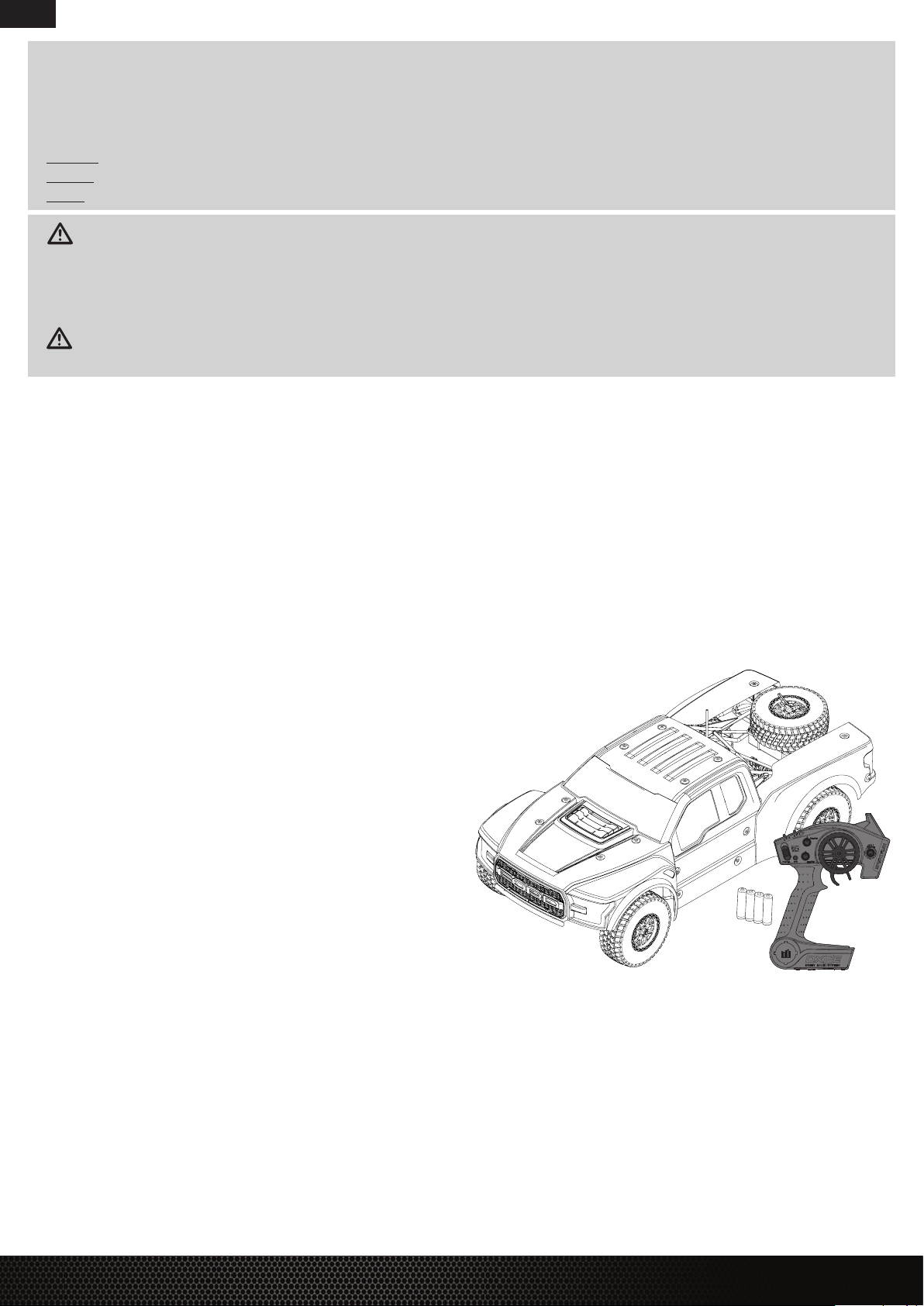
COMPONENTS
• Losi® Ford Raptor Baja Rey® RTR with AVC® technology: 1/10-Scale 4WD Desert Truck
• Spektrum™ DX2E 2.4GHz Transmitter (SPM2335)
• Spektrum™ 6-Channel DSMR® AVC Surface Receiver (SPMSRS6000)
• Spektrum™ 9KG 23T Waterproof Servo (SPMS605)
• Dynamite® Fuze™ 130A Sensorless Brushless Waterproof ESC (DYN4955)
• Dynamite® Fuze™ 550 Brushless Motor 3800Kv (DYNS1616)
• 4 AA batteries (for transmitter)
2
2
FORD® RAPTOR BAJA REY®: 1:10 4WD RTR • INSTRUCTION MANUAL
FORD® RAPTOR BAJA REY®: 1:10 4WD RTR • INSTRUCTION MANUAL
Page 3

WATER-RESISTANT VEHICLE WITH WATERPROOF ELECTRONICS
Your new Horizon Hobby vehicle has been designed and built with a combination of
waterproof and water-resistant components to allow you to operate the product in many
“wet conditions,” including puddles, creeks, wet grass, snow and even rain.
While the entire vehicle is highly water-resistant, it is not completely waterproof and your
vehicle should NOT be treated like a submarine. The various electronic components used in the
vehicle, such as the Electronic Speed Control (ESC), servo(s) and receiver are waterproof, however, most of the mechanical components are water-resistant and should not be submerged.
Metal parts, including the bearings, hinge pins, screws and nuts, as well as the contacts
in the electrical cables, will be susceptible to corrosion if additional maintenance is not
performed after running in wet conditions. To maximize the long-term performance of your
vehicle and to keep the warranty intact, the procedures described in the “Wet Conditions
Maintenance” section below must be performed regularly if you choose to run in wet
conditions. If you are not willing to perform the additional care and maintenance
required, then you should not operate the vehicle in those conditions.
CAUTION: Failure to exercise caution while using this product and
complying with the following precautions could result in product malfunction
and/or void the warranty.
• Driving in wet conditions can reduce the life of the motor. The additional resistance of
operating in water causes excess strain. Alter the gear ratio by using a smaller pinion or
larger spur gear. This will increase torque (and motor life) when running in mud, deeper
puddles, or any wet conditions that will increase the load on the motor for an extended
period of time.
WET CONDITIONS MAINTENANCE
• Drain any water that has collected in the tires by spinning them at high speed. With the
body removed, place the vehicle upside down and pull full throttle for a few short bursts
until the water has been removed.
CAUTION: Always keep hands, fingers, tools and any loose or hanging objects
away from rotating parts when performing the above drying technique.
• Remove the battery pack(s) and dry the contacts. If you have an air compressor or a can
of compressed air, blow out any water that may be inside the recessed connector housing.
• Remove the tires/wheels from the vehicle and gently rinse the mud and dirt off with a
garden hose. Avoid rinsing the bearings and transmission.
EN
EN
GENERAL PRECAUTIONS
• Read through the wet conditions maintenance procedures and make sure that you
have all the tools you will need to properly maintain your vehicle.
• Not all batteries can be used in wet conditions. Consult the battery manufacturer before
use. Caution should be taken when using Li-Po batteries in wet conditions.
• Most transmitters are not water-resistant. Consult your transmitter’s manual or the
manufacturer before operation.
• Never operate your transmitter or vehicle where lightning may be present.
• Do not operate your vehicle where it could come in contact with salt water (ocean
water or water on salt-covered roads), contaminated or polluted water. Salt water
is very conductive and highly corrosive, so use caution.
• Even minimal water contact can reduce the life of your motor if it has not been certified
as water-resistant or waterproof. If the motor becomes excessively wet, apply very light
throttle until the water is mostly removed from the motor. Running a wet motor at high
speeds may rapidly damage the motor.
NOTICE: Never use a pressure washer to clean your vehicle.
• Use an air compressor or a can of compressed air to dry the vehicle and help remove
any water that may have gotten into small crevices or corners.
• Spray the bearings, drive train, fasteners and other metal parts with a water-displacing
light oil. Do not spray the motor.
• Let the vehicle air dry before you store it. Water (and oil) may continue
to drip for a few hours.
• Increase the frequency of disassembly, inspection and lubrication of the following:
- Front and rear axle hub assembly bearings.
- All transmission cases, gears and differentials.
- Motor—clean with an aerosol motor cleaner and re-oil the bushings
with lightweight motor oil.
QUICK START
Please read the entire manual to gain a full understanding of the Baja Rey vehicle, fine-tuning the setup and performing maintenance.
1. Read the safety precautions found in this manual.
2. Charge a battery for the vehicle. Refer to the included charging warnings
and instructions for battery charging information.
3. Install the AA batteries in the transmitter. Only use alkaline
or rechargeable batteries.
4. Install the fully charged battery in the vehicle.
5. Power ON the transmitter and then the vehicle. Wait 5 seconds for the ESC to
initialize. Always power the transmitter ON before the vehicle and power it OFF
after the vehicle has been powered OFF.
6. Check the steering and throttle control directions. Verify that the servos
are moving in the correct direction.
7. Drive your vehicle.
8. Perform any necessary maintenance.
CHARGING THE BATTERY
Choose a battery designed to work with the Dynamite® Fuze™ 130A Sensorless BL
Waterproof ESC. We recommend the Dynamite® 7.4 5000mAh 2S 30C LiPo: Hardcase
with EC3™ connector (DYN9005EC). Choose a charger designed to charge 2S Li-Po
FORD® RAPTOR BAJA REY®: 1:10 4WD RTR • INSTRUCTION MANUAL
FORD® RAPTOR BAJA REY®: 1:10 4WD RTR • INSTRUCTION MANUAL
batteries. We recommend the Dynamite® Prophet™ Sport Li-Po 35W AC Battery Charger
(DYNC2005CA). Refer to your battery and charger manuals for usage, safety, and charging
information.
3
3
Page 4
EN
EN
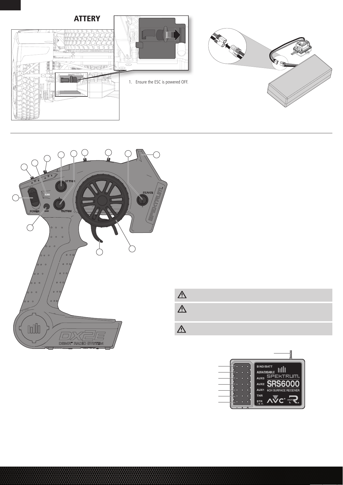
INSTALLING THE BATTERY
SPEKTRUM™ DX2E RADIO SYSTEM
10 11
9 12
8
7
6
5
4
3
1. Ensure the ESC is powered OFF.
2. Slide the button to the right to release the battery door.
3. Install the fully charged battery in the vehicle.
4. Connect the battery to the ESC.
5. Close the battery door and slide the battery door button to the left to secure it.
6. Power ON the transmitter, then the vehicle.
13
1. Steering Wheel Controls direction (left/right) of the model
2. Throttle Trigger Controls speed and direction (forward/brake/reverse) of the model
3. BIND Button Puts the transmitter into Bind Mode
4. ON/OFF Switch Turns the power ON/OFF for the transmitter
5. TH.REV Reverses function of the speed control when pulled back or pushed forward
6. Indicator Lights
- Solid green light—indicates adequate battery power
- Flashing green light—indicates the battery voltage is critically low. Replace batteries
7. ST. REV Reverses the function of the steering when the wheels is turned left or right
8. ST Trim Adjusts the steering center point
9. TH Trim Adjusts the throttle neutral point
10. TH Limiter Limits throttle output to 50, 70 or 100%.
11. 3-Position Switch Used to control a third channel and is preset at -100%/Neutral/100%
12. ST Rate Adjusts the sensitivity of AVC technology
13. Antenna Transmits the signal to the model
2
1
INSTALLING THE TRANSMITTER BATTERIES
1. Push in the battery cover a small amount to release the retaining tab, then remove the cover.
2. Install 4 AA batteries, taking care to align the battery polarity to the diagram in the
transmitter’s battery case.
3. Carefully reinstall the battery cover by aligning the tabs with the slots on the transmitter.
For more information on the transmitter, go to www.horizonhobby.com and click
on the support tab for the Spektrum DX2E to download the instruction manual.
CAUTION: Never remove the transmitter batteries while the model is powered ON.
Loss of model control, damage, or injury may occur.
CAUTION: If using rechargeable batteries, charge only rechargeable batteries.
Charging non-rechargeable batteries may cause the batteries to burst, resulting in
injury to persons and/or damage to property.
CAUTION: Risk of explosion if battery is replaced by an incorrect type. Dispose of
used batteries according to national regulations.
SRS6000 AVC TECHNOLOGY RECEIVER
Antenna
Bind/Battery
Aux 4/Disable
Aux 3
Aux 2
Aux 1
Throttle
Steering
AUX CHANNELS
The Aux channels can operate as additional servo channels, or as a power supply for a
personal transponder.
If AVC is active, only 4 channels; Steering, Throttle, AUX3 and AUX4 are operational.
The remaining Aux channels can be used to power a personal transponder or lights.
If AVC is disabled (see DISABLING THE STABILITY ASSIST FUNCTION), all 6 channels
including the Aux channels can operate as servo channels.
FORD® RAPTOR BAJA REY®: 1:10 4WD RTR • INSTRUCTION MANUAL
4
4
FORD® RAPTOR BAJA REY®: 1:10 4WD RTR • INSTRUCTION MANUAL
Page 5
EN
EN
STABILITY ASSIST RECEIVER
AVC® – ACTIVE VEHICLE CONTROL™
The Spektrum receiver features Active Vehicle Control™ (AVC®) technology that responds
similar to traction control in full-scale vehicles. In addition to traction control, AVC technology
also increases steering stability during high speed driving or while driving over rough terrain.
As you increase the AVC sensitivity, the system increases steering stability and traction control,
similar to reducing the amount of steering rate in a computer transmitter. Reducing the sensitivity value increases the amount of steering control from the transmitter. The receiver also
enables you to quickly turn AVC on or off if you participate in organized racing.
IMPORTANT: You must use digital servos with the AVC receiver. Do not use analog servos as
they willl reduce the performance of the system and may cause overheating.
CALIBRATING THE RECEIVER
1. With the vehicle on a flat, level surface, insert the Bind Plug in the BIND port on the
receiver.
2. Connect a fully charged battery pack to the ESC.
3. Power on the ESC. The orange LED flashes, indicating the receiver is in bind mode.
4. Center the ST TRIM and TH TRIM dials on the transmitter.
5. Press and hold the BIND button while powering on the transmitter.
6. Release the BIND button when the orange LED slowly flashes. The transmitter and receiver
are linked when the orange LED is solid.
7. Pull the transmitter trigger to Full Throttle.
8. Push the transmitter trigger to Full Brake, then return the trigger to center.
9. Turn the transmitter steering wheel to Full Right.
10. Turn the transmitter steering wheel to Full Left, then return the steering wheel to center.
The orange LED flashes once.
11. Remove the Bind Plug, then power off the receiver to save the settings.
12. Power off the transmitter.
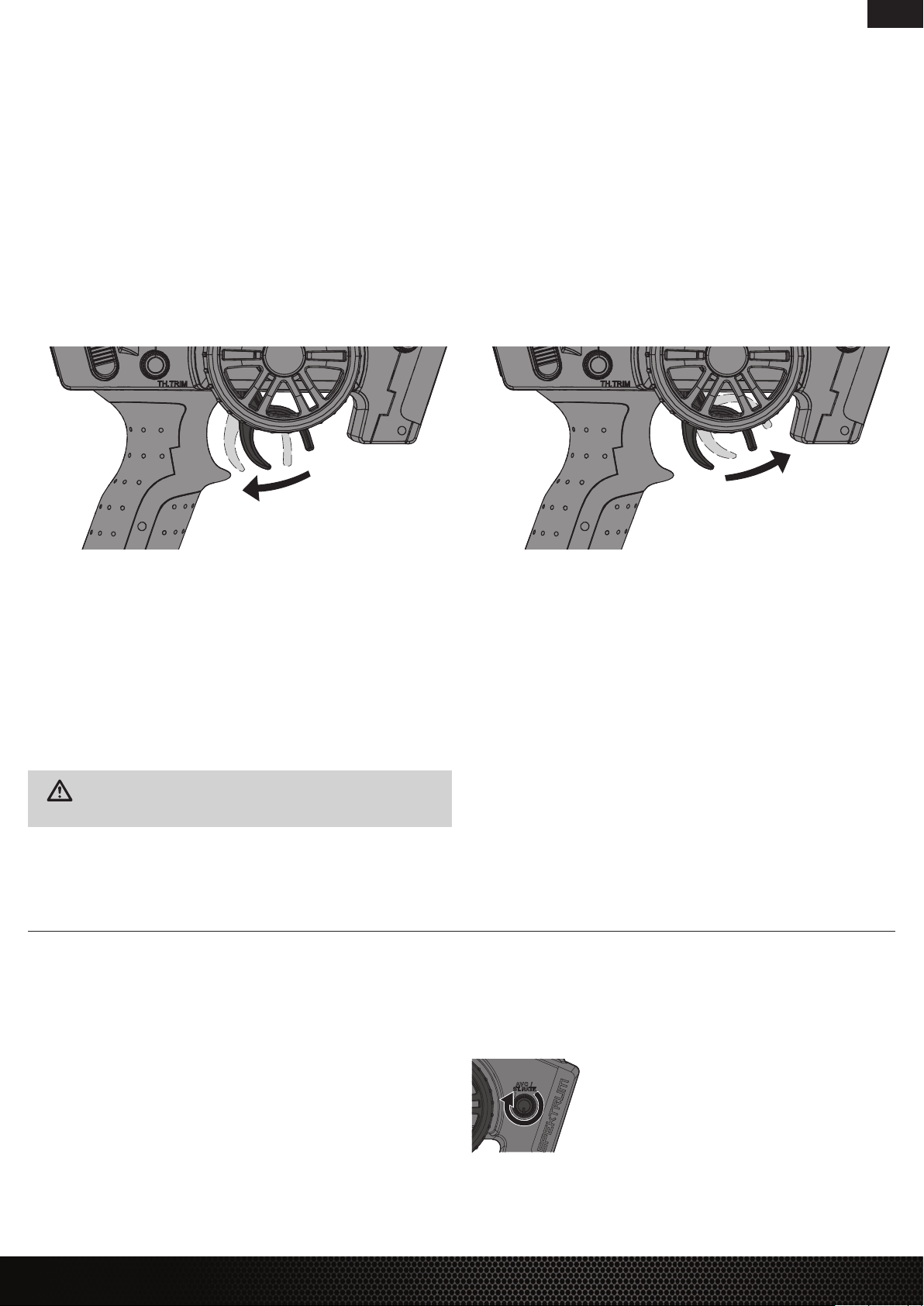
FORWARD BRAKE/REVERSE
DRIVING PRECAUTIONS
• Maintain sight of the vehicle at all times.
• Routinely inspect the vehicle for loose wheel hardware.
• Routinely inspect the steering assembly for any loose hardware. Driving the vehicle
off-road can cause fasteners to loosen over time.
• Do not drive the vehicle in tall grass. Doing so can damage the vehicle or electronics.
• Stop driving the vehicle when you notice a lack of power. Driving the vehicle when
the battery is discharged can cause the receiver to power off. If the receiver loses power,
you will lose control of the vehicle. Damage due to an over-discharged Li-Po battery is
not covered under warranty.
CAUTION: Do not discharge a Li-Po battery below 3V per cell. Batteries discharged to a voltage lower than the lowest approved voltage may become dam-
aged, resulting in loss of performance and potential fire when batteries are charged.
• Do not apply forward or reverse throttle if the vehicle is stuck.
Applying throttle in this instance can damage the motor or ESC.
• After driving the vehicle, allow the electronics to cool before driving the vehicle again.
IMPORTANT: Keep wires away from all moving parts.
BEFORE RUNNING YOUR VEHICLE
1. Check for free suspension movement. All suspension arms and steering components
should move freely. Any binds will cause the vehicle to handle poorly.
2. Charge a battery pack. Always charge the battery pack as per the battery and/or
charger manufacturers’ instructions.
3. Set the transmitter steering trim. Follow the instructions to set the steering trim/subtrim
so that the vehicle drives straight with no input to the steering.
4. Perform a Control Direction Test.
POWERING ON THE VEHICLE
1. Center the ST TRIM and TH TRIM dials on the transmitter.
2. Power on the transmitter.
3. Remove the body from the vehicle.
4. Connect a fully charged battery pack to the ESC.
5. Power on the ESC.
IMPORTANT: The vehicle MUST remain on a flat, level surface and motionless for at least 5
seconds.
AVC® SENSITIVITY
The ST RATE dial adjusts the sensitivity, or stability, value in the receiver. If you increase the
sensitivity, the AVC® system becomes more sensitive to the vehicle drifting left or right. You
would use maximum sensitivity during high speed driving or drag racing, when you want
the vehicle to stay in a straight line. As the sensitivity value increases, the amount of
steering travel decreases.
Turn the ST RATE knob counter-clockwise to reduce the sensitivity.
Turn the ST RATE knob clockwise to increase the sensitivity.
IMPORTANT: The ST RATE knob will only adjust the sensitivity when
the transmitter is bound to a DSMR® receiver. When the transmitter
is bound to a DSM®, DSM2® or DSM Marine receiver,
the ST RATE knob controls the steering dual rate.
FORD® RAPTOR BAJA REY®: 1:10 4WD RTR • INSTRUCTION MANUAL
FORD® RAPTOR BAJA REY®: 1:10 4WD RTR • INSTRUCTION MANUAL
5
5
Page 6
EN
EN
EN
DISABLING AVC® TECHNOLOGY
If you participate in organized racing, you may be required to turn AVC off. To turn AVC off:
1. Insert a Bind Plug in the BIND port on the receiver.
2. Insert a second Bing Plug in the DISABLE port on the receiver.
3. Connect a fully charged battery pack to the ESC.
4. Power on the ESC. The orange LED flashes, indicating the receiver is in bind mode.
5. Center the ST TRIM and TH TRIM dials on the transmitter.
6. Press and hold the BIND button while powering on the transmitter.
7. Release the BIND button when the orange LED slowly flashes. The transmitter and receiver
are linked when the orange LED is solid.
8. Pull the transmitter trigger to Full Throttle.
9. Push the transmitter trigger to Full Brake, then return the trigger to center.
10. Turn the transmitter steering wheel to Full Right.
11. Turn the transmitter steering wheel to Full Left, then return the steering wheel to center.
The orange LED flashes once.
12. Remove the Bind Plugs, then power off the receiver to save the settings. The receiver will
continuously blink to indicate AVC is disabled.
13. Power off the transmitter.
IMPORTANT: You must calibrate the receiver each time it is placed in bind mode. To activate
AVC, see the steps in “Calibrating the Receiver.”
RUN TIME
The largest factor in run time is the capacity of the battery pack. A larger mAh rating
increases the amount of run time experienced.
The condition of a battery pack is also an important factor in both run time and speed.
The battery connectors may become hot during driving. Batteries will lose performance
and capacity over time.
Driving the vehicle from a stop to full speed repeatedly will damage the batteries
and electronics over time. Sudden acceleration will also lead to shorter run times.
TO IMPROVE RUN TIMES
• Keep your vehicle clean and well maintained.
• Allow more airflow to the ESC and motor.
• Change the gearing to a lower ratio. A lower ratio decreases the operating temperature
of the electronics. Use a smaller pinion gear or larger spur gear to lower the gear ratio.
• Use a battery pack with a higher mAh rating.
• Use the optimum charger to charge battery packs. (Visit your local hobby dealer for
more information.)
PERFORMING A CONTROL DIRECTION TEST
Perform a control test with the vehicle wheels off the ground. If the wheels rotate after the
vehicle is powered ON, adjust the TH TRIM knob until they stop. To make the wheels move
forward, pull the trigger. To reverse them, wait for the wheels to stop, then push the trigger.
When moving forward, the wheels should maintain a straight line without any steering wheel
input. If not, adjust the ST TRIM knob, so the wheels maintain a straight line without having
to turn the steering wheel.
CHANGING THE TRAVEL ADJUST SETTINGS
1. Hold the trigger in the full brake position and turn the steering wheel to Full Right while
powering on the transmitter. The LED flashes rapidly, indicating the programming mode is
active.
2. Throttle End Point: Continue holding full throttle. Turn the TH TRIM knob to adjust
the full throttle end point.
3. Brake End Point: Hold the trigger in the full brake position. Turn the TH TRIM knob
to adjust the full brake end point. Return the trigger to the center position.
4. Left Steering End Point: Hold the steering wheel in the full left position. Turn
the ST TRIM knob to adjust the left end point.
5. Right Steering End Point: Hold the steering wheel in the full right position. Turn the ST
TRIM knob to adjust the right end point. Return the steering wheel to the center position.
6. Power off the transmitter to save the travel adjust settings.
The minimum travel is 75%, and the maximum travel is 150%.
IMPORTANT: If the travel is changed on the DX2E, you must rebind and calibrate
the receiver.
DYNAMITE® FUZE™ 130A SENSORLESS BRUSHLESS ESC
SPECIFICATIONS
Type Sensorless
Constant/Peak 130A/760A
Resistance 0.0004 Ohm
Function Forward/Brake–Forward/Brake Reverse
Operation Proportional forward, proportional reverse with braking delay
Input Voltage 7.4V–14.8V (The motor in this vehicle will not support 14.8V.)
BEC Output 6V/3A
Overload Protection Thermal
Dimensions (LxWxH) 53.5mm x 36mm x 36mm
Weight 79 g
ESC LED STATUS
• No ESC LEDs will glow when there is no throttle input from the transmitter.
• The red ESC LED glows when there is any throttle input from the transmitter.
AUDIBLE WARNING TONES
1. Input Voltage: The ESC checks the in put voltage when it is powered ON. If a voltage
problem is detected, the ESC continuously sounds 2 beeps with a 1 second pause
(xx-xx-xx). Power OFF the ESC and ensure the connections are secure and that
the battery power is not too low for safe operation.
2. Radio Connection: The ESC checks radio signal input when it is powered ON.
If a problem is detected, the ESC continuously sounds 1 beep with a 2 second pause
(x--x--x). Power OFF the ESC and ensure the radio system is operating correctly.
6
6
For sensorless brushless motors:
1. Connect the ESC terminal A (typically designated by a blue wire) to the motor’s terminal
A (red wire on a Dynamite® Fuze™ sensorless motor). This may also be changed in
Programming Item 12, Motor Rotation, without changing wire connections.
2. Connect the ESC terminal B (typically designated by a yellow wire) to the motor’s terminal
B (blue wire on a Dynamite® Fuze™ sensorless motor).
3. Connect the ESC terminal C (typically designated by an orange wire) to the motor’s
terminal C (black wire on a Dynamite® Fuze™ sensorless motor).
NOTICE: Always disconnect the battery from the ESC when you have finished operating
your vehicle. The ESC’s switch only controls power to the receiver and servos. The ESC
will continue to draw current when connected to the battery, resulting in possible damage to the battery through over discharge.
ESC CALIBRATION PROCEDURE
Ensure proper ESC function by calibrating the ESC to your transmitter inputs.
1. Power OFF the ESC.
2. Ensure your transmitter is powered ON, the throttle is not reversed, the throttle trim is
neutral and the throttle travel range is at 100%. Disable any special functions such as
ABS, etc.
3. Press the SET button while powering ON the ESC. Release the button as soon as the red
LED starts to flash.
4. Calibrate the throttle points by pressing the SET button once after each step.
- Neutral (1 flash)—leave the throttle at rest, untouched
- Full throttle (2 flashes)—pull the throttle fully back
- Full brake/reverse (3 flashes)—push the throttle fully forward
5. The motor will run 3 seconds after the last step is completed.
Tip: If the motor turns in the wrong direction, reverse the connection of any 2 outside
motor wires. The center wire must remain in the center and cannot be moved to another
motor tab.
FORD® RAPTOR BAJA REY®: 1:10 4WD RTR • INSTRUCTION MANUAL
TEN-SCBE RTR, AVC: 1:10 4WD SCBE • INSTRUCTION MANUAL
FORD® RAPTOR BAJA REY®: 1:10 4WD RTR • INSTRUCTION MANUAL
Page 7

EN
EN
ESC FUNCTIONS AND MODES
The ESC includes programming options so you can adjust the way your vehicle performs.
Refer to the included settings table to adjust the ESC for your driving conditions.
ESC PROGRAMMING PROCEDURE
Programming is accomplished using the SET button on the ON/OFF switch or Digital Program
Box (DYNS3005).
1. Connect a fully charged battery to the ESC.
2. Power ON the ESC using the ESC switch.
3. Hold the SET button for 1 second until the green LED blinks, then release the SET button
to enter programming mode.
PROGRAMMABLE ITEMS
Basic Items
1 Running Mode Forward w/ brake Forward/Reverse w/ brake Forward/Reverse
2 Drag Brake Force 0% 5% 10% 20% 40% 60% 80% 100%
3 Low Voltage Cutoff non-protection 2.6V/Cell 2.8V/Cell 3.0V/Cell 3.2V/Cell 3.4V/Cell
4 Start Mode Level 1 Level 2 Level 3 Level 4 Level 5 Level 6 Level 7 Level 8 Level 9
PROGRAMMABLE ITEMS
Advanced Items
5 Max Brake Force 25% 50% 75% 100% disable
6 Max Reverse Force 25% 50% 75% 100%
7 Initial Brake Force = Drag Brake Force 0% 20% 40%
8 Neutral Range 6% (Narrow) 9% (Normal) 12% (Wide)
9 Timing 0.00º 3.75º 7.50º 11.25º 15.00º 18.75º 22.50º 26.25º
10 Reserved Item
11 Reserved Item
12 Motor Rotation Counterclockwise Clockwise
13 Li-Po Cells Auto Calculate 2 Cells 3 Cells 4 Cells 5 Cells 6 Cells
PROGRAMMABLE VALUE Default Settings
1 2 3 4 5 6 7 8 9
PROGRAMMABLE VALUE Default Settings
1 2 3 4 5 6 7 8 9
4. Press and release the SET button as needed to get to the desired menu option (the Green
LED will blink corresponding to the menu item number). Programming menu items 1
through 9 are accessible using the SET button on the ESC. Programming menu items 10 and
above are only accessible using the optional ESC programming card. Programming of menu
items 10 and 11 is only possible after firmware updates to the ESC programming card.
5. When at the desired menu item, hold the SET button for 3 seconds until the red LED blinks.
6. Press the SET button to move among the settings based on how many times the red LED
blinks (Refer to the table for more information).
7. Save the setting by holding the SET button for 3 seconds.
8. Power OFF the ESC switch and repeat the instructions above to change other settings.
Tip: If desired, the ESC programming can be returned to default settings
by powering ON the ESC and holding the SET button for 5 seconds.
DESCRIPTIONS
1. Running Mode
- Forward Only with Brake
Intended for competition use, this mode allows only forward and brake controls.
- Forward/Reverse with Brake
This mode is the basic all-around mode, allowing forward, reverse and brake controls.
To engage reverse while moving forward, apply the brake until the vehicle has come to
a complete stop, release brake, then apply the brake again. While braking or in reverse,
engaging the throttle will result in the vehicle immediately accelerating forward.
2. Drag Brake Force
Adjusts the amount of brake automatically applied when the throttle is returned to the
neutral position. This simulates the engine braking effect of a full-scale vehicle, allowing
improved turn-in and your vehicle’s general response to controls.
3. Low Voltage Cutoff
This function helps to prevent battery over-discharge. The ESC continuously monitors the
battery’s voltage. If the voltage falls below the voltage threshold for 2 seconds, the output
power shuts off and the red LED flashes twice repeatedly.
The cutoff threshold calculation is based on individual Li-Po cell voltage. For Ni-MH batteries,
if the voltage battery pack is higher than 9.0V, it will be treated as a 3-cell Li-Po battery
pack; if it is lower than 9.0V, it will be treated as a 2-cell Li-Po battery pack. Example: for a
8.0V Ni-MH battery pack used with a 2.6V/cell threshold, it will be treated as a 2-cell Li-Po
battery pack and the low-voltage cut-off threshold will be 5.2V (2.6x2=5.2).
4. Start Mode (Punch)
Sets the initial throttle punch when the car accelerates. Level 1 gives
a very soft initial acceleration and level 4 gives a stronger initial acceleration.
5. Max Brake Force
Adjusts the maximum braking force. A higher value provides stronger braking,
but can also cause the wheels to lock, resulting in loss of control of the car.
6. Max Reverse Force
This parameter adjusts the maximum power when travelling in reverse.
7. Initial Brake Force (minimum brake)
Adjusts the minimum amount of braking power when the brakes engage. The default
value is equal to the drag brake value. A high value can lock the wheels when the brake
is used.
8. Neutral Range
Adjusts the throttle sensitivity around the neutral point. A higher value results in the
throttle having to be moved more for the vehicle to move forward, backward or brake.
9. Timing
Adjusts the motor drive current timing. More timing gives more performance, but can
lower efficiency and cause damage to the motor and/or ESC by overload or overheating.
NOTICE: Always ensure the motor timing is set correctly. Failure to set the motor
timing correctly can result in damage to the motor and ESC. Refer to the manufacturer
instructions for recommended timing settings.
The Following Programmable Items require the optional Digital ESC Program Box:
10. and 11. Available Items are subject to firmware updates to the ESC and the optional
digital program box.
12. Motor Rotation
Allows you to make this change in the ESC so no wires need to be changed between the
ESC and the motor.
13. Li-Po Cells
Allows the ESC to automatically detect or manually set the number of cells in your Li-Po
battery back.
FORD® RAPTOR BAJA REY®: 1:10 4WD RTR • INSTRUCTION MANUAL
FORD® RAPTOR BAJA REY®: 1:10 4WD RTR • INSTRUCTION MANUAL
7
7
Page 8

EN
EN
EN
DYNAMITE® FUZE™ 3800KV BRUSHLESS MOTOR
PRECAUTIONS
• Never touch moving parts.
• Never disassemble while the batteries are installed.
• Always let parts cool before touching.
GEARING
Your vehicle has been equipped with the optimal gearing for the stock platform. It offers an
ideal balance between speed, power and efficiency. Should you decide to customize your
vehicle with optional batteries or motors, it may be necessary for you to change the pinion or
spur gear.
Installing a pinion gear with fewer teeth or a spur gear with more teeth will provide greater
torque but will reduce top speed. Likewise, a pinion gear with more teeth or a spur gear with
fewer teeth will reduce torque and increase top speed. Care should be taken when installing
larger pinion gears as this can “overgear” the vehicle, resulting in overheating of the motor
and ESC. When testing different gearing options, pay close attention to the temperature of
the motor and speed control to ensure you are operating within the temperature range of the
components. The motor or ESC should never be so hot that it cannot be touched. If temperatures are too hot, a different gearing combination with a lower pinion gear and/or higher spur
gear is suggested.
TROUBLESHOOTING GUIDE
PROBLEM POSSIBLE CAUSE SOLUTION
Battery not charged or plugged in Charge battery/plug in
Vehicle does not operate
Motor runs but wheels
do not rotate
Steering does not work
Will not turn one direction Servo gears damaged Replace or repair servo
Motor does not run
ESC gets hot
Poor run time and/or sluggish
acceleration
Poor range and/or glitching
ESC switch not “On” Turn on ESC switch
Transmitter not “On” or low battery Turn on/replace batteries
Pinion not meshing with spur gear Adjust pinion/spur mesh
Pinion spinning on motor shaft Tighten pinion gear setscrew on motor shaft flat spot
Transmission gears stripped Replace transmission gears
Drive pin broken Check and replace drive pin
Servo plug not in receiver properly Make sure the steering servo plug is connected to the receiver steering channel, noting proper polarity
Servo gears or motor damaged Replace or repair servo
Motor wire solder joint is damaged Resolder the motor wire with the proper equipment
Motor wire broken Repair or replace as needed
ESC damaged Contact Horizon Hobby Product Support
Motor over-geared Use smaller pinion or larger spur gear
Driveline bound up Check wheels and transmission for binding
Battery pack not fully charged Recharge battery
Charger not allowing full charge Try another charger
Driveline bound up Check wheels, transmission for binding
Transmitter batteries low Check and replace
Vehicle battery low Recharge battery
Loose plugs or wires Check all wire connections and plugs
8
8
FORD® RAPTOR BAJA REY®: 1:10 4WD RTR • INSTRUCTION MANUAL
FORD® RAPTOR BAJA REY®: 1:10 4WD RTR • INSTRUCTION MANUAL
Page 9

EN
EN
2-YEAR LIMITED WARRANTY
What this Warranty Covers
Horizon Hobby, LLC, (Horizon) warrants to the original purchaser that the product purchased
(the “Product”) will be free from defects in materials and workmanship for a period of 2 years
from the date of purchase.
What is Not Covered
This warranty is not transferable and does not cover (i) cosmetic damage, (ii) damage due
to acts of God, accident, misuse, abuse, negligence, commercial use, or due to improper use,
installation, operation or maintenance, (iii) modification of or to any part of the Product, (iv)
attempted service by anyone other than a Horizon Hobby authorized service center, (v) Product
not purchased from an authorized Horizon dealer, or (vi) Product not compliant with applicable
technical regulations or (vii) use that violates any applicable laws, rules, or regulations.
OTHER THAN THE EXPRESS WARRANTY ABOVE, HORIZON MAKES NO OTHER WARRANTY
OR REPRESENTATION, AND HEREBY DISCLAIMS ANY AND ALL IMPLIED WARRANTIES,
INCLUDING, WITHOUT LIMITATION, THE IMPLIED WARRANTIES OF NON-INFRINGEMENT,
MERCHANTABILITY AND FITNESS FOR A PARTICULAR PURPOSE. THE PURCHASER
ACKNOWLEDGES THAT THEY ALONE HAVE DETERMINED THAT THE PRODUCT WILL SUITABLY
MEET THE REQUIREMENTS OF THE PURCHASER’S INTENDED USE.
Purchaser’s Remedy
Horizon’s sole obligation and purchaser’s sole and exclusive remedy shall be that Horizon
will, at its option, either (i) service, or (ii) replace, any Product determined by Horizon to be
defective. Horizon reserves the right to inspect any and all Product(s) involved in a warranty
claim. Service or replacement decisions are at the sole discretion of Horizon. Proof of purchase
is required for all warranty claims. SERVICE OR REPLACEMENT AS PROVIDED UNDER THIS
WARRANTY IS THE PURCHASER’S SOLE AND EXCLUSIVE REMEDY.
Limitation of Liability
HORIZON SHALL NOT BE LIABLE FOR SPECIAL, INDIRECT, INCIDENTAL OR CONSEQUENTIAL
DAMAGES, LOSS OF PROFITS OR PRODUCTION OR COMMERCIAL LOSS IN ANY WAY,
REGARDLESS OF WHETHER SUCH CLAIM IS BASED IN CONTRACT, WARRANTY, TORT,
NEGLIGENCE, STRICT LIABILITY OR ANY OTHER THEORY OF LIABILITY, EVEN IF HORIZON HAS
BEEN ADVISED OF THE POSSIBILITY OF SUCH DAMAGES. Further, in no event shall the liability
of Horizon exceed the individual price of the Product on which liability is asserted. As Horizon
has no control over use, setup, final assembly, modification or misuse, no liability shall be
assumed nor accepted for any resulting damage or injury. By the act of use, setup or assembly,
the user accepts all resulting liability. If you as the purchaser or user are not prepared to
accept the liability associated with the use of the Product, purchaser is advised to return the
Product immediately in new and unused condition to the place of purchase.
Law
These terms are governed by Illinois law (without regard to conflict of law principals). This
warranty gives you specific legal rights, and you may also have other rights which vary from
state to state. Horizon reserves the right to change or modify this warranty at any time without
notice.
WARRANTY SERVICES
Questions, Assistance, and Services
Your local hobby store and/or place of purchase cannot provide warranty support or service.
Once assembly, setup or use of the Product has been started, you must contact your local
distributor or Horizon directly. This will enable Horizon to better answer your questions and
service you in the event that you may need any assistance. For questions or assistance, please
visit our website at www.horizonhobby.com, submit a Product Support Inquiry, or call the toll
free telephone number referenced in the Warranty and Service Contact Information section to
speak with a Product Support representative.
Inspection or Services
If this Product needs to be inspected or serviced and is compliant in the country you live
and use the Product in, please use the Horizon Online Service Request submission process
found on our website or call Horizon to obtain a Return Merchandise Authorization (RMA)
number. Pack the Product securely using a shipping carton. Please note that original boxes
may be included, but are not designed to withstand the rigors of shipping without additional
protection. Ship via a carrier that provides tracking and insurance for lost or damaged parcels,
as Horizon is not responsible for merchandise until it arrives and is accepted at our facility.
An Online Service Request is available at http://www.horizonhobby.com/content/_servicecenter_render-service-center. If you do not have internet access, please contact Horizon
Product Support to obtain a RMA number along with instructions for submitting your product
for service. When calling Horizon, you will be asked to provide your complete name, street
address, email address and phone number where you can be reached during business hours.
When sending product into Horizon, please include your RMA number, a list of the included
items, and a brief summary of the problem. A copy of your original sales receipt must be
included for warranty consideration. Be sure your name, address, and RMA number are clearly
written on the outside of the shipping carton.
NOTICE: Do not ship Li-Po batteries to Horizon. If you have any issue with a
Li-Po battery, please contact the appropriate Horizon Product Support office.
Warranty Requirements
For Warranty consideration, you must include your original sales receipt verifying
the proof-of-purchase date. Provided warranty conditions have been met, your Product
will be serviced or replaced free of charge. Service or replacement decisions are at the sole
discretion of Horizon.
Non-Warranty Service
Should your service not be covered by warranty, service will be completed and
payment will be required without notification or estimate of the expense unless
the expense exceeds 50% of the retail purchase cost. By submitting the item for
service you are agreeing to payment of the service without notification. Service estimates are
available upon request. You must include this request with your item submitted for service.
Non-warranty service estimates will be billed a minimum of ½ hour of labor. In addition you
will be billed for return freight. Horizon accepts money orders and cashier’s checks, as well as
Visa, MasterCard, American Express, and Discover cards. By submitting any item to Horizon for
service, you are agreeing to Horizon’s Terms and Conditions found on our website http://www.
horizonhobby.com/content/service-center_render-service-center.
ATTENTION: Horizon service is limited to Product compliant in the country of
use and ownership. If received, a non-compliant Product will not be serviced.
Further, the sender will be responsible for arranging return shipment of
the un-serviced Product, through a carrier of the sender’s choice and at the
sender’s expense. Horizon will hold non-compliant Product for a period of 60
days from notification, after which it will be discarded.
10/15
FORD® RAPTOR BAJA REY®: 1:10 4WD RTR • INSTRUCTION MANUAL
FORD® RAPTOR BAJA REY®: 1:10 4WD RTR • INSTRUCTION MANUAL
9
9
Page 10

EN
EN
EN
Warranty and Service Contact Information
Country of Purchase Horizon Hobby Contact Information Address
Horizon Service Center
(Repairs and Repair Requests)
United States of America
European Union
*For the most up-to-date customer service contact information, please visit: www.horizonhobby.com/content/service-center-render-service-center
Horizon Product Support
(Product Technical Assistance)
Sales
Horizon Technischer Service
Sales: Horizon Hobby GmbH
servicecenter.horizonhobby.com/RequestForm/
productsupport@horizonhobby.com
877-504-0233
websales@horizonhobby.com
800-338-4639
service@horizonhobby.eu
+49 (0) 4121 2655 100
Champaign, Illinois 61822 USA*
D 22885 Barsbüttel, Germany
2904 Research Road
Hanskampring 9
FCC STATEMENT
FCC ID: BRWDX2EQ2UC
FCC ID: BRWDASRX12
This equipment has been tested and found to comply with the limits for Part 15 of the FCC
rules. These limits are designed to provide reasonable protection against harmful interference
in a residential installation. This equipment generates uses and can radiate radio frequency
energy and, if not installed and used in accordance with the instructions, may cause harmful
interference to radio communications.
However, there is no guarantee that interference will not occur in a particular installation. If
this equipment does cause harmful interference to radio or television reception, which can be
determined by turning the equipment off and on, the user is encouraged to try to correct the
interference by one or more of the following measures:
• Reorient or relocate the receiving antenna.
• Increase the separation between the equipment and receiver.
• Connect the equipment to an outlet on a circuit different from that to which the receiver
is connected.
• Consult the dealer or an experienced radio/TV technician for help.
COMPLIANCE INFORMATION FOR THE EUROPEAN UNION
EU Compliance Statement: Horizon Hobby, LLC hereby declares that this
product is in compliance with the essential requirements and other relevant
provisions of the RED and EMC Directive.
A copy of the EU Declaration of Conformity is available online at:
http://www.horizonhobby.com/content/support-render-compliance.
This device complies with part 15 of the FCC rules. Operation is subject to the following
two conditions: (1) This device may not cause harmful interference, and (2) this device must
accept any interference received, including interference that may cause undesired operation.
NOTICE: Modifications to this product will void the user’s authority to operate this
equipment.
IC INFORMATION
IC: 6157A-DX2EQ2UC
IC: 6157A-AMRX12
This device complies with ISED Canada licence-exempt RSS standard(s). Operation is subject
to the following two conditions: (1) this device may not cause interference, and (2) this device
must accept any interference, including interference that may cause undesired operation of
the device.
Instructions for disposal of WEEE by users in the
European Union
This product must not be disposed of with other waste. Instead, it is the user’s
responsibility to dispose of their waste equipment by handing it over to a
designated collections point for the recycling of waste electrical and electronic
equipment. The separate collection and recycling of your waste equipment at the
time of disposal will help to conserve natural resources and ensure that it is recycled in a manner
that protects human health and the environment. For more information about where you can drop
off your waste equipment for recycling, please contact your local city office, your household waste
disposal service or where you purchased the product.
10
10
FORD® RAPTOR BAJA REY®: 1:10 4WD RTR • INSTRUCTION MANUAL
FORD® RAPTOR BAJA REY®: 1:10 4WD RTR • INSTRUCTION MANUAL
Page 11

Replacement Parts // Teileliste // Liste des pièces de rechange // Elenco dei ricambi
Part # English Deutsch Français Italiano
DYN4955 Fuze 130A Sensorless Brushless WP ESC
DYNS1616 Fuze 550BL Motor, 3800Kv Fuze 550BL Motor, 3800Kv Moteur Fuze Brushless 550, 3800Kv Motore brushless Fuze 550, 3800 Kv
LOSA3573 1.0 Module Pitch Pinion, 13T Ritzel Modul 1, 13T Pignon modulaire 1.0, 13 dents Pignone a passo modulare 1.0, 13 denti
LOSA6250 Set Screws, 4mm & 5mm (6) Madenschrauben 4 & 5 mm (je 6) Vis, 4mm et 5mm (6 chacun) Grani, 4 mm e 5 mm (6 cad.)
LOSA6937 5x10mm Sealed Ball Bearing (2) Kugelllager, gekapselt 5 x10mm Roulements à billes scellés 5x10mm (2) Cuscinetto a sfere sigillato 5x10 mm (2)
LOSA6940 6x12mm Sealed Ball Bearing (4) Kugelllager, gekapselt 6 x12mm (4) Roulements à billes scellés 6x12mm (4) Cuscinetto a sfere sigillato 6x12 mm (4)
LOSA6956 12x18x4mm Sealed Ball Bearing (2) Kugelllager gekapselt 12 x18x 4mm Roulements à billes scellés 12x18x4mm (2) Cuscinetto a sfere sigillato 12x18x4 mm (2)
LOSA6957 10x15x4mm Bearing Kugellager 5 x 10 x 4mm (2) Roulements 5 x 10 x 4mm (2) 10x15x4mm Cuscinetti 5 x 10 x 4mm (2)
LOSB3008 3x6x2.5mm Ball Bearing (2) Kugelllager, 3x6x2.5mm (2) Roulements à billes 3x6x2.5mm (2) Cuscinetto a sfere 3x6x2,5 mm (2)
LOS43025 Alpine Wheel and Tire Mounted (2) Montiertes Alpin-Rad und Reifen (2) Support volant et pneu alpin (2) Ruota alpina con pneumatico montato (2)
LOS230010 Roll Cage Sides L&R Überrollbügelteile links und rechts Faces latérales gauche et droite de l'arceau cage Parti laterali roll cage D&S
LOS230011 Top Bar, X-Bar,Cover & Tire Moun Obere Abdeckung, X-Abdeckung Barre supérieure, Barre X, protection et support pneu
LOS230012 Fr Bar, RR Body Mnt Bar, Bumper, Tower Support Karosserieteil hinten Stoßfänger
LOS230013 Body Button Base & Top (22) Body Button Base & Top (22) Anneaux de protection de carrosserie (22) Body Button Base & Top (22): Baja Rey
LOS230020 Interior Set with Helmets, Clear Interiorset mit Helmen, transparent Décoration intérieure avec casques, transparente Set interni con caschi, trasparente
LOS230066 King Shocks Raptor Body Set King Shocks Raptor-Karosseriesatz Ensemble de carrosserie King Shocks Raptor Set carrozzeria King Shocks Raptor
LOS230067 Black Rhino Raptor Body Set Black Rhino Raptor-Karosseriesatz Ensemble de carrosserie Black Rhino Raptor Set carrozzeria Black Rhino Raptor
LOS230068 Ford Raptor Body Adaptor Set Ford Raptor Body Karosserie-Adapterset Ensemble d’adaptateur de carrosserie Ford Raptor Set adattatore carrozzeria Ford Raptor
LOS230069 Rear Red LED Light Bar Rote LED-Leuchtbalken, hinten Barre d’éclairage à DEL arrière rouge Barra a LED rossa posteriore
LOS231005 Rear Bulkhead,Fan Panel, Mudguards Lüfterpanel, Schmutzfänger Cloison arrière, ventilateur et bavettes Paratia post., fan panel, parafango
LOS231006 Battery Tray,Door, Lock, 2S Spacer Akkuhalter und Klappe, 2S Distanzstück Support batterie, trappe, verrou et cales 2S
LOS231007 Front Upper Arm/Shock Mount, RR Chassis Brace Stoßdämpferbefestigung hinten mit Chassishalter
LOS231008 Servo Mount, Steering Servo Set Plastic Servohalter Support servo, servo de direction plastique
LOS231010 Chassis Plate & Motor Cover Plate Chassisplatte und Motorabdeckung Platine de châssis et couvercle moteur Piastra telaio & piastra copertura motore
LOS231011 Center Chassis Brace & Standoffs Chassishalter und Distanzstücke Renfort central de châssis et entretoises Montanti telaio centrali con distanziali
LOS231012 Motor Mount Motorhalter Support moteur Supporto motore
LOS231013 Steering Hardware Set Zubehörset Lenkung Set d'accessoires de direction Set hardware sterzo
LOS231058 Front Bumper Set Stoßstangensatz, Front Jeu de pare-chocs avant Set ammortizzatore anteriore
LOS232001 Axle Housing Set; Rear Achsgehäuseset hinten Carter de pont arrière Set alloggiamento asse posteriore
LOS232002 Center Transmission Housing Achsgehäuse mitte Boitier de transmission centrale Scatola trasmissione centrale
LOS232003 Front Gear Box/Bulkhead Getriebegehäuse mit Halter Set de carters de transmission avant/Cellule Scatola ingranaggio anteriore / paratia
LOS232004 HD Diff Housing & Internals: Baja Rey Differentialgehäuse mit Einsätzen Corps de différentiel renforcé et éléments internes Scatola diff. HD ed parti interne
LOS232005 Rear Driveshaft Set: Baja Rey Antriebswelle hinten Tiges de cardans arrière Set trasmissione posteriore
LOS232006 Hex, Rotor, Caliper & Pin Set (4) Scheibenbremse mit Bremssattel Vorne/Hinten Hexagone, rotor, mâchoires et goupilles Set esagone, rotore, spessore e perno
LOS232007 Center Transmission Gear Set Getriebeset Mitte Set de pignons de transmission centrale Set ingranaggio trasmissione centrale
LOS232008 40T Ring & 14T Pinion Gear FR/RR Stirnrad 40 Zähne & 14 er Ritzel Anneau 40T et Pignon 14T avant/arrière 40T ingranaggio & 14T pignone ant./post.
LOS232009 Front Axle Set (2) Vorderachsenset (2) Axe de roues avant (2) Set asse anteriore
LOS232010 Center Drive Shaft Antriebswelle Mitte Cardan central Albero di trasmissione centrale
LOS232012 Center Outdrive Set Antriebsklaue mitte Set de noix de cardans centraux Set trascintore centrale
LOS232013 Front Outdrive Set Antriebsklaue vorne Set de noix de cardans avant Set trascintore anteriore
LOS232014 Rear Axle Shaft Set Hinterachsewellenset Axe de roues arrière Set semiasse posteriore
LOS232051 Open Rear Diff Gear Set Offenes Heckdifferential Getriebesatz Ensemble d’engrenage différentiel arrière ouvert Set ingranaggio differenziale posteriore aperto
LOS233001 Shock Ends, Tops, Piston Stoßdämpferendteile, Kolben
LOS233002 FR/RR Shock Body & Collar Set Stoßdämpfergehäuse, Distanzringe v/h Corps d'amortisseurs avant/arrière avec bague Corpo ammortizz. ant./post & collarino
LOS233003 FR/RR Shock Shaft Set & Hardware Dämpfer Kolbenstange mit Zubehör Tiges d'amortisseurs avant/arrière avec visserie Stelo ammortizz. ant./post e hardware
LOS233004 FR/RR Shock Seal & Limiter Set Stoßdämpferdichtung und Begrenzer Joint d'amortisseurs avant/arrière avec limiteur
LOS233005 Front and Rear Spring Set Dämpferfedern v/h Ressort avant/arrière Set molle ant./post.
LOS234002 Shock Tower, Upper/Track Rod Mounts, Rear Dämpferbrücke hinten Support d'amortisseurs, tirants
LOS234003 Trailing Arm, Steering, Upper, Drag Link St Lenkgestänge Tringlerie de direction supérieure
LOS234004 Front Suspension Arm Set Upper/Lower Querlenkenkerset unten Bras de suspension avant supérieur et inférieur
LOS234005 Steering Spindle Set & Hardware Lenkspindelset: Baja Rey Set de fusées et visserie Set fusello sterzo e hardware:
LOS234006 Front & Rear Sway Bar Links Querlenkerverbinder vorne Tringlerie barre anti-roulis avant/arrière Collegamenti barra antitorsione ant./post.
LOS234007 Front Hinge Pins & Brace Set Qiuerlenkerstifte und Halter Renfort de cellule avant Perni braccetti ant. e set piastrine
LOS234008 7mm Steel Pivot Ball Double Boss (10) 7mm Kugelköpfe (10) Rotules Double Boss acier 7mm (10) 7mm Steel Pivot Ball Double Boss (10)
LOS235001 Cap Head Screws M2 x 6mm (10) Sechskantschraube M2 x 6mm (10) Vis CHC M2 x 6mm (10) Viti a testa piatta M2 x 6mm (10)
LOS235002 Cap Head Screws M2.5 x 10mm (10) Sechskantschraube M2.5 x 10mm (10) Vis CHC M2,5 x 10mm (10) Viti a testa piatta M2.5 x 10mm (10)
LOS235003 Cap Head Screws M3 x 6mm (10) Sechskantschraube M3 x 6mm (10) Vis CHC M3 x 6mm (10) Viti a testa piatta M3 x 6mm (10)
LOS235004 Cap Head Screws M3 x 25mm (10) Sechskantschraube M3 x 25mm (10) Vis CHC M3 x 25mm (10) Viti a testa piatta M3 x 25mm (10)
LOS235005 Button Head Screws M2.5x6mm (10) Halbrundschraube M2.5 x 6mm (10) Vis BHC M2,5 x 6mm (10) Viti a testa tonda M2.5x6mm (10)
Fuze 130A Sensorless Brushless ESC
spritzwassergeschützt
Contrôleur Fuze Brushless 130A étanche
Barre avant, barre de support de carrosserie
arrière, support
Triangle supérieur/fixation d'amortisseur avant,
renfort arrière de châssis
Chapes d'amortisseurs, bouchons supérieurs et
pistons
ESC brushless waterproof Fuze 130 A
senza sensori
Barra superiore, barra a X, copertura e
supporto gomma
Barra ant., barra supporto carrozz. post.,
paraurto, montante torretta
Vano batteria, portello, chiusura,
distanziale 2S
Braccetto superiore ant. / supporto
ammortizz., trapezio post.
Supporto servo, set servo sterzo in
plastica
Terminali, tappi, pistoni ammortizz.
Set guarnizione ammortizz. ant./post. e
limitatore
Torretta ammortizz., supporti tirante
sterzo superiore post.
Braccetto longitudinale, sterzo, superiore,
tirante sterzo
Set braccetti sospensione ant. inferiore/
superiore
IT
FORD® RAPTOR BAJA REY®: 1:10 4WD RTR • MANUALE DI ISTRUZIONI
FORD® RAPTOR BAJA REY®: 1:10 4WD RTR
35
35
Page 12

IT
Replacement Parts // Teileliste // Liste des pièces de rechange // Elenco dei ricambi
Part # English Deutsch Français Italiano
LOS235006 Button Head Screws M2.5x 20mm (10) Halbrundschraube M2.5 x 20mm (10) Vis BHC M2,5 x 20mm (10) Viti a testa tonda M2.5x 20mm (10)
LOS235007 Button Head Screws M4 x 12mm (10) Halbrundschraube M4 x 12mm (10) Vis BHC M4 x 12mm (10) Viti a testa tonda M4 x 12mm (10)
LOS235008 Flat Head Screws M2.5 x 5mm (10) Flachkopfschraube M2.5 x 5mm (10) Vis FHC M2,5 x 5mm (10) Viti a testa piatta M2.5 x 5mm (10)
LOS235009 Flat Head Screws M2.5 x 8mm (10) Flachkopfschraube M2.5 x 8mm (10) Vis FHC M2,5 x 8mm (10) Viti a testa piatta M2.5 x 8mm (10)
LOS235010 Flat Head Screws M2.5 x 12mm (10) Flachkopfschraube M2.5 x 12mm (10) Vis FHC M2,5 x 12mm (10) Viti a testa piatta M2.5 x 12mm (10)
LOS235011 Set Screw, M3 x 3mm Cup Point (10) Madenschraube M3 x 3mm spitz (10) Vis STHC M3 x 3mm CUV (10) Grano, M3 x 3mm punta piana (10)
LOS235012 Set Screw, M4 x 4mm Cup Point (10) Madenschraube, M4 x 4mm spitz (10) Vis STHC M4 x 4mm CUV (10) Grano, M4 x 4mm punta piana (10)
LOS235013 Flat Nut, M3 x 0.5 x 5mm (10) Flachmutter M3 x 05 x 5mm (10) Écrou plat M3 x 0,5 x 5mm (10) Dado piatto, M3 x 0.5 x 5mm (10)
LOS235014 Lock Nut, M2 x 0.4 x4mm (10) Stoppmutter M2 x 0.4mm (10) Écrou auto-freiné M2 x 0,4 x 4mm (10) Dado autobloccante, M2 x 0.4 x4mm (10)
LOS235015 Lock Nut, Flanged M5 x 0.8 (10) Stoppmutter M5 x 0.8mm geriffelt (10) Écrou auto-freiné épaulé strié M5 x 0,8mm (10)
LOS236002 Differential Shim Kit Differential keil Kit Kit de cale différentielle Kit di zeppa differenziale
SPM2335 DX2E 2.4 GHz Transmitter Spektrum DX2E 2.4GHz Fernsteuerung Émetteur Spektrum 2,4GHz DX2E Spektrum DX2E trasmittente 2,4 GHz
SPMS605 9KG Servo, WP, Metal Gear, 23T Servo, spritzwassergeschützt 9Kg MG, 23T Servo 9Kg à pignons métal, étanche, tête 23T
SPMSRS6000 Spektrum SRS6000 DSMR AVC Surface Receiver
TLR5904 Button Head Screws, M3 x 0.5mm x 12mm, Stl, BZ TLR Rundkopfschraube, M3 x 12mm (10) Vis à tête bombée M3 x 12mm (10) Viti testa tonda,M3 x 12mm (10)
TLR5909 Button Head Screws, M3 x 0.5mm x 16mm, Stl, BZ, Pref TLR Rundkopfschraube, M3 x 16mm (10) Vis à tête bombée M3 x 16mm (10) Viti testa tonda, M3 x 16mm (10)
TLR5910 Button Head Screws, M3 x 0.5mm x 14mm, Stl, BZ TLR Rundkopfschrauben, M3 x 14mm (10 Vis à tête bombée M3 x 14mm (10) Viti testa tonda, M3 x 14mm (10)
TLR5911 Button Head Screws, M3 x 0.5mm x 20mm, Stl, BZ, Pref TLR Rundkopfschrauben, M3 x 20mm (10) Vis à tête bombée M3 x 20mm (10) Viti testa tonda, M3 x 20mm (10)
TLR5913 Button Head Screws, M2.5 x 0.45mm x 12mm, Stl, BZ TLR Rundkopfschrauben, M2.5 x 12mm (10) Vis à tête bombée M2.5 x 12mm (10) Viti testa tonda, M2.5 x 12mm (10)
TLR5932 Cap Head Screws, M3 x 0.5mm x 10mm, Stl, BZ, Pref TLR Zylinderkopfschraube, M3 x 10mm (10) Vis BTR M3 x 10mm (10) Viti testa a brugola, M3 x 10mm (10)
TLR5933 Cap Head Screws, M3 x 12mm (10) TLR Zylinderkopfschraube, M3 x 12mm (10) Vis BTR M3 x 12mm (10) Viti testa a brugola, M3 x 12mm (10)
TLR5934 Cap Head Screws, M3 x 0.5mm x 16mm, Stl, BZ, Pref TLR Zylinderkopfschraube, M3 x 16mm (10) Vis BTR M3 x 16mm (10) Viti testa a brugola, M3 x 16mm (10)
TLR5935 Cap Head Screws, M3 x 0.5mm x 20mm, Stl, BZ, Pref TLR Zylinderkopfschraube, M3 x 20mm (10) Vis BTR M3 x 20mm (10) Viti testa a brugola, M3 x 20mm (10)
TLR5961 Screw, M3 x 0.5mm x 8mm, Flat Head, Stl, BZ TLR Flachkopfschrauben, M3 x 8mm (10) Vis à tête fraisée M3 x 8mm (10) Vite a testa piatta, M3 x 8mm (10)
TLR5963 Screw, M3 x 0.5mm x 12mm, Flat Head, Stl, BZ TLR Flachkopfschrauben, M3 x 12mm (10) Vis à tête fraisée M3 x 12mm (10) Vite a testa piatta, M3 x 12mm (10)
TLR5964 Screw, M3 x 0.5mm x 16mm, Flat Head, Stl, BZ, Pref TLR Flachkopfschrauben, M3 x 16mm (10) Vis à tête fraisée M3 x 16mm (10) Vite a testa piatta, M3 x 16mm (10)
TLR5965 Screw, M3 x 0.5mm x 20mm, Flat Head, Stl, BZ, Pref TLR Flachkopfschrauben, M3 x 20mm (10) Vis à tête fraisée M3 x 20mm (10) Vite a testa piatta, M3 x 20mm (10)
TLR6312 Locknut, M2.5x.45 x 5mm (6) Stopmutter M2.5 x .45 x 5mm (6) Ecrou M2,5x0,45x5mm (6) Dado autobloccante, M2,5 x 45 x 5 mm (6)
TLR6313 Nut, M3 x 0.5mm x 5.5mm, Nylock, Stl, Clear Zinc TLR Mutter selbstsichernd, M3 x .5 x 5.5mm (10) Ecrou M3 x 0,5 x 5,5mm (10) Dado autobloccante, M3 x .5 x 5.5mm (10)
TLR6352 Washer, 3.2mm x 7mm x 0.5mm, Stl, Clear Zinc TLR U-Scheibe, M3 (10) Rondelles M3 (10) Rondelle, M3 (10)
TLR74006 Silicone Shock Oil, 30wt, 2oz. Silikon Dämpferöl 30wt, 2oz Huile silicone d'amortisseur, 30wt, 60 ml Olio siliconico ammortizzatori, 30 wt, 2 oz.
TLR255007 Button Head Screws M4 x .07mm x 12mm (10) TLR Rundkopfschraube, M4 x 12mm (10) Vis à tête bombée M4 x 12mm (10) Viti testa tonda, M4 x 12mm (10)
VTR236003 Flat Nut, M4 x 0.7 x 7mm (10) Flachmutter M 4 x 0,7 x 7mm (10) Écrou plat, M4 x 0,7 x 7mm (10) Dado piatto, M4 x 0,7 x 7mm (10)
VTR236025 M4 Nylock Flanged Nut Nylon Bundmutter M4 Ecrou épaulé autofreiné M4 (10) Dado flangiato Nylock M4
VTR246001 Screw Pin, Clip Post (10): Glamis Uno Stiftschraube (10) GLU Supports de clips avec goupilles (10): GLU Perni viti clip (10): GLU
Spektrum SRS6000 DSMR AVC Surface
Empfänger
Récepteur SRS6000 avec Technology AVC
Dado autobloccante con flangia dentata
M5 x 0.8 (10)
Servo 9 kg, waterproof, ingranaggi
metallici, 23 denti
Ricevente di superficie Spektrum
SRS6000 DSMR AVC
Optional Parts // Diverse Teile // Pièces optionnelles // Pezzi opzionali
Part # English Deutsch Français Italiano
LOS43006 Wheels (4) Räder (4) Roues (4) Ruote (4)
LOS43011 Desert Claws Tires Soft w/Foam (2) Desert Claws Reifen mit Schaumeinlage (2) Pneus Desert Claws Soft avec inserts (2) Gomme Desert Claws soft con inserti (2)
LOS230009 Body Set, Clear Karosserie Set Carrosserie, transparente Set carrozzeria, trasparente
LOS230026 Sticker Sheet Sticker Bogen Feuille d'autocollants Adesivi
LOS232011 Rear Diff Locker Differentialsperre hinten Verrou de diff arrière Diff. locker posteriore
LOS321009 Front Bumper & Skid Plate: Baja Rey Stoßfänger vorne und Unterfahrschutz Pare choc avant et protection Paraurto anteriore e piastra proteggi telaio
LOS330001 LED Roof Light Bar Set
LOS330005 Body Set, Clear Karosserie Set Carrosserie, transparente Set carrozzeria, trasparente
LOS331001 Aluminum Steering Servo Mount
LOS331002 Aluminum Bellcrank Servo Saver Set
LOS331003 Adjustable Turnbuckle Set Gewindestangenset einstellbar Biellettes réglables Set tiranti filettati regolabili
LOS331004 Aluminum Rear Upper Link & Space Set Heckanlenkung und Distanzstück Aluminium Tirant supérieur arrière et entretoise aluminium
LOS331005 Aluminum Servo Arm, 23T Servoarm Aluminium, 23T Palonnier de servo aluminium, 23T Squadretta servo alluminio, 23 denti
LOS331006 Aluminum Servo Arm, 24T
LOS331007 Aluminum Servo Arm, 25T
LOS332001 Al Lightened Hex Adapter Set, 12mm x 6mm
LOS332003 Lightened Front Outdrive Set Frontabtriebset ultraleicht Set de noix de cardans avant allégées Set trascinatore anteriore alleggerito
LOS334001 Aluminum Front Spindle Set Radträger Set Aluminium Fusées avant aluminium Set fusello anteriore alluminio
LOS334002 AL Axle Housing Upper Track Rod Mount Achsgehäuse oben Aluminium
LOS334003 Aluminun Upper Lower Buklhead Track Rod Mounts Achsgehäuse Aluminium unten
LOS334004 Aluminum Rear Shock Tower Set Dämpferbrückenset Aluminium hinten Supports d'amortisseurs arrière aluminium
LOS334005 Aluminum Front Shock Tower Dämpferbrückenset Aluminium vorne Supports d'amortisseurs avant aluminium Torre ammortizzatore anteriore alluminio
LOS334006 Aluminum Lower Rear Trailing Arm Set Spurstangenset unten Aluminium: Bras arrière inférieur aluminium
LED Light Bar Set f. Dachmontage Rampe lumineuse DEL toit Set barra luci LED tetto
Lenkservohalter Alumimium Support de servo de direction aluminium Supporto servo sterzo alluminio
Servo Saver Aluminum Sauve servo levier aluminium Set salvaservo squadrette alluminio
Set collegamenti e distanziali superiori
posteriori alluminio
Servoarm, Aluminium 24T Palonnier de servo aluminium, 24T Squadretta servo alluminio, 24 denti
Servoarm Aluminium, 25T Palonnier de servo aluminium, 25T Squadretta servo alluminio, 25 denti
Radmitnehmer Set ultraleicht Aluminium
12 x 6mm: Baja Rey
Hexagones aluminium allégé, 12mm x 6mm
Carter de pont supérieur aluminium Track Rod
Mount
Cellule supérieure/inférieure aluminium Track
Rod Mount
Set adattatore esagoni alluminio
alleggerito, 12 mm x 6 mm
Supporto tirante trasversale superiore
corpo asse alluminio
Supporti tiranti trasversali paratia
inferiore superiore alluminio
Set torre ammortizzatore posteriore
alluminio
Set braccio longitudinale posteriore
inferiore alluminio
36
36
FORD® RAPTOR BAJA REY®: 1:10 4WD RTR • MANUALE DI ISTRUZIONI
FORD® RAPTOR BAJA REY®: 1:10 4WD RTR
Page 13

EXPLODED VIEW
EXPLOSIONSZEICHNUNG
VUE ÉCLATÉE DES PIÈCES
VISTA ESPLOSA DELLE PARTI
IT
VTR236003
LOS230011
LOS230068
LOS43025
LOS230011
LOS231058
TLR5913
LOS235005
LOS234007
LOS230010
LOS234007
LOS234007
TLR5904
LOS235011
LOS235006
TLR6313
LOS234006
LOS235013
LOS235011
LOS231058
TLR5935
LOS234007
TLR5913
TLR5913
TLR5933
TLR5935
LOS231007
TLR5913
LOS230011
LOS235006
TLR5913
LOS230012
LOS230010
LOS230011
LOS230011
TLR255007
LOS230012
TLR5913
LOS230011
TLR5913
LOS230011
VTR236003
TLR5913
LOS235006
TLR5913
TLR5913
LOS230012
TLR5910
TLR5910
FORD® RAPTOR BAJA REY®: 1:10 4WD RTR • MANUALE DI ISTRUZIONI
FORD® RAPTOR BAJA REY®: 1:10 4WD RTR
TLR5913
TLR5913
TLR5913
LOS235005
LOS235006
TLR5913
37
37
Page 14

IT
SPMS605
TLR5904
TLR6352
DYN4955
LOS232010
LOS232012
LOSA6937
LOS232008
VTR246001
LOS232013
LOS232008
LOSA6957
LOS232013
LOSA6957
LOS232003
LOS232003
TLR5910
TLR5904
TLR5904
TLR5910
LOS232051
LOS236002
5x7x0.1mm
LOS236002
5x12x0.4mm
LOS236002
10x15x0.2mm
LOS236002
5x12x0.4mm
LOS236002
5x7x0.2mm
LOS230066 or
LOS230067 or
LOS330005
LOS235015
LOS43025
LOS230069
LOS230066 or
LOS230067 or
LOS330005
LOS230020
LOS230020
LOS230066 or
LOS230067 or
LOS330005
LOS231005
EXPLODED VIEW
EXPLOSIONSZEICHNUNG
VUE ÉCLATÉE DES PIÈCES
VISTA ESPLOSA DELLE PARTI
38
38
LOS230013
LOS231005
FORD® RAPTOR BAJA REY®: 1:10 4WD RTR • MANUALE DI ISTRUZIONI
LOS230066 or
LOS230067 or
LOS330005
FORD® RAPTOR BAJA REY®: 1:10 4WD RTR
Page 15

LOS233005
LOS233004
LOS233003
LOS233001
LOS233001
LOS233002
LOS233001
LOS233004
LOS233001
LOS233001
LOS234008
LOS233004
LOS234008
LOS233001
LOS233002
TLR6312
LOS233003
LOS233001
LOS234004
LOS232006
VTR246001
TLR5911
LOS234004
LOS234008
LOS234005
LOS232006
LOS232009
LOS232006
LOS234003
LOS234005
LOS234004
LOS234005
LOSA6940
LOS235001
LOS235001
LOS230020
LOS231005
LOS231005
LOS230020
LOS233005
LOS233004
LOS233002
LOS233001
LOS233004
LOS233001
LOS234008
LOS233004
LOS233001
LOS233002
TLR6312
LOS233003
LOS233001
LOS230066 or
LOS230067 or
LOS330005
LOS230066 or
LOS230067 or
LOS330005
SPMS605
TLR5904
TLR6352
DYN4955
TLR5904
TLR6352
LOS235015
LOS43025
EXPLODED VIEW
EXPLOSIONSZEICHNUNG
VUE ÉCLATÉE DES PIÈCES
VISTA ESPLOSA DELLE PARTI
LOS232002
IT
TLR5909
TLR5910
LOS232003
LOS232012
LOSA6956
TLR5904
DYNS1616
LOS231012
LOS232002
LOS235003
TLR5910
LOSA6250
TLR6313
LOS232004
LOS232007
TLR5904
LOSA3573
LOSA6956
LOS232007
LOSA6937
LOS232012
LOSA6937
LOS232007
LOS232004
TLR5904
TLR6352
DYN4955
SPMS605
TLR5904
TLR6352
SPMSRS6000
LOS232003
LOS232013
VTR246001
LOSA6957
LOSA6937
LOS236002
LOS236002
10x15x0.2mm
LOS232008
5x7x0.1mm
LOS232008
LOS236002
5x7x0.2mm
LOS232012
LOS232051
LOS236002
5x12x0.4mm
LOS236002
5x12x0.4mm
LOSA6957
LOS232013
FORD® RAPTOR BAJA REY®: 1:10 4WD RTR • MANUALE DI ISTRUZIONI
FORD® RAPTOR BAJA REY®: 1:10 4WD RTR
LOS234004
LOS232010
LOS232009
TLR5911
LOS234004
LOS235008
LOS234004
LOS234005
LOS234005
LOS234004
LOS233001
LOS233004
LOS234004
LOS234008
TLR6312
LOS233003
LOS234005
LOS235001
LOS233002
LOS233001
LOS233001
LOS233004
LOS234003
LOS234005
LOS233001
LOS233002
LOS233001
LOS235001
LOS232006
LOS233004
LOS234008
LOSA6940
LOS233003
TLR5911
LOS234008
LOS232009
VTR246001
LOS233005
LOS233001
LOS232006
LOS233001
LOS232006
39
39
Page 16

IT
VTR246001
LOS234008
LOS232051
LOS231005
TLR5913
LOS230012
LOS234002
LOS235006
TLR5909
LOS232001
TLR5911
LOS234008
LOS232001
LOS234008
TLR5911
TLR5904
LOS232014
LOS232014
LOS232014
LOS232014
VTR246001
LOS232005
LOS234008
LOS234003
TLR5911
LOS234003
LOS232001
LOS232008
LOSA6937
LOS234003
TLR6313
LOS234008
LOS234008
LOSA6957
VTR246001
LOS232001
LOSA6940
LOSA6940
LOS235001
LOS232006
LOS232014
LOS234003
LOS234008
TLR5911
LOS234008
LOSA6937
LOS232006
LOSA6957
LOS232001
LOSA6940
LOS232014
LOS235001
TLR5964
LOSA6940
TLR6313
LOS234008
TLR6313
TLR5934
TLR5934
TLR5964
LOS236002
5x17x0.4mm
LOS236002
5x7x0.1mm
LOS236002
5x7x0.2mm
LOS236002
5x17x0.4mm
LOS236002
10x15x0.2mm
CHASSIS EXPLODED VIEW
CHASSIS EXPLOSIONSZEICHNUNG
VUE ÉCLATÉE DU CHÂSSIS
VISTA ESPLOSA DEL TELAIO
LOS234008
TLR6352
TLR6352
TLR5961
TLR6313
LOS231011
TLR5910
LOS234007
LOS231008
LOS231008
LOS235005
TLR5910
TLR5910
TLR6313
LOS231013
TLR5910
TLR6352
VTR236025
LOS231013
LOSB3008
LOS231013
LOS231008
LOS231008
LOS234008
TLR6352
LOSB3008
LOS231013
TLR6313
LOS231008
LOS234003
TLR5910
LOS231006
LOS231008
LOS231013
LOS231008
TLR5935
LOS231008
LOSB3008
LOS231013
LOSB3008
TLR6313
LOS234006
LOS234006
LOS234006
TLR5909
LOS231007
TLR6313
LOS230012
LOS235002
LOS234006
TLR5911
LOS234002
TLR5904
LOS234006
LOS235006
TLR5911
TLR6313
TLR5911
LOS235011
LOS234002
TLR6313
LOS234006
LOS234002
TLR5965
TLR6313
TLR6313
TLR5965
LOS235004
TLR6313
TLR5913
LOS234002
LOS234006
LOS234006
TLR5963
LOS234002
TLR6313
TLR5909
LOS231005
LOS235011
LOS234002
TLR5965
LOS235009
TLR5965
LOS231006
TLR5911
TLR6313
TLR5911
LOS235002
LOS231005
LOS235009
LOS231005
LOS235011
TLR5913
LOS230012
TLR5904
TLR5911
LOS234002
LOS235006
40
40
LOS231011
LOS231011
LOS231010
TLR5963
TLR5961
LOS235009
LOS231010
TLR5963
TLR5935
TLR5961
TLR5963
LOS235009
TLR5963
LOS231006
FORD® RAPTOR BAJA REY®: 1:10 4WD RTR • MANUALE DI ISTRUZIONI
FORD® RAPTOR BAJA REY®: 1:10 4WD RTR
Page 17

LOS232012
LOSA6956
LOS232004
LOS232007
LOSA6956
DYNS1616
LOS231012
LOS232002
LOS232012
LOS235003
LOSA6937
LOSA3573
LOS232007
LOS232007
LOS232002
LOS232004
TLR6313
LOSA6250
TLR5909
LOSA6937
LOS234004
LOS233005
LOS232006
LOS233001
TLR5911
LOS233001
LOS234008
IT
LOS233001
LOS233004
LOS233001
LOS234008
LOS233004
LOS233002
LOS233001
LOS233002
TLR6312
LOS233003
LOS233001
LOS233003
LOS233004
LOS233001
LOS233004
TLR5909
TLR5911
LOS234008
LOS234008
TLR6313
TLR5911
LOS232001
TLR6313
TLR5904
LOS232001
LOS236002
5x17x0.4mm
LOSA6957
LOS236002
10x15x0.2mm
LOS232014
LOSA6940
LOS232014
LOS232006
LOS235001
LOSA6940
LOS234008
TLR6313
LOS232001
TLR5911
TLR5964
LOS234003
VTR246001
LOS232014
REAR EXPLODED VIEW
HECK EXPLOSIONSZEICHNUNG
VUE ÉCLATÉE ARRIÈRE
VISTA ESPLOSA DELLA PARTE POSTERIORE
LOS232006
LOS235001
LOSA6940
VTR246001
TLR5964
LOS232014
LOS232006
LOSA6940
LOS232014
LOS232001
LOS232014
LOSA6957
LOS234008
LOS236002
5x17x0.4mm
TLR5911
LOS232008
LOS232051
TLR6313
LOS236002
5x7x0.1mm
TLR5934
LOS234003
LOS234008
LOS236002
5x7x0.2mm
LOSA6937
LOS234003
LOS234008
LOS232001
TLR5934
LOSA6937
LOS234003
LOS232005
LOS234008
LOS234008
FORD® RAPTOR BAJA REY®: 1:10 4WD RTR • MANUALE DI ISTRUZIONI
FORD® RAPTOR BAJA REY®: 1:10 4WD RTR
41
41
Page 18

WWW.LOSI.COM
©2020 Horizon Hobby, LLC.
Losi, Baja Rey, DSM, DSM2, DSMR, AVC, Active Vehicle Control, EC3, Dynamite, Fuze, Prophet and the Horizon Hobby logo are trademarks
or registered trademarks of Horizon Hobby, LLC. The Spektrum trademark is used with permission of Bachmann Industries, Inc.
Ford Motor Company Trademarks and Trade Dress are used under license to Horizon Hobby.
US 9,320,977,US 10,528,060. US 9,930,567. US 10,419,970. Other patents pending.
Updated 5/20 57527.1 | LOS03020T1/T2
®
 Loading...