


----FIREPLACES----
Installation Instructions
Horizon Portrait Power Flue Gas Fireplaces
7/8/2017
Ver. 1
3
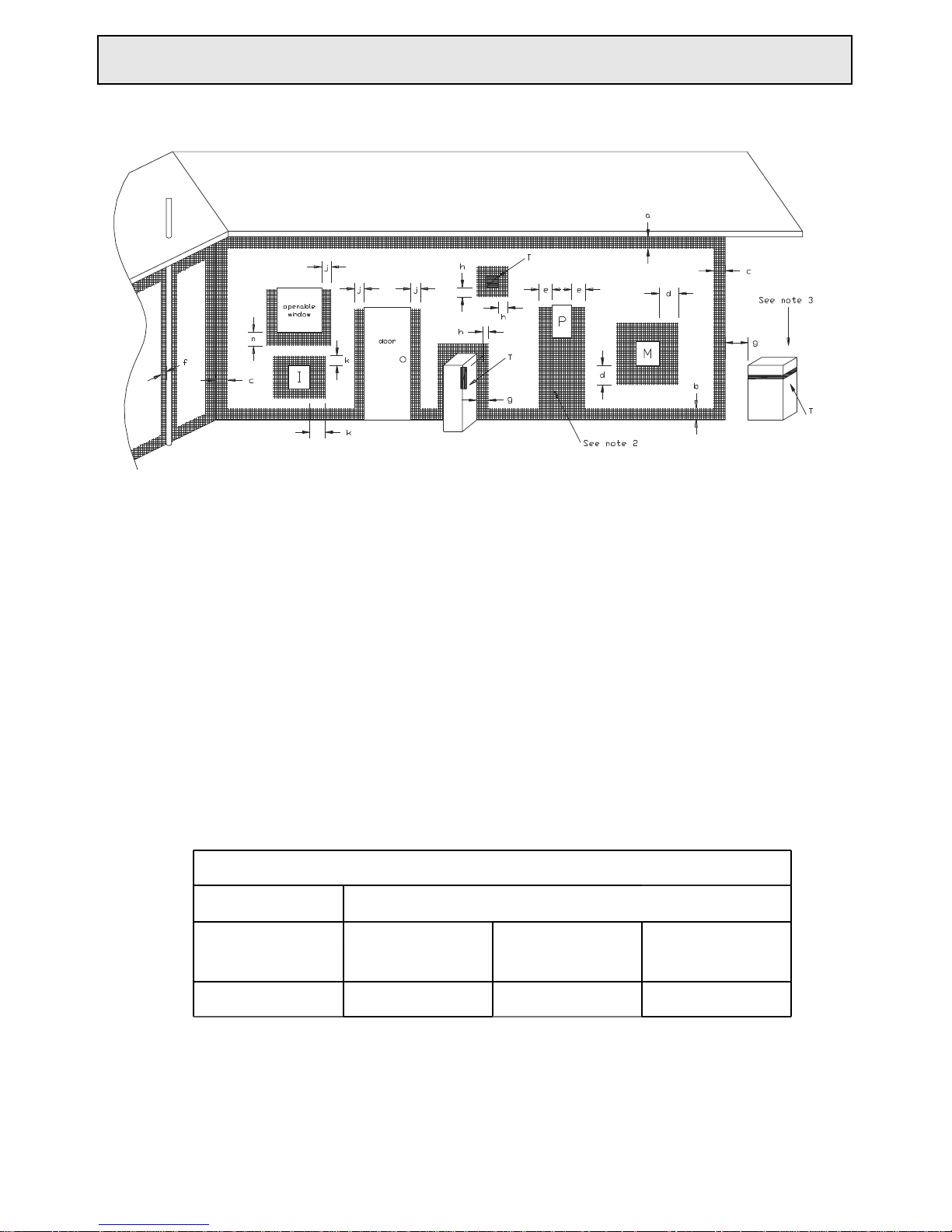
T=flue terminal
I =Mechanical air inlet
M=Gas meter
P = Electricity meter or
fuse box
Shading indicates
prohibited
areas for flue terminals
a
Below eaves, balconies or other projections:
Appliances up to 50 MJ/h input
Appliances over 50 MJ/hinput
From the ground or above a balcony
From a return wall or external corner
From a gas meter (M)
From an electricit y meter or fuse box (P)
From a drain or soil pipe
Horizontally from any building structure (unless appliance approved for closer
installation) or obstruction facing a terminal
From any other flue terminal, cowl, or combustion air intake
Horizontally from an openable window, door, non-mechanical air
inlet, or any other opening into a building, with the exception of
sub-floor ventilation:
Appliances up to 150 MJ/hinput
Appliances over 150 MJ/h input
From a mechanical air inlet, including a spa blower
MIN. CLEARANCE
(mm)
300
500
300
500
1000
500
150
g
500
500
h
j
500
150
150
k
n
Vertically below an openable window, non-mechanical air inlet
or any other opening into a building, with the exception of
sub-floor ventilation
See table below
NOTES:
I. All distances are measured vertically or horizontally along the wall to a point
in line with the nearest part of the terminal.
2. Prohibited area below electricity meter or fuse box extends to ground level.
3. See clause 5.13.6.6 for restrictions on a flue terminal under a roofed area.
4. See Appendix J, Figure JI (a) and J2(a) for clearances required from a flue
terminal to a LP Gas cylinder. A flue terminal is considered to be a source of ignition.
MINIMUM CLEARANCES REQUIRED FOR BALANCED FLUE TERMINALS
OR THE FLUE TERMINALS OF OUTDOOR APPLIANCES
CLEARANCES 'n' (mm)
Space heaters
All other appliances
Up to 50
MJ/h
Input
UP to 50 MJ/h
input
Over 50 MJ/h & up
to 150 MJ/h
Over 150 MJ/h
input
150
500
1000
1500
b
c
d
e
f
7/8/2017
Ver. 1
Installation Instructions Kemlan Portrait Power Flue Horizon Gas Fireplaces
Installation Instructions Kemlan Portrait Power Flue Horizon Gas Fireplaces
7/8/2017
Ver. 1
5
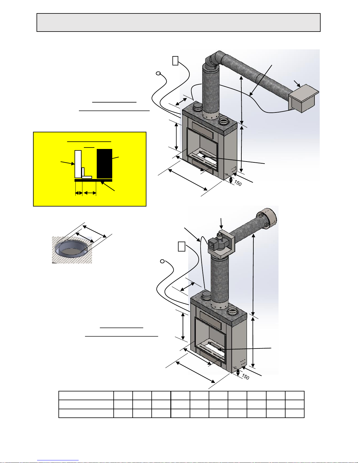
E
C+
B
C+
* TO UNDERSIDE OF FLUE WITH EXTERNAL FAN (1300mm)
** TO UNDERSIDE OF FLUE WITH INTERNAL FAN (1010mm)
+ OUTER BOX SIZE ONLY, NOT INCLUDING LIP FRAME
Power Flue
EXTERNAL FAN
CASING
3 PIN PLUG 240
VOLT 10 AMP
ISOLATING SWITCH
3 PIN PLUG 240 VOLT
10 AMP ISOLATING
SWITCH
ON/OFF SWITCH
TO BURNER
A
D
INTERNAL FAN
SINGLE SIDED-REAR EXIT
EXTERNAL FAN
SINGLE SIDED-SIDE EXIT
ON/OFF SWITCH
TO BURNER
GAS INLET
CONNECTION UNDER
BURNER TYP.
ELECTRICAL LOOM
CONNECTOR BURNER
TO FAN
ELECTRICAL LOOM
CONNECTOR BURNER
TO FAN
REMOVABLE GAS
BURNER PEBBLE/COAL
OR LOG
AGA APPROVED
GAS COWL
INTERNAL FAN
CASING
F
J
SPIGGOT TYP. DETAIL
G
SINGLE SIDED A B C+ D E F G H I
J
700 PORTRAIT 700 600 365 1087 1000 178 225 10 15
*/**
850 PORTRAIT 850 600 405 1182 1095 225 275 10 15
*/**
10MM
SHEETING
H
I
LIP FRAME DETAIL
TYP.
FRONT OF
FIREPLACE
LIP TRIM
D
J
B
E
A
GAS INLET
CONNECTION UNDER
BURNER TYP.
REMOVABLE GAS
BURNER PEBBLE/COAL
OR LOG

Power Flue with Internal Fan
HEAT TRANSFER
BOX
SILENCER
8” x 900
REDUCER
7” – 6”
8” – 6”
9” – 6”
10” – 6”
12” – 6”
14”-- 6”
GAS COWL
COOLING ROTOR
INBUILT THERMAL
OVERLOAD
COOLING IMPELLER
6” x 900
12.5” x 900
12.5” x 200 VENTED FLUE
Note:
Power flue Horizontal runs greater than 5 meters in length may be compromised by
fluctuations in power. Flue runs greater than 5 meters when tested with underload power
of 15% caused the fan to cut out and burner to turn off and require resetting.
Resetting can be done by turning power off and on. Should power be consistent in supply
then longer flue runs can be recommended and burner will perform correctly.
7/8/2017
Ver. 1
6
Installation Instructions Kemlan Portrait Power Flue Horizon Gas Fireplaces

Power Flue with External Fan
SILENCER
8” x 900
REDUCER
7” – 6”
8” – 6”
9” – 6”
10” – 6”
12” – 6”
14 ”-- 6”
WALL MOUNTED
FAN
2x 8” 45 DEG
12” – 8”
REDUCING CAP
6” x 900
12.5” x 900
2x 6” 45 DEG
12.5” x 200 VENTED FLUE
10MM GAP BETWEEN
END OF FLUE TO WALL
Note:
Power flue Horizontal runs greater than 5 meters in length may be compromised by
fluctuations in power. Flue runs greater than 5 meters when tested with underload power
of 15% caused the fan to cut out and burner to turn off and require resetting.
Resetting can be done by turning power off and on. Should power be consistent in supply
then longer flue runs can be recommended and burner will perform correctly.
7/8/2017
Ver. 1
7
Installation Instructions Kemlan Portrait Power Flue Horizon Gas Fireplaces

8
Installation Instructions Kemlan Power Flue Horizon Gas Fireplaces
7/8/2017 Ver. 1
FRAMING DIMENSIONS
SINGLE SIDED
C
B
A
C* INCLUDING 10mm PLASTERBOARD
SINGLE SIDED A B C C*
700 PORTRAIT 1056 1197 370 390
850 PORTRAIT 1145 1292 410 430

7/8/2017
Ver. 1
300 MIN. TO VERTICAL
SURFACE (CEILING)
110 MM MIN.
FAN ( 300MM x 105MM )
137 MM.
OPTIONAL SECOND
FAN
TIMBER SUPPORT
REQUIRED
SPIRAL DUCT 150MM MAX.
- WITH NO AIR POCKETS
- CANNOT BE VENTED
UNDERNEATH UNIT
INSULATION BOARD
SECTION A-A
HEATZONE
ACTIVE FLUE
CASING
FULL WELD
HEAT ZONE CONVERSION
9
Installation Instructions Kemlan Portrait Power Flue Horizon Gas Fireplaces

10
7/8/2017
Ver. 1
AGA APPROVED
GAS COWL
APPROVED
FLASHING
SECTIONS
25MM MIN. FLUE
CLEARANCE TO
TIMBER
HORIZON GAS
FIREPLACE
10MM COMPRESSED FIBRE
CEMENT SHEET BETWEEN
UNIT AND BOTTOM SUPPORT
FRAMING
FRAMEWORK
AND 10MM WALL
LINING BY
INSTALLER
150MM MIN .
110MM MIN .
Installation Instructions Kemlan Portrait Power Flue Horizon Gas Fireplaces
 Loading...