

Horizon FIREPLACES CANTLEVER 700, CANTLEVER 1500, CANTLEVER 1100, LOW LINE 850, LOW LINE 1100 Installation Instructions Manual
...
----FIREPLACES----
Installation Instructions
Horizon Power Flue Gas Fireplaces
28/02/2019 Ver. 25
1
SINGLE SIDED MODELS
SUITABLE GAS BURNER OPTION
CANTILEVER
700 Cantilever 700 Mk2Pebble
700 Mk2Coal
700 Ironbark LogMk4
1100 Cantilever 1000 Mk2 Pebble
1000 Mk2Coal
850 Ironbark Log Mk4
1500 Low Line 1400 Mk2 Pebble
1400 Mk2Coal
DOUBLE SIDED MODELS
Power Flue approved for the
following models:
Installation Instructions Kemlan Power Flue Horizon Gas Fireplaces
Location Requirements
Power flue systems utilizes a fan assisted draft to
ensure products of combustion are exited through a
flue terminal either horizontally or vertically
terminated.
The following A.G.A location requirements for flues
are to be observed when installing a powered flue
system.
SEE NEXT PAGE FOR LOCATION EQUIREMENTS
Ventilation Requirements:
Rooms with gas open fireplaces require as per
clause 6.10.9.5 in AS/NZS5601.1:2013, one or more
ventilation openings with a combined free ventilation
area of not less than the equivalent cross sectional
area of the flue cowl shall be provided for each
decorative flame effect fire and calculations based
on clause 6.4.4
Model Type 2: Power Flue
Decorative Gas Fireplace
DATA PLATE: Refer to information on page 16 of this
Instruction booklet in respect to gas pressure,
consumption and gas type, Natural, ULPG or LPG.
Data Plate is located under the gas burner and is
accessed by lifting front access panel or removing
base plate.
700 Low Line 700 Mk2Pebble
700 Mk2Coal
700 Ironbark LogMk4
850 Low Line 800 Mk2 Pebble
800 Mk2Coal
850 Ironbark Mk4
1100 Low Line 1000 Mk2Pebble
1000 Mk2Coal
850 Ironbark LogMk4
1500 Low Line 1400 Mk2 Pebble
1400 Mk2Coal
2000 Low Line 1800 Mk2 Pebble
1800 Mk2Coal
700 Low Line 700 Mk2Pebble
700 Mk2Coal
700 Ironbark LogMk4
850 Low Line 800 Mk2 Pebble
800 Mk2Coal
850 Ironbark Mk4
1100 Low Line 1000 Mk2Pebble
1000 Mk2Coal
850 Ironbark LogMk4
1500 Low Line 1400 Mk2 Pebble
1400 Mk2Coal
2000 Low Line 1800 Mk2 Pebble
1800 Mk2Coal
28/02/2019 Ver. 25
NOTE: The chimney in which the appliance is installed
is not to be considered as a ventilation opening.
PLEASE NOTE:
All power flue external joints (inc. flue joints,
attenuator, Fan, etc.) must be sealed with
approved heat rated (149°C minimum
continuous exposure rating) foil tape
after joining sections! Internal flues do not
need to be sealed with foil tape.
2

Installation Instructions Kemlan Power Flue Horizon Gas Fireplaces
T=flue terminal
I =Mechanical air inlet
M=Gas meter
P = Electricity meter or fuse
box
Shading indicates
prohibited
areas for flue terminals
a
Below eaves, balconies or other projections:
Appliances up to 50 MJ/h input
Appliancesover 50 MJ/h input
From the ground or above a balcony
From a return wall or external corner
From a gas meter (M)
From an electricity meter or fuse box (P)
From a drain or soil pipe
Horizontally from any building structure (unless appliance
approved for closer installation) or obstruction facinga terminal
From any other flue terminal, cowl, or combustion air intake
Horizontally from an openable window, door, non-mechanical air
inlet, or any other opening intoa building, with the exception of sub-floor ventilation:
Appliances up to 150 MJ/h input
Appliances over 150 MJ/h input
From a mechanical air inlet, including a spa blower
MIN. CLEARANCE(mm)
300
500
300
500
1000
500
150
g
500
500
h
j
500
150
150
k
Vertically below an openable window, non-mechanical air inlet
or any other opening into a building, with the exception of sub-
floor ventilation
See table below
NOTES:
I. All distances are measured vertically or horizontally along the wall to a point
in line with the nearest part of the terminal.
2. Prohibited area below electricity meter or fuse box extends to ground level.
3. See clause 5.13.6.6 for restrictions on a flue terminal under a roofed area.
4. See Appendix J, Figure JI (a) and J2(a) for clearances required from a flue
terminal to a LP Gas cylinder. A flue terminal is considered to be a source of ignition.
MINIMUM CLEARANCES REQUIRED FOR BALANCED FLUE TERMINALS
OR THE FLUE TERMINALS OF OUTDOOR APPLIANCES
CLEARANCES 'n' (mm)
Space heaters
All other appliances
Up to 50
MJ/h
Input
UP to 50 MJ/h
input
Over 50 MJ/h& up
To 150 MJ/h
Over 150 MJ/h
input
150
500
1000
1500
b
c
d
e
f
28/02/2019
Ver. 25
n
3

Before Installation
The Power flue system shall be installed by authorized
personnel in accordance with the manufacturer’s
installation instructions, local gas fitting regulations,
municipal building codes, electrical wiring regulations,
and any other statutory regulations. Contact your local
building authorities about restrictions and installation
inspections that may be required. If in doubt contact
your local dealer or Kemlan’s Head office.
IMPORTANT AUSTRALIAN CODES:
• Australian Standards AS 5601 Gas Installation
• Australian Standards AS 3000 Electrical
Important Safety Notes
• Comply with all instructions in manual
including clearances to combustible material.
• Do not operate without fully assembling
all components.
• All open gas fires require ventilation in the
room.
• Do not connect to any other air distribution duct or
system.
• An A.G.A approved cowl is required at flue terminal.
• Refer to the table below for flue diameter and flue
cowl size.
• Air movement of systems- A decorative gas log fire
must not be installed where the operation of any
ventilation system, fan or air blower could in any
circumstances cause the air pressure to be less than
atmospheric at the appliance.
• Do not block or restrict chimney.
• After installing appliance check that the flue draws
well with smoke pellet.
• Kemlan recommends that all gas fires be serviced
every year.
• All gas units must be fitted by a licensed gas fitter.
• It is the responsibility of the gas fitter to follow the
regulations set out in the Gas Code that dictate the
procedures to follow when installing a gas appliance,
particularly regarding gas pipe sizing and checking of
pressures.
Installation
1 The Power flue system is supplied with all
required electrical fittings. Work needs to be
undertaken by a licensed electrician if extending
wiring. Wiring requires clearance of minimum
100mm to flues and fireplace body due to heat. See
Wiring diagram page15. Wiring must be positively
secured away from heat source.
2 An isolation switch needs to be provided if
connecting within fireplace framework.
3 Build frame to specifications provided. Note: 80mm
clearance above fireplace and 5mm to front surface
of firebox.
4 Unit located on 10mm fiber cement sheeting.
Sheeting required for access to gas burner.
5 Unit and flues to be installed prior to plastering.
6 Gas line run to desired position prior to plastering.
7 Clearance of 25mm to vertical flue.
8 Allow for a minimum flue height of 3.6m.
9 All flue components to be riveted together.
10 Rooms with Gas Open Fires require fresh air vents,
refer to page 2 , Ventilation Requirements, for each
Decorative Gas and Coal Fire.
11 Important: Both caps to stay off if heat zone is not
used.
12 Important: if a heat zone kit with fan is used, the
unused outlet must remain uncapped.
13 Vent (240mm x 90mm) supplied by Kemlan is
required to ventilate chase to room
Installation Instructions Kemlan Power Flue Horizon Gas Fireplaces
28/02/2019 Ver. 25
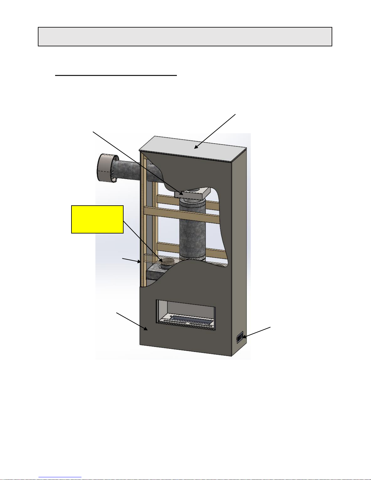
Rear clearances to
combustible material
Cantilever : 0mm
Low line: 25mm
4
28/02/2019 Ver. 25
WALL LININGS BY
INSTALLER
COMBUSTIBLE
FRAMING
ASSEMBLY REQUIREMENTS : LOWLINE SINGLE SIDED MODEL SHOWN
CEILING
IMPORTANT:
VENTILATION INTO
CHASE FROM VENT
240MM X 90MM
(SUPPLIED)
Installation Instructions Kemlan Power Flue Horizon Gas Fireplaces
INTERNAL FAN
ASSEMBLY
IMPORTANT: BOTH
CAPS NEEDS TO STAY
OFF, IF HEAT ZONE IS
NOT USED
5

Installation Instructions Kemlan Power Flue Horizon Gas Fireplaces
B*
D
* TO UNDERSIDE OF FLUE WITH EXTERNAL FAN (1300mm)
** TO UNDERSIDE OF FLUE WITH INTERNAL FAN (1010mm)
+ BOX SIZE ONLY NOT INCLUDING LIP FRAME
EXTERNAL FAN
CASING
3 PIN PLUG
240 VOLT
10 AMP
ISOLATING
SWITCH
3 PIN PLUG
240 VOLT
10 AMP
ISOLATING
SWITCH
ON/OFF SWITCH
TO BURNER
A*
D
INTERNAL FAN
REAR EXIT
EXTERNAL FAN
SIDE EXIT
ON/OFF SWITCH
TO BURNER
GAS INLET
CONNECTION UNDER
BURNER TYP.
ELECTRICAL LOOM
CONNECTOR BURNER
TO FAN
ELECTRICAL LOOM
CONNECTOR BURNER
TO FAN
REMOVABLE GAS
BURNER
AGA APPROVED
GAS COWL
INTERNAL FAN
CASING
A*
B*
F
K
K
SPIGGOT TYP. DETAIL
G
* TO UNDERSIDE OF FLUE WITH EXTERNAL FAN (1300mm)
** TO UNDERSIDE OF FLUE WITH INTERNAL FAN (1010mm)
+ BOX SIZE ONLY NOT INCLUDING LIP FRAME
I
FRONT OF
FIREPLACE
SECTION VIEW
Z-Z
Y
DETAIL Y -
LIP TRIM ASSEMBLY
Z
Z
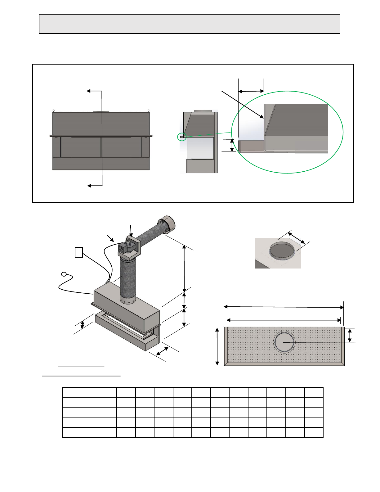
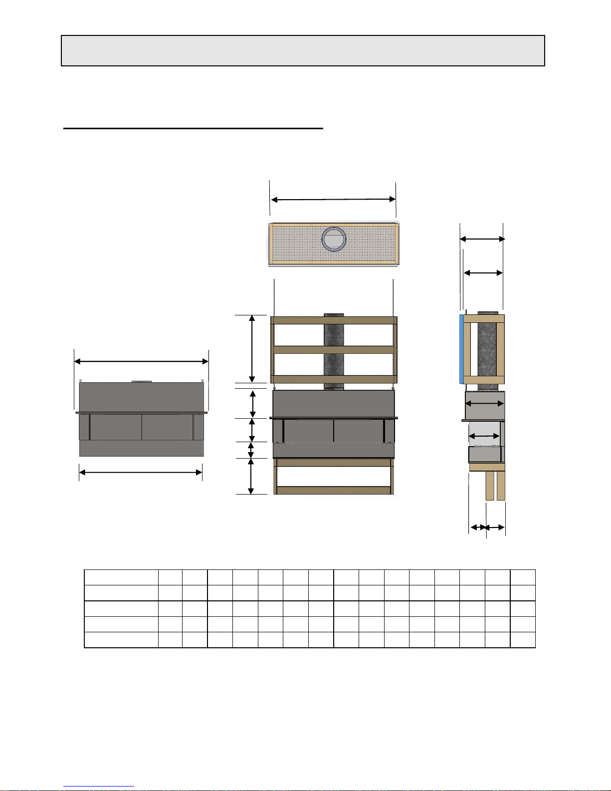
Measurement and Specifications of P.F: LOWLINE
PLASTER TRIM 50mm,
100mm &150mm
TRIMS OPTIONAL FOR
BOTH MODELS
IMPORTANT: BOTH
CAPS NEEDS TO STAY
OFF, IF HEAT ZONE IS
NOT USED
Z
NOTE: THE “J” MEASUIREMENT IS TO THE UNDERSIDE OF AN 8” FLUE , THE DIAMETER OF THE 8” INCH FLUE IS 203mm.
H
C
C
J
J
E
E
J
SINGLE SIDED A B C+ D E F G H I J K
700 LOW LINE
700
280
365
770
1000
178
225
10 15
157
*/ **
850 LOW LINE
850
286
405
870
1095
225
275
10 15
183
*/ **
1100 LOW LINE
1100
286
405
870
1345
225
275
10 15
202
*/ **
1500 LOW LINE
1500
286
435
1000
1746
250
300
10 15
208
*/ **
2000 LOW LINE
2000
286
435
1000
2246
250
300
10 15
208
*/ **
DOUBLE SIDED
A B C+ D E F G H I J K
700 LOW LINE
700
280
450
770
1000
250
300
10 15
225
*/ **
850 LOW LINE
850
286
450
870
1095
250
300
10 15
225
*/ **
1100 LOW LINE
1100
286
450
870
1345
250
300
10 15
225
*/ **
1500 LOW LINE
1500
286
435
1000
1746
300
350
10 27
218
*/ **
2000 LOW LINE
2000
286
435
1000
2246
300
350
10 27
218
*/ **
28/02/2019
Ver. 25
6
28/02/2019 Ver. 25
ON/OFF
SWITCH TO
BURNER
INTERNAL FAN
CANTILEVER – REAR EXIT
G
F
C
B
3 PIN PLUG 240
VOLT 10 AMP
ISOLATING
SWITCH
ELECTRICAL LOOM
CONNECTOR BURNER
TO FAN
AGA APPROVED
GAS COWL
INTERNAL FAN
CASING
E
I
SPIGGOT TYP. DETAIL
D
X
X
W
42*
FRONT OF
FIREPLACE
SECTION VIEW
X-X
DETAIL W -
LIP TRIM ASSEMBLY
Installation Instructions Kemlan Power Flue Horizon Gas Fireplaces
Measurement and Specifications of P.F: CANTILEVER
7
SINGLE SIDED A A1 B C D D1 E F G H I
CANTLEVER 700 1190 1270 480 455 228 279 177 405 336 1010 170
CANTLEVER 1100 1420 1505 480 455 228 279 177 405 336 1010 188
CANTLEVER 1500 1850 1930 480 455 254 304 177 405 336 1010 224
CANTILEVER 2000 2203 2283 480 455 254 304 177 405 336 1010 189
A1
A
H
20
Installation Instructions Kemlan Power Flue Horizon Gas Fireplaces
MODEL A B C D E F G H I * J K L M N O
CANTLEVER 700 1190 1270 480 336 280 177 440 405 1250 150 TBD 80 470 190 215
CANTLEVER 1100 1420 1505 480 336 280 177 440 405 1485 150 TBD 80 470 190 215
CANTLEVER 1500 1850 1930 480 336 280 177 440 405 1910 150 TBD 80 470 190 215
CANTILEVER 2000 2203 2283 480 336 280 177 440 405 2263 150 TBD 80 470 190 215
A
B
K
L
D
F
J
C
M
N
O
E
I *
* FRAME WIDTH
G
H
FRAMING DIMENSIONS: CANTILEVER
28/02/2019 Ver. 25 8
Installation Instructions Kemlan Power Flue Horizon Gas Fireplaces
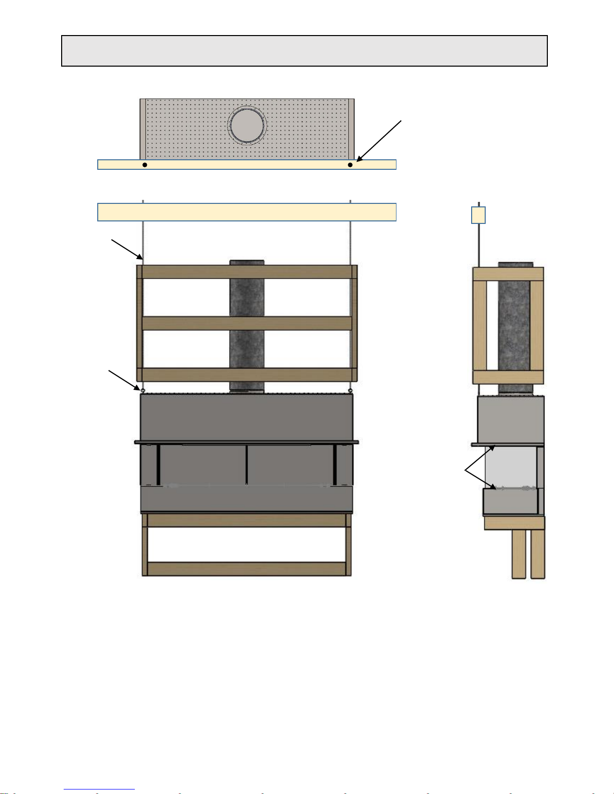
• Eyelets on the unit are supplied for attaching a turn buckle system, 6-
8mm threaded rod is required with a nut and washer either side of a
sufficient supporting roof member. Alternatively, a stainless steel wire
with a minimum 1mm diameter or heavier and a minimum break load of
130kg can also be used.
• Once hooks have been attached to the eyelets the turn buckle can then
be simply wound up to take the tension.
• Tighten the turn buckle until both the top and bottom glass runners are
parallel.
• Removable glass panel can now be placed in position allowing an even
gap between glass and underside of channel.
DRILL THROUGH THE
BEAM , RAFTER OR
FRAMING IF REQUIRED
AND PUSH THROUGH
THE THREADED ROD.
EYELET
MAKE SURE THESE
PLANES ARE PARALLEL,
AND MAKE SURE ALL
CORNERS ARE SQUARE
THREADED ROD
28/02/2019 Ver. 25 9
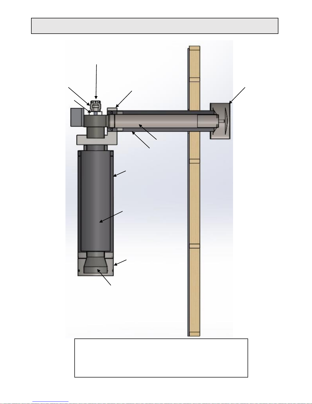
Power Flue with Internal Fan
HEAT TRANSFER
BOX
SILENCER
8” x 900
REDUCER
7” – 6”
8” – 6”
9” – 6”
10” – 6”
12” – 6”
14”-- 6”
GAS COWL
COOLING ROTOR
INBUILT THERMAL
OVERLOAD
COOLING IMPELLER
6” x 900
12.5” x 900
Installation Instructions Kemlan Power Flue Horizon Gas Fireplaces
12.5” x 200 VENTED FLUE
Note:
Power flue Horizontal runs greater than 5 meters in length may be compromised by
fluctuations in power. Flue runs greater than 5 meters when tested with underload power
of 15% caused the fan to cut out and burner to turn off and require resetting.
Resetting can be done by turning power off and on. Should power be consistent in supply
then longer flue runs can be recommended and burner will perform correctly.
28/02/2019
Ver. 25
10
 Loading...