

Page 1

COLLATOR
VAC-100
Important Information
- This manual is designed to help you to install, operate and maintain Collator, VAC-100.
Read, understand and keep this manual in a safe and convenient place.
- Do not operate VAC-100 until you read and understand the instructions in this manual.
- Horizon International Inc. shall not be liable for incidental consequential damages
resulting from : improper or inadequate maintenance by customer; unauthorized modification or misuse; operation outside of the environmental specifications for the product.
- Horizon International Inc. pursues a policy of continuing improvement in design and
performance of the product. Therefore, the product design and specifications are subject to
change without prior notice and without our legal obligation.
- All rights are reserved. No part of the manual may be photocopied, reproduced or
translated to another language without the prior written consent of Horizon International Inc.
020702/VAC100/09E/DV
I
UM201050-09
Page 2

Safety Precautions
- The signal word WARNING indicates a potentially hazardous situation which, if not
avoided, could result in death or serious injury.
- The signal word CAUTION indicates a potentially hazardous situation which, if not
avoided, may result in damage on machines. It may also be used to alert against unsafe
practices.
- Read and understand all safety instructions with signal word such as WARNING and
CAUTION. If safety instructions are ignored, personal injury may result.
- Horizon International Inc. cannot anticipate every possible situation that might involve
a potential hazard. The instructions in this manual and warning labels on the machine are
therefore not all inclusive.
- All equipment shall be locked out or tagged out to protect against accidental or inadvertent operation when such operation could cause injury to personnel. Do not attempt to
operate any switch, valve, or other energy isolating device where it is locked or tagged out.
- Do not operate the machines when any covers are removed.
- Some of the drawings in this manual show the machine uncovered for explaining the
detail or inside of machine.
II
Page 3

CONTENTS
Important Information ............................................................................................I
Safety Precautions .................................................................................................... II
1. Before You Begin
1-1 Specifications ...................................................................................................... 2
1-1-1 VAC Series Specifications .............................................................................2
1-1-2 Receiving Tray (Option) Specifications ......................................................... 3
1-2 Machine Descriptions ........................................................................................ 4
1-2-1 Overview ........................................................................................................ 4
1-2-2 Feed Section ................................................................................................... 5
1-2-3 Operation Panel ..............................................................................................6
[1] Main Page.......................................................................................................6
[2] Set 1 Page ....................................................................................................... 8
[3] Set 2 Page ....................................................................................................... 9
[4] Program Page ................................................................................................. 10
[5] Memory Page ................................................................................................. 11
[6] Preset Input Page ............................................................................................ 12
1-2-4 Remote Controller ..........................................................................................13
1-2-5 Receiving Tray (CCR)....................................................................................14
1-2-6 Receiving Tray (CCR-DX) ............................................................................ 15
1-2-7 Stacker (ST-20) .............................................................................................. 16
1-2-8 Stacker (ST-20R)............................................................................................ 17
1-2-9 Stacker (ST-40) .............................................................................................. 18
1-2-10 Stacker (ST-60) ............................................................................................ 19
1-2-11 Hand Marry Unit (HMU-100) ...................................................................... 21
1-3 Accessories .......................................................................................................... 22
1-4 Consumables and Options ................................................................................ 24
2. Operation Procedures
2-1 Power ON ........................................................................................................... 26
2-2 Preparation for Operation ................................................................................27
2-2-1 Tower ON/OFF and Delivery Direction Setup .............................................. 27
2-2-2 Collating Sheet Preparation ............................................................................ 28
2-2-3 Small Size Sheet Setup ................................................................................... 30
2-2-4 Feed Height Adjustment ................................................................................. 32
2-2-5 Blower Adjustment.........................................................................................32
III
Page 4

2-2-6 Double Feed Stop Plate Height Adjustment...................................................33
2-2-7 Separate Nose Adjustments ............................................................................33
2-2-8 Delivery Section Setup ...................................................................................34
[1] Bulging Nose and Delivery Roller Setup ....................................................... 34
[2] Weight Setup ..................................................................................................35
[3] Delivery Air Adjustment ................................................................................36
2-2-9 Tray Unit Setup .............................................................................................. 37
[1] When CCR or CCR-DX Is Used .................................................................... 37
[2] When ST-20/ST-20R Is Used ........................................................................40
2-2-10 Setup in Main Page.......................................................................................41
2-2-11 Hand Marry Unit Setup (HMU-100: Accessary) ......................................... 42
2-3 Collating Operation ...........................................................................................43
2-3-1 Sheet Thickness Calibration ...........................................................................43
2-3-2 Collating Operation ........................................................................................44
2-4 Feed Error Indication and Remedy .................................................................45
2-5 Program Collation ............................................................................................. 47
2-5-1 Double Cycle ..................................................................................................47
2-5-2 Dual Cover Feed ............................................................................................. 49
2-5-3 Tab Insert ........................................................................................................ 51
2-6 Job Memory ....................................................................................................... 53
2-7 Right Side Delivery ............................................................................................54
2-8 Hand Marry ....................................................................................................... 55
3. Troubleshooting
3-1 Error Indication and Remedy .......................................................................... 58
3-2 When Misfeeding Occurs ..................................................................................59
3-3 When Double Feeding Occurs ..........................................................................59
3-4 Sheets Are Fed on the Skew ..............................................................................60
3-5 Paper Jam in Transport Conveyor .................................................................. 60
3-6 Sheet from Hand Marry Unit Is Jammed ....................................................... 61
3-7 Collating Operation Does Not Start Even If Pressing Start Buttom ............ 61
3-8 Fuse and Breaker Check ...................................................................................62
3-9 Pump Does Not Work ........................................................................................ 65
IV
Page 5

4. Maintenance
4-1 Daily Cleaning ....................................................................................................68
4-1-1 Feed Ring .......................................................................................................68
4-1-2 Transport Belt .................................................................................................69
4-2 Monthly Cleaning .............................................................................................. 70
4-2-1 Bin Sensor ...................................................................................................... 70
4-2-2 Delivery Sensor ..............................................................................................70
4-3 Double Feed Stop Plate Replacement .............................................................. 71
4-4 Feed Error Sensor Cleaning ............................................................................. 72
5. Move and Installation
5-1 Collator Installation ...........................................................................................74
5-2 Blower Box Installation .....................................................................................75
5-3 System Switch Set Up ........................................................................................77
5-4 Cable Connection ...............................................................................................78
5-5 Receiving Tray Installation ............................................................................... 79
5-5-1 CCR/CCR-DX ................................................................................................ 79
5-5-2 ST-20/ST20R..................................................................................................80
5-6 EAB-100 Extra Air Blower (Option) Installation ...........................................82
5-7 VAC-100a Right Side Unit (Option) Attachment ...........................................87
5-7-1 Accessories .....................................................................................................87
5-7-2 How to Attach ................................................................................................89
5-8 HMU-100 Hand Marry Unit (Option) Installation .........................................97
5-8-1 Accessories .....................................................................................................97
5-8-2 Hand Marry Unit (HMU-100) Installation .....................................................98
5-8-3 Cable Connection ........................................................................................... 101
V
Page 6

VI
Page 7

1. Before You Begin
1. Before You Begin
1-1 Specifications ........................................................................................... 2
1-2 Machine Descriptions .............................................................................. 4
1-3 Accessories ............................................................................................... 22
1-4 Consumables and Options ...................................................................... 24
1
Page 8

1. Before You Begin
1-1 Specifications
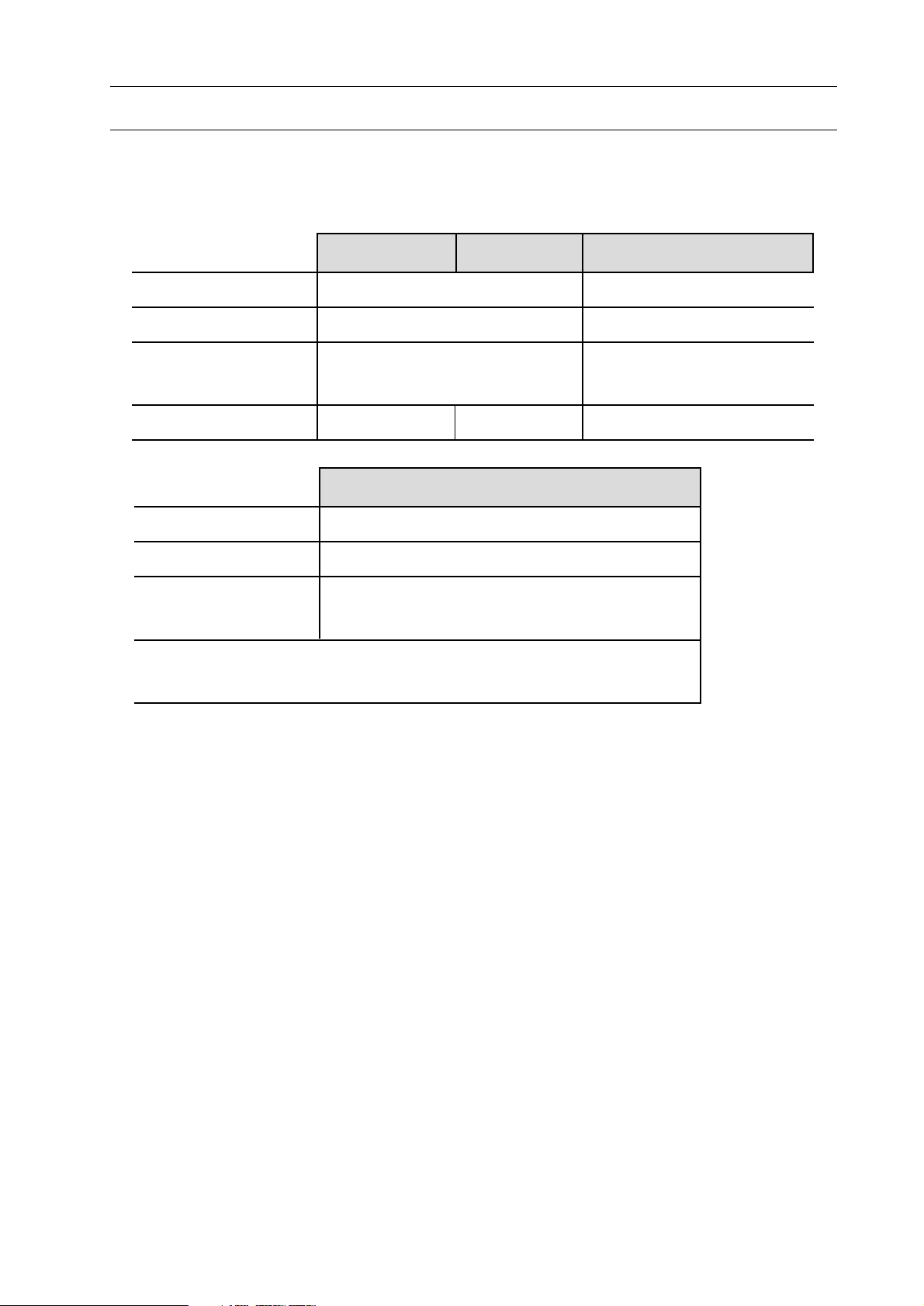
1-1-1 VAC Series Specifications
Module Type VAC-100a (Main Module)
VAC-100m (Extension Module)
VAC-100c (Rear Delivery Module)
Number of Bins 10, 20, 30, 40, 50, 60
Sheet Size 148 x 148 mm to 350 x 500 mm
(5.8" x 5.8" to 13.8" x 19.7')
Bin Pile Height 55 mm (2.2")
Paper Weight Range 52 gsm to 208 gsm
Collating Speed 8,000 sets/hr (Single or 2 to 3 towers installation and Straight Receiving)
5,000 sets/hr (4 towers installation and Straight Receiving)
4,500 sets/hr (5 towers installation and Straight Receiving)
4,000 sets/hr (6 towers installation and Straight Receiving)
Error Detection Miss, Double and Jam detection system (Photocell)
Error Monitor Eight sets of Feed Error Monitors
Power 3-Phase 200 V 50/60 Hz
3-Phase 220 V 60 Hz 10.4A
Single Phase 230 V 50 Hz 10.4A
Power Consumption 200 V 1,500 W / 220 V 1,700 W / 230 V 1,800 W
Motors 1,200 W x 1 / 400 W x 1 / 200 W x 1 / 100 W x 1
60 W x 1 (only a, c towers)
Machine Weight VAC-100a : 290 kg (639.5 lb)
VAC-100m : 290 kg (639.5 lb)
VAC-100c : 290 kg (639.5 lb)
The machine design and specifications are subject change without any notice.
2
Page 9
1. Before You Begin
1-1 Specifications
1-1-2 Receiving Tray (Option) Specifications
Model CCR CCR-DX ST-20 and ST-20R
Max. Sheet Size 318 x 470 mm (12.5" x 18.5") 320 x 450 mm (12.6" x 17.7")
Min. Sheet Size 148 x 210 mm (5.9" x 8.3") 128 x 185 mm (5.1" x 7.3")
Max. Pile Height A5 to A4 : 170 mm (6.7") 320 mm (12.6")
A4 to A3 : 100 mm (3.9")
Machine Weight 56 kg (123.5 lb) 64 kg (141.2 lb) 56 kg (123.5 lb)
Model HMU-100
Max. Sheet Size 350 x 500 mm (14" x 20")
Min. Sheet Size 120 x 148 mm (4.7" x 5.8")
Max. Sheet Height 80 gsm (21.3 lb) 50 sheets (5 mm)
Min. Sheet Height 80 gsm (21.3 lb) 1 sheets (0.1 mm)
The HMU-100 can be used with maximum of two-tower VAC-100.
The HMU-100 can not be connected with c-tower VAC-100.
The machine design and specifications are subject change without any notice.
3
Page 10
1. Before You Begin
1-2 Machine Descriptions
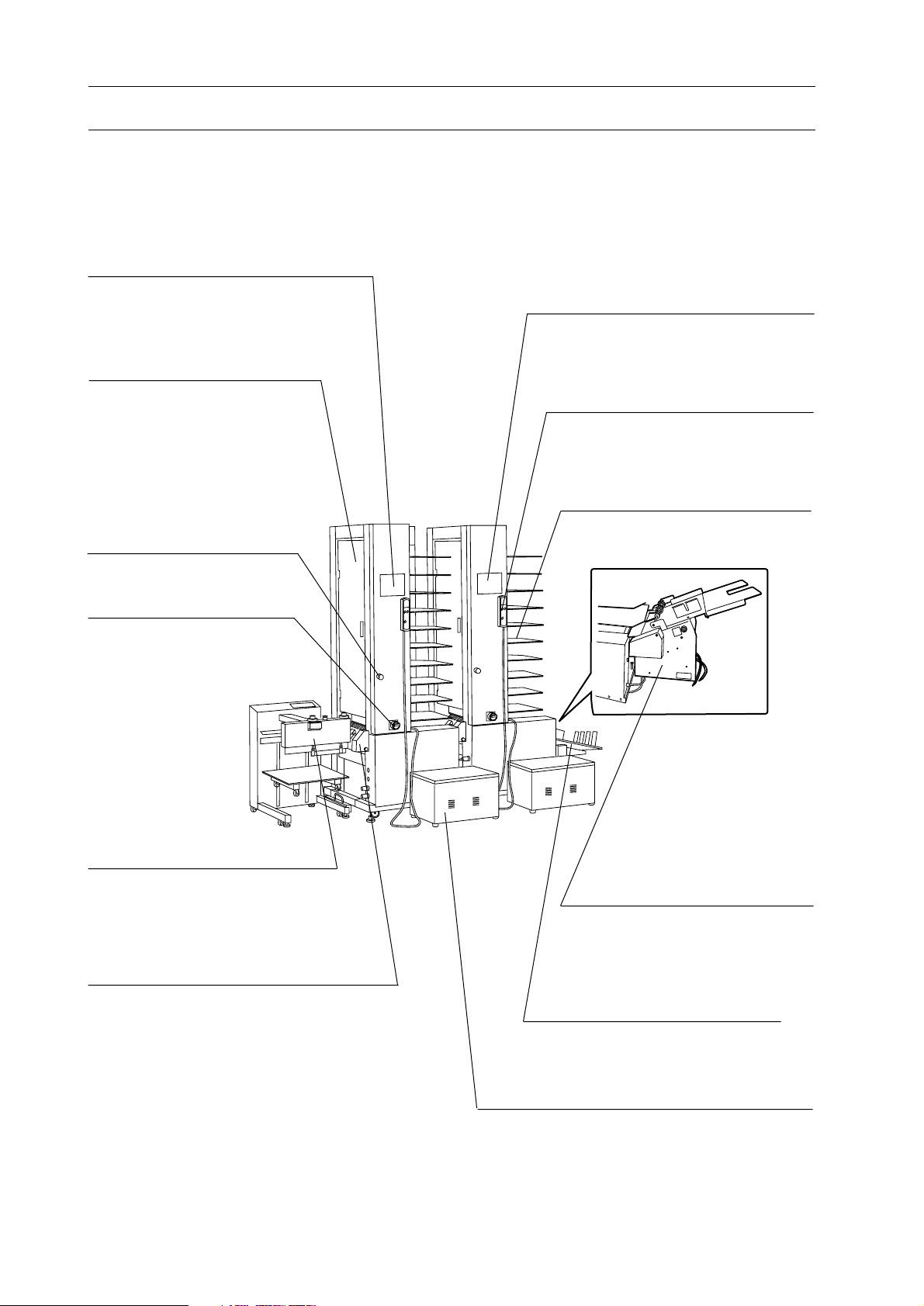
1-2-1 Overview
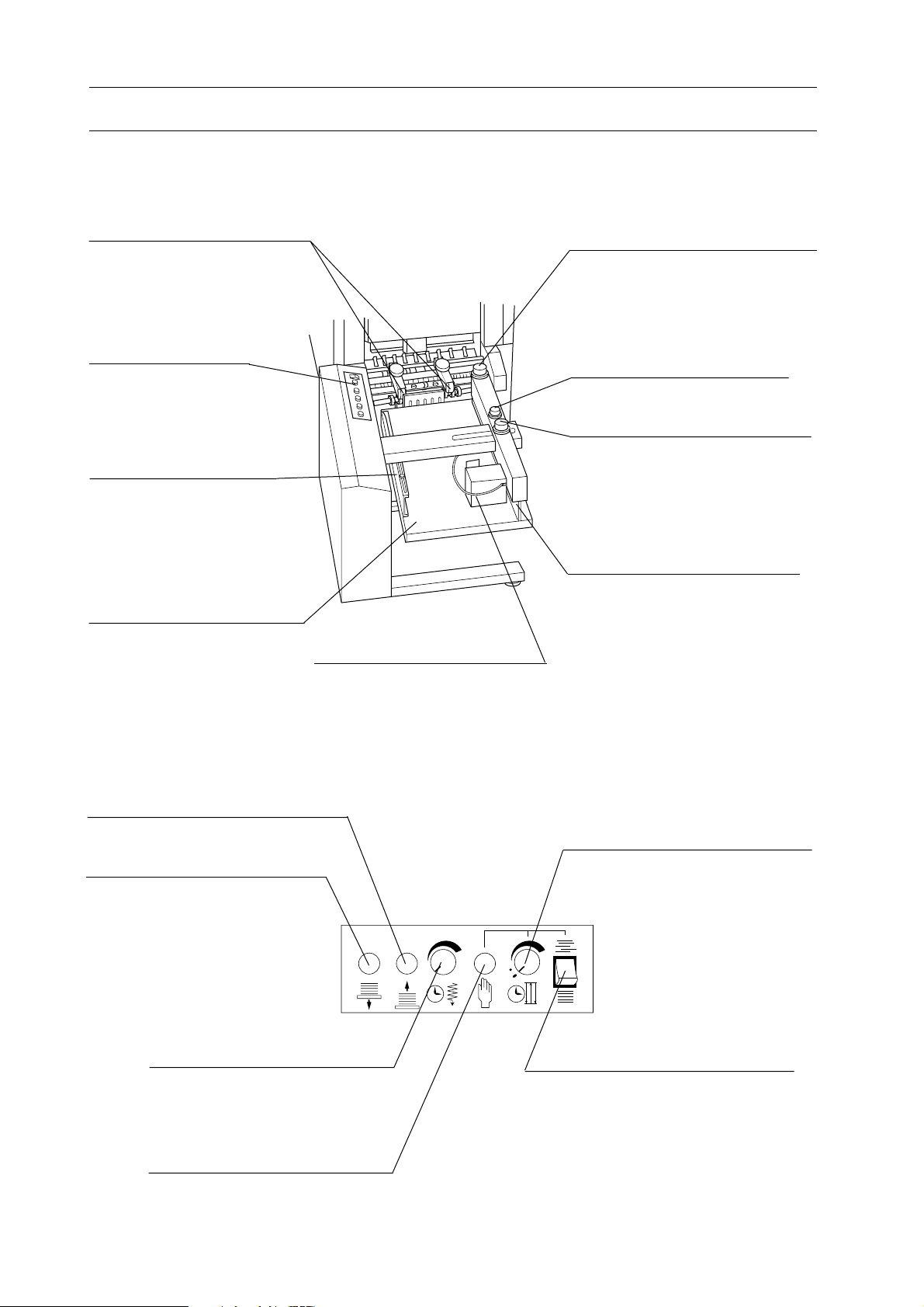
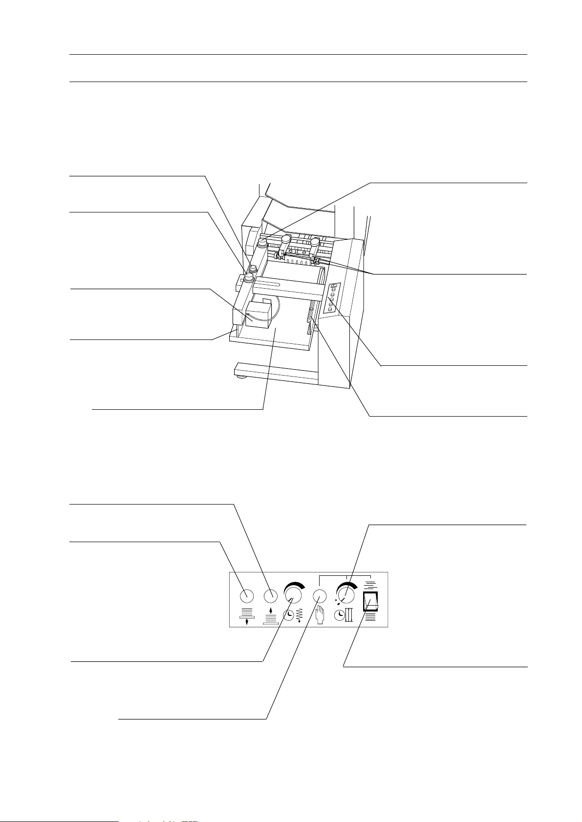
Operation Panel (a-Tower)
This panel is used to operate or setup
collator. Feed errors and troubles are
indicated on this panel.
Transport Door
Belts, which transports sheets
from each bin, are provided
inside this door. This door can
be opened or removed.
Stop Button
Operation Panel (c-Tower)
Sheets can be delivered to the right by
setting with this panel. Feed errors and
troubles are indicated on this panel.
Remote Controller
Main operation can be performed
with this remote controller.
Bin
Sheets are loaded on this bin.
Power Switch
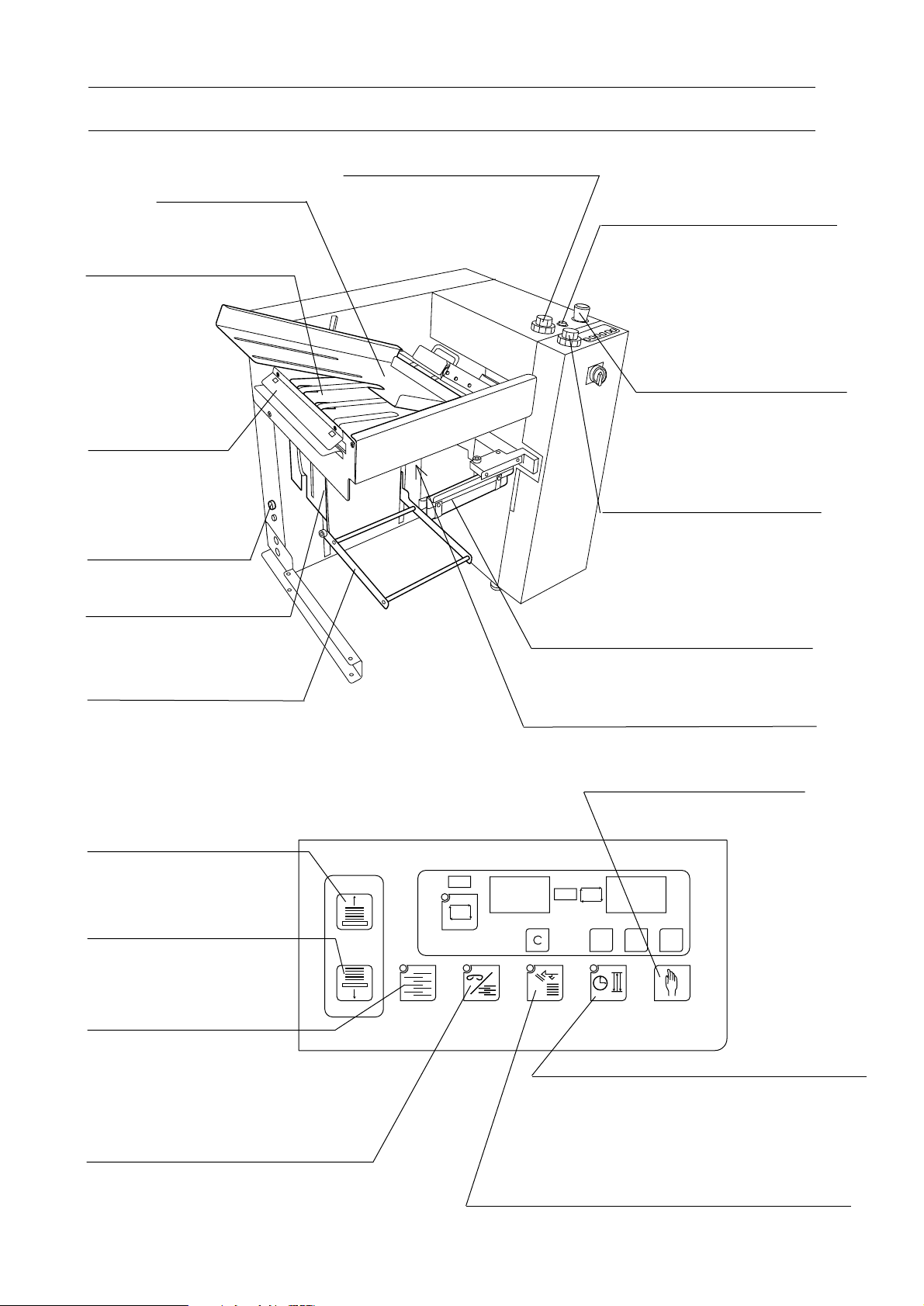
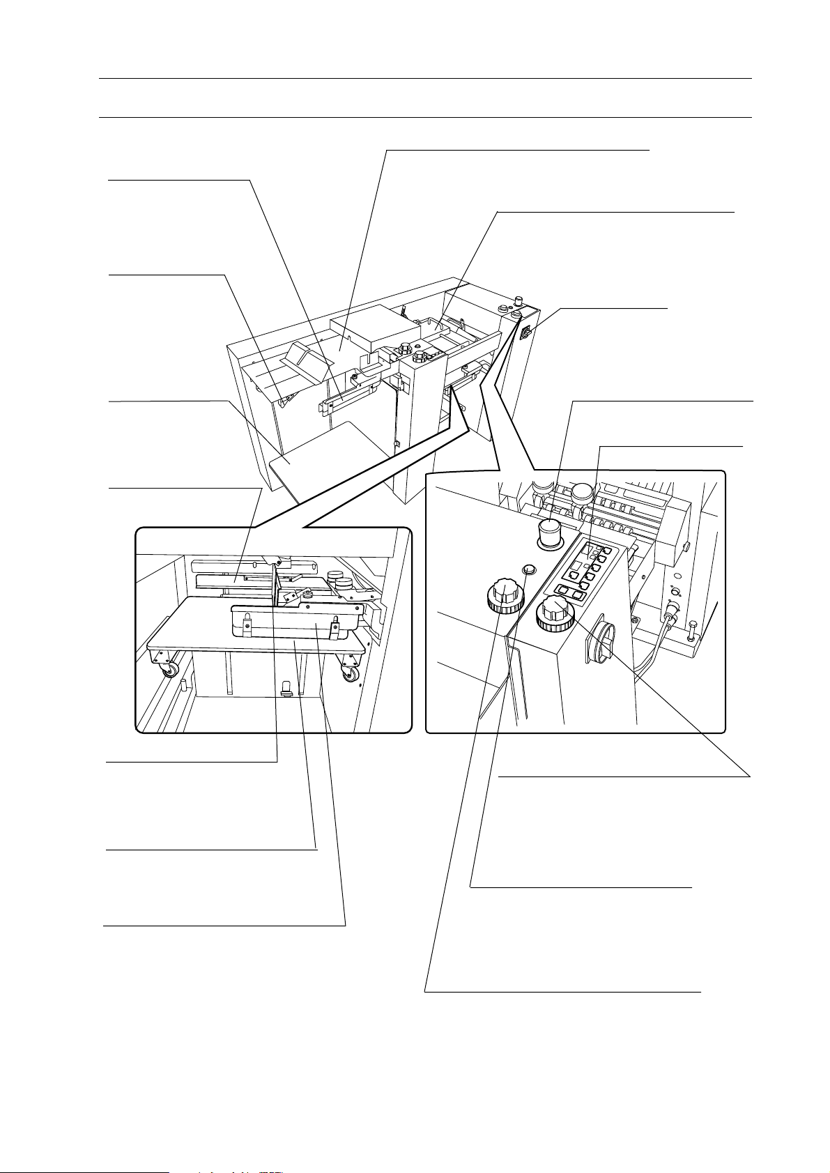
Accessories
Receiving tray or stitcher & folder
(option) can be connected as
finishing device.
Delivery Section
Sheets are transported from this section to
the accessory.
Hand Marry Unit (Option)
This unit is used to insert a sheet
on or under the collated sheets in
VAC-100. It can be attached to a tower or m-tower.
Accessories (Option)
Receiving tray can be connected
as finishing device.
Stool
This stool is used to load sheets on the upper
bin. This stool is equipped with blower.
4
Page 11
1-2 Machine Descriptions
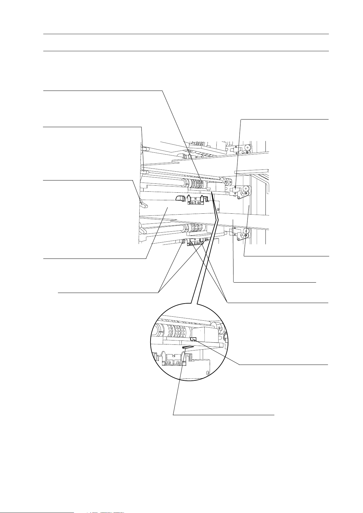
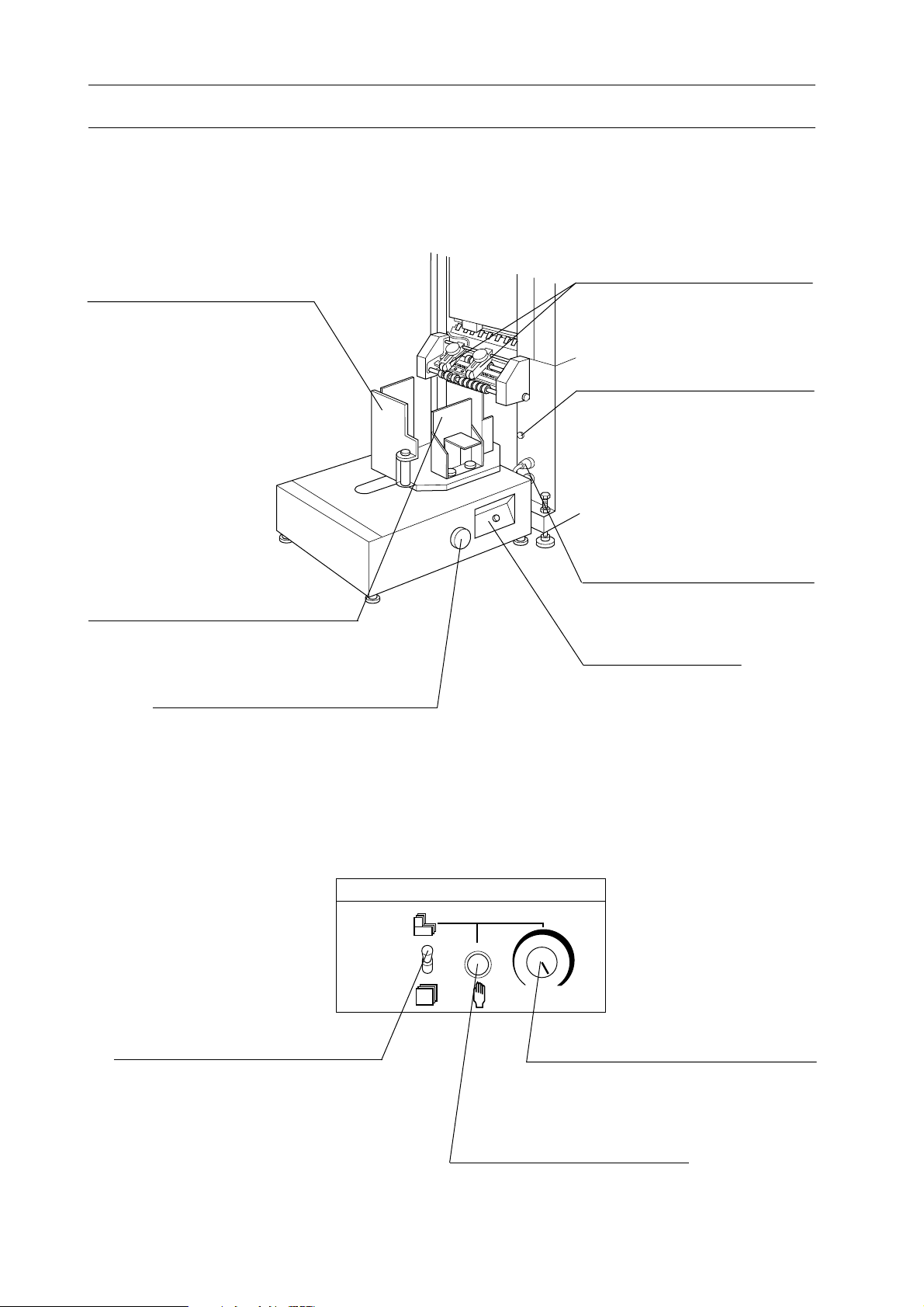
1-2-2 Feed Section
Feed Rotor
This rotor sucks and feed sheets.
1. Before You Begin
Feed Height Adjust Lever
(White)
This lever is used to adjust the
height of feed height sensor.
Separation air Adjust
Lever (Blue)
This lever is used to adjust
separation air.
Front Plate
This plate is the left register when
sheets are loaded on bin.
Blower Nozzle
Blowing air comes out from this
blower nozzle.
Feed Height Sensor
This sensor determines the
sheet feed height.
Side Guide
This guide is the rear register
when sheets are loaded on bin.
Bin
Sheets are loaded on this bin.
Double Feed Stop Plates
These plates prevent double feeding.
Separate Nose Knob
Separate Nose
This separate nose supports to
separate sheets to prevent double
feeding.
5
Page 12
1. Before You Begin
1-2 Machine Descriptions
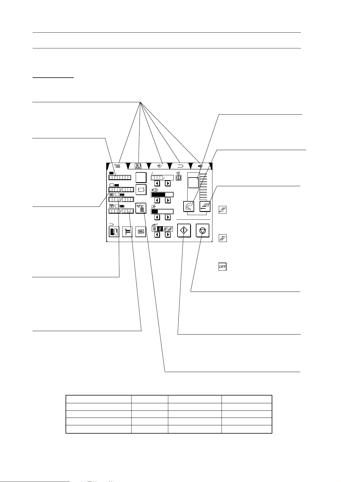
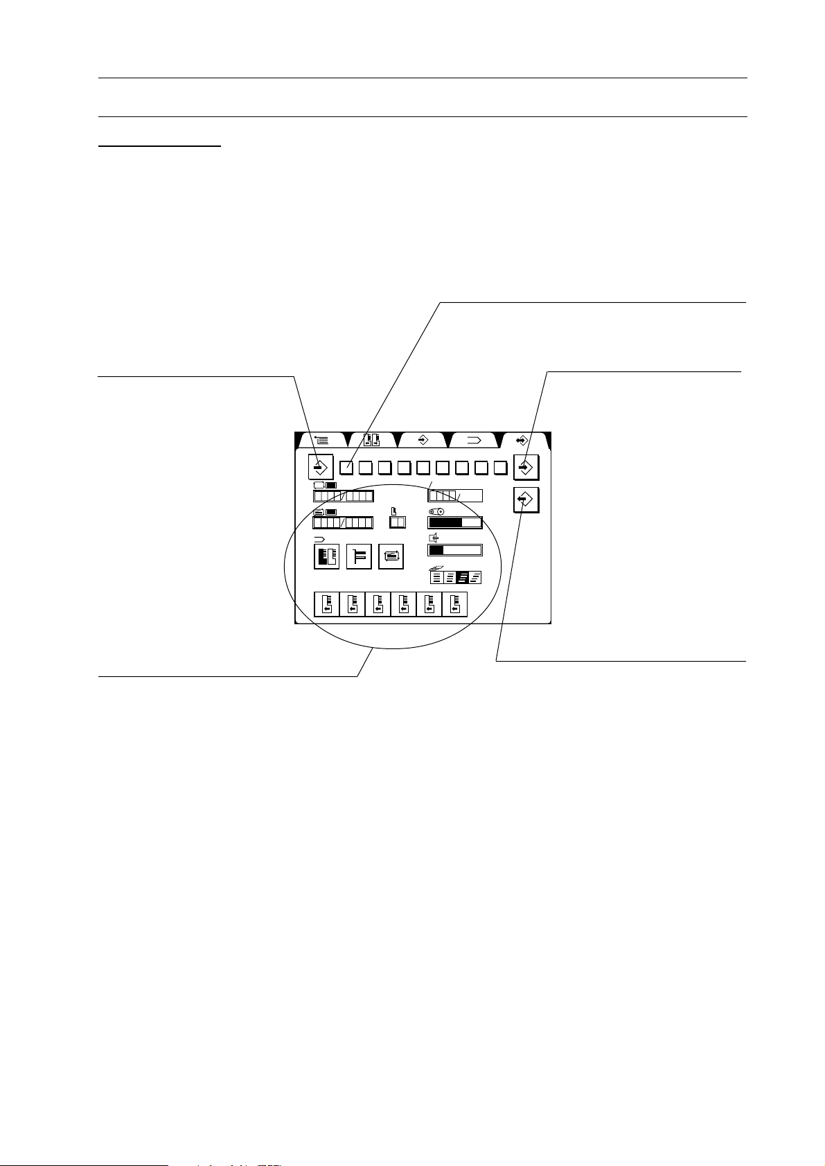
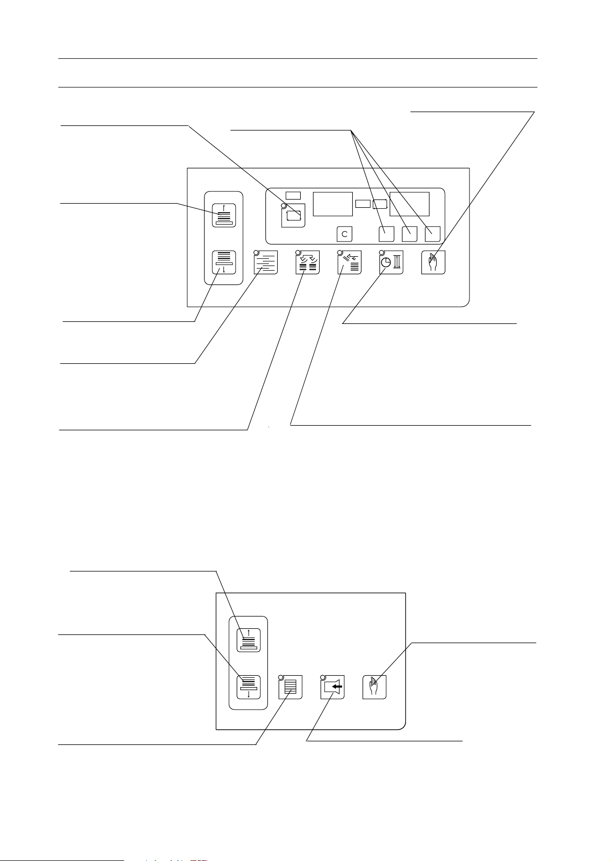
1-2-3 Operation Panel
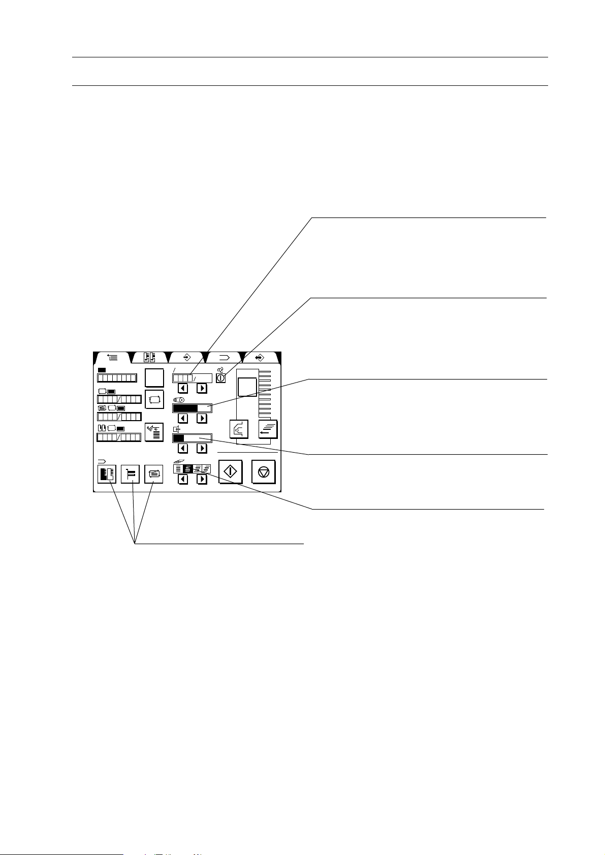
[1] Main Page
Tabs
These tabs are used to select the page
on the screen.
Total Counter
This counter counts sets of
collated sheets. This
counter can be reset with
clear button. When main
power is turned off, this
counter is reset.
Preset Counter
In case the required
number of collated sets is
input in this counter with
the right preset button, the
collation stops when the
number of collated sets
reaches the input number.
Tab Counter
This counter indicates the current
number of times of tab insert and
the preset number of tab insert.
Tab insertion must be set on the
program page.
Double Cycle Preset Counter
In case the double cycle mode is turned
on and the number of double cycle preset
is input in program screen with the
double cycle preset button, the collating
section is automatically switched over
when the number of collated sets reaches
the input number.
123
123
123
123
Error Monitor Button
This button is used to indicate
feed error.
Delivery Air ON/OFF Button
This button is used to turn on/
off delivery air.
60 min.
C
60 min.
?
Hand Marry Mode Indication
These icon indicate the selected mode on HMU-100.
: Sheet(s) from hand marry
unit is inserted under collated
sheets.
: Sheet(s) from hand marry
unit is inserted on collated
sheets.
: Hand marry unit is not
used.
Stop Button
This button is used to stop the operation.
This button must be pressed three times
to stop the collator completely and lower
bins. Refer to the chart below.
Start Button
This button is used to start the operation. The
operation will not start before sheet calibration is performed.
Feed Error Reject Function ON/OFF Button
This button is used to turn ON/OFF the function of
delivering errored sets, to the feed-error tray.
Stop Button Pressing Times
0
1
2
3
Feeding
ON
OFF
OFF
OFF
Motor and Blower
ON
ON
OFF
OFF
6
Bin
Up
UP
UP
DOWN
Page 13
1-2 Machine Descriptions
1. Before You Begin
Feed Speed Indication
Feed speed can be set with triangle buttons
below. The speed can be changed during operation.
Automatic Setup Button
This button is used only when SPF-20A is
combined. When this button is pressed, the
collator speed is adjusted automatically to match
the SPF-20A speed.
123
123
123
123
60 min.
C
60 min.
?
Belt Speed Indication
The belt which transports collated sheets can be
adjusted on three scales with triangle buttons
below.
Suction Air Indication
Suction air power can be adjusted on two scales
with triangle buttons below.
Overlap
The sheet overlap can be adjusted on four scales
Program Indication
with triangle buttons below.
These icons indicate the setup
program function.
7
Page 14
1. Before You Begin
1-2 Machine Descriptions
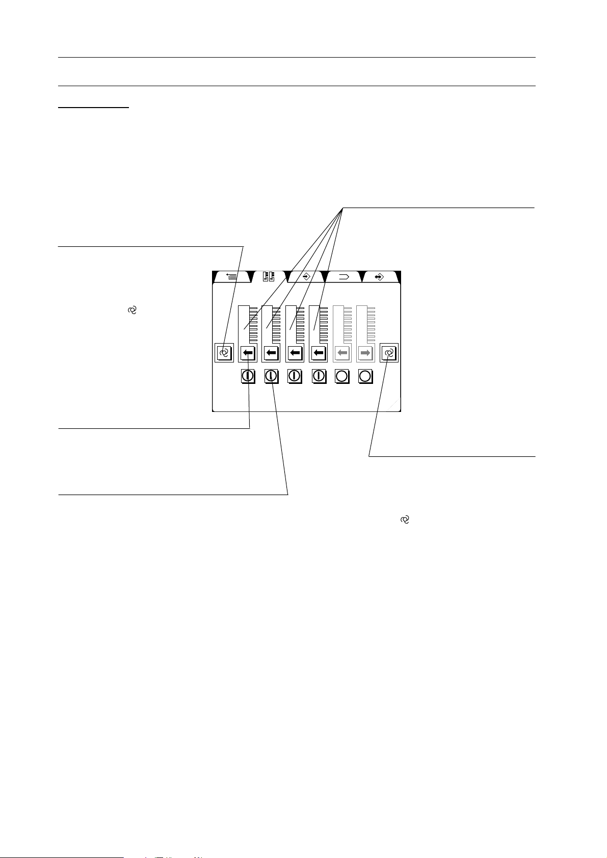
[2] Set 1 Page
Finishing Device Button
This button is used to select
the finishing device combined.
When CCR-DX is used, CCRDX icon must be selected. The
standard icon ( ) must be used
for all the other devices.
Tower Indication
The current used towers (collators) are
highlighted.
1 2 3 4 5 6
Delivery Direction Button
This button is used to select delivery
direction. The c-tower is required to
deliver collated sheets to the right.
Tower Main Power Button
The tower which is not used must be turned off.
Finishing Device Button
This button is used to select the
finishing device combined. When
CCR-DX is used, CCR-DX icon
must be selected. The standard
icon ( ) must be used for all the
other devices.
8
Page 15
1-2 Machine Descriptions
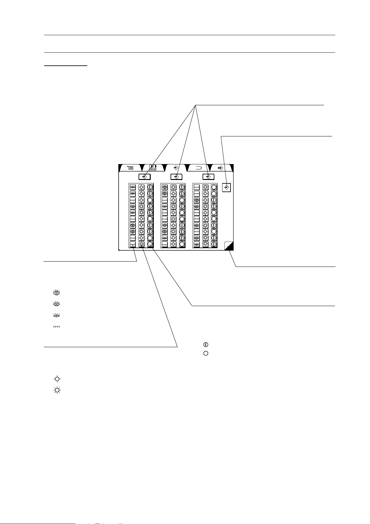
[3] Set 2 Page
123
1
2
3
4
5
6
7
8
9
10
Sensor Button
This button is used adjust feed
error sensor sensitivity on four
scales.
: High
: Middle
: Low
: Double Feed Detect OFF
Lamp Button
This button is used to adjust the light intensity
on two scales according to the sheet thickness
and print darkness.
: for Normal to Thin
1
2
3
4
5
6
7
8
9
10
1. Before You Begin
Individual Calibration Buttons
These buttons are used to calibrate the sheet
thickness in the individual tower.
All Tower Calibration Button
This button is used to calibrate the
sheet thickness in all towers.
1
2
3
4
5
6
7
8
9
10
1
2
Page UP/DOWN Button
This button is used to see the rest
of tower indication when four
towers or more are combined.
Bin Power Button
This button is used to turn on/off bin. The bin
where sheets are loaded during a sheet calibration is on. If sheets on the particular bin do not
require to be fed, the bin must be turned off.
: ON
: OFF
: for Thick or Dark Print Image
9
Page 16
1. Before You Begin
1-2 Machine Descriptions
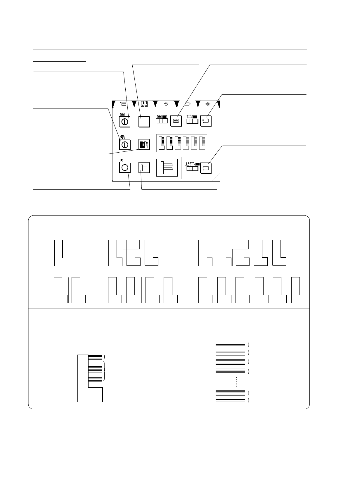
[4] Program Page
Tab Insert Button
This button is used to turn on/off
the tab insert.
Double Cycle Select
Button
This button is used to select
which section is started in
the double cycle program.
Double Cycle Button
This button is used to turn
on/off the double cycle
mode.
Dual Cover Feed Button
This button is used to turn on/off the
dual cover feed mode.
Double Cycle :
The VAC-100 system is divided into two sections. When any bin empties, the
VAC-100 immediately switches over to the second section and continues collating.
1
AB
10
1 Tower
1
A
5
6
B
10
3 Towers
Tab Sheet Button
This button is used to
select one tab sheet or
two to be used.
1
Bin Select Button
This button is used to select
which bin is started in the
dual cover feed program.
1
5
6
10
1
A
B
10
123
123
5 Towers
Preset Button
This button is used to set where tab
sheets are inserted.
Stop Button
This button is used to input
number of tab insert to stop
operation when the number of
tab insert reaches the input
number.
Double Cycle Preset Button
In case the number of double
cycle preset is input, the
123
collating section is automatically switched over when the
number of collated sets
reaches the input number.
1
10
1
A
10
1
5
6
AB
10
1
A
B
10
1
B
10
1
2 Towers
10
Dual Cover Feed : When one cover bin
1
AB
10
4 Towers
empties, the VAC-100
automatically switches over
to the other cover bin.
1
10
1
10
Cover Sheets
1
10
1
10
BBAA
6 Towers
1
10
1
A
10
1
10
1
10
1
10
1
BBAA
B
10
Tab Insert : Up to two tab sheets can be
inserted between preset collated
sets.
Tab Sheets
Collated Sets
Collated Sets
Collated Sets
Collated Sets
Collated Sets
Tab Sheets
NOTE
- Double cycle and dual cover feed programs can be operated together. The place of cover
sheets in the second section is the first two bins in the second section.
- Double cycle and tab insert programs can be operated together. The place of tab sheets in the
second section is the first bin in the second section.
10
Page 17
1-2 Machine Descriptions
[5] Memory Page
1. Before You Begin
Job No. Button
Up to nine collating setup patterns can be
stored with these buttons.
Current Setup Button
This button is used to indicate
the current setup condition of
collator.
123
123
Setup Indication
The setup condition is indicated when
current setup button or job No. button is
pressed.
Write Button
This button is used to memorize the collating setup pattern
in the selected job No.
1 2 3 4 5 6 7 8 9
hr.
hr.
Read Button
This button is used to read the memorized setup for the selected job No.
11
Page 18
1. Before You Begin
1-2 Machine Descriptions
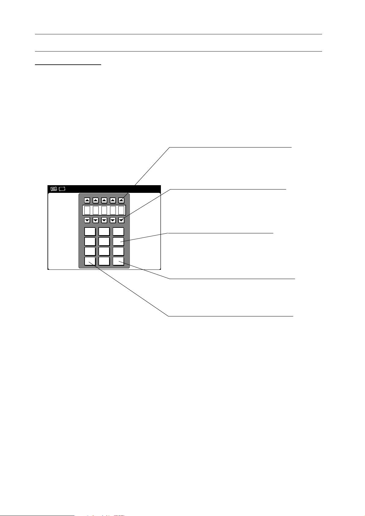
[6] Preset Input Page
The preset input page is shown by pressing preset button on the main page or program page.
UP Key
This key is used to increase the number
indicated.
DOWN Key
This key is used to decrease the number
indicated.
171
141
111
1C1
819
516
213
01E
10-number Keys
The required number can be input
with these keys.
Enter Key
This key is used to enter the number. The
page goes back after pressing this key.
Clear Key
The key is used to clear the input number.
12
Page 19
1-2 Machine Descriptions
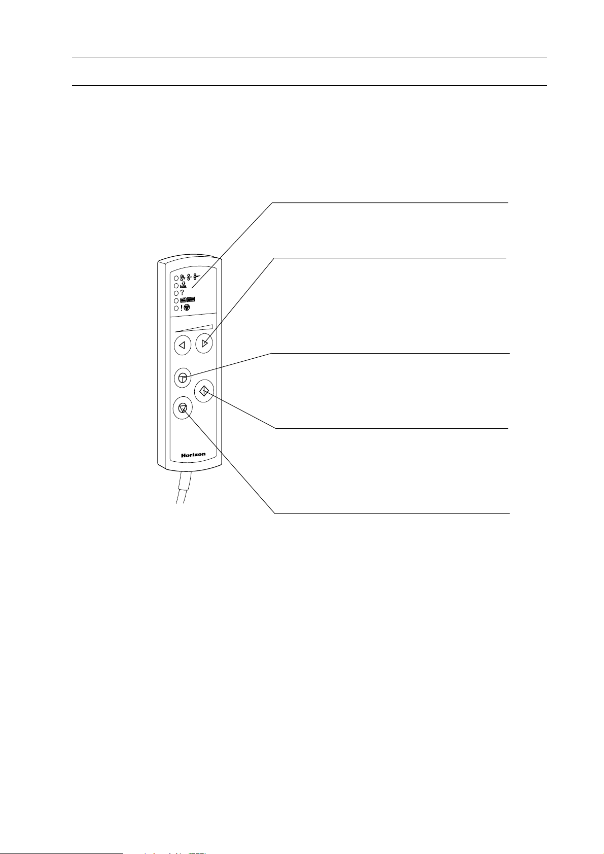
1-2-4 Remote Controller
123
1. Before You Begin
Trouble Monitor
When collating operation stops, this monitor let
the operator know the cause with lamp lighting.
Speed Button
This button is used to adjust the collating speed.
The speed can be adjusted during the operation.
This button has the same function as the one on
the main page. While this button is being
pressed, the speed is increased rapidly.
Inching Button
This button is used to inch roller and belt in the
transport and delivery sections. They can inch
during being pressed this button.
Start Button
This button is used to start the operation. The
operation cannot be started before sheet calibration is performed. This button has the same
function as the one on the main page.
Stop Button
This button is used to stop the operation. This
button has the same function as the one on the
main page. When this button is pressed with
error page shown on the screen, the screen goes
back to the main page. This function is the same
as the OK button in the error page.
13
Page 20
1. Before You Begin
1-2 Machine Descriptions
1-2-5 Receiving Tray (CCR)
Tray
Tray for A5 to A4 sheet size or
for B4 to A3 sheet size can be
selected.
Delivery Rollers
These rollers transport collated
sets to receiving tray. Weights
correct sheet skew.
Air Adjust Knob
This knob is used to adjust the
delivery air.
Stopper
This stopper must be set according to
the sheet size.
Tray Lock Knob
This knob is used to lock tray.
(Operation Panel)
Connecting Cable
This cable must be connected
to the collator connector.
Operation Panel
L
S
Off-set ON/OFF Switch
This switch is used to switch on/off
off-set.
Off-set Timing Knob
This knob is used to adjust the side
guide delay after sheets are delivered
to CCR.
Single Motion Button
Tray rotation can be actuated
with this button.
14
Page 21

1-2 Machine Descriptions
1-2-6 Receiving Tray (CCR-DX)
1. Before You Begin
Tray
Tray for A5 to A4 sheet size or for B4
to A3 sheet size can be selected.
Full Tray Sensor
(Only for Small Receiving Tray)
This sensor detects full tray.
Stopper
This stopper must be set according to
the sheet size.
Tray Lock Knob
This knob is used to lock tray.
Delivery Rollers
These rollers transport collated
sets to receiving tray. Weights
correct sheet skew.
Air Adjust Knob
This knob is used to adjust the
delivery air.
Connecting Cable
This cable must be connected
to the collator connector.
Operation Panel
(Operation Panel)
Full Tray Detection Switch
This switch is used to switch on/off
full tray detection.
Off-set ON/OFF Switch
This switch is used to switch on/off
off-set.
L
S
Off-set Timing Knob
This knob is used to adjust the side
guide delay after sheets are delivered
to CCR-DX.
Single Motion Button
Tray rotation can be actuated
with this button.
15
Page 22
1. Before You Begin
1-2 Machine Descriptions
1-2-7 Stacker (ST-20)
Delivery Rollers
These rollers transport collated
sets to receiving tray. Weights
correct sheet skew.
Operation Panel
Off-set Guide
This guide is for off-set
receiving.
Tray
Collated sets are loaded on
this tray.
Stopper Adjust Knob
This knob is used to adjust stopper according to the sheet size.
This knob can be locked with top
knob on this knob.
Stop Button
Side Guide Adjust Knob
This knob is used to adjust side
guide according to the sheet size.
This knob can be locked with top
knob on this knob.
Side Guide
This guide moves up and down
every single cycle for off-set
receiving.
Stopper
Delivered collated-sets stops by
hitting this stopper.
(Operation Panel)
Tray UP Button
This button is used to raise Tray.
Tray DOWN Button
This button is used to lower Tray.
Tray can be lowered only while
this button is being pressed.
Tray Lower Time Knob
This knob is used to adjust the
lowering length of tray every
single cycle.
Single Motion Button
Movable side guide can be
actuated with this button.
Off-set Timing Knob
This knob is used to adjust the side
guide delay after sheets are delivered to ST-20.
Off-set ON/OFF Switch
This switch is used to switch on/off
off-set.
16
Page 23
1-2 Machine Descriptions
1-2-8 Stacker (ST-20R)
1. Before You Begin
Emergency Stop Button
Side Guide Adjust Knob
This knob is used to adjust side
guide according to the sheet
size. This knob can be locked
with top knob on this knob.
Stopper
Delivered collated-sets stops
by hitting this stopper.
Side Guide
This guide moves up and down
every single cycle for off-set
receiving.
Tray
Collated sets are loaded on this tray.
Stopper Adjust Knob
This knob is used to adjust
stopper according to the sheet
size. This knob can be locked
with top knob on this knob.
Delivery Rollers
These rollers transport collated
sets to receiving tray. Weights
correct sheet skew.
Operation Panel
Off-set Guide
This guide is for off-set receiving.
(Operation Panel)
Tray UP Button
This button is used to raise tray.
Tray DOWN Button
This button is used to lower tray.
Tray can be lowered only while
this button is being pressed.
Tray Lower Time Knob
This knob is used to adjust the lowering
length of tray every single cycle.
Single Motion Button
Movable side guide can be
actuated with this button.
Off-set Timing Knob
This knob is used to adjust the side
guide delay after sheets are delivered to ST-20R.
Off-set ON/OFF Switch
This switch is used to switch on/off
off-set.
17
Page 24
1. Before You Begin
1-2 Machine Descriptions
1-2-9 Stacker (ST-40)
Feed Error Tray
All errored sets are
delivered to this tray.
Delivery Section
Removing the feed error
tray and to bring
the transport
section to a level,
collated sets are
delivered to the
stitcher.
Delivery Section
Collated sets are
delivered to the
stitcher through this
section.
Connector Section
Connect to the stitcher
Stopper
Stopper A Adjust Knob
This knob is used to adjust stopper
A according to the sheet size. The
knob can be turn-locked into
position by the lock knob.
Feed Error Lamp A
When the feed error occurs at the
collator, then the last set is delivered to the stack tray A, this lamp
will blink to alart the operator.
Stop Button
Side Guide A Adjust Knob
This knob is used to adjust side
guide According to the sheet size.
The knob can be turn-locked into
position by the rock knob.
Delivered collated sets stop
by hitting this stopper.
Folk
The stack tray is placed on this
folk. Collated sets are accumulated on the tray.
(Operation Panel)
Stack Tray UP Button
Depressing this button is
raises the stack tray.
Stack Tray Down Button
Depressing this button
lowers the stack tray.
Off-set ON/OFF Switch
This switch turns the off-set
function ON/OFF. This
button is used to raise the
stack tray.
Stack/ Stitch Select Button
Lamp ON : Stitch the collated sets at
stitcher .
Lamp OFF : Stack the collated sets at
ST-40.
Side Guide
This guide moves up and down with
every cycle for off-set receiving.
Off-set Guide
This guide is for off-set receiving.
Single Motion Button
The movable side guide can
be actuated with this button.
1 2 3
1 2 3
Off-set Delay Button
This button is used to select a delayed time for
the off-set function.
Lamp ON : Delayed time for off-set is 0.3
second
Lamp OFF : Delayed time for off-set is zero.
Feed Error Reject Function ON/OFF Button
This button is used to turn ON/OFF the function of
delivering errored sets, to the feed-error tray.
18
Page 25
1-2 Machine Descriptions
1. Before You Begin
1-2-10 Stacker (ST-60)
Side Guide B
This guide moves up
and down every cycle
for off-set receiving.
Stopper B
Delivered collated
sets stop by hitting
this stopper.
Stack Tray B
Collated sets are
accumulated on this
tray.
Off-set Guide A
This guide is for off-set
receiving.
Feed Error Tray
All errored sets are delivered to this tray.
Transport Unit
Collated sets are transported to side B
through this unit.
Power Switch
Stop Button
Operation Panel A
Stopper A
Collated sets are stopped
by hitting this stopper.
Stack Tray A
Collated sets are loaded on this
tray.
Side Guide A
This guide moves up and down with
every cycle for off-set receiving.
Side Guide A Adjust Knob
This knob is used to adjust side guide A
according to the sheet size. The knob
can be turn-locked into position by the
rock knob.
Feed Error Lamp A
When the feed error occurs at the
collator, then the last set is delivered to the stack tray A, this lamp
will blink to alart the operator.
Stopper A Adjust Knob
This Knob is used to adjust stopper A
according to the sheet size. The knob can
be turn-locked into position by the rock
knob.
19
Page 26
1. Before You Begin
1-2 Machine Descriptions
(Operation Panel A)
Counter Button
This button is used to select
the mode of the counter. For
further information, refer to 2-3.
Stack Tray UP Button
Depressing this button is
raises the stack tray.
Stack Tray Down Button
Depressing this button lowers
the stack tray.
Off-set ON/OFF Switch
This switch turns the off-set function
ON/OFF. This button is used to raise the
stack tray.
Counter Input Button
Single Motion Button
The movable side guide
can be actuated with
this button.
1 2 3
1 2 3
Off-set Delay Button
This button is used to select a delayed
time for the off-set function.
Lamp ON : Delayed time for off-set is
0.3 second
Lamp OFF : Delayed time for off-set
is zero.
Stack Mode Select Button
Lamp ON :
The collated sets are alternately routed to the
stack trays A/B one after the other.
Lamp OFF :
The collated sets are alternately routed to one of
the stack trays only. When one stack tray is full,
the collated sets are routed to the other stack tray.
(Operation Panel B)
Stack Tray Up Button
This button is used to raise the
tray.
Stack Tray Down Button
This button is used to lower the
stack tray. Stack tray can be
lowered only while this button
is being pressed.
Feed Error Reject Function ON/OFF Button
This button is used to turn ON/OFF the function of
delivering errored sets, to the feed-error tray.
ON :
When a feed error occurs at the collator, the
errored set is delivered to the feed error tray without stopping the collator. The collator will stop
after 4 consecutive errored sets are delivered to the
feed error tray.
OFF:
When a feed error occurs at the collator, collating
will stop. Errored sets will be delivered to the stack
tray.
Single Motion Button
The movable side guide
can be actuated with
this button.
Stack Tray B Height Select Button
Lamp ON : 580 mm Maximum
( 55 kg. about 700 sheets)
Lamp OFF : 580 mm Maximum
( 55 kg. about 430 sheets)
Delivery Air ON/OFF Button
This button is used to turn ON/OFF the delivery
air on the side B( left side).
Lamp ON : Delivery air is ON
Lamp OFF : Delivery air is OFF
20
Page 27
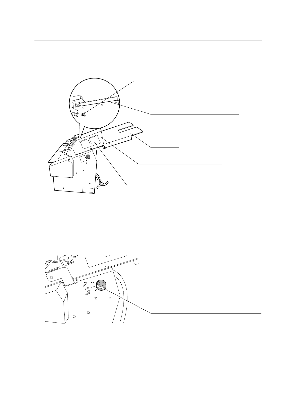
1-2 Machine Descriptions
1-2-11 Hand Marry Unit (HMU-100)
Sheet Detection Sensor
When this sensor detects a sheet, collating
operation starts.
1. Before You Begin
Sheet Registration Guide
Sheets to marry are registered with this
guide.
Sub-table
Hand Marry Table
Sheets to marry are placed on the table.
Sheet Guide
This guide is set according to sheet width.
Insert Mode Selecting Switch
This switch is used to select the mode to insert a
sheet on or under collated sheets from VAC-100
or to be off.
21
Page 28
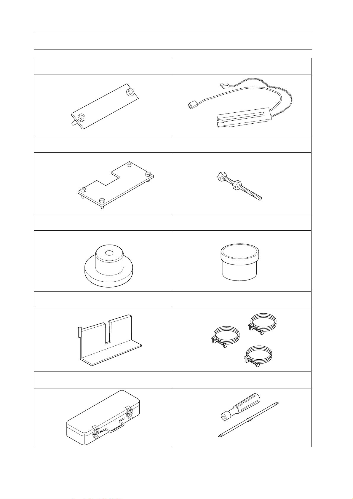
1. Before You Begin
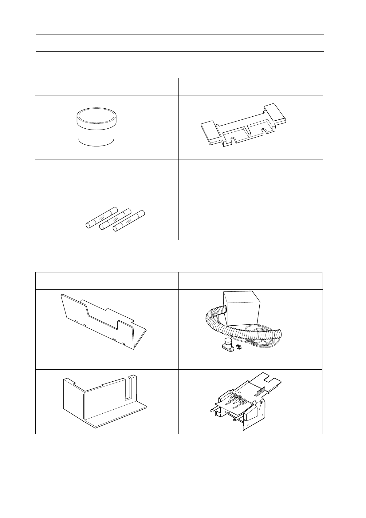
1-3 Accessories
Connecting Plate (A920112-00)
m:1pc c:1 pc
Connecting Plate (A920111-00)
m:1 pc c:1 pc
Setting Plate (M000025-01)
a: 3 pcs m: 3 pcs c: 3 pcs
Detector (A924699-00) a:1 pc
Leveling Bolt (M12-120), Nut (M12)
a: 3 pcs m:3 pcs c:3 pcs
Grease (4-001272-00)
a:1 pc c:1 pc
Sheet Guide (A924698-01)
a: 20 pcs m: 20 pcs
c: 20 pcs
Tool Box (4-003344-00)
a: 1 set c: 1 set
Hose Band
a: 3 pcs m: 3 pcs
c: 3 pcs
Reversible Screwdriver (4-005382-00)
a:1 pc c:1 pc
22
Page 29
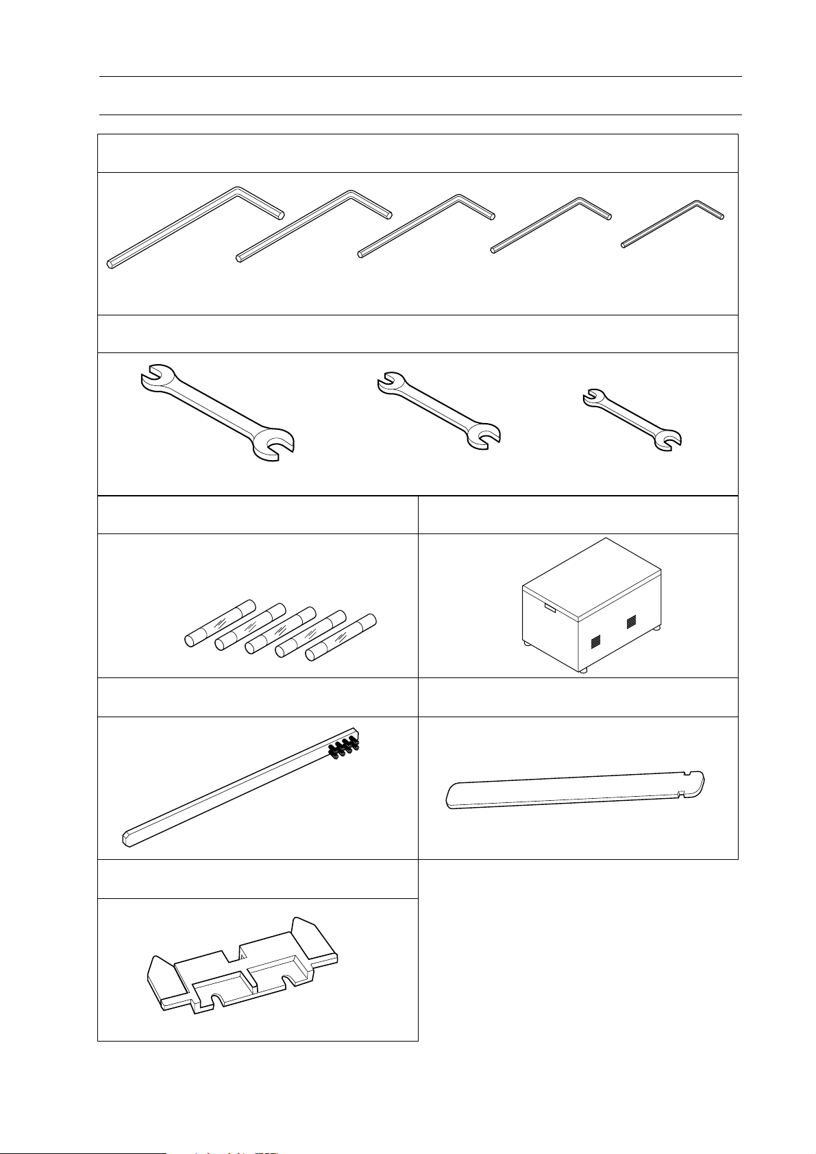
1. Before You Begin
1-3 Accessories
Allen Wrench a: 1 pc each c: 1 pc each
5 mm (4-000968-00)
4 mm (4-001439-00) 3 mm (4-001438-00)
2.5 mm (4-001437-00)
2 mm (4-001320-00)
Spanner a: 1 pc each c: 1 pc each
19 x 24 mm (4-005401-00)
Fuse
1 A (4-008911-00) : 2 pcs
2 A (4-008912-00) : 1 pcs
5 A (4-008915-00) : 3 pcs
13 x 17 mm (4-005400-00)
Blower Box
a: 3 pcs
m: 1 pcs
c: 1 pcs
8 x 10 mm (4-005397-00)
Cleaning Brush (M072641-00) a: 1 pc
Double Feed Stop Plate P (A924701-00)
10 pcs
Sheet Hold Plate (M072585-00) a: 5 pcs
23
Page 30
1. Before You Begin
1-4 Consumables and Options
Consumables
Grease (4-001272-00)
Fuse
1 A (4-008911-00)
2 A (4-008912-00)
5 A (4-008915-00)
Options
Double Feed Stop Plate (A924697-01)
Support Guide(A924629-01)
Sheet Guide (A924700-00) Hand Marry Unit (HMU-100)
Extra Air Blower (EAB-100)
24
Page 31

2. Operation Procedures
2. Operation Procedures
2-1 Power ON ................................................................................................. 26
2-2 Preparation for Operation...................................................................... 27
2-3 Collating Operation ................................................................................. 43
2-4 Feed Error Indication and Remedy ....................................................... 45
2-5 Program Collation ................................................................................... 47
2-6 Job Memory ............................................................................................. 53
2-7 Right Side Delivery.................................................................................. 54
2-8 Hand Marry ............................................................................................. 55
25
Page 32

2. Operation Procedures
123
2-1 Power ON
NOTE
- When two towers or more are used, turn on
power from the right tower.
1. Turn on power switch.
NOTE
- When turning off main power, turn off atower. Other towers can be turned off by
turning off only a-tower.
- The initial page as shown in the drawing
at right appears and 20 to 30 seconds later
the main page appears.
Power Switch
VAC-100
Now Loading....
123
123
123
123
NOTE
- When start button is pressed with inching
button pressed, the collator starts warming
up with " " indicated on the screen. Five
minutes later, warming up is stopped automatically. Press stop button when stopping
warming up.
Inching Button
60 min.
C
60 min.
?
Start Button
26
Stop Button
Page 33

2-2 Preparation for Operation
2-2-1 Tower ON/OFF and Delivery Direction Setup
1. Select Set 1 page.
2. Operation Procedures
2. Turn on tower switch of collator which is
used, turn off tower switch of collator
which is not used.
: ON
: OFF
3. When the c-tower is combined, select the
delivery direction.
NOTE
- When the c-tower is not combined, the
delivery direction is only left side.
- When the right side delivery is required,
refer to "2-7 Right Side Delivery."
1 2 3 4 5 6
Tower SwitchDelivery Direction
27
Page 34

2. Operation Procedures
2-2 Preparation for Operation
2-2-2 Collating Sheet Preparation
This section shows how to load sheets to be
collated.
123
123
123
60 min.
C
60 min.
?
1. Select the main page.
2. When bins are raised, press stop button on
the main page or remote controller to lower
bins.
3. Place sheets against side guide and front
guide.
123
Stop Button
123
Stop Button
NOTE
- When collated sheets are delivered to the
left, load sheets from the top bin in page
order. When collate sheets are delivered to
the right, load sheets from the bottom bin in
page order.
- When the number of collate pages are few,
it is efficient to load sheets from the bottom
bin.
- When two towers or more are used, it is
efficient to load sheets equally into each
tower. For example, it is more efficient to
load seven pages of sheets on both first and
second towers than to load ten pages of
sheets into the fist tower and four pages of
sheets into the second tower.
Front Plate
Collate Sheets
Side Guide
The Page Number of Collate Sheets
P1
P2
P3
P9
P10
P10
P9
P8
P2
P1
[Left Side Delivery] [Right Side Delivery]
28
Page 35

2-2 Preparation for Operation
NOTE
- Fan sheets well before loading them into
bins. Otherwise double feeding may occur. If
the sheets are bend, straighten then before
loading them into bins.
- Press firmly folded sheet edges when 4-page
signatures are collated to prevent misfeeding
or double feeding and to keep the sheet pile
height low level. Load sheets so the folded
edges touch front plate.
- The optional support guide allows collator
to collate 120 to 148 mm (4.7" to 5.8") width
sheets. (Refer to the next page.)
2. Operation Procedures
3. Set sheet guides so that they touch the
operation and right sides of sheet edges
respectively.
NOTE
- When handling acccordion-folded sheets or
NCR papers, set sheet hold plate on the right
sheet guide.
Support Guide
Sheet Guides
Sheet Hold Plate
Sheet Hold Plate
Right Sheet
Guide
Setting Direction of Accordion-folded Sheets
29
Page 36

2. Operation Procedures
2-2 Preparation for Operation
2-2-3 Small Size Sheet Setup
When small size sheets whose width is 120 to
148 mm (4.8" to 5.9") are handled, use
optional support guide.
1. Set support guide on bin where small size
sheets are loaded.
Support Guide
Sheet
Bin
2. Raise feed height sensor and move it to the
operation side.
Support Guide
Feed Height Sensor
30
Page 37

2-2 Preparation for Operation
3. Place sheets against support guide and
front guide.
2. Operation Procedures
Front Guide
Sheets
Support Guide
4. Set sheet guides so that they touch the front
and right sides of sheet edges respectively.
Sheet Guides
31
Page 38

2. Operation Procedures
2-2 Preparation for Operation
2-2-4 Feed Height Adjustment
This section shows how to adjust the feed
height.
1. Adjust feed height adjust lever (White).
UP : High
DOWN : Low
NOTE
- The standard position of feed height adjust
lever is where lever is level.
3
Feed Height Adjust Lever (White)
- When feed height adjust lever is raised, the
feeding position is raised.
- When feed height adjust lever is lowered,
the feeding position is lowered.
- After test collating, raise feed height adjust
lever when thick sheets are handled and
misfeeding occurs. Lower feed height adjust
lever when thin sheets are handled and
double feeding occurs.
- When double feeding occurs on all bins,
weaken suction air on the main page.
2-2-5 Blower Adjustment
This section shows how to adjust blower air
on each bin.
1. Adjust separation air adjust lever (Blue).
UP : Strong
DOWN : Weak
Feeding Side
3
NOTE
- Air is stronger where separation air adjust
lever is raised; weaker lowered.
- Normally, use blower with separation air
adjust lever on the top position.
- When sheets are blown up or pushed by air,
weaken air by lowering separation air adjust
lever.
Separation Air Adjust Lever
(Blue)
32
Blowers
Page 39

2-2 Preparation for Operation
2-2-6 Double Feed Stop Plate Height Adjustment
2. Operation Procedures
This section shows how to adjust the double
feed stop plate height on each bin.
1. Adjust double feed stop plate adjust lever
by moving up and down.
Lever UP : Lower plate
Lever DOWN : Raise plate
NOTE
- Double feed stop adjust lever is usually used
in the lowest position.
- After test collating, raise double feed stop
plate adjust lever to lower double feed stop
plates when misfeeding occurs.
Double Feed Stop Plates
Double Feed Stop Plate Adjust Lever
2-2-7 Separate Nose Adjustments
When double feeding occurs because of thin
sheets, use separate nose.
1. Move separate nose to the left and push out
separate nose.
NOTE
- Use separate nose only when double feeding
occurs because of thin sheets.
Separate Nose Knob
Separate Nose
33
Page 40

2. Operation Procedures
2-2 Preparation for Operation
2-2-8 Delivery Section Setup
WARNING
- Press stop button before setting up the
delivery section. Otherwise the delivery
section may hurt your hands.
[1] Bulging Nose and Delivery Roller Setup
Attach bulging nose and adjust delivery
rollers so that sheets are delivered smoothly
and jogged well.
1. Attach bulging nose so that it positioned in
the middle of the sheet.
Delivery Roller
NOTE
- Sheets are delivered with 2 cm (0.8") distance from the rear side.
2. Set delivery rollers by sliding so that
bulging nose is positioned in the middle of
delivery rollers according to the sheet size
and weight.
- Delivery rollers can be slid by raising the
end of rollers.
Bulging Nose
Delivery Rollers
Bulging Nose
Push here to lock.
Push here to remove.
2 cm
(0.8")
Thick Sheet
4-page Signature
NOTE
- When thick sheets or 4-page signature are
handled, lower bulging nose. When thin
sheets or soft sheets are handled, raise bulging nose. When large and thin sheets are
handled, use two bulging noses.
Thin Sheet
Soft Sheet
Large and Thin Sheet
34
Page 41

2-2 Preparation for Operation
[2] Weight Setup
1. Adjust the weight positions according to
the sheet thickness.
2. Operation Procedures
- Weights can be moved by turning counterclockwise.
- The standard position of weight is the
middle.
NOTE
- When sheets are delivered on the skew, the
skew can be corrected by moving weight.
- When sheets are skew in the (1) direction
shown in the drawing at right, move weights
in the A direction.
- When sheets are skew in the (2) direction
shown in the drawing at right, move weights
in the opposite direction of A.
- Weight pressure is reduced in the UP direction. When thin sheets are handled, set
weights in the UP direction. When thick
sheets are handled, you do not have to set
weight in the DOWN direction if sheets are
delivered smoothly.
Weight
A
(1)
(2)
Weight Position
UP : For thin sheets
MIDDLE : For normal sheets
DOWN : For thick sheets
A
UP
MIDDLE
DOWN
35
Page 42

2. Operation Procedures
2-2 Preparation for Operation
[3] Delivery Air Adjustment
1. Release stop button.
2. Turn on delivery air ON/OFF button.
Stop Button
123
123
123
60 min.
C
60 min.
?
3. Adjust delivery air with delivery air knob.
123
Delivery Air ON/OFF Button
Air Nozzles
NOTE
- When thin collated sets or sheets which are
difficult to be transported are handled, use
delivery air.
- Turn delivery air knob within the range of
the arrow mark shown in the drawing at
right.
Delivery Air Knob
Max.
OFF
36
Page 43

2-2 Preparation for Operation
2-2-9 Tray Unit Setup
[1] When CCR or CCR-DX Is Used
1. Insert small or large tray into shaft.
Small Tray : A5 to A4
Large Tray : B4 to A3
NOTE
- Two shafts project into tray. Insert these
shaft properly.
2. Operation Procedures
Shaft
- The sheet set direction is different depending on the tray to be used.
2. When using ST-20, insert full tray sensor
cable into main connector.
Insert Position
Small Tray Large Tray
(The arrow direction is the feed direction.)
Full Tray Sensor Cable
37
Page 44

2. Operation Procedures
2-2 Preparation for Operation
3. Place two sheets as shown with dotted lines
in the drawing at right and adjust stoppers
and off-set bar to the sheet size in number
order.
(Small Tray)
Sheet Registers
(Large Tray)
Sheet Register
Off-set Bar
3
Stopper
2
Stopper
1
Off-set Bar
- Stoppers and off-set bar can be moved by
loosening lock knobs.
NOTE
- Provide 5 to 10 mm (0.2" to 0.4") between
the sheet edge and stoppers, and between the
sheet edge and off-set bar.
Stopper
Stopper
Lock Knob
38
Page 45

2-2 Preparation for Operation
CAUTION
2. Operation Procedures
- Set receiving tray so that it does not
hit the collator delivery section when
turning receiving tray by 90˚.
4. Adjust the tray position.
- Move tray close to the collator where it
does not touch collator delivery section
and the lock tray with tray lock knob.
NOTE
- Press single motion button to turn tray and
check the distance between tray and collator.
5. Set the operation mode.
- When off-set receiving is required, turn
on off-set ON/OFF switch.
(CCR)
Stopper
Collator
Tray Lock Knob
Off-set Timing Knob
- Set off-set timing knob to the required
position.
- When using small tray of CCR-DX, turn
on full tray detection switch.
Off-set ON/OFF Switch
Single Motion Button
(CCR-DX)
Full Tray Detection Switch
L
S
L
S
Off-set Timing Knob
39
Page 46

2. Operation Procedures
2-2 Preparation for Operation
[2] When ST-20/ST-20R Is Used
WARNING
- Press stop button before setting stoppers and guides on tray. Otherwise
personal injury may result.
(Off-set Receiving)
1. Press tray UP button to raise tray.
2. Press stop button.
3. Place a sheet as shown with dotted lines in
the drawing at right and then adjust side
guide and stopper in number order.
NOTE
- Provide 5 mm (0.2") gap between the sheet
edge and stopper, and between the sheet edge
and side guide.
- When the sheet size is B4 or more, attach
guide strip.
4. Attach support stopper on the same posi-
tion as stopper's.
Off-set Guide
Support Stopper
Stopper
Side Guide
5 mm
(0.2")
Side Guide Adjust Knob
Off-set Timing KnobTray UP Button
Guide Strip
Sheet Registers
5 mm
(0.2")
Sheet
1 2
Stopper Adjust Knob
5. Set the operation mode.
- Turn on off-set ON/OFF switch. (" "
position)
-Set off-set timing with off-set timing knob.
Turning knob clockwise makes off-set
time longer.
- Set tray lower time with tray lower time
knob according to the collated set thickness. Tray lowers by turning knob clockwise.
(Straight Receiving)
CAUTION
- Turn off off-set ON/OFF switch
" position) when straight receiving
("
is required.
1. Attach straight receiving guides and lock
them with lock knob.
Tray Lower Time Knob
Lock Knob
Off-set Timing Knob
Off-set ON/OFF Switch
Straight Receiving Guides
2. Adjust stoppers and side guide in the same
procedure as the step 3 above.
40
Page 47

2-2 Preparation for Operation
2-2-10 Setup in Main Page
This section shows how to set the feeding
condition in main page.
1. Set the belt speed. (3 scales)
2. Operation Procedures
[Main Picture]
NOTE
-The belt speed can be adjusted on three
scales. Normally, set the middle speed. After
test collating, set the fast speed if sheets are
fed smoothly. On the contrary, if misfeeding
occurs, set the slow speed.
2. Set the feed speed.
NOTE
- The feed speed changes depending on the
belt speed and overlap used.
- The feed speed can be adjusted during the
operation.
- When SPF-20A is combined, the feed speed
is automatically adjusted by pressing automatic set up button.
3. Set air strength. (2 scales)
NOTE
- Air strength can be adjusted on two scales.
Normally, select strong. When double feeding
occurs because of thin sheets, select weak to
decrease the sucking force of the rotor.
123
123
123
123
60 min.
C
60 min.
?
4. Set overlap. (4 scales)
NOTE
- Overlap can be adjusted on four scales.
- After the actual collation, adjust the overlap
for good delivery to the receiving tray or
stitcher & folder.
5. When using total counter, press clear key
to reset the counter.
6. When using preset counter, press the
required number with 10-number keys, and
then press enter key to input the number.
To clear the input number, press clear key.
After pressing enter key, the main page
appears.
[Preset Input Picture]
Clear Key
41
17181
14151
11121
1C101
9
6
3
E
Enter Key
Page 48

2. Operation Procedures
2-2 Preparation for Operation
2-2-11 Hand Marry Unit Setup (HMU-100: Option)
When using hand marry unit, set the sheet
guide and select the mode to insert a sheet on
or under collated sheets.
1. Select the mode with the insert mode
selecting switch.
: A sheet from hand marry unit is inserted on
collated sheets.
: Hand marry function is not used.
: A sheet from hand marry unit is inserted
under collated sheets.
- The selected mode on HMU-100 is indicated
by the icon on main page of VAC operation
panel.
2. Place sheets on hand marry table register-
ing with the sheet registration guide and set
the sheet guide according to sheet width.
Insert Mode Selecting Switch
123
123
123
123
60 min.
C
60 min.
?
(Main Page Of VAC Operation Panel)
Place the sheets registering with this guide
42
Sheet Guide
Page 49

2-3 Collating Operation
2-3-1 Sheet Thickness Calibration
Before actual collating operation, sheets
thickness must be calibrated and memorized.
Adjust sensor and/or lamp on each bin on the
Set 2 page with sheet calibration.
1. Select Set 2 page.
NOTE
- When each bin power is off, sheets are not
fed even if sheets are loaded on the bin.
2. Set senor to middle sensitivity and lamp to
normal.
NOTE
- The initial setting of sensor is middle sensitivity and lamp, normal.
- When sensor detects double feeding without
double feeding during the actual operating,
set sensor to low sensitivity. After that, sensor
still detects double feeding occurs, turn off
sensor. When sensor detects misfeeding
without misfeeding, set sensor to low sensitivity.
- When sensor is turn off, sensor detects only
misfeeding, not double feeding.
- Normally, set lamp to normal. When sensor
senses thick image on sheets or detects misfeeding without misfeeding, set lamp to
bright.
2. Operation Procedures
All Tower Calibration Button
Individual Calibration Buttons
123
1
2
3
4
5
6
7
8
9
10
1
2
3
4
5
6
7
8
9
10
1
2
3
4
5
6
7
8
9
10
Sensor
: High Sensitivity
: Middle Sensitivity
: Low Sensitivity
: Double Sheet Detection OFF
Lamp
: Normal
: Bright
1
2
3. Press all tower calibration button.
- Each bin on all used towers feeds one
sheet.
NOTE
- When individual calibration button is
pressed, sheets only on the tower whose
button is pressed are fed once.
4. Check the number of collated sheets is
correct.
NOTE
- When the number of collated sheets is not
correct, press individual calibration button of
the tower which has a problem.
- When double feeding is monitored during a
sheet calibration, set lamp to bright and
check again.
- When double feeding of a collated set is
missed on receiving tray, misfeeding will be
detected during the actual operation.
Bin
: ON
: OFF
43
Page 50

2. Operation Procedures
2-3 Collating Operation
2-3-2 Collating Operation
This section shows how to operate the collator.
1. Select the main page.
2. Press start button either on the main page
or on remote controller.
NOTE
- The operation will not start before sheet
thickness calibration is completed. (Refer to
"2-3-1 Sheet Thickness Calibration.")
- When using the hand marry unit, refer to
"2-8 Hand Marry"
3. Press stop button either on the main page
or on remote controller.
NOTE
- When stop button is pressed during operation, only feeding is stopped, not motor and
blower. When stop button is pressed again,
motor and blower are stopped, but bins are
not lowered. When stop button is pressed
again, bins are lowered.
123
123
123
123
60 min.
C
Start Button
123
60 min.
?
Stop Button
Start Button
Stop Button Pressing Times
0
1
2
3
Feeding
ON
OFF
OFF
OFF
Motor and Blower
ON
ON
OFF
OFF
Stop Button
Bin
Up
UP
UP
DOWN
44
Page 51

2-4 Feed Error Indication and Remedy
: Double Feed
: Jam
: Misfeed
Feed Error Mark
123
When jam, misfeeding and double feeding
occur, the collator delivers the collated sets
and then stops with errors indicated on the
screen and remote controller.
2. Operation Procedures
1. When the operation is stopped because of
feeding errors, the numbers 1 and 3 on
the right side on the screen mean that top
collated sets and 3rd collated sets from the
top on receiving tray have feed error. The
feed error icons indicate all errors when the
collator is stopped.
NOTE
- The feed error can be indicated on up to the
eighth collated set.
2. Press the number 1 button on the right
side. Check the top collated set delivered
on receiving tray.
- Jam occurred on the second bin of the
second tower.
- Double feeding occurred on the first bin
of the fourth tower.
112 3
2
3
4
5
6
7
8
9
10
1
1
2
3
4
5
6
7
8
9
10
2 3
5 6
4
1
2
3
4
5
6
7
8
9
10
4
1
2
3
4
5
6
7
8
9
10
5 6
OK
1
2
1
3
4
3
5
6
7
8
9
10
OK
1
2
1
3
4
3
5
6
7
8
9
10
NOTE
- Jam may be monitored though sheets are
ejected. This is because feed timing is delayed. Check that sheets are not jammed.
Inching Button
When jammed, press inching button to transport the sheet, open transport door and then
remove the sheet.
Transport Door
45
Page 52

2. Operation Procedures
2-4 Feed Error Indication and Remedy
3. Press the number 3 button on the right
side. Check the third collated set from the
top on receiving tray.
- Double feeding occurred on the first bin
of the sixth tower.
- Misfeeding occurred on the third bin of
the sixth tower.
NOTE
- When sheet feed timing is delayed, the
operation stops immediately with all tower
numbers and jam marks indicated on screen
as shown in the drawing at right. When this
occurs, eject the jammed sheet by pressing
inching button and check from the top to the
fifth collated sets on receiving tray.
112 3
2
3
4
5
6
7
8
9
10
112 3
2
3
4
5
6
7
8
9
10
5 6
4
1
2
3
4
5
6
7
8
9
10
4
1
2
3
4
5
6
7
8
9
10
5 6
OK
1
2
1
3
4
3
5
6
7
8
9
10
OK
1
2
1
3
2
4
3
5
4
6
5
7
6
8
7
9
8
10
4. Press
button or stop button on
OK
remote controller to go back to the main
page.
NOTE
- When feed error monitor is required to see
again, press error monitor button on the
main page.
123
123
123
123
60 min.
C
60 min.
?
46
Page 53

2-5 Program Collation
A
B
AB
AB
BBAA
A
B
1
5
6
10
1
10
1
10
1
10
1
5
6
10
1
10
AB
A
B
1
10
A
1
10
1
5
6
10
1
10
B
1
10
1
10
1
10
1
10
1
10
BBAA
1
10
A
1
10
1
10
1
10
1
10
B
1
10
2-5-1 Double Cycle
The VAC-100 system is divided into two
sections. When any bin empties, the VAC-100
immediately switches over to the second
section and continues collating.
2. Operation Procedures
1 Tower
2 Towers
3 Towers
4 Towers
1. Load sheets on bins so that the first section
A and the second section B in the drawing
above have the same contents.
NOTE
- When using only 1 tower and 1 collated sets
use four bins, load sheets from the bins 1 to
4, and then load the same content sheets from
the bins 6 to 9, from the bins 7 to 10, or the
bins 6, 8 to 10.
- On the tower divided half of 1 tower, 3 or 5
towers, load sheets by 40 mm (1.5") height or
less because separation air may curl loaded
sheets.
5 Towers
6 Towers
2. Prepare for collating referring to the "2-2
Preparation for Collation."
3. Select program page.
4. Turn on double cycle button.
5. Select which section is started first with
double cycle select button.
NOTE
- When sheets are delivered to the right, the A
and B sections are reversed.
Double Cycle Select Button
Double Cycle Button
1
47
123
123
123
Page 54

2. Operation Procedures
2-5 Program Collation
6. Press all tower calibration button on the Set
2 page referring to the "2-3-1 Sheet Thickness Calibration."
Individual Calibration Buttons
All Tower Calibration Button
- All sheets on bins of all towers are collated once.
7. Select the main page and press start button.
- When any bin empties in the first section,
the collator switches over to the second
section automatically and continues
collating.
NOTE
- Add sheets on bins which are paused.
- Double cycle and dual cover feed programs
can be operated together. Refer to "2-5-2
Dual Cover Feed" and "2-5-3 Tab Insert."
123
1
2
3
4
5
6
7
8
9
10
123
123
123
123
1
2
3
4
5
6
7
8
9
10
60 min.
C
60 min.
Start Button
1
2
3
4
5
6
7
8
9
10
Stop Button
1
2
?
- When the collating speed is too fast or some
bin empties in one section, misfeeding may be
indicated on screen. In this case, remove the
top collated set on receiving tray and press
start button. The collator switches over to the
other section automatically to start collating
operation.
123
Start Button
Stop Button
48
Page 55

2-5 Program Collation
2-5-2 Dual Cover Feed
Normally, cover sheets are thicker than
inside sheets, so the bin loading cover sheets
empties earlier than other bins. This dual
cover feed program enables operation to
continue without interrupting by switching
over to the other bin loading cover sheets
when one bin loading cover sheets empties.
1. Load cover sheets into the top two bins,
and inside sheets into the rest bins. (Refer
to "2-2 Preparation for Collation.")
NOTE
- For example, when using the third to ninth
bins, load cover sheets into the third and
fourth bins.
2. Operation Procedures
Cover Sheets
Inside Sheets
2. Select the program page.
3. Turn on dual cover feed button.
4. Select which bin loading cover sheets is
used first with bin select button.
5. Press all tower calibration button on the Set
2 page referring to "2-3-1 Sheet Thickness
Calibration" and check the collating condition.
- All sheets of all towers are collated once.
Cover sheets on both bins are also collated.
123
1
Dual Cover Feed Button
Bin Select Button
All Tower Calibration Button
Individual Calibration Buttons
123
1
2
3
4
5
6
7
8
9
10
1
2
3
4
5
6
7
8
9
10
1
2
3
4
5
6
7
8
9
10
123
123
1
2
49
Page 56

2. Operation Procedures
2-5 Program Collation
6. Select the main page and press start button.
- When one bin loading cover sheets empties, the collator switches over to the other
bin automatically.
123
123
123
123
60 min.
C
60 min.
?
NOTE
- Dual cover feed and double cycle programs
can be operated together. The position of
cover sheet loading in the second section is
the top two bins in the second section.
- Dual cover feed and tab insert programs can
not be operated together.
- When the collating speed is too fast or some
bin empties in one section, misfeeding may be
indicated on screen. In this case, remove the
top collated set on receiving tray and press
start button. The collator switches over to the
other section automatically to start collating
operation.
10
Start Button
123
Stop Button
Start Button
Stop Button
1
Cover Sheets
(The first and second bins)
5
6
Cover Sheets
(The sixth and seventh bins)
50
Page 57

2-5 Program Collation
2-5-3 Tab Insert
2. Operation Procedures
Up to two tab sheets can be inserted between
collated sets preset.
1. When one tab sheet is inserted, load the tab
sheets into the top bin. When two tab
sheets are inserted, load the tab sheets into
the top two bins. And then load inside
sheets into the rest bins. (Refer to "2-2
Preparation for Collation.")
2. Select the program page.
3. Turn on tab insert button.
4. Select one or two with tab sheet button.
Tab Insert Button
Tab Sheet Button
1
Tab Sheets
Collated Sets
Collated Sets
Collated Sets
Collated Sets
Tab Sheets
Preset Button
123
Preset Stop Button
123
123
5. Input the required number of collated sets
between tab sheets with preset button.
6. When the operation is required to stop after
any tab inserting times, input the required
number of inserting times with preset stop
button.
7. Press all tower calibration button on the Set
2 page referring to "2-3-1 Sheet Thickness
Calibration" and check the collating condition.
- All sheets of all towers are collated once.
Cover sheets on both bins are also collated.
17181
14151
11121
1C101
9
6
3
E
All Tower Calibration Button
Individual Calibration Buttons
123
1
2
3
4
5
6
7
8
9
10
1
2
3
4
5
6
7
8
9
10
1
2
3
4
5
6
7
8
9
10
1
2
51
Page 58

2. Operation Procedures
2-5 Program Collation
8. Select the main page and press start button.
- Tab sheets are inserted between the preset
number of collated sets and operation is
stopped with preset number of tab inserting times.
NOTE
- When preset stop is used, the set number is
indicated in tab counter on the main page.
123
123
123
123
Tab Counter
C
123
60 min.
60 min.
Start Button
?
Stop Button
NOTE
- Tab insert and double cycle programs can
be operated together. The position of tab
sheet loading in the second section is the top
bin or two in the second section.
- Tab insert and dual cover feed programs
can not be operated together.
10
Start Button
Stop Button
1
Tab Sheets
(The first and second bins)
5
6
Tab Sheets
(The sixth and seventh bins)
52
Page 59

2-6 Job Memory
The collation set up can be memorized and
used in the future operation. Up to nine jobs
can be memorized.
NOTE
- The following setups can be memorized.
Feed Speed
Belt Speed
Air Strength
Overlap
Using Bin Number
Preset Counter
Type of Program Collation
Delivery Direction
Sensor Lamp Adjustment
2. Operation Procedures
- The job memory function is not available
on c-tower.
1. Select the main page.
2. When current setup button is pressed, the
current collator setup is indicated. When
job No. button is pressed, the memorized
setup is indicated.
3. When the current set up is required to
memorize, press job No. button and then
write button.
- The former input set up is cleared and the
current set up is memorized.
4. When the memorized set up is required to
read, press job No. button and check the set
up indication. And then press read button.
Current Setup Button
Job No. Button
1 2 3 4 5 6 7 8 9
123
123
Write Button
hr.
hr.
Read Button
- The set up of the collator is changed to
the memorized setup.
53
Page 60

2. Operation Procedures
2-7 Right Side Delivery
When c-tower is combined, collated sets can
be delivered to the right.
1. Select the Set 1 page on a-tower operation
panel on the left end.
2. Select the delivery direction.
NOTE
- The delivery direction can be set as shown
in the drawing at right. While 1 and 2 towers
are delivering on the left side, 3 and 4 towers
can perform the right side delivery.
1 2 3 4 5 6
- The delivery direction can not be set on ctower.
3. To change the delivery direction, select
another page to determine the delivery
direction.
4. Set up the collator referring to "2-2 Prepa-
ration for Collation"
NOTE
- To deliver collated sets to the right, load
sheets from the bottom in order with the front
side down as shown in the drawing at right.
Collated sheets are delivered upside down.
5. Set the collating condition and start/stop
operation on c-tower.
Delivery Direction Button
Page Order of Collated Sets
P20
P19
P18
P12
P11
[Right Side Delivery]
P10
P9
P8
P2
P1
NOTE
- The right side delivery operation can be
performed only on c-tower.
- Program collations are available in the
right side delivery operation.
54
Page 61

2-8 Hand Marry
This section shows how to hand marry a
sheet on or under collated sheet with hand
marry unit.
1. Select the main page.
2. Press start button either on the main page
or on remote controller.
NOTE
- The operation will not start before sheet
thickness calibration is completed. (Refer to
"2-3-1 Sheet Thickness Calibration.")
3. Place sheets on the hand marry unit.
-when the senser detects a sheet, collating
operation starts.
NOTE
2. Operation Procedures
123
123
123
123
60 min.
C
Start Button
60 min.
?
Stop Button
- When selecting the mode
with insert
mode selecting switch, sheets on hand marry
table are deliveried in a second after placing
sheets on the table and then the collating
operation starts.
When selecting the mode with insert mode
selecting switch, the collating operation starts
in a second after placing sheets on the table
and then sheet on hand marry table is
deliveried.
-Even changing the mode with the insert
mode selecting switch after pressing start
buttom in VAC-100, the mode does not
change.When changing the mode, press stop
buttom to stop collating and change the mode
with the insert mode selecting switch.
ATTENTION
- When sheet from hand marry unit is
jammed on the mode , only collated sheets
123
Start Button
Stop Button
Put the sheets registering
with this guide
in VAC are deliveried to the finishing device.
The error is not indicated on the panel in
VAC-100.
- When sheet from hand marry unit is
jammed on the mode , after the collated
sheets in VAC-100 are deliveried, the rollers
continue to rotate and the finishing device
waits the sheet to be deliveried from hand
marry unit. In this case, press stop buttom to
stop collating.When a sheet from the hand
marry unit is jammed, refer to "3-6 Sheet
from hand marry unit is jammed"
Sheet Guide
55
Page 62

2. Operation Procedures
2-8 Hand Marry
4. Press stop button either on the main page
or on remote controller.
NOTE
- When stop button is pressed during operation, only feeding is stopped, not motor and
blower. When stop button is pressed again,
motor and blower are stopped, but bins are
not lowered. When stop button is pressed
again, bins are lowered.
Stop Button Pressing Times
0
1
2
3
Feeding
ON
OFF
OFF
OFF
Motor and Blower
ON
ON
OFF
OFF
Bin
Up
UP
UP
DOWN
56
Page 63

3. Troubleshooting
3. Troubleshooting
3-1 Error Indication and Remedy ................................................................ 58
3-2 When Misfeeding Occurs........................................................................ 59
3-3 When Double Feeding Occurs................................................................ 59
3-4 Sheets Are Fed on the Skew ................................................................... 60
3-5 Paper Jam in Transport Conveyor ........................................................ 60
3-6 Sheet from Hand Marry Unit Is Jammed ............................................. 61
3-7 Collating Operation Does Not Start Even If Pressing Start Button... 61
3-8 Fuse and Breaker Check ......................................................................... 62
3-9 Pump Does Not Work ............................................................................. 65
57
Page 64

3. Troubleshooting
101
3-1 Error Indication and Remedy
When some error occurs during collation, the
cause is indicated on operation panel.
Feed Error
Double feeding, misfeeding or jam occurred.
Refer to "2-4 Feed Error Indication and Remedy."
Bin Empty
Bin is empty. Add sheets.
Operation Error
?
Operation error occurs;
- Start button is pressed before sheet thickness calibration.
- The number of used bins are different
between the fist and second sections in
double cycle.
- Bin power is off.
Operate collator in the proper procedures.
Door Open
Transport door is open. Close the door.
?
1
?2?3?4?5?6?
OK
System Error Code
(Refer to the table
below for detail)
Accessory Error
Some error happened in the finishing device.
Remove the cause from the accessory. When
stop button of the finishing device is being
pressed, this mark is indicated. And also, this
mark is indicated when transport belt of
stitcher & folder is not rotating.
Emergency Stop
Emergency stop button is being pressed.
Release the button.
Jam in the Delivery Section
Sheets are jammed in the delivery section.
Remove the jammed sheets.
System Error
System error happened. Turn off main power
and five seconds later turn on power. If the
system error X51 or X52 (X:Number of tower
where the system error happened) happened,
press the "OK" Button on the operation panel
or the Stop Button on the remote controller to
reset.
System Error Code Table
Codes
Communication Error with Operation Panel
X01
X02
Communication Error with Operation Panel
Internal Error
X07
X25
Control Software Error
X50
Inverter Error
X51
Delivery Sensor Error
X52
Pulse Error
X87
Communication Error between Towers
X88
Communication Error between Towers
X89
Communication Error between Towers
Internal Error
X99
Causes
Turn off the power. Wait 5 sec. or more and turn on the power.
Turn off the power. Wait 5 sec. or more and turn on the power.
Turn off the power. Wait 5 sec. or more and turn on the power. See how the condition improves for some time.
Turn off the power. Wait 5 sec. or more and turn on the power.
Turn off the power. Wait 5 sec. or more and turn on the power.
Check the paper dust on the delivery sensor or the sensor position.
Check the loading of the pulse encorder or the paper dust on the encorder.
Check the communication cable between towers and the dip switch on the P.C.B..
Turn off the power. Wait 5 sec. or more and turn on the power.
Turn off the power. Wait 5 sec. or more and turn on the power.
Turn off the power. Wait 5 sec. or more and turn on the power.
Full Tray
Receiving tray is full. Unload collated sets
from tray.
NOTE
- When the stacker ST-20R is connected to
the single VAC-100a and the collated sets are
delivered to the left, this full tray indication
will appear. When the stacker ST-20 is connected to the single VAC-100a and the collated sets are also delivered to the left, this
full tray indication will appear. This error
indication can disappear by adjusting the
volume on the printed circuit board. Contact
with the dealer.
Actions
58
Page 65

3-2 When Misfeeding Occurs
This section shows how to remedy misfeeding.
3. Troubleshooting
(Cause)
1. Sheets are too thick. (Out of specifications)
2. Sheets are not fanned well.
Ink on sheets is not dry.
3. Double feed stop plates are too high.
4. Sheets are not loaded properly into bins.
5. Air strength is set to "weak" position.
(Remedy)
1. Use sheets within the specifications.
2. Fan sheets well.
Dry ink on sheets.
3. Lower double feed stop plates.
4. Load sheets into bins properly referring
to "2-2-2 Collating Sheet Preparation."
5. Set air to "strong" position.
3-3 When Double Feeding Occurs
This section shows how to remedy double sheet feeding.
(Cause)
1. Sheets are too thin. (Out of specifications)
2. Sheets are loaded into bins too much.
3. Sheets are not fanned well.
Ink on sheets is not dry.
4. Double feed stop plates are too low.
5. Air strength is set to "strong" position.
6. Separation air is weak.
(Remedy)
1. Use sheets within the specifications.
2. Reduce the sheets.
3. Fan sheets well.
Dry ink on sheets.
4. Raise double feed stop plates.
5. Set air to "weak" position.
6. Strengthen separation air with separation
air adjust lever (Blue).
59
Page 66

3. Troubleshooting
3-4 Sheets Are Fed on the Skew
This section shows how to remedy sheet skew.
(Cause)
1. Sheets are not loaded properly into bins.
2. Sheet guides are not set properly.
3. Sheets are loaded too much.
4. Paper dust is collected in the feed and
transport sections.
5. Double feed stop plates are worn out.
6. Sheets are curling because or separation
air.
(Remedy)
1. Reload sheets into bins referring to "2-2-2
Collating Sheet Preparation."
2. Set guide by slightly hitting sheets, or
change the guide position.
3. Reduce the sheets.
4. Remove paper dust.
5. Replace double feed stop plates with new
ones referring to "4-3 Double Feed Stop
Plate Replacement."
6. Adjust separation air with separation air
adjust lever (Blue) on bin.
3-5 Paper Jam in Transport Conveyor
Transport
1. When the paper jam occurs in transport
conveyor, pull the lever to left and lock
lever as shown in the drawing at right.
NOTE
- Normally, operate the machine without
locking the lever.
Conveyor
Lever
60
Page 67

3. Troubleshooting
3-6 Sheet from Hand Marry Unit Is Jammed
This section shows how to remedy jammed sheet delivered from hand marry unit.
(Cause)
1. Sheets on hand marry table are more than
50 sheets of 80 gsm (5 mm height).
2. The hand marry unit are not installed
properly.
(Remedy)
1. Hand marry unit can accept 50 or less
sheets at a time (5 mm).
2. Install the hand marry unit so that the
positioning guide (arrow) of this unit fits
in the rear cover of VAC-100 completely.
Rear Cover
Hand Marry Unit
Positioning Guide
3-7
Collating Operation Does Not Start Even If Pressing Start Button
This section shows how to remedy the collating problem when the collating operation does not
start even if pressing start button.
(Cause)
1. Sheets thickness is not calibrated.
2. The insert mode selecting switch is set
either
or on HMU-100.
(Remedy)
1. Calibrate sheets thickness before actual
collating operation referring to "2-3-1
Sheet Thickness Calibration".
2. Turn OFF the insert mode selecting
switch when hand marry function is not
used installing hand marry unit to VAC-
100. When using hand marry function,
the collating operation does not start until
sheets are put on hand marry table.
61
Insert Mode Selecting Switch
Page 68

3. Troubleshooting
3-8 Fuse and Breaker Check
When one part of collator or whole does not
operate, check fuse and breaker.
WARNING
- Remove power cord before checking
fuse and breaker. Otherwise high voltage can cause sever personal injury.
1. Remove power plug or power cord.
2. When the collator is locked, remove the
cause.
3. Loosen a fix screw on panel cover and
open panel cover.
4. Check fuses as shown in the drawing at
right. If fuse is cut, replace it with a new
one.
Panel Cover
Fix Screw
Power Cord
NOTE
- When fuses are cut, the collator has trouble
as follows.
F1 (5A) : The whole machine do not operate.
F2 (2A) : Delivery air does not come out.
F3 (1A) : Not used.
F4 (5A) : Receiving tray on the left side does
not operate.
F5 (5A) : Receiving tray on the right side of
c-tower does not operate.
5. Close panel cover and fix it with a fix
screw.
F5
F4
F2
F3
F1
Fuses
62
Page 69

3-8 Fuse and Breaker Check
3. Troubleshooting
The following procedures (steps 6 to 12)
shows how to check breaker.
6. Remove top on blower box. (4 fix screws)
7. Remove 2 fix screws inside of blower box.
Fix Screws
Top
Fix Screws
Blower Box
8. Remove front cover. (3 fix screws)
Fix Screws
Fix Screw
Front Cover
63
Fix Screws
Page 70

3. Troubleshooting
3-8 Fuse and Breaker Check
9. Check breakers as shown in the drawing at
right. If some breakers trip, turn on breakers.
NOTE
- When breakers trip, the collator has trouble
as follows.
Q10 (16A) : The whole machine do not
operate.
Q01 (2A) : Receiving tray does not operate
and delivery air does not come
out.
10.Attach front cover. (3 fix screws)
11.Fix blower box on the collator. (2 fix
screws)
12.Attach top on blower box. (4 fix screws)
Breaker Q10
Breaker Q01
Fix Screws
Fix Screws
Fix Screws
64
Top
Blower Box
Page 71

3-9 Pump Does Not Work
There is a function to prevent the inside
circuit from overheating in the pump and it
might work. The inside temperature might
increase because the air slits of blower box
are obstructed. Follow the steps to work
pump again.
1. Turn off the power switch.
2. Install the pump so that it does not obstruct
the air slits of the blower box.
3. Wait until the inside temperature decrease
and turn on the power switch.
3. Troubleshooting
Blower Box
Air Slits
65
Page 72

3. Troubleshooting
This page is intentionally left blank.
66
Page 73

4. Maintenance
4. Maintenance
4-1 Daily Cleaning.......................................................................................... 68
4-2 Monthly Cleaning .................................................................................... 70
4-3 Double Feed Stop Plate Replacement .................................................... 71
4-4 Feed Error Sensor Cleaning ................................................................... 72
67
Page 74

4. Maintenance
4-1 Daily Cleaning
4-1-1 Feed Ring
After operations, clean feed rings. If feed
rings are dirty, collated sheets may be
smeared.
WARNING
- Turn off main power before cleaning
feed rings. Otherwise personal injury
may result.
1. Wipe 4 gray feed rings on bin with alco-
hol-soaked cloth.
NOTE
- Feed rotor can be turned manually.
- Do not use thinner and benzine.
Feed Rings
68
Page 75

4-1 Daily Cleaning
4-1-2 Transport Belt
After operations, clean transport belt. If
transport belt and rollers are dirty, collated
sheets may be smeared.
WARNING
4. Maintenance
- Turn off main power before cleaning
transport belt. Otherwise personal
injury may result.
1. Open transport door.
NOTE
- When transport door can not be opened
completely because a collator is combined on
the left side, remove transport door by opening and lifting the door.
- Transport door weights 9 kg (19.9 lb). Take
utmost care when removing it.
2. Wipe transport belt and rollers with alco-
hol-soaked cloth.
3. Close transport door.
Transport Door
Transport Belt
Transport Roller
69
Page 76

4. Maintenance
4-2 Monthly Cleaning
4-2-1 Bin Sensor
Clean bin sensor monthly. If paper dust stick
on bin sensor, sensor determines that sheets
are loaded into bin without any sheets and
misfeeding is indicated.
WARNING
- Turn off main power before cleaning
bin sensor. Otherwise personal injury
may result.
1. Remove bin sensor cover by pulling to the
right.
2. Remove paper dust on bin sensor with
brush.
3. Attach bin sensor cover.
Bin Sensor Cover
Bin Sensors
4-2-2 Delivery Sensor
Clean delivery sensor monthly. If paper dust
stick on delivery sensor, double feeding error
monitor is indicated.
WARNING
- Turn off main power before cleaning
delivery sensor. Otherwise personal
injury may result.
1. Remove paper dust on delivery sensor with
brush.
Delivery Sensor
70
Page 77

4-3 Double Feed Stop Plate Replacement
When double feed stop plates are worn out
and double feeding occurs, replace double
feed stop plates with new ones.
WARNING
4. Maintenance
- Turn off main power before replacing
double feed stop plates. Otherwise
personal injury may result.
1. Loosen 2 fix screws on double feed stop
plate.
2. Remove double feed stop plate by sliding
upward.
Fix Screws
Double Feed Stop Plate
3. Attach new double feed stop plate and fix
it with 2 fix screws.
NOTE
- Do not fasten screws too tight.
Double Feed Stop Plate
Fix Screws
71
Page 78

4. Maintenance
4-4 Feed Error Sensor Cleaning
When paper dust sticks to feed error sensors,
bins which require sensor cleaning are indicated on the screen as soon as turning on
power switch.
1. Clean feed error sensor(s) indicated on
maintenance page of screen with cleaning
brush.
NOTE
- Feed error sensors light inside the feed
section.
- Insert cleaning brush into the feed section
with the face down.
1
1
2
3
4
5
6
7
8
9
10
2 3
1
2
3
4
5
6
7
8
9
10
5 6
4
OK
1
2
3
4
5
6
7
8
9
10
Paper dust sticks on the bins 2 and 7 of tower
1, and the bin 5 of tower 2.
2. Turn off power switch and 10 seconds later
turn on power switch. When the main page
appears, feed error sensor has been
cleaned. When the maintenance page
appears again, clean feed error sensor
again.
Feed Error Sensor
Power Switch
72
Page 79

5. Move and Installation
5. Move and Installation
5-1 Collator Installation ................................................................................ 74
5-2 Blower Box Installation .......................................................................... 75
5-3 System Switch Set Up .............................................................................. 77
5-4 Cable Connection .................................................................................... 78
5-5 Receiving Tray Installation .................................................................... 79
5-6 EAB-100 Extra Air Blower (Option) Installation ................................ 82
5-7 VAC-100a Right Side Unit (Option) Attachment ................................ 87
5-8 HMU-100 Hand Marry Unit (Option) Installation .............................. 97
73
Page 80

5. Move and Installation
5-1 Collator Installation
WARNING
- Do not turn on main power before
instruction.
CAUTION
- VAC-100 weights 298 kg (657.1 lb).
Install VAC-100 on rigid and level
floor.
- Avoid direct sunlight and high humidity.
1. Prepare space for installing VAC-100.
NOTE
- Required space is shown as follows.
1 Tower : 1507 x 952 mm (59.4" x 37.5")
2 Towers : 2317 x 952 mm (91.3" x 37.5")
3 Towers : 3127 x 952 mm (123.2" x 37.5")
4 Towers : 3937 x 952 mm (155" x 37.5")
5 Towers : 4747 x 952 mm (186.9" x 37.5")
6 Towers : 5557 x 952 mm (218.8" x 37.5")
2. Position collator(s). When installing two
collators or more, attach connecting plates
(U) and (L).
550
ST-20
Tray
1 Tower
1507
65
VAC
Blower
302
506.6
2 Towers 3 Towers 4 Towers 5 Towers 6 Towers
Blower Blower Blower Blower Blower Blower
2317
3127
3937
4747
5 mm
Connecting Plate (U)
5557
600 842
CCR
VAC
Blower
(0.2")
650
952
3 mm
(0.12")
3. Put setting plates under adjust bolts.
4. Raise collator(s) by turning adjusts bolts
until casters slightly separate from the
floor.
NOTE
- Collator must not tilt by 5 mm (0.2") or
more.
- The difference between tower heights must
be within 3 mm (0.12").
Connecting Plate (L)
Adjust Bolt
Setting Plate
74
Page 81

5-2 Blower Box Installation
5. Move and Installation
This section shows how to install blower box.
1. Remove top on blower box. (4 fix screws)
2. Connect collator hose to blower through
hole and fix the hose.
3. Connect signal and power cords to terminal
board through cord bushes.
Fix Screws
3
2
1
1
Fix Screws
Top
3
2
4. Fasten cord bushes to fix cords.
Signal Cord
Power Cord
Signal Cord
(Thin)
3
2
1
Power Cord
(Thick)
75
Cord Bushes
Page 82

5. Move and Installation
5-2 Blower Box Installation
5. Fix blower box on collator. (2 fix screws)
NOTE
- Do not obstruct the air slits of the blower
box.
6. Attach top on blower box. (4 fix screws)
Fix Screws
Fix Screws
Fix Screws
Top
76
Page 83

5-3 System Switch Set Up
This section shows how to set up system
switches inside panel cover.
WARNING
- Remove power cord before setting up
system switch. Otherwise high voltage
can cause sever personal injury.
1. Loosen each fix screw on panel covers on
all towers and open panel cover.
2. Set "TOTAL" and "ORDER" with system
switches of all towers.
1 Tower
5. Move and Installation
TOTAL1ORDER
1
2 Towers
3 Towers
4 Towers
5 Towers
6 Towers
TOTAL:1
ORDER:1
TOTAL:2
ORDER:1
TOTAL:3
ORDER:1
TOTAL:4
ORDER:1
TOTAL:5
ORDER:1
TOTAL:2
ORDER:2
TOTAL:3
ORDER:2
TOTAL:4
ORDER:2
TOTAL:5
ORDER:2
TOTAL:3
ORDER:3
TOTAL:4
ORDER:3
TOTAL:5
ORDER:3
TOTAL:4
ORDER:4
TOTAL:5
ORDER:4
TOTAL:5
ORDER:5
3. Close panel cover and fasten each fix
screw on panel covers on all towers.
TOTAL:6
ORDER:1
77
TOTAL:6
ORDER:2
TOTAL:6
ORDER:3
TOTAL:6
ORDER:4
TOTAL:6
ORDER:5
TOTAL:6
ORDER:6
Page 84

5. Move and Installation
5-4 Cable Connection
This section shows how to connect signal and
power cords.
WARNING
- Turn off breakers in the building
before connecting power cord. Otherwise high voltage can cause sever personal injury.
1. When using two towers or more, connect
signal cord on the right tower to the left
tower.
NOTE
- The a-tower does not have signal cord.
2. Connect power cords of all towers on
terminal in the building.
Signal Cord
Power Cord
Ground
78
White
Red
Green
Power Cord
Page 85

5-5 Receiving Tray Installation
5-5-1 CCR/CCR-DX
5. Move and Installation
1. Loosen lock knob and set the angle of the
delivery unit on the collator at low position.
2. Hold handle and raise the collator and
insert pins into holes.
3. Connect connecting cable to connector (U)
of collator.
Delivery
Direction
Pin Pin
Handle
Holes
Lock Knob
Handle
4. Adjust CCR/CCR-DX with adjustor so that
CCR/CCR-DX is stable.
5. Select CCR with finishing device button on
the Set 1 page.
Connecting Plate
Connecting Cable
1 2 3 4 5 6
CCR
Finishing Device Button
79
Connector (U)
Adjustor
Page 86

5. Move and Installation
5-5 Receiving Tray Installation
5-5-2 ST-20/ST20R
1. Loosen lock knob and set the angle of the
delivery unit on the collator at up position.
(Only for ST-20)
2. Attach stacker guide on the delivery sec-
tion.
Delivery
Direction
Lock Knob
NOTE
- Attach stacker guide so that it does not
touch rollers.
3. Lift connecting plate on stacker and insert
stacker pins into holes on the collator.
4. Connect connecting cable to connector on
collator.
Small Cable ... Upper Connector
Large Cable .... Lower Connector
Roller
Stacker Guide
Holes
80
Connecting Plate
Pin
Page 87

5-5 Receiving Tray Installation
5. Move and Installation
5. Turn on collator power.
- Press tray UP button. Tray will rise and
stop at the top.
- Load sheets into only one bin, press sheet
calibration button, and press stop button
immediately so that the sheet stops before
it reaches the delivery section.
- Press inching button on remote controller
to transport the sheet to the position
where it overlaps with stacker tray by 10
mm (0.4").
- Loosen thumb nuts, slide stacker back and
forth, and position stacker at the position
where the gap between off-set guide and
sheet edge is 5 mm (0.2") as shown in the
drawing at right.
- Fasten thumb nuts.
Off-set Guide
5 mm (0.2")
Sheet
- Adjust stacker with four adjustor so that
stacker is stable.
6. Select standard ( ) with finishing device
button on the Set 1 page.
Adjustors
Thumb Nuts
1 2 3 4 5 6
Finishing Device Button
81
Page 88

5. Move and Installation
5-6 EAB-100 Extra Air Blower (Option) Installation
This section shows how to install extra air
blower (option).
NOTE
- Extra air blower increases feed rotor suction. Separation air does not change by
installing it.
WARNING
Fix Screws
- Remove power cord before installing
extra air blower. Otherwise high voltage can cause sever personal injury.
1. Remove top on blower box. (4 fix screws)
2. Remove 2 fix screws inside blower box
3. Remove front cover. (3 fix screws)
Top
Fix Screws
Blower Box
Fix Screws
Fix Screw
Front Cover
82
Fix Screws
Page 89

5-6 EAB-100 Extra Air Blower (Option) Installation
Right Side Cover
4. Remove 2 right side covers on collator. (4
fix screws)
NOTE
- The cover can be removed by removing
upper 2 fix screws and loosening lower 2 fix
screws.
Fix Screws
5. Remove rear cover. (2 fix screws)
5. Move and Installation
NOTE
- Rear cover can be removed by loosing 2 fix
screws, tilting the cover to rear side, and
lifting cover.
6. Place extra air blower behind tower.
7. Remove plate on the rear side of collator.
(2 fix screws)
NOTE
- After removing plate, attach fix screws into
tow holes not to put air inside air pipe.
Fix Screws
Rear Cover
Fix Screws
83
Plate
Page 90

5. Move and Installation
5-6 EAB-100 Extra Air Blower (Option) Installation
8. Attach hose joint. (4 fix screws)
Fix Screws
9. Put power and signal cables of extra air
blower inside collator through holes from
the right side as shown in the drawing at
right.
Hose Joint
10.Connect power cord of extra air blower to
the collator as shown in the drawing at
right.
Green
Red
White
Power Cord
Signal Cord
84
Page 91

5-6 EAB-100 Extra Air Blower (Option) Installation
11.Connect signal cord of extra air blower to
the connector on the rear side of collator as
shown in the drawing at right.
5. Move and Installation
12.Attach front cover, 2 right side covers, rear
cover and blower box on the reverse order
of removal.
NOTE
- When attaching 2 right side covers, lead
power and signal cords of extra air blower on
the right side under the covers.
13.Insert extra air blower hose into hose joint
and fix the hose with hose band.
- Do not obstruct the air hole of the blower
box.
Signal Cord
Connector
Extra Air Blower
Hose
Hose Band
85
Hose
Page 92

5. Move and Installation
5-6 EAB-100 Extra Air Blower (Option) Installation
NOTE
- When not using extra air blower, remove
extra air blower hose from hose joint and put
plug into hose joint.
Hose Joint
Plug
86
Page 93

5-7 VAC-100a Right Side Unit (Option) Attachment
5-7-1 Accessories
5. Move and Installation
Delivery Unit C (A204602-00) 1 pc
Connector 10S (A924632-00) 1 pc
Idler Shafts (A924633-00) 3 pc
Connector 16S (A924631-00) 1 pc
Delivery Belt (M072683-01) 1 pc
Cord Clamper (3N) 1 pc
Delivery Drive Pulley (M072319-00) 1 pc
Pin (PP-20h7) 1 pc
87
Page 94

5. Move and Installation
5-7 VAC-100a Right Side Unit (Option) Attachment
Snap Ring (STW-15) 1 pc
Washers
W3:1 pcs
W5(Extra-Large):1 pcs
W5S:3 pcs
Fix Screws
SB3-8:1 pcs
SB5-10:3 pcs
B3-10ZP:4 pcs
Flanged Nuts (N3F) 4 pc
B4-8ZP:4 pcs
88
Page 95

5-7 VAC-100a Right Side Unit (Option) Attachment
5-7-2 How to Attach
WARNING
5. Move and Installation
- Turn off breakers in the building
before removing power cord. Otherwise
high voltage can cause severe personal
injury.
1. Raise the bins following the procedures
below.
(1) Turn on power switch while pressing
both speed buttons simultaneously.
- Service mode page appears on the screen.
NOTE
- Keep on pressing both speed buttons until 3
lamps light as shown in the drawing of controller at right.
(2) Press the right speed button on remote
controller or the bins UP button on the
screen to raise all bins.
123
123
Lamps
Speed Buttons
Pressing this button
raise all bins.
Bins
Power Switch
Bins UP Button
2. Turn off power switch and remove power
cord.
VAC-100 ROM
Life counter
Bins
DOWN
Motor
ON/OFF
Delivery Direction
front / rear
Power Switch
Ver.
Bins
UP
Blower
ON/OFF
89
Page 96

5. Move and Installation
5-7 VAC-100a Right Side Unit (Option) Attachment
3. Remove front cover (3 fix screws) and rear
cover (2 fix screws).
Front Cover
Fix Screw
NOTE
- Rear cover can be removed by loosing 2 fix
screws and moving the upper part of the
cover to near side before lifting cover.
4. Remove upper guide plate in the transport
conveyor.
Fix Screws
Fix Screws
Rear Cover
90
Upper Guide Plate
Page 97

5-7 VAC-100a Right Side Unit (Option) Attachment
NOTE
- The upper guide plate can be removerd by
lifting up the right part of plate and moving
to the right.
5. Move and Installation
Upper Guide Plate
5. Remove right side cover (2 fix screws) and
covers (2 fix screws each).
6. Remove lower guide plate.
Covers
Right Side Cover
Cover
Fix Screws
NOTE
- The lower guide plate can be removerd by
lifting up the right part of plate and moving
to the right.
Lower Guide Plate
91
Page 98

5. Move and Installation
5-7 VAC-100a Right Side Unit (Option) Attachment
7. Attach delivery unit C (4 fix screws:B4-
8ZP).
8. Remove side covers of delivery unit C (2
fix screws each) before removing fix screw
on front side cover.
NOTE
- When delivery unit C fix screw is removed,
nut plate is also removed.
Delivery Unit C
Lock Screws
Side Covers
Fix Screws
9. Attach a delivery drive pulley to shaft as
shown in the drawing at right.
(1) Insert a pin into hole of shaft.
(2) Attach the delivery drive pulley to shaft.
(3) Fit snap ring in the groove of shaft.
Nut Plate
Pin
Delivery Drive
Pulley
Snap Ring
92
Page 99

5-7 VAC-100a Right Side Unit (Option) Attachment
10.Attach 3 idler shafts as shown in the draw-
ing at right.
Fix Screws : SB5-10, W5S and W5
(extra-large) for the lowest
idler shaft.
SB5-10 and W5S for the
other two shafts.
NOTE
- Do not fasten the lowest idler shafts yet.
Idler Shafts
Do not fasten this shaft yet.
11.Attach a delivery belt to the pulleys as
shown in the drawing at right.
5. Move and Installation
12.Fix the lowest idler shaft pushing the arrow
direction in the drawing at right so that
delivery belt has tension.
Delivery Belt
Idler Shaft
93
Page 100

5. Move and Installation
5-7 VAC-100a Right Side Unit (Option) Attachment
13.Attach side covers (2 fix screws each ) and
secure the lock screw with nut plate before
attaching fix screw on nut plate.
14.Connect connectors 10S and 16S (2 fix
screws each:B3-10ZP and N3F), cables
and ground wire as shown in the drawing
at right.
Lock Screw
Side Covers
Ground Wire
Connector 10S
94
Connector 16S
Cables
 Loading...