

Horing LIH VIVID32 Operating Manual

Fire Alarm
Control Panel
HORING LIH INDUSTRIAL CO., LTD.

CONTENTS
1.System Characteristics 1
2.Control Board Description 2
3
3
4
2.1 LED Indicators
2.2 Keypad Switches
2.3 Access Level
3.Wiring Diagram 5
6
6
3.2 Zone Wiring
53.1 Zone Input/Output
3.3 Alarm Bell Wiring
7
7
7
8
8
3.4 24V DC Output Wiring
3.5 Dialler Relay Output Wiring
3.6 Fire/Fault Relay Output Contacts
3.7 AC Power Connection
3.8 Dip-switch instruction
4.Operating Instructions 9
9
9
5.Maintenance Instructions 17
6.Trouble Shooting 18
7.General Specifications 20
4.1 Information Function Screen
4.2 Menu Description
9
11
11
12
13
13
1. All Status Disp.
2. Memory Data Disp.
3. Main Switch
4. Zone Disable
5. Memory Data Delete
6. Set Up

VIVID32 System Characteristics
2. Available from 1 to 32 zones and modular setting enable.
3. Individual zone disable function.
4. Key switch protection for panel control switches. When the key switch is turned off, the
BUZZER,
BELL, EVACUATE, RESET switches will be disabled.
5. Protection for withstand voltage can reach up to 2.5KV.
6. Fire Alarm NO, NC, COM & Fault Alarm NO, NC, COM output contact points.
7. Two sets of sounder outputs.
8. Automatic dialer output.
9. LCD screen is 24-digit x 2 lines.
10. Long-term and temporary mute/silence feature.
11. Sounder open/short circuit detection.
12. Output /Input ground fault detection.
13. PCB connection fault detection.
14. Microprocessor- based & digital signal design included.
15. Membrane switch provides longer service and is waterproof, dust resistant and easy to clean.
1. In accordance with EN54 Parts 2 and 4.
1
VIVID32
OPERATING MANUAL
1. System Characteristics
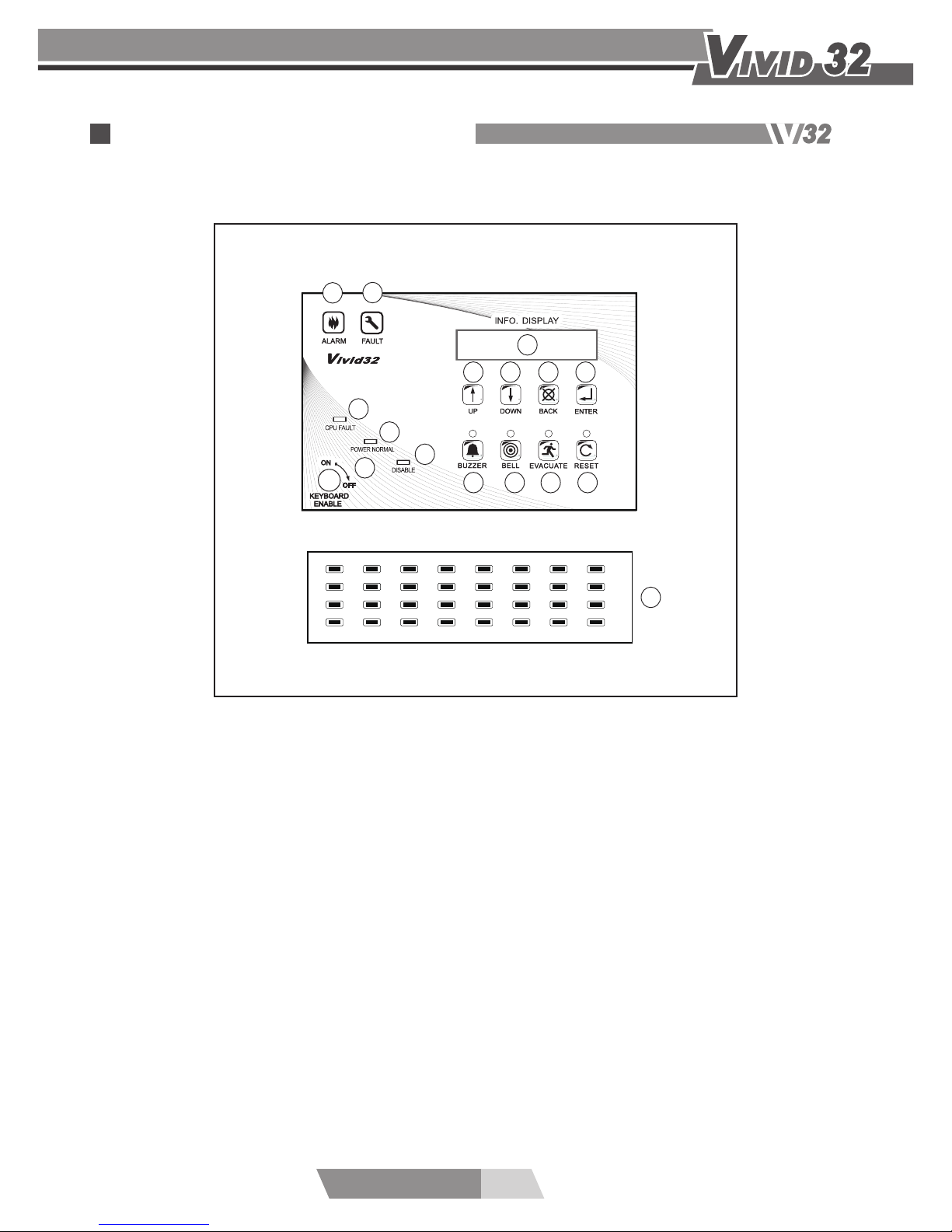
1. Fire Alarm Indicator
2. Fault Indicator
3. CPU Fault Indicator
4. Power Normal Indicator
5. Disable Indicator
6. Information Display
7. Keyboard Enable Switch
8. “UP” Switch
9. “DOWN” Switch
10. “BACK” Switch
11. “ENTER” Switch
12. Buzzer Mute Switch
13. Alarm Bell Silence Switch
14. Evacuate Switch
15. Reset Switch
16. Zone Indicators (optional)
2
VIVID32
OPERATING MANUAL
3
7
6
8 9 10 11
12
16
13 14 15
5
4
1
9
17
25
2
10
18
26
3
11
19
27
4
12
20
28
5
13
21
29
6
14
22
30
7
15
23
31
8
16
24
32
2
1
2. Control Board Description

3
VIVID32
OPERATING MANUAL
2.1 LED Indicators
1. Fire Alarm Indicator: A red light indicates the Fire Alarm Control Panel has received
a fire signal.
2. Fault Indicator: A yellow light indicates a fault in the fire alarm system.
3. CPU Fault Indicator: A yellow light indicates the CPU is not normal .
4. Power Normal Indicator: A green light indicates the Fire Alarm Control Panel is in
normal condition.
5. Disable Indicator: A yellow light indicates a zone han been disabled .
6. Information Display: It provides a read-out of system conditions.
2.2 Keypad Switches
7. Keyboard Enable Switch: When the switch is turned on, it means that the keyboard
is enable.
8. UP Switch: Pressing this switch shows the previous item on the page. It can
also be used to change the time and passwords by increasing the value progressively.
9. Down Switch: Pressing this switch shows the next item on the page. It can also be
used to change the time and passwords by decreasing the value progressively.
10. Back Switch: Pressing this switch shows the previous page. When changing the setup
of time and passwords, pressing this switch can shift control to the previous decimal place.
11. Enter Switch: Pressing this switch shows the next page. When changing the setup
of time and passwords, pressing this switch can shift contorl to the next decimal place.
12. Buzzer Mute Switch: If there is an alarm or fault in the system, pressing this switch
can disable the buzzer and the indicator can go on. When a new signal is received,
the buzzer function will be restored. If the switch is pressed again, the buzzer function
will be restored and the indicator will go out. If the switch is pressed for more than
2 seconds, the indicator will flash and the buzzer will remain disabled despite any new
signals.
13. Alarm Bell Silence Switch: If there is an alarm or a fault in the system, pressing
this switch can disable the relay output to the bells and the indicator can go on.
When a new signal is received, the bell function will be restored. If the switch is
pressed again, the bell function will be restored and the indicator will go out. If the
switch is pressed for more than 2 seconds, the indicator will flash and the bells will
remain disabled despite any new signals.
2. Control Board Description

4
VIVID32
OPERATING MANUAL
2.3 Access Level
14. Evacuate Switch: Press this switch, and the system can generate an alarm
and activate all warning devices.
LEVEL 1
Any operations on the
UP, DOWN, BACK or ENTER button on the panel board can review
status information.
LEVEL 2
Turn the “
KEYBOARD ENABLE” switch to the “ON” position to access to the LEVEL 2 so
that the
BUZZER, BELL, EVACUATE, or RESET button on the control panel is available to
use. In addition, Zone Disable, Date/Time, Delay Timer and Backlight Timer can be set up.
LEVEL 3
In this level, all operations are based on the
LEVEL 2. Enabling “Memory Data Delete”
requires to input a 4-digit security code to enter
LEVEL 3 in order to clear all memory
data.
LEVEL 4
There is a screw (“ ” form) on the side of the panel door. It requires a Phillips screwdriver
to turn on to access to LEVEL 4 to change the hardware settings of the main board, such
as DIP switch settings and JUMP settings.
15. Reset Switch: Pressing this switch can reset the panel. The rest indicators will light
up and after a 5-second delay, the system will be restored to the surveillance status.
16. Zone Indicators(optional): It shows “disable” & “fault” & “fire alarm” signal in the
individual loop. The light of LED is yellow or red.
It shows flash yellow light when fault loops occurred.
It shows continuous yellow light when disabled loops occurred.
It shows continuous red light when a fire alarm occurred.
2. Control Board Description
5
VIVID32
OPERATING MANUAL
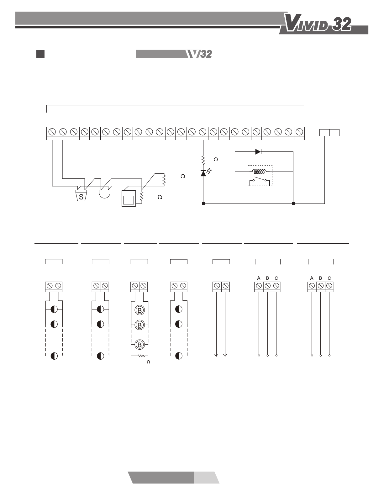
3.Wiring Diagram
3.1 Zone Input/Output
24V
24V DC
+
-
AUX
24V DC
+
-
4.7k
24V DC
SND1
+
-
AUX
24V DC
+
-
DIALLER
To Dialing
Relay
Output
Device
Indicating Lamp
24Vdc Output
Sounder
24Vdc Output
Dialler Output
Fire Relay Output
Fault Relay Output
To Relay
Output
Device
FIRE
To Relay
Output
Device
FAULT
Z1
E1
+
-
Z2
E2
+
-
Z3
E3
+
-
Z4
E4
+
-
Z5
E5
+
-
Z6
E6
+
-
Z7
E7
+
-
Z8
E8
+
+
-
-
2k
220
P
Terminal
4.7k
Relay 24V
24V
6
VIVID32
OPERATING MANUAL
ZN
.....
P
P
P
P
220 /1W 220 /1W
C.
4.7k
SND1
4.7k
SND2
4.7k
24V DC
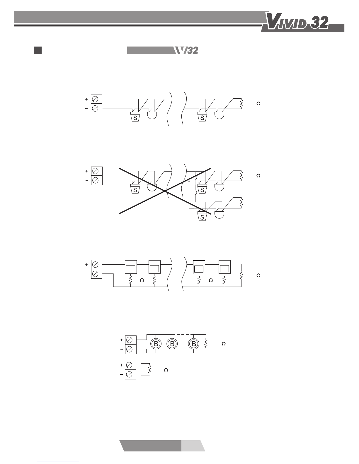
Wiring Diagram A is a recommended connection. The maximum number of
connected smoke detectors is 30 for each zone (not including the mechanic
-type heat detectors.)
Wiring Diagram B is an improperly connected one. Do not connect a detector
or an end of resistor with another detector in paralled way.
Wiring Diagram C .When connecting a manual call point to a zone, please
use a 220 Ohm resistor and install the 4.7K ohm end of line resistor.
Fire alarm control panel is equipped with two sets of Area Bells contacts.
When connecting one set of bell contacts, please be sure to connect the end
of resistor to avoid bell malfunction. Please install the 4.7K ohm resistor
across the unused bell contacts as well.
ZN
.....
A.
4.7k
ZN
B.
.....
4.7k
3.2 Zone Wiring:
3.3 Alarm Bell Wiring:
3.Wiring Diagram
 Loading...