

Horing LIH AH-02412, AH-02412E, AH-02412L Operating Manual
Fire Alarm Control Panel
Operating Manual
AH-02412
FAMILY
C
2005-04E1
I
AH-02412 FAMILY
ITEM
Introduction and Characteristics
Fire Alarm System Assembly Diagram
Fire Alarm Signal Flow Chart
Panel Descriptions
Standard Detector Wiring Method
Method of Wiring
Wiring Principle
Operating Instructions
1.Fire Surveillance
2.Fire Alarm
3.Reset
4.Fault Alarm
5.Standby Power
6.Alarm Relay Output
7.Fault Relay Output
8.Control Board LED Test
9.Occurrence of Alarm Signal during Testing
10.The Display Module LCD (AH-02412L)
11.Extinguishing Facility (AH-02412E)
Installation Location
Important Notes On Maintenance
1.Normal State of Control Panel
2.Maintenance of Devices
3.Overall Maintenance
Trouble Shooting
1.Malfunction of Zone Indicator & Combination PBL Box
2.Functions of Fuses
3.Causes of Burnt Fuses & Inspection Guidelines
4.Combination PBL Fire Indicating Lamp & Alarm Bell malfunction
5.Zone
“ Fault/Disable ”
Indicator & “ Fault ” Indicator light up
6.AC Power Fault
7.Standby Power Fault
8.PCB Connection Fault
9.Ground Fault
10.Zone “Alarm” Indicator & Fire “Alarm” In dicator light up
Main Specifications
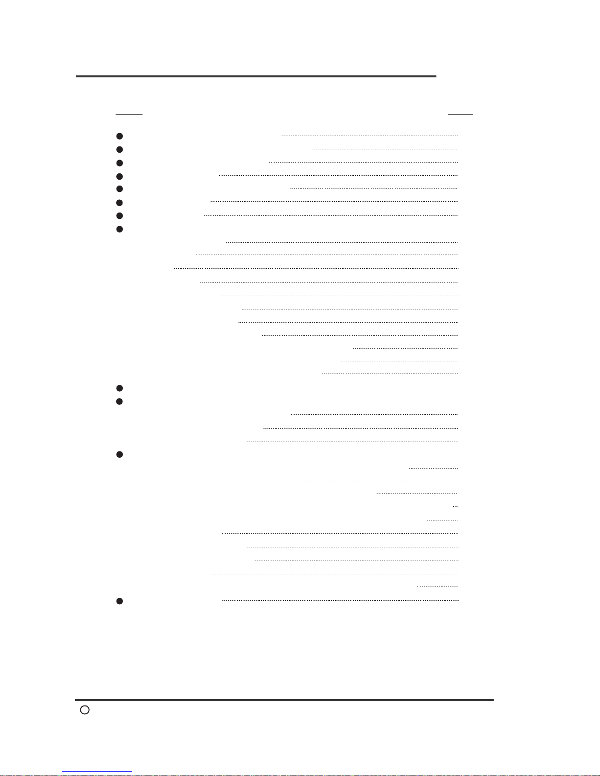
CONTENTS
1
2
2
3-5
6
7,8
9
10
10
10
11
11
11
11
11
11
11
12
13
13
13
14
14
14
15
15
15
16
16
Page
13
16
16
16

AH-02412 FAMILY
C
2005-04E1
1
AH-02412 FAMILY
Due to the creativity and progress of fire fighting technology among
highly developed countries, we never give up any chance to upgrade
our new generation fire alarm control panel. We are not only pursuing
higher technology level, but also compact design to meet national
quality standard.
..
This digital control panel primary uses processor to handle relevant
signal, which improve most weak points of traditional control panel.
See below for more details.
(1)The use of microprocessor has improved the unit's correctness
that used to be affected by bad characteristic of traditional devices.
(2)Uses digital mode to transmit and control signal process, which
highly increase the precision of signal.
(3)Internal control voltage uses 5V that prevent burning circuit caused
by traditional high voltage.
(4)Module type design simplified entire system, function up-grade just
has to change related module and no need big work to complete it.
Thus, users are able to save big bucks on up-grade or repair cost.
(5)Microprocessor can be revised according to user's request, its
expand ability has much greater than traditional ones.
(6)Shortage of terminal has not seen on this unit, up to four sets of
signal transfer contacts (relay outputs) are added for new design.
(7)Zone isolating button and control board switches are electronic-type
and used digital 0 and 1 signals for switch control signal. Also they
will not damaged by abnormal high voltage because of undirected
control high voltage and interfered by dust, this phenomenon
usually happened on mechanical-type switch.
Introduction and Characteristics
Introduction
Characteristics
AH-02412 FAMILY
C
2005-04E1
Fire Alarm System Assembly Diagram
2
AH-02412 FAMILY
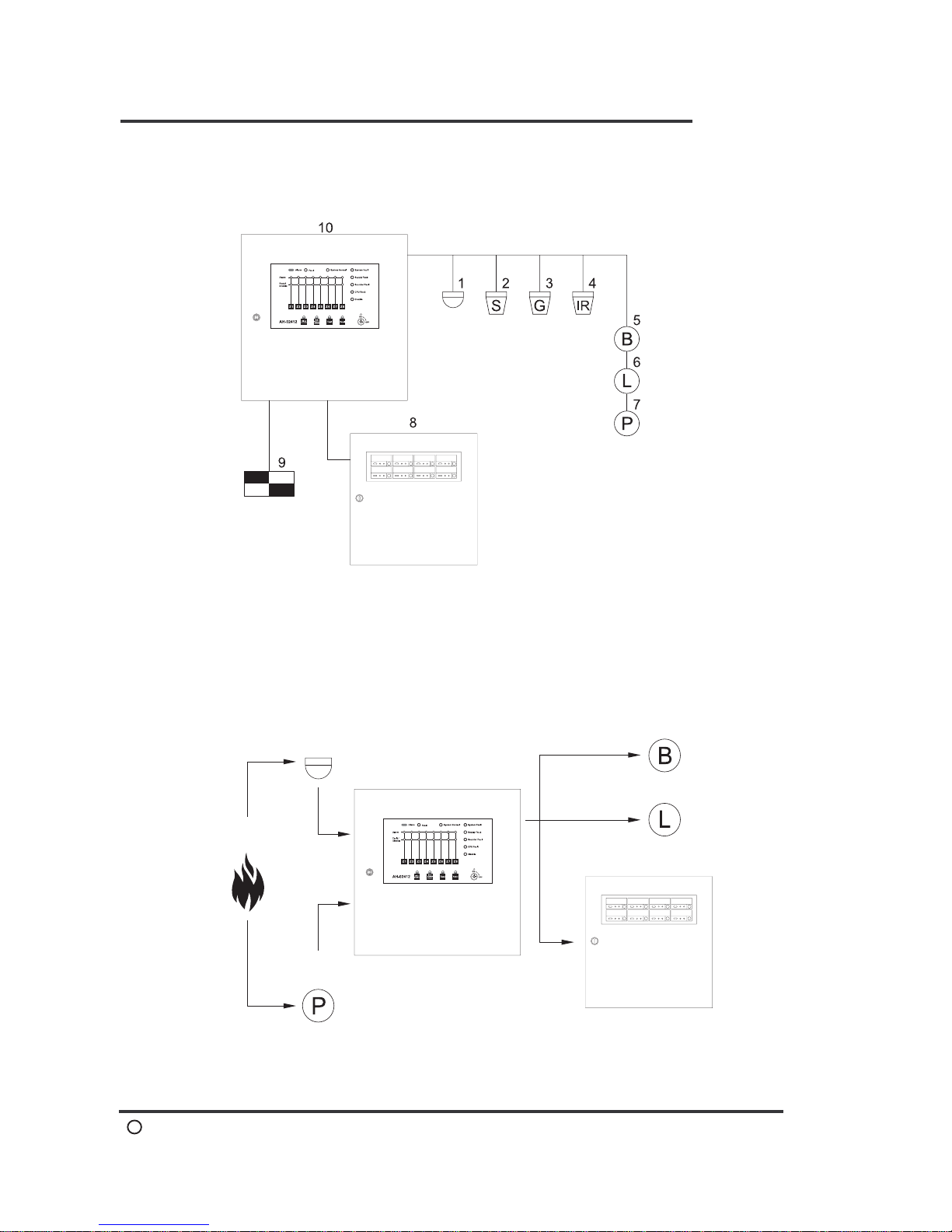
Fire Alarm System Assembly Diagram
Fire Alarm Signal Flow Chart
1-Heat Detector
2-Smoke Detector
3-Gas Detector
4-Flame Detector
5-Alarm Bell
6-Indicating Lamp
7-Manual Call Point
8-Annunciator
9-Extinguishing Device
10-Control Panel
1.Occurrence
of fire
2-1.Detector
2-2.Manual Call Point
3.Control Panel
4-1.Alarm Bell
4-2.Indicating Lamp
4-3.Annunciator
AH-02412 FAMILY
C
2005-04E1
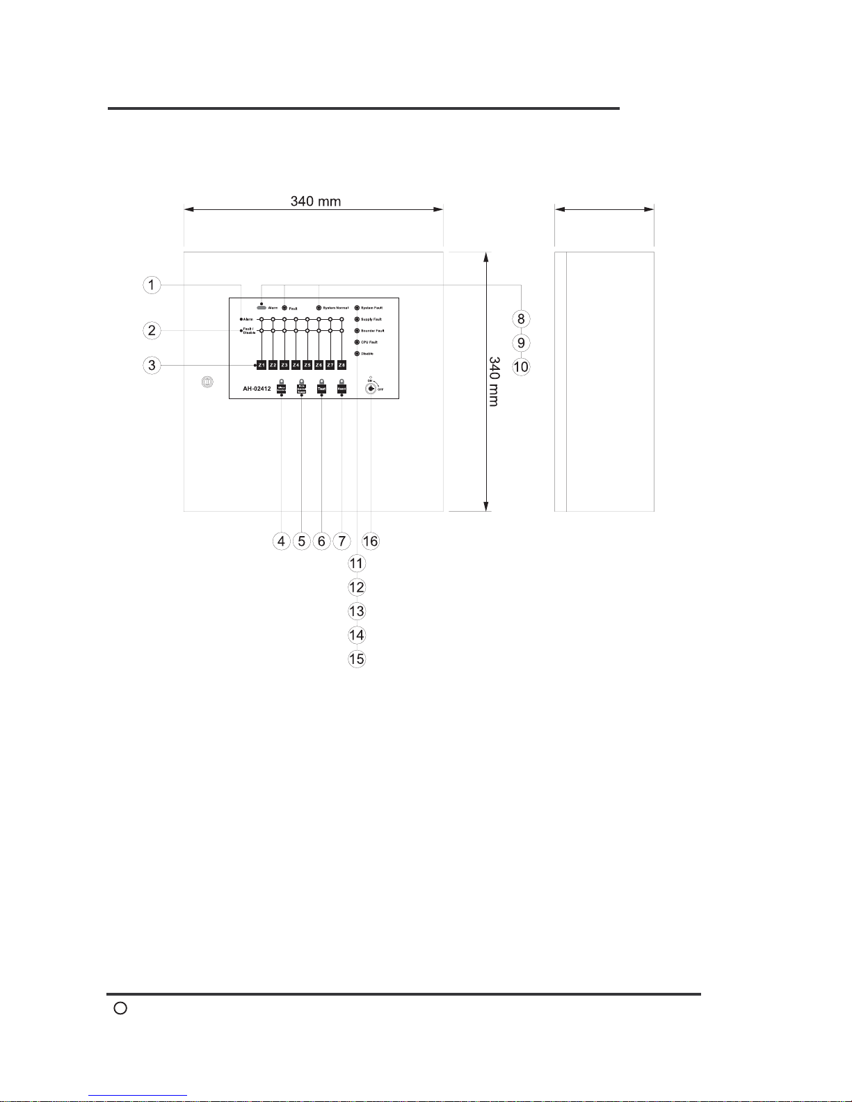
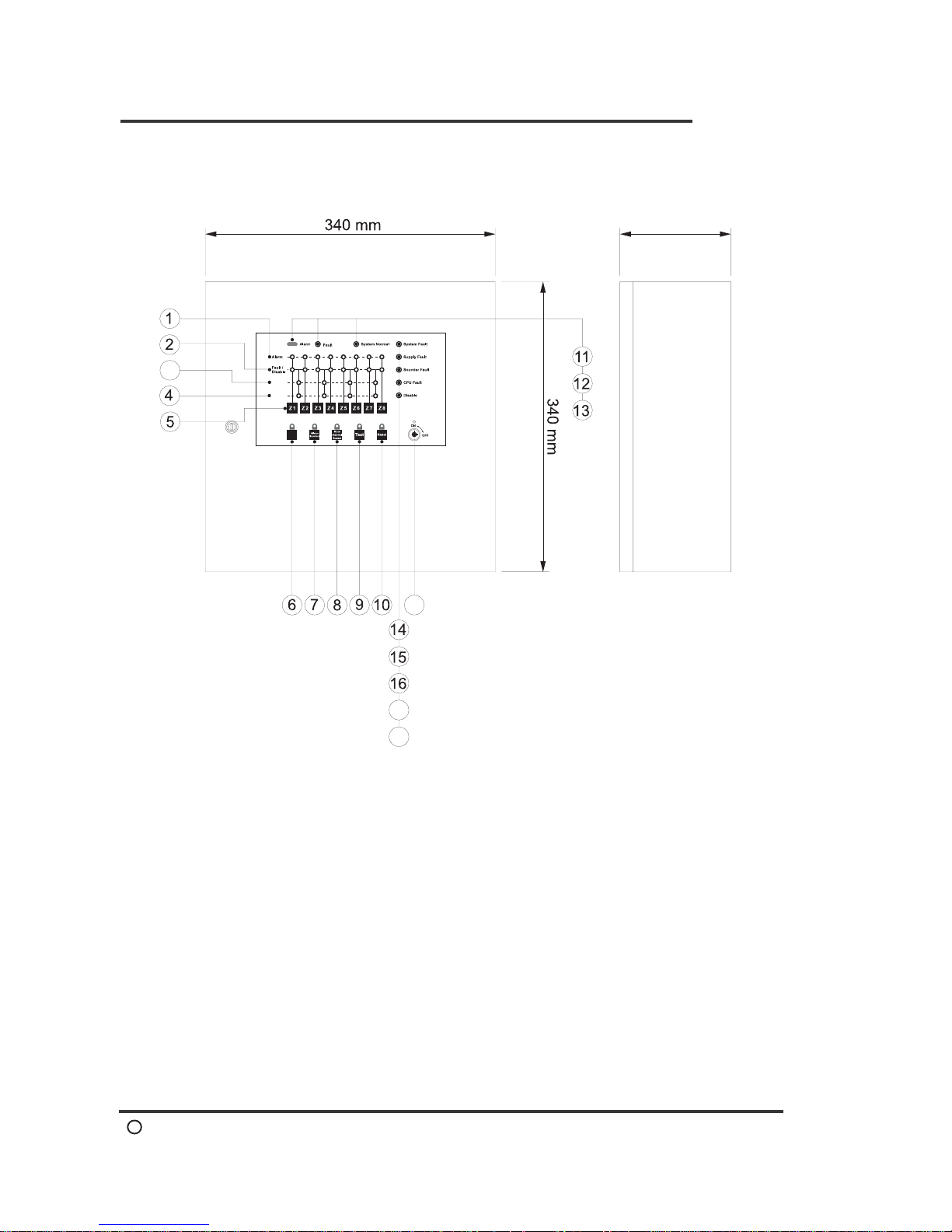
Panel Description(AH-02412)
3
AH-02412 FAMILY
Description
1.Zone Alarm LED
2.Zone Fault/Disable LED
3.Zone Disable
4.Silence Sounders
5.Mute Internal Buzzer
6.Lamp Test
7.Reset
8.Fire Alarm LED
9.Fault LED
10.System Normal LED
11.System Fault LED
12.Supply Fault LED
13.Sounder Fault LED
14.CPU Fault LED
15.Disable LED
16.Key Switch
Dimensions and Specifications
130 mm
AH-02412 FAMILY
C
2005-04E1
Panel Description(AH-02412E)
4
AH-02412 FAMILY
Description
Dimensions and Specifications
Nac
Active
Trouble
(Nac)
3
17
18
19
1.Zone Alarm LED
2.Zone Fault / Disable LED
3.Nac Active LED
4.Nac Fault LED
5.Zone Disable
6.Nac
7.Silence Sounders
8.Mute Internal Buzzer
9.Lamp Test
10.Reset
11.Fire Alarm LED
12.Fault LED
13.System Normal LED
14.System Fault LED
15.Supply Fault LED
16.Sounder Fault LED
17.CPU Fault LED
18.Disable LED
19.Key Switch
130 mm
 Loading...