

Horiba Scientific LAQUAact-EC110, LAQUAact-EC120 Instruction Manual

Handheld Conductivity Meter
LAQUAact-EC110
LAQUAact-EC120
Instruction Manual
CODE:GZ0000427797


Preface
This manual describes the operation of the Handheld Conductivity Meter LAQUAactEC110, LAQUAact-EC120.
Be sure to read this manual before using the product to ensure proper and safe
operation of the product. Also safely store the manual so it is readily available whenever
necessary.
Product specifications and appearance, as well as the contents of this manual are
subject to change without notice.
■ Warranty and responsibility
HORIBA, Ltd. warrants that the Product shall be free from defects in material and
workmanship and agrees to repair or replace free of charge, at option of HORIBA, Ltd.,
any malfunctioned or damaged Product attributable to responsibility of HORIBA, Ltd. for
a period of two (2) years from the delivery unless otherwise agreed with a written
agreement. In any one of the following cases, none of the warranties set forth herein
shall be extended;
・ Any malfunction or damage attributable to improper operation
・ Any malfunction attributable to repair or modification by any person not authorized
by HORIBA, Ltd.
・ Any malfunction or damage attributable to the use in an environment not specified in
this manual
・ Any malfunction or damage attributable to violation of the instructions in this manual
or operations in the manner not specified in this manual
・ Any malfunction or damage attributable to any cause or causes beyond the
reasonable control of HORIBA, Ltd. such as natural disasters
・ Any deterioration in appearance attributable to corrosion, rust, and so on
・ Replacement of consumables
HORIBA, LTD. SHALL NOT BE LIABLE FOR ANY DAMAGES RESULTING FROM ANY
MALFUNCTIONS OF THE PRODUCT, ANY ERASURE OF DATA, OR ANY OTHER
USES OF THE PRODUCT.
■ Trademarks
・ Microsoft, Windows are registered trademarks or trademarks of Microsoft Corporation
in the United States and other countries.
Other company names and brand names are either registered trademarks or trademarks
of the respective companies. (R), (TM) symbols may be omitted in this manual.
CODE:I20050200003200635710GZ0000427797
January, 2016 2016 HORIBA, Ltd.
I
Regulations
■ EU regulations
●Conformable standards
This equipment conforms to the following standards:
EMC: EN61326-1
Class B, Basic electromagnetic environment
Safety: EN61010-1
RoHS: EN50581
9. Monitoring and control instruments
Warning: This product is not intended for use in industrial environments. In an
industrial environment, electromagnetic environmental effects may
cause the incorrect performance of the product in which case the
user may be required to take adequate measures.
●Installation environment
This product is designed for the following environment.
・Overvoltage Category II
・Pollution degree 2
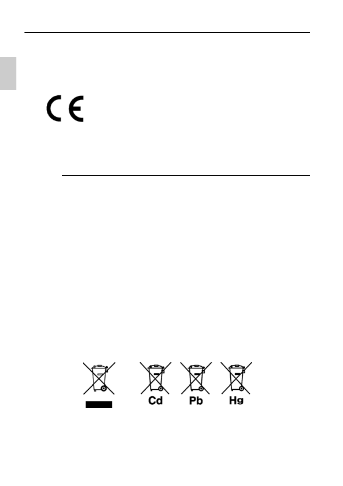
●Information on disposal of electrical and electronic
equipment and disposal of batteries and accumulators
The crossed out wheeled bin symbol with underbar shown on the product or
accompanying documents indicates the product requires appropriate treatment,
collection and recycle for waste electrical and electronic equipment (WEEE) under the
Directive 2012/19/EU, and/or waste batteries and accumulators under the Directive
2006/66/EC in the European Union.
The symbol might be put with one of the chemical symbols below. In this case, it satisfies
the requirements of the Directive 2006/66/EC for the object chemical.
This product should not be disposed of as unsorted household waste.
Your correct disposal of WEEE, waste batteries and accumulators will contribute to
reducing wasteful consumption of natural resources, and protecting human health and
the environment from potential negative effects caused by hazardous substance in
products.
Contact your supplier for information on applicable disposal methods.
●Authorised Representative in EU
HORIBA UK Limited
2 Dalston Gardens, Stanmore, Middx HA7 1BQ, UK
II
Regulations
■ FCC rules
Any changes or modifications not expressly approved by the party responsible for
compliance shall void the user's authority to operate the equipment.
●WARNING
This equipment has been tested and found to comply with the limits for a Class A digital
device, pursuant to part 15 of the FCC Rules. These limits are designed to provide
reasonable protection against harmful interference when the equipment is operated in a
commercial environment. This equipment generates, uses, and can radiate radio
frequency energy and, if not installed and used in accordance with the instruction
manual, may cause harmful interference to radio communications.
Operation of this equipment in a residential area is likely to cause harmful interference in
which case the user will be required to correct the interference at his own expense.
■ Korea certification
●
■ Taiwan battery recycling mark
III
For your safety
■ Hazard classification and warning symbols
Warning messages are described in the following manner. Read the messages and
follow the instructions carefully.
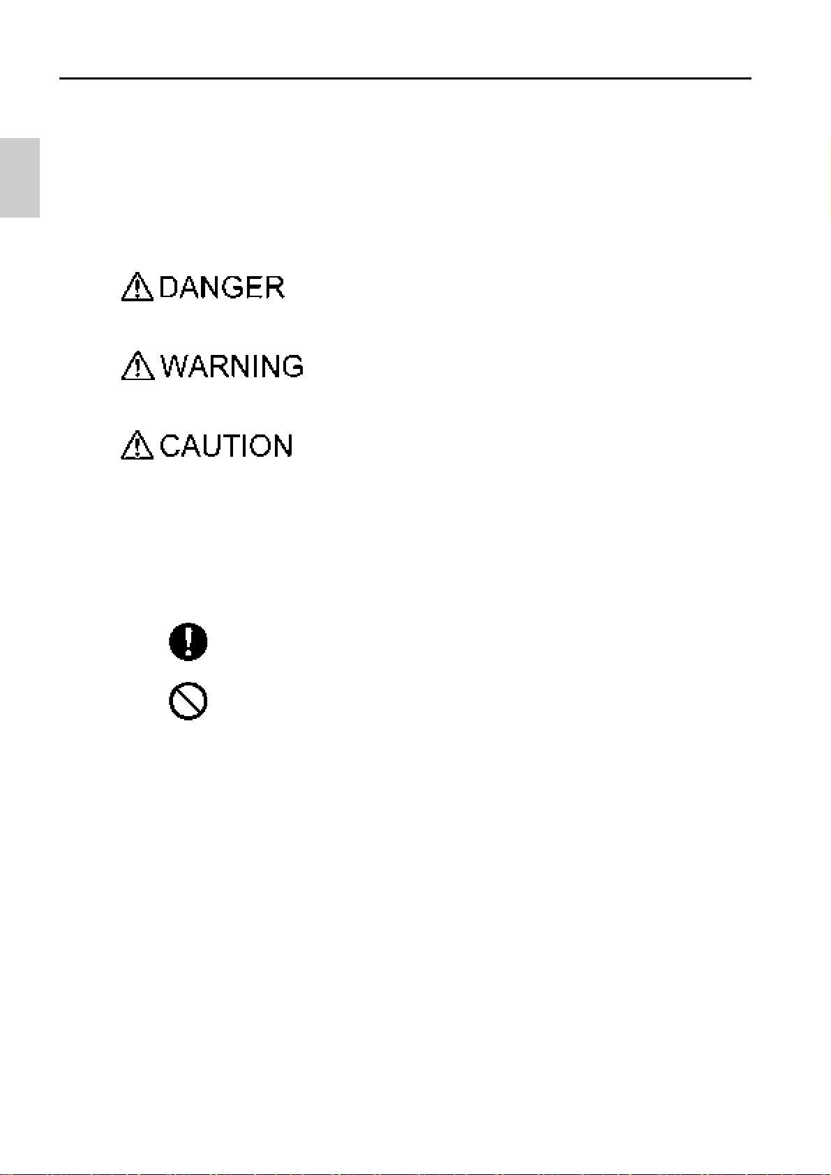
●Hazard classification
This indicates an imminently hazardous situation which, if
not avoided, will result in death or serious injury . This is to
be limited to the most extreme situations.
This indicates a potentially hazardous situation which, if
not avoided, could result in death or serious injury.
This indicates a potentially hazardous situation which, if
not avoided, may result in minor or moderate injury . It may
also be used to alert against unsafe practices.
●Warning symbols
Description of what should be done, or what should be followed
Description of what should never be done, or what is prohibited
IV
For your safety
WARNING
CAUTION
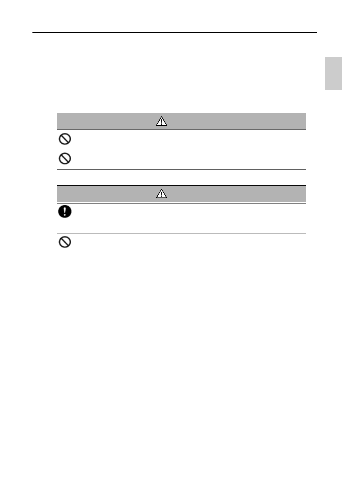
■ Safety precautions
This section provides precautions for using the product safely and correctly and to
prevent injury and damage. The terms of DANGER, WARNING, and CAUTION indicate
the degree of imminency and hazardous situation. Read the precautions carefully as it
contains important safety messages.
●Instrument and electrode
Do not use an unspecified AC adapter.
Otherwise, it may heat up or be ignited resulting in a fire or an accident.
Do not disassemble or modify the instrument.
Otherwise, it may heat up or be ignited resulting in a fire or an accident.
Broken glass
Broken glass may cause injury. The outer tube and tip of an electrode are
made of glass. Handle them with care.
Do not use the RS-232C communication and the AC adapter under wet or
humid conditions. Otherwise, it may cause a fire, electric shock, or
breakage.
V
●Battery
WARNING
CAUTION
Keep batteries out of reach of children. If someone accidentally swallows a
battery, consult a doctor immediately.
If alkaline fluid from a battery gets into the eyes, do not rub the eyes, rinse
with clean water immediately and then consult a doctor.
Contact with alkaline fluid could cause blindness.
Do not put batteries in a fire, expose to heat, disassemble or remodel.
Doing so could case fluid leakage, overheating or explosion.
Do not remove or scratch the external label of the battery.
Doing so could cause injury to hands and fingers.
For your safety
VI

For your safety
■ Product handling information
●Operational precautions (instrument)
・Only use the product including accessories for their intended purpose.
・Do not drop, crash, or give any physical impact on the instrument.
・The instrument is made of solvent-resistant materials but that does not mean it is
resistant to all chemicals. Do not dip the instrument in strong acid or alkali solution, or
wipe with such solution.
・If the instrument is dropped into water or gets wet, wipe it using soft cloth. Do not heat
to dry it with a hair-dryer (or the like).
・The instrument has a dust-proof and waterproof structure. Waterproof performance is
following specification: the instrument does not malfunction even when immersed in
water of 1 m depth for 30 minutes.
This does not mean to guarantee non-destructive, trouble-free, dust-proof, and
waterproof performance in all situations. If the instrument is correctly handled
according to the descriptions in this manual, the instrument provides dust-proof and
waterproof performance.
・When replacing the batteries with an AC adapter or a serial cable connected the
instrument does not have the dust-proof and waterproof performance. The dust-proof
and waterproof performance is maintained only when the covers are attached
correctly.
・After replacing the batteries with an AC adapter or a serial cable connected make sure
that the waterproof packing attached to each cover is not deformed or discolored, or
has foreign matter adhering to it. If the waterproof packing is deformed, discolored or
has foreign matter adhering to it, or dust could get inside, water leaks could occur that
could lead to instrument malfunction.
・To disconnect an electrode, AC adapter cable or serial cable, hold the connector and
pull it off. If you pull at the cable, it may cause a breakage.
・The RS-232C communication between the instrument and a personal computer
(referred to as PC in the rest of this document) may fail because of environmental
conditions, such as (radio/electromagnetic) noise.
・Do not replace the batteries in a dusty place or with wet hands while an AC adapter or
a serial cable is connected. Dust or moisture could get inside the instrument, possibly
causing instrument malfunction.
・Do not use the tip of a nail or an object with a sharp end to press the keys.
・If the power supply is interrupted while measurement data is being saved in the
instrument, the data could be corrupted.
・A NiMH rechargeable battery can be used in this instrument, but the battery used in
the instrument cannot be charged using the AC adapter.
VII

For your safety
●Operational precautions (battery)
・Do not short-circuit a battery.
・Set the + and side of the battery correctly.
・When the battery has run out or the instrument will not be used for a long time, remove
the batteries.
・Of the specified battery types, make sure to use two batteries of the same type.
・Do not use a new battery together with a used battery.
・Do not use a fully charged nickel-metal hydride battery together with a partially
charged battery.
・Do not attempt to charge a non-rechargeable battery.
●Environmental conditions for use and storage
・Temperature: 0°C to 45°C
・Humidity: under 80% in relative humidity and free from condensation
Avoid the following conditions.
・Strong vibration
・Direct sunlight
・Corrosive gas environment
・Close to an air-conditioner
・Direct wind
●Transportation
When transporting the instrument, repackage it in the original package box. Otherwise, it
may cause instrument breakage.
●Disposal
・Standard solution used for the calibration must be under neutralized before the
disposal.
・When disposing of the product, follow the related laws and/or regulations of your
country for disposal of the product.
VIII

Manual information
Note
Reference
Tip
■ Description in this manual
This interprets the necessary points for correct operation and notifies the important
points for handling the product.
This indicates the part where to refer for information.
This indicates reference information.
Description of this manual uses the screen display of EC120.
IX

M E M O
X

Contents
Preface...................................................................................I
■ Hazard classification and warning symbols................... IV
■ Safety precautions ............................................................. V
■ Product handling information ......................................... VII
■ Description in this manual................................................ IX
Part names and basic operation.........................................1
■ Names of each part .............................................................2
● Instrument....................................................................................2
● Display .........................................................................................4
● Operation key..............................................................................6
■ Basic operation....................................................................7
● Function layer..............................................................................7
● Changing the operation mode.................................................10
● Changing the measurement parameter ..................................11
● Using the backlight...................................................................12
● Entering numeric values ..........................................................13
● Saving measurement data in the internal memory................14
Measurement......................................................................15
■ Preparation.........................................................................16
● Confirmation before starting measurement...........................16
● Turning ON the instrument ......................................................17
● Connecting an electrode..........................................................20
■ Conductivity measurement ..............................................21
● Setting the instrument..............................................................22
● Performing conductivity calibration........................................38
● Performing measurement ........................................................42
● Saving measured values..........................................................43
XI

Contents
Using various functions....................................................45
■ Data functions....................................................................46
● Displaying saved data..............................................................46
● Using the automatic data save................................................47
● Deleting all saved data.............................................................50
■ Measurement setting.........................................................52
● Displaying the latest calibration..............................................52
● Changing the calibration method............................................53
● Deleting calibration data..........................................................54
■ Temperature settings........................................................56
● Calibrating temperature sensor ..............................................56
■ General settings.................................................................58
● Setting the auto stability and auto hold function..................58
● Changing the automatic power off setting (default: 30 min) 60
● Resetting to factory default settings ......................................62
● Setting the date and time.........................................................64
● Performing test printing of the printer unit............................66
■ Other settings ....................................................................68
● Printing measured values and calibration data.....................68
● Transferring saved data to a PC..............................................70
● Operating the instrument from an external device................71
Maintenance ....................................................................... 73
● Contact for maintenance..........................................................73
● Maintenance and storage of the instrument..........................73
● Environmental conditions for storage....................................73
● Maintenance and storage of the conductivity cell.................74
How to resolve errors or troubles .................................... 75
XII

Contents
■ When an error message appears.....................................75
● ERROR No.0001 Memory error..............................................75
● ERROR No.0006 Maximum calibration points exceeded....75
● ERROR No.0009 Printer error................................................76
● ERROR No.0010 Memory full.................................................76
● ERROR No.0011 Cell constant is out of range ....................76
■ Troubleshooting................................................................77
● The indicated value fluctuates.................................................77
● The response is slow................................................................77
● The indicated value does not change/No response ..............78
● The measured value is outside the display range.................78
● Repeatability of the measured value is poor..........................78
● Nothing appears when the power is turned ON.....................79
● Swelling of operation key sheet ..............................................79
● Part of the display is missing ..................................................79
Appendix.............................................................................81
■ Main specifications ...........................................................81
● Table of conductivity cell range ..............................................83
● Table of conductivity cell range (resistivity range) ...............84
■ Instrument default settings ..............................................85
■ Technical note ...................................................................86
● Conductivity standard values at various temperatures........86
■ Options...............................................................................87
XIII

M E M O
XIV

Part names and basic operation
This section describes the name of each part and the main role, function, and basic
operation method of each part.
■ Names of each part...................................................................... 2
● Instrument..............................................................................................2
● Display....................................................................................................4
● Operation key ........................................................................................6
■ Basic operation............................................................................ 7
● Function layer........................................................................................7
● Changing the operation mode ...........................................................10
● Changing the measurement parameter............................................. 11
● Using the backlight .............................................................................1 2
● Entering numeric values..................................................................... 13
● Saving measurement data in the internal memory ..........................1 4
1
Names of each part
*
* : EC120 only
*
■ Names of each part
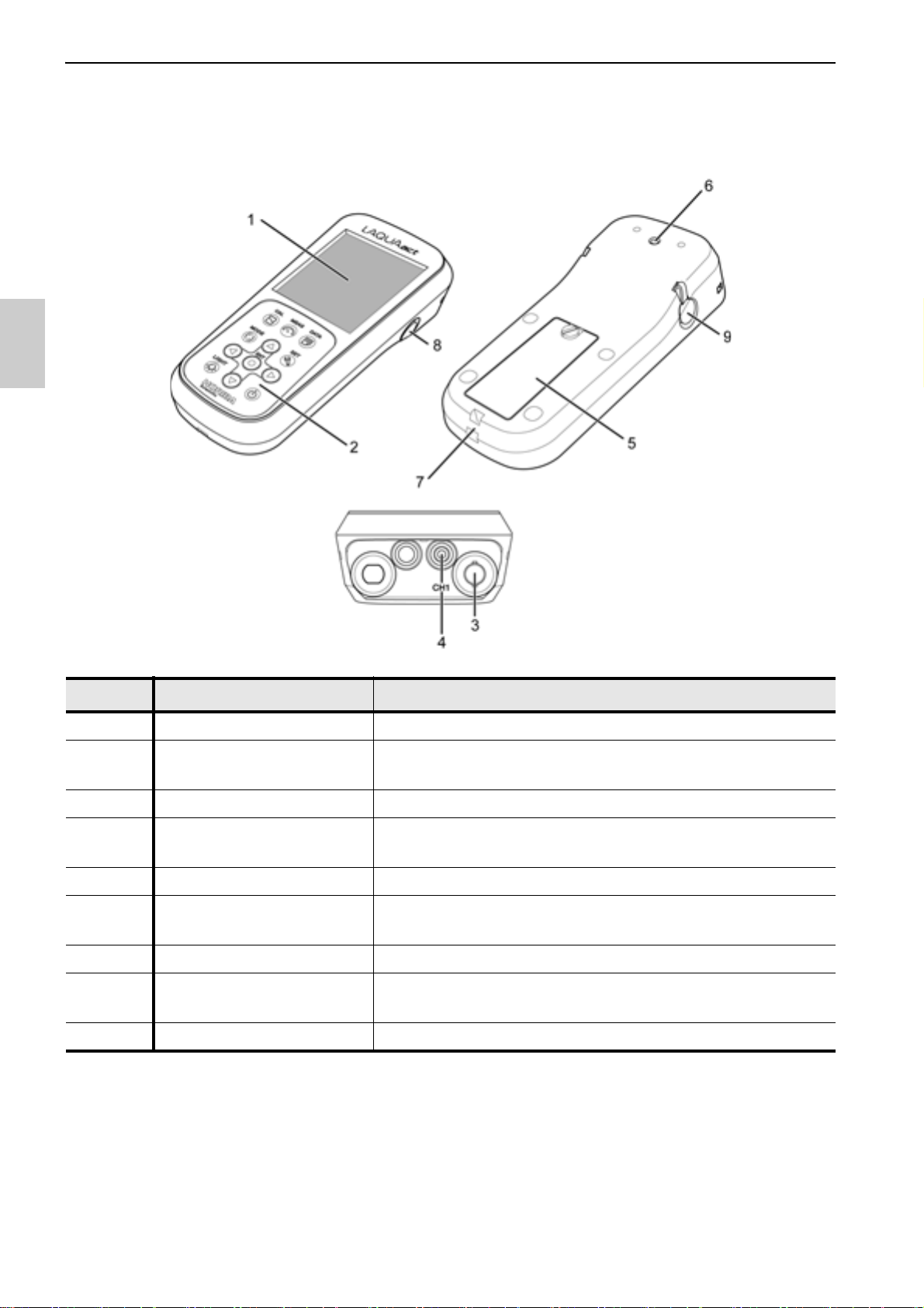
● Instrument
No. Name Function
1 Display Displays the measured value and set value and so on.
2 Operation keys
3 Electrode connector Connects the BNC connector of the electrode.
4
5 Battery cover Set batteries inside.
6
7 Strap att achment section Attach a strap.
8 Serial connector
9 AC adapter jack Connects an optional AC adapter.
Temperature
connector (T)
Electrode hook
attachment section
Used for instrument operation.
(LIGHT key: EC120 only)
Connects the temperature connector (T) of the
electrode.
Attach the electrode hook to carry with instrument.
Connects the serial cable and printer cable.
(EC120 only)
2

Names of each part
• Identification of manufacturing date
Manufacturing date can be identified from MFG No. described in the ID label on the
backside of the instrument.
Third number from the left in the MFG No. indicates manufacturing year.
Forth alphabet from the left in the MFG No. indicates manufacturing month.
The alphabet is assigned to month according to the table below.
Ex.: ID: AA6A0000 means the device manufactured in 2016 January.
JAN FEB MAR APR MAY JUN JUL AUG SEP OCT NOV DEC
ABCDEFGHJKLM
3
Names of each part
1
2
4
5
6
7
8
2
12
13
2
3
10
9
11
● Display
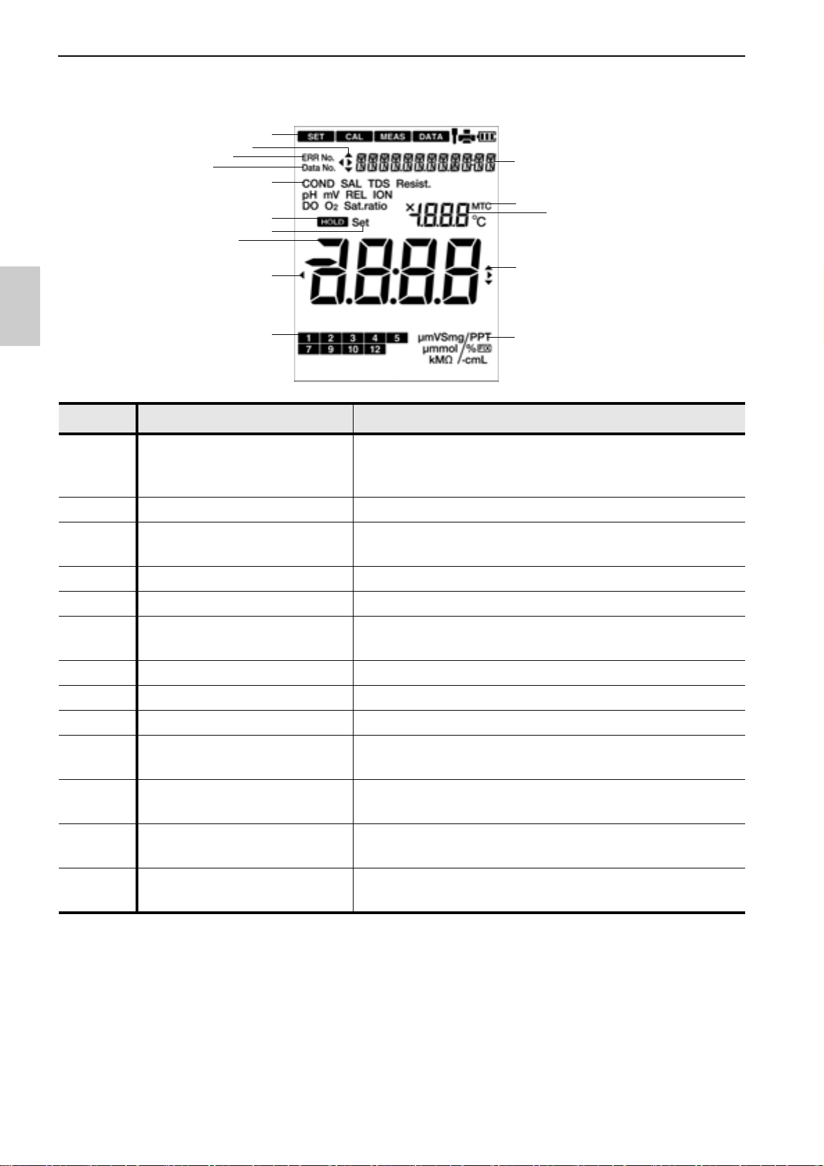
No. Name Function
Displays the current operation mode, electrode
1Status icon
status, printer or PC connection status, and
remaining battery level.
2 Direction key icon Displays the currently available direction key.
3
Date and time, set item
display area
Displays the date and time and the set items.
4 ERR No. icon Displays an error No.
5 Data No. icon Displays the data No.
6
Measurement parameter
display area
Displays the currently set measurement parameter.
7 HOLD icon Lights when the measured value display is fixed.
8 SET icon Lights when numerical values are entered.
9 Temperature display area Displays the measured and the set temperature.
10 MTC icon
11
12
Measured value, set item
display area
Standard solution
calibration history icon
13 Unit display area
Lights when the temperature setting is MTC
(optional temperature setting).
Displays the measured value and the set value.
When calibrating conductivity standard solution, the
corresponding icon lights.
Displays the unit for the measurement parameter
and the display item.
4

•Battery level display
Battery level is high.
Battery level is a little lower.
Battery level is low.
The backlight may become unavailable.
Battery has run out. Replace the batteries or use AC
adapter (option).
"ERR No. 0002" is displayed and operation is disabled.
Names of each part
5
Names of each part
● Operation key
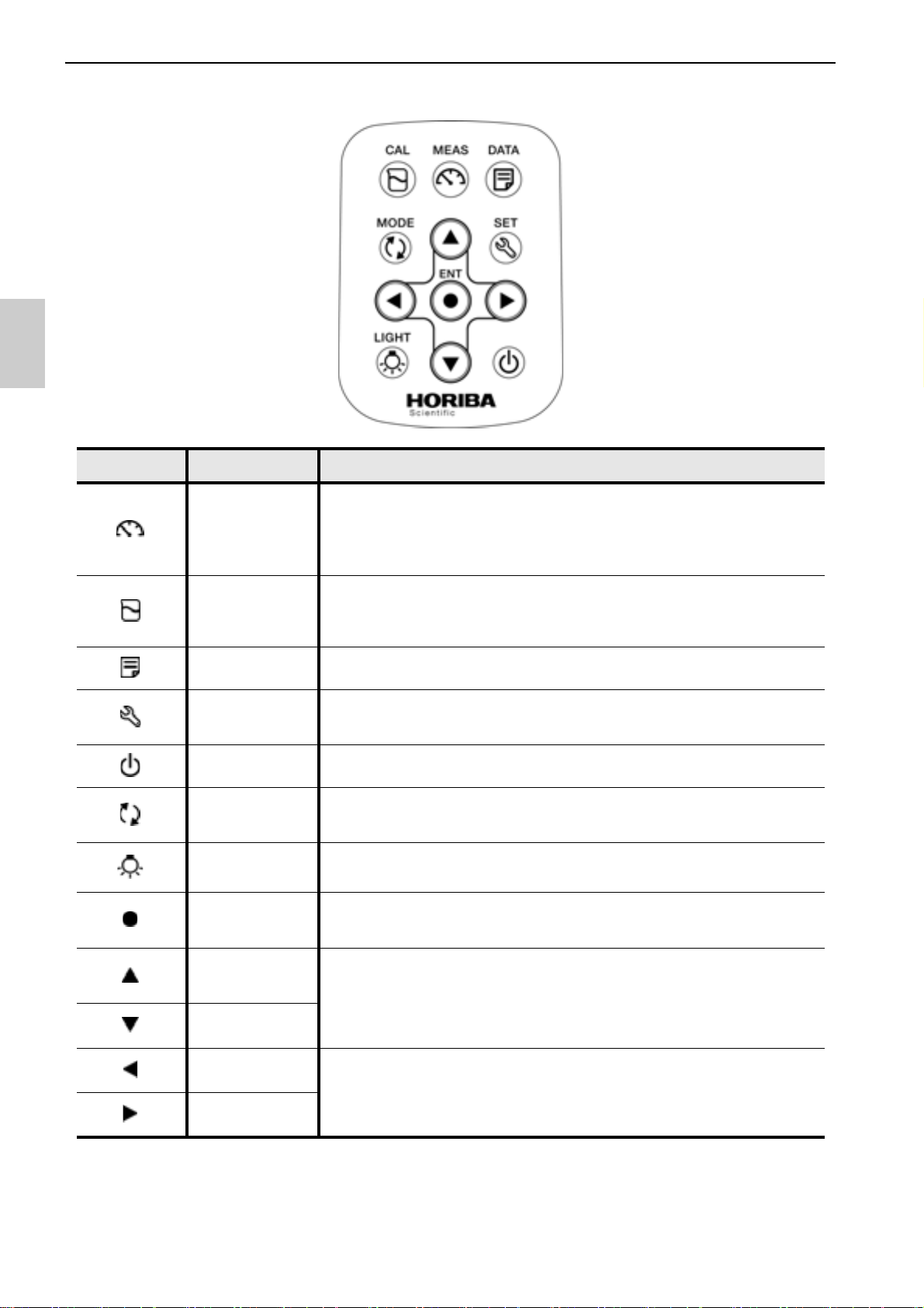
Key Name Function
MEAS key
Changes the operation mode to the measurement mode
during operation in a different mode.
Releases the fixed measurement value mode in the auto
hold mode.
Changes from the measurement mode to the calibration
CAL key
DATA key Changes from the measurement mode to the data mode.
SET key
POWER key Turns ON/OFF the power of instrument.
MODE key
LIGHT key
ENTER key
UP key
DOWN key
mode.
Start calibration in the calibration mode.
Changes from the measurement mode to the setting mode.
Starts repeatability inspection after calibration is complete.
In the measurement mode, changes measurement
parameters.
Turns on/off the back light.
(EC120 only)
Determines the selection or setting.
Save data in the measurement mode and calibration mode.
Changes the selected item.
Changes the number of the selected digit when entering
numbers.
6
LEFT key
RIGHT key
Changes the selected item.
Changes the selected digit when entering numbers.
Basic operation
■ Basic operation
● Function layer
The function layer of the data mode and setting mode is shown as below.
"dX" and "PXX" indicates the program number which is shown in the screen of the
instrument.
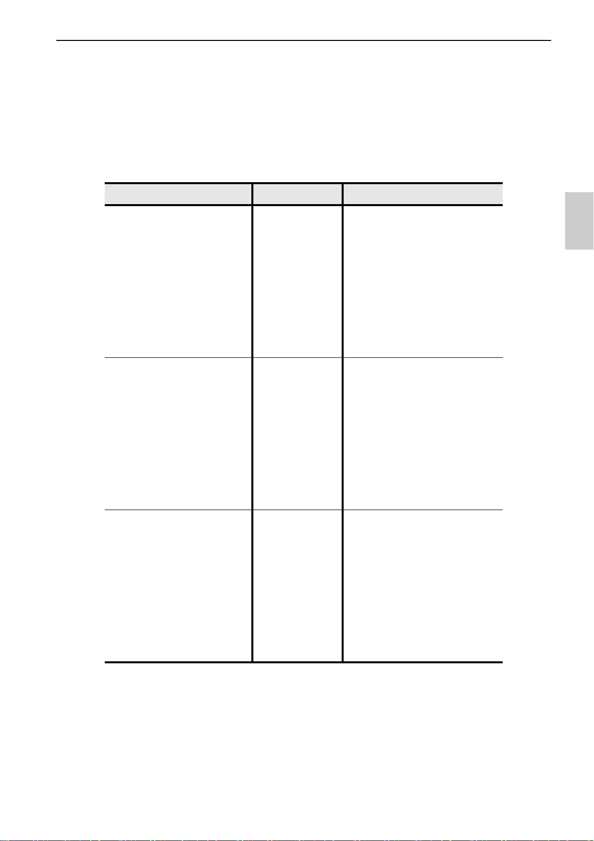
• Data mode
Screen Layer Description
d1: DATA OUT Saved data display
d2: AUT LOG Automatic data save setting
(EC120 only)
d3: DATA CLR Deletion of saved data
7
Basic operation
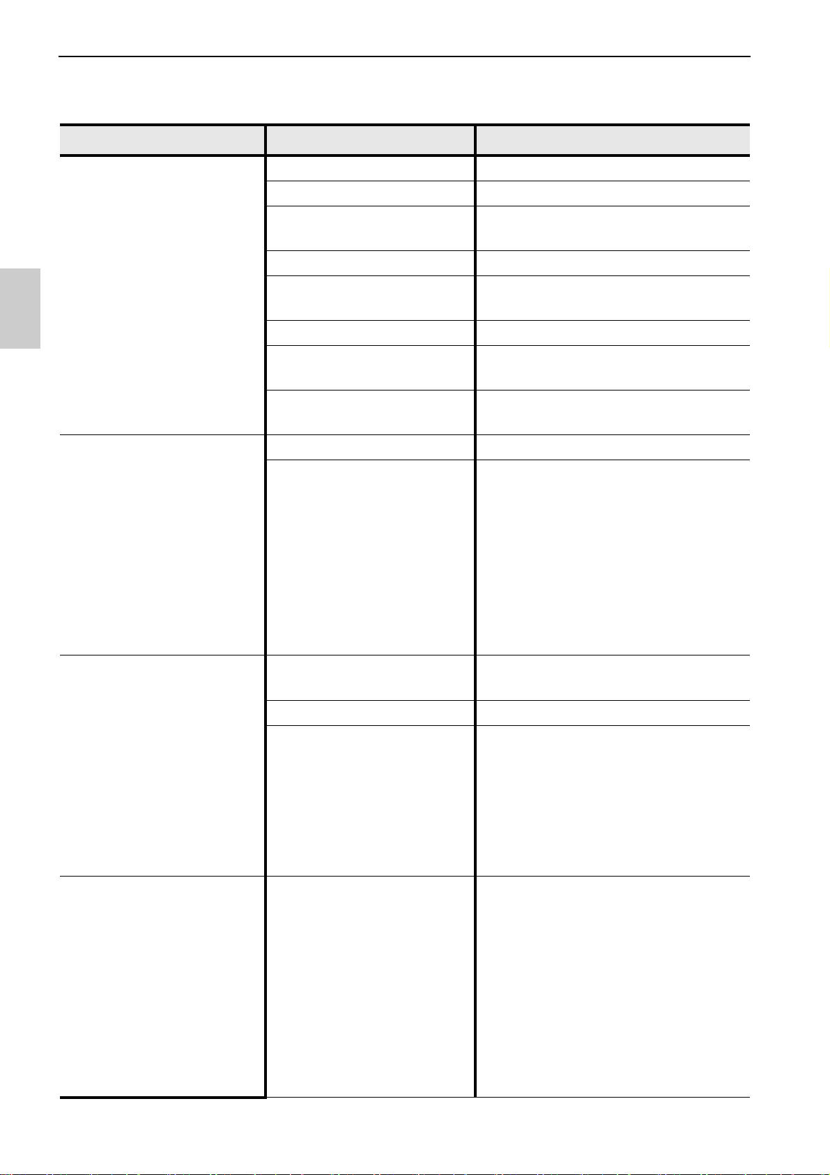
• Setting mode
Screen Layer Description
P1: COND Conductivity measurement settings
P11: CELL Cell constant setting
P12: UNIT Selection of unit:
S/cm, S/m, mS/cm FIX
P13: CAL DATA Calibration data display
P14: AUTO CAL Selection of auto calibration,
manual calibration
P15: CAL CLR Deletion of calibration data
P16: TEMP CF Selection of temperature
conversion: 0 to 10%/°C
P17: TEMP REF Reference temperature setting:
15°C to 30°C
P2: TDS TDS measurement settings
P21: TDS TYPE Selection of TDS calculation
method: Linear, 442, En27888,
NaCl
P3: SALT Salinity measurement settings
(EC120 only)
P31: UNIT Selection of unit: ppt, %
P32: SALT TYP Selection of salinity calculation
method: NaCl, Sea water
8
P4: TEMP Temperature settings
Selection of temperature
conversion: ATC, MTC
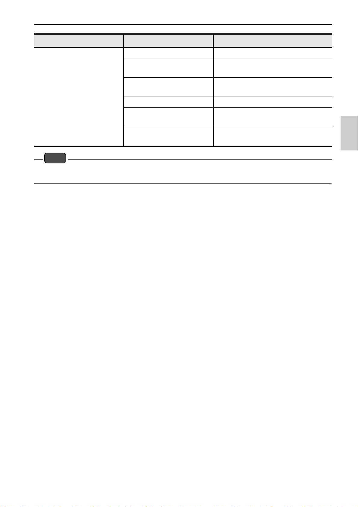
Basic operation
Note
Screen Layer Description
P5: GEN General settings
P51: MEAS Selection of auto hold type:
auto stability, auto hold
P52: AUTO OFF Automatic power off setting:
0 min to 30 min
P53: RESET Initialization settings
P54: DATE Date and time setting
(EC120 only)
P55: PRINT Test print
(EC120 only)
The indication of screen shown in this manual is based on EC120. The program numbers of
EC110 is different from those of EC120.
9
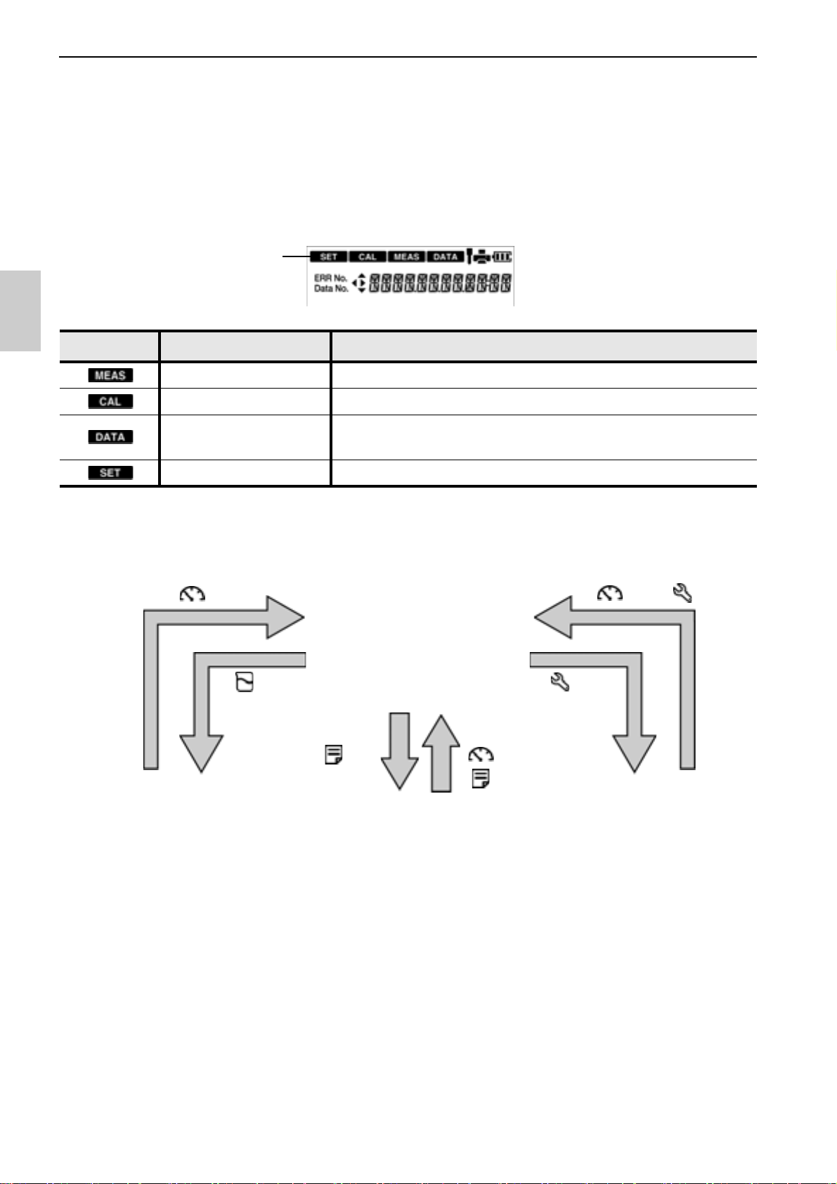
Basic operation
Status icon
Data mode Setting modeCalibration mode
key
key
key or key
key
key or
key
key
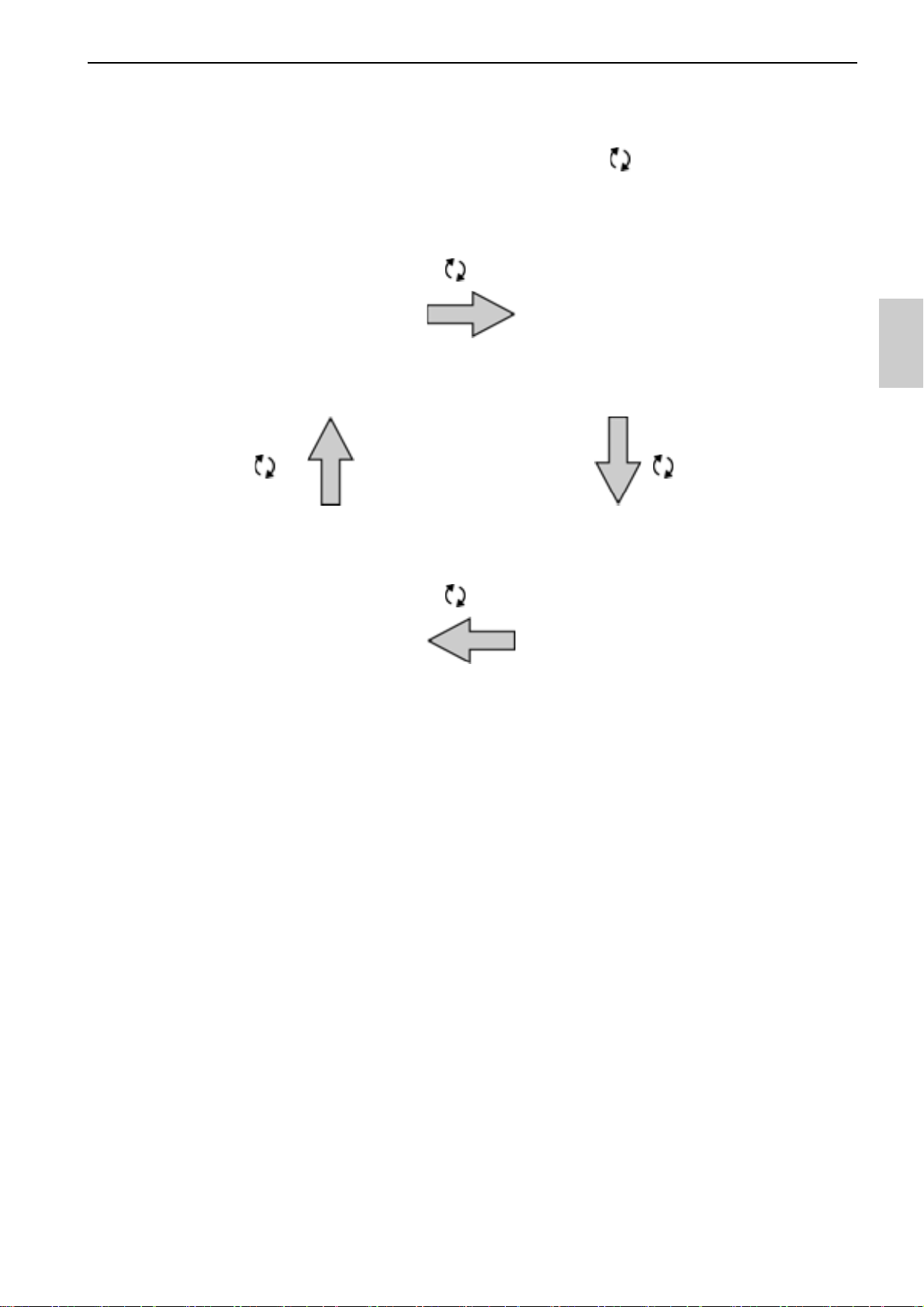
● Changing the operation mode
Change the operation mode from four available modes depending on the purpose of use.
The status icon indicates the current mode.
You can change the operation mode using the corresponding key. However changing to
the calibration mode, data mode, or setting mode is possible only from the measurement
mode. When changing to a different mode, first change to the measurement mode and
then change to the desired mode.
Icon Name Function
Measurement mode Performs measurement.
Calibration mode Performs calibration.
Data mode
Performs data settings.
Displays the saved data.
Setting mode Performs various settings.
10
Basic operation
key
key
key
key
(EC120 only)
● Changing the measurement parameter
This instrument measures multiple parameters. In the measurement mode, the
measurement parameter can be changed by pressing the key.
11

Basic operation
Note
key
● Using the backlight
When it is difficult to see the screen in a dark location, you can turn on the backlight by
pressing the key. If the backlight is not operated for 5 minutes, it automatically turns
off. To turn it off manually, press the key again while the backlight is on.
This function is available for EC120.
・ Turning on the backlight consumes energy and shortens battery life.
・ The backlight becomes unavailable when the battery level becomes low.
12
Basic operation
key
key
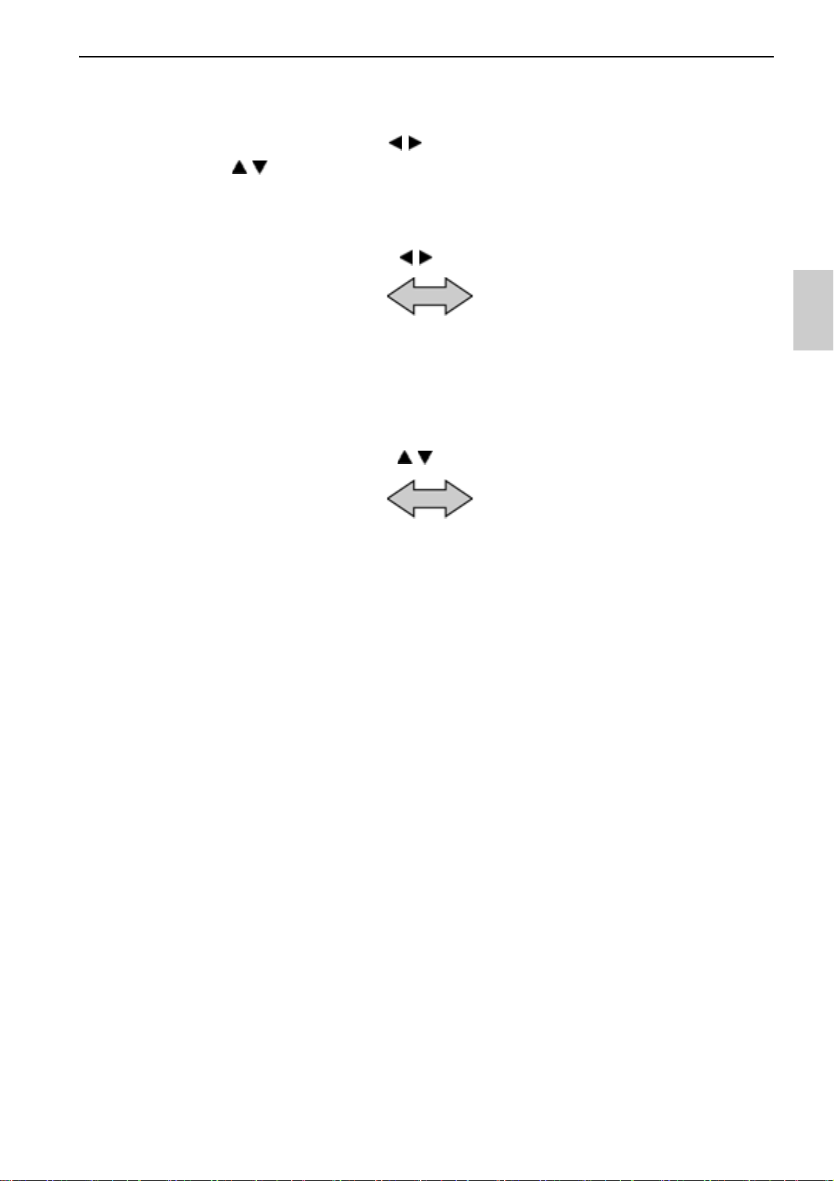
● Entering numeric values
When entering numeric values to make various settings and set a calibration value,
change the selected digit using the keys and increment or decrement the value (0
to 9) using the keys.
13
Basic operation
Note
key
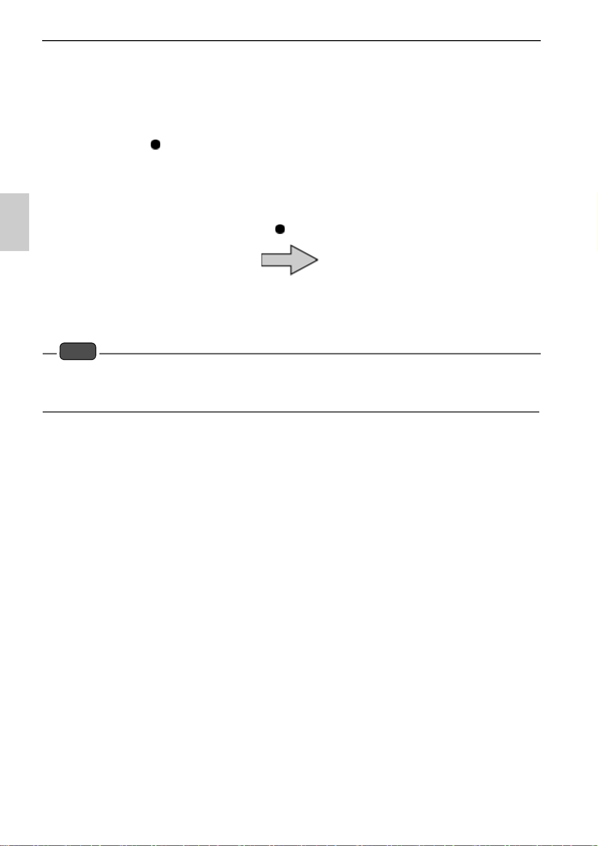
● Saving measurement data in the internal memory
Up to 100 (EC110) or 1000 (EC120) data items measured by the instrument can be
stored in the internal memory. Saving the measurement data is possible only when the
instrument is in the measurement mode.
1. Press the key while the data to save is displayed.
The saved data is displayed for two seconds and then the display returns to the
previous screen automatically.
If the data saved reaches 100 (EC110) or 1000 (EC120) data items, an error occurs and
"ERR No. 0010" is displayed. Copy or transfer necessary data to a PC and delete the data
from the memory ("Deleting all saved data" (page 50)).
14
 Loading...