

HORIBA ABX MICROS ES60, MICROS ESV60 Technical Manual
ABX MICROS ES60/ESV60
Technical Manual
HORIBA ABX SAS
B.P. 7290
34184 MONTPELLIER Cedex 4 - FRANCE
P/n: RAA033AEN

ABX Micros ES60/ESV60
Introduction
Revisions
Index P/n revision Software revision Section Date
A RAN033A V1.1.X All 12/02/09
◆ This document applies to the latest software version as indicated above.
◆ When a subsequent software version changes the information in this manual, a new section and/
or sections will be released.
Notice of liability
◆ The Information in this manual is distributed on an «As Is» basis, without warranty. While every
precaution has been taken in the preparation of this manual, HORIBA Medical will not assume any
liability to any persons or entities with respect to loss or damage, caused or alleged to be caused
directly or indirectly by not following the instructions contained in this manual, or by using the
computer software and hardware products described herein in a manner inconsistent with our
product labeling.
Potential hazards
◆ To alert the operator of potentially hazardous conditions, one of the bold captioned headings
which are described below is provided wherever necessary throughout this text.
Flags a procedure that if not followed properly, can prove to be extremely
hazardous to either the operator or the environment or both.
Emphasizes an operating procedure that must be followed to avoid possible
damage to the instrument or erroneous test results.
Emphasizes important information especially helpful to the operator before,
during or after a specific operational function.
Graphics
◆ All graphics including screens and printouts, photographs are for illustration purposes only and
are not contractual.
Trademarks
◆ Other product names mentioned within this publication may be registered trademarks of other
companies.
Copyright 2009 HORIBA Medical
All rights reserved. No part of this book may be reproduced or transmitted in any form or by any
means, electronic, mechanical, photocopying, recording, or otherwise, without the prior written
permission of HORIBA Medical.
HORIBA Medical
Rue du Caducée - Parc Euromédecine
34184 MONTPELLIER Cedex 4 - FRANCE
Tel: + 33 (0)4 67 14 15 16
Fax: + 33 (0)4 67 14 15 17
2 - Technical Manual - RAA033AEN

Introduction
1. Operational conditions
1.1. Environment
◆ The operation of the ABX Micros ES60/ESV60 should be restricted to indoor location use only.
Instrument is operational at an altitude of maximum 3000 meters (9840 feet).
◆ The ABX Micros ES60/ESV60 is de s igne d for sa f ety fro m voltage s surge s accord ing to I N S TALLATIO N
CATEGORY II and POLLUTION DEGREE 2 (IEC 61010-1) Please contact your local HORIBA Medical
representative for information regarding operation locations, when it does not comply with the
recommended specifications.
1.2. Location
◆ The ABX Micros ES60/ESV60 should be placed on a clean and leveled table or workbench.
◆ Please note that the instrument, printer and reagents weigh approximately 20 kilograms (44 lbs).
◆ Avoid exposure to sunlight.
◆ Place your instrument in a well-ventilated area.
◆ Place your instrument where it is not exposed to water or vapor.
◆ Place your instrument where it is free from vibration or shock.
◆ Place your instrument where an independent power receptacle can be used.
◆ Use a receptacle different from the one used by a device that easily generate noise such as a
centrifuge, etc...
◆ Provide a space of at least 20 cm (8 inches) at the back of the instrument for arranging the power
cable and tubings.
The power switch and input voltage supply connection should always be
accessible. When positioning the system for operational use, leave the
required amount of space for easy accessibility to these items.
1.3. Grounding
◆ Proper grounding is required when installing the system. Check the wall outlet ground (Earth) for
proper grounding to the facilities electrical ground. If you are unsure of the outlet grounding,
contact your facilities engineer to verify the proper outlet ground.
1.4. Humidity/temperature conditions
◆ The ABX Micros ES60/ESV60 must operate between temperatures of 16°C to 30°C (61°F to 86°F).
◆ Maximum relative humidity 85% for temperature up to 30°C (86°F) without condensation.
◆ If it is stored at a temperature less than 10°C (50°F), the instrument should stand for 1 hour at
the correct room temperature before use.
1.5. Electromagnetic environment check
◆ The ABX Micros ES60/ESV60 has been designed to produce less than the accepted level of
electromagnetic interference in order to operate in conformity with its destination, allowing the
correct operation of other instruments also in conformity with their destination.
◆ In case of suspected electromagnetic noise, check that the instrument has not been placed in the
proximity of electromagnetic fields or short wave emissions, (i. e. Radar, X-rays, Scanners, Cell
phones, etc...).
Technical Manual - RAA033AEN - 3
ABX Micros ES60/ESV60
1.6. Main supply
◆ Grounding is required. Check that the earth wall-plug is correctly connected to the laboratory
grounding system. If there is no such system a ground stake should be used.
◆ Use only main supply cable delivered with the ABX Micros ES60/ESV60.
◆ Main supply voltage fluctuations must not exceed +/-10% of the nominal voltage.
2. Environmental protection
2.1. Disposal used accessories and consumables
◆ Must be collected by a laboratory specialized in elimination and recycling of this kind of material
according to the local legislation.
2.2. Disposal ABX Micros ES60/ESV60 instrument
◆ It should be disposed of, in accordance with local legislation, and should be treated as being
contaminated with blood. The appropriate biological precautions should be taken.
If any doubt, please contact your HORIBA Medical representative service
department.
2.3. European Legislation
In accordance with the European Directive (2002/96/CE, known also as
W.E.E.E) instruments having the above symbol and sold into a European
country by HORIBA Medical or an authorised representative must be disposed
of and recycled correctly at the end of its useful life.
Due to the local changing regulations in each country, please contact your
local representative for detailed and upto date information on how to
appropriately dispose of the instrument.
2.4. Transportation and storage conditions
◆ Condition for storage and transportation: Temperature from -20°C to +65°C (-4°F to 122°F).
Prior to the shipping of an instrument by transporter, whatever the
destination, an external decontamination of the instrument must be carried
out.
4 - Technical Manual - RAA033AEN

Specifications
Section 01: Specific ations
1. Specifications ................................................................................................... S01-2
1.1. Parameters................................................................................................S01-2
1.2. Instrument specifications ..........................................................................S01-3
1.3. Technical specifications............................................................................S01-3
2. Description ...................................................................................................... S01-4
2.1. Overview..................................................................................................S01-4
2.1.1. ABX Micros ES60 CT ........................................................................S01-4
2.1.2. ABX Micros ES60 OT........................................................................ S01-4
2.2. Front view (covers opened) ....................................................................... S01-4
2.2.1. ABX Micros ES60 CT ........................................................................S01-4
2.2.2. ABX Micros ES60 OT........................................................................ S01-5
2.3. Left side view (covers opened) .................................................................. S01-5
2.4. Rear view .................................................................................................S01-5
Technical Manual - RAA033AEN - S01 / 1
ABX Micros ES60/ESV60
1. Specifications
1.1. Parameters
- 16 parameters
Parameter Definition
WBC White blood cells
LYM% Lymphocyte Percentage
LYM# Lymphocyte Absolute number
MON% Monocyte Percentage
MON# Monocyte Absolute number
GRA% Granulocyte Percentage
GRA# Granulocyte Absolute number
RBC Red blood cells
HGB Hemoglobin
HCT Hematocrit
MCV Mean Corpuscular Volume
MCH Mean Corpuscular Hemoglobin
MCHC Mean Corpuscular Hemoglobin Concentration
RDW Red cell Distribution Width
PLT Platelets
MPV Mean Platelet Volume
WBC, RBC and PLT Distribution Curves
- 18 parameters
Parameter Definition
WBC White blood cells
LYM% Lymphocyte Percentage
LYM# Lymphocyte Absolute number
MON% Monocyte Percentage
MON# Monocyte Absolute number
GRA% Granulocyte Percentage
GRA# Granulocyte Absolute number
RBC Red blood cells
HGB Hemoglobin
HCT Hematocrit
MCV Mean Corpuscular Volume
MCH Mean Corpuscular Hemoglobin
MCHC Mean Corpuscular Hemoglobin Concentration
RDW Red cell Distribution Width
PLT Platelets
MPV Mean Platelet Volume
PDW* Platelet Distribution Width
PCT* Plateletcrit
WBC, RBC and PLT Distribution Curves
*PDW and PCT have not been established as indications for this product, in
the United States. The use of PDW and PCT should be restricted to Research
Use Only.
S01 / 2 - Technical Manual - RAA033AEN

1.2. Instrument specifications
ABX MICROS ES60 (OT/CT)/ ABX MICROS ESV60 (OT)
Approximately 60 Samples/hour for the ABX Micros ES60 OT, 50
Throughput analysis
Minimum sample volume
Dilution ratios
Measurements and
Computation
Counting Aperture Diameter WBC: 80µm / RBC: 50µm.
Hemoglobin Measurement
Statistics and Quality Control Extended Quality Control package.
Calibration
Reagents
Wastes
Samples/hour for the ABX Micros ES60 CT and 50 Samples /hour for
the ABX Micros ESV60.
Minimum blood sample requirement 50µl
Analyzer sample volume 10µl
WBC Approximately 1/260 for ABX Micros ES60 and 1/255 for ABX
Micros ESV60
RBC/PLT Approximately 1/15000
Impedance change for WBC, RBC, PLT.
Spectrophotometry for HGB.
Impedance change for LYM%, MON%, GRA%.
Computation from stored Data that was directly measured for MCV,
MCH, MCHC, RDW, MPV, LYM#, MON#, GRA#.
Performed in the WBC/HGB Chamber.
Light source LED (Light Emiting Diode) at wavelength 550nm.
Automatic Calibration procedure.
Direct entering of Calibration Coefficients.
ABX Micros ES60:
3 Reagents or 1 Pack of Reagents:
Diluent: ABX Minidil LMG (10L)
Cleaner: ABX Miniclean (1L) or ABX Cleaner (0.5L)
Lyse: ABX Minilyse LMG (1L), ABX Alphalyse (0.4L) or ABX
Alphalyse 360 (0.36L)
Pack all reagents: ABX Minipack LMG (4.2L)
ABX Micros ESV60: ABX VetPack
Automatic disposal
Waste handling according to Local/National regulations
Specifications
1.3. Technical specifications
ABX MICROS ES60 (OT/CT)/ ABX MICROS ESV60 (OT)
Software Designed by HORIBA Medical, Installed on a Flash EPROM
Memory capacity 1000 results
Display Operated touch screen, LVDS Screen: 8’’4, 640x480, 256000 colours
Outputs
Barcode reader
Internal ticket printer ABX Micros ES60 only
Power requirements
Dimensions
Weight Weight Approximately 17Kgs (37.5 lbs)
Hard Copy printing (Internal or external printer)
External output (RS232)
C 39, C 128, ITF (2of5), CODABAR, ISBT C128 (for ABX Micros ES60
CT only).
(External barcode reader optional for ABX Micros ES60)
Power supply 100V, 240V (+/- 10%) 50/60Hz.
Power Consumption
Maximum: 150VA (-30%, +10%)
In use: 100VA (-30%, +10%)
Stand-by mode: 35 VA (-30%, +10%)
Heat output 197Kj/h (187BTU/h)
Height Approximately 430mm (16.9 inches)
Width Approximately 360mm (14.2 inches)
Depth Approximately 360mm (14.2 inches)
Technical Manual - RAA033AEN - S01 / 3
ABX Micros ES60/ESV60
2. Description
2.1. Overview
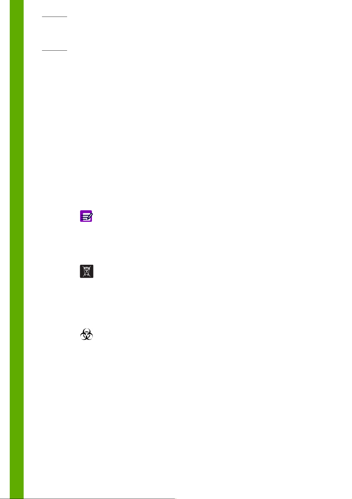
2.1.1. ABX Micros ES60 CT
4
1
3
2
5
6
1- LCD display touchscreen
2- Cap piercing mechanism & Tube Holder
3- Reagent compartment
4- Printer
5- Barcode reader
6- USB port
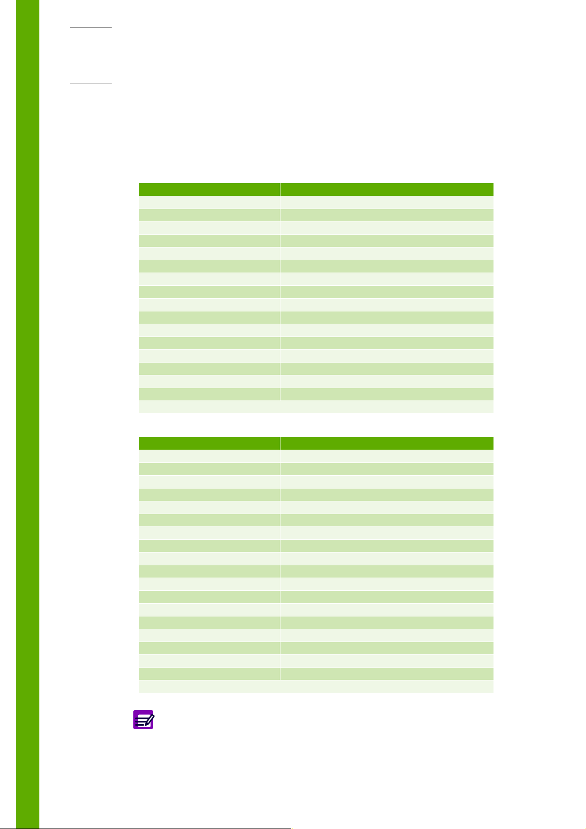
2.1.2. ABX Micros ES60 OT
4
1
3
2
5
2.2. Front view (covers opened)
2.2.1. ABX Micros ES60 CT
1
4
3
1- LCD display & touchscreen
2- Manual sampling needle
3- Reagent compartment
4- Printer
5- USB port
1- Carriage assembly
2- Tube holder
3- WBC/HGB chamber
4- RBC chamber
2
S01 / 4 - Technical Manual - RAA033AEN
2.2.2. ABX Micros ES60 OT
1
1- Carriage assembly
4
3
2
2- Sampling needle and analysis start bar
3- WBC/HGB chamber
4- RBC chamber
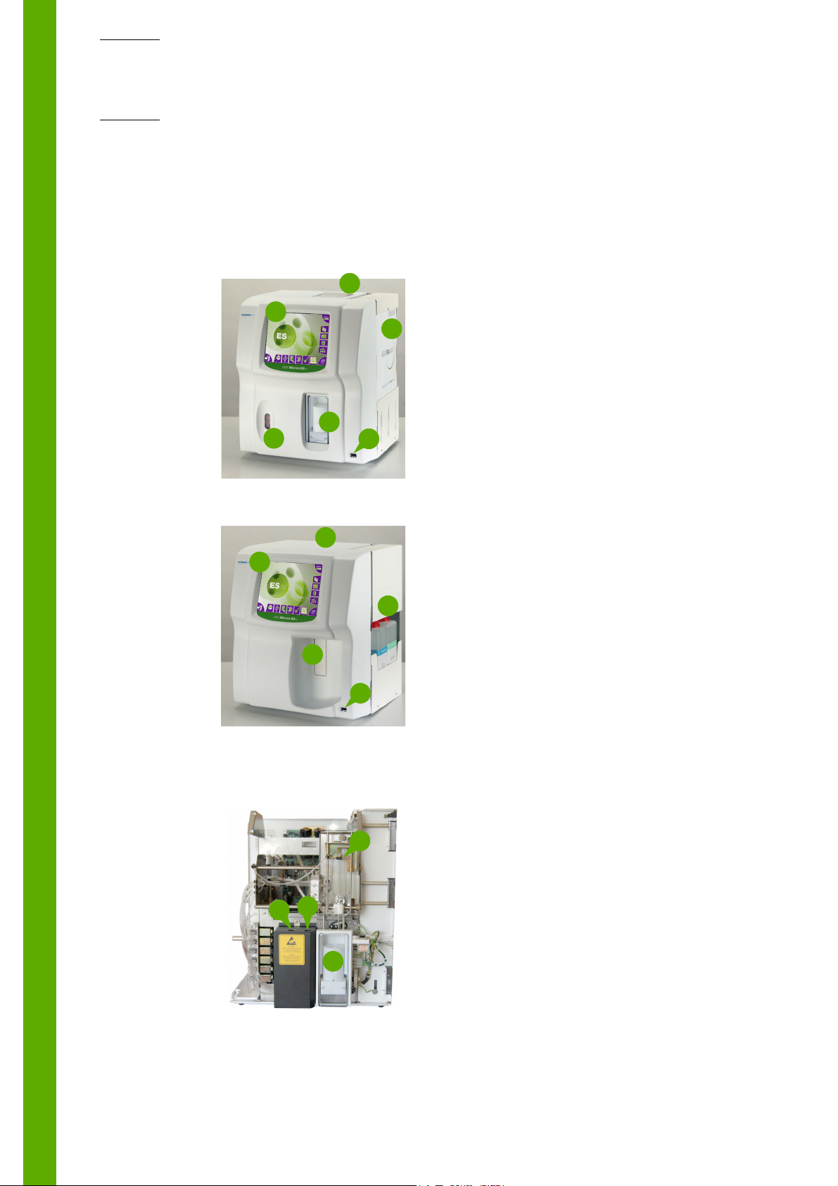
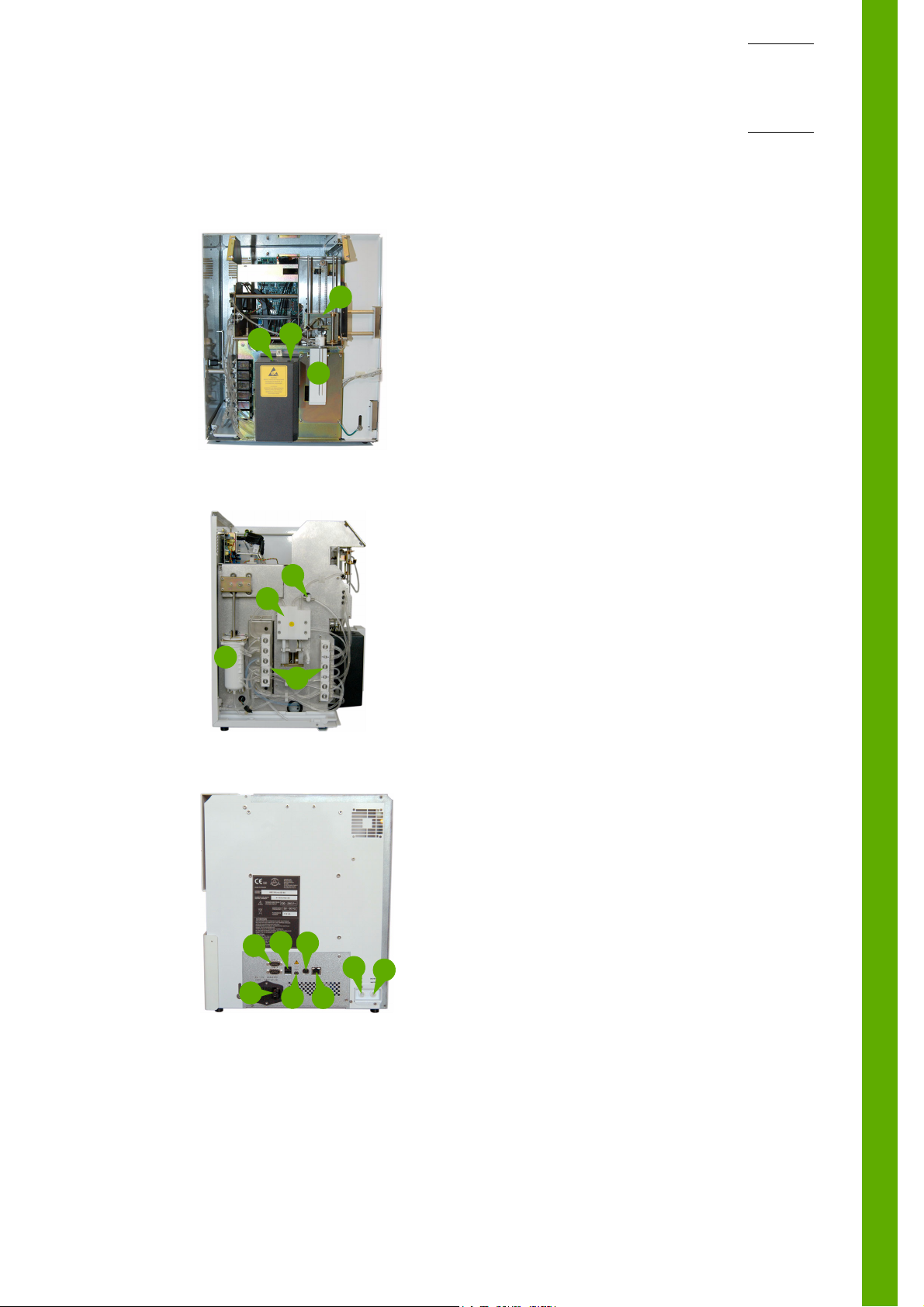
2.3. Left side view (covers opened)
Specifications
4
2.4. Rear view
1
6
1
2
3
2
4
7
8
3
5
1- Diluent temperature sensor
2- Liquid syringe
3- Valve blocks
4- Vacuum/waste syringe
1- 2 RS232 ports
2- 2 USB ports
3- 1 Jack connector: not functional
4- 1 PS2 ports
5- 1 RJ45 port
6- 1 power supply
7- 1 Diluent input connector
8- 1 Waste output connector
Technical Manual - RAA033AEN - S01 / 5

ABX Micros ES60/ESV60
S01 / 6 - Technical Manual - RAA033AEN

Hydraulic & pneumatic principles
Section 02: Hydraulic & pneumatic principles
1. Generalities...................................................................................................... S02-2
2. ABX Micros ES60 OT hydraulic........................................................................ S02-3
2.1. Tubes list ..................................................................................................S02-3
2.2. Function of valves.....................................................................................S02-3
2.3. Hydraulic cycle description ...................................................................... S02-4
2.3.1. Atmosphere circuit ........................................................................... S02-4
2.3.2. Diluent circuit .................................................................................. S02-5
2.3.3. Clean circuit .....................................................................................S02-6
2.3.4. Lyse circuit .......................................................................................S02-7
2.3.5. WBC / RBC counting circuit ............................................................. S02-8
2.3.6. Drain / bubbling circuit .................................................................... S02-9
3. ABX Micros ES60 CT hydraulic ......................................................................S02-10
3.1. Tubes list ................................................................................................S02-10
3.2. Function of valves...................................................................................S02-10
3.3. Hydraulic cycle description .................................................................... S02-11
3.3.1. Atmosphere circuit ......................................................................... S02-11
3.3.2. Diluent circuit ................................................................................ S02-12
3.3.3. Clean circuit ...................................................................................S02-13
3.3.4. Lyse circuit ..................................................................................... S02-14
3.3.5. WBC / RBC counting circuit ........................................................... S02-15
3.3.6. Drain / bubbling circuit .................................................................. S02-16
4. Pneumatic diagrams .......................................................................................S02-17
4.1. ABX Micros ES60 CT bottle version ........................................................S02-17
4.2. ABX Micros ES60 CT pack version.......................................................... S02-17
4.3. ABX Micros ES60 OT bottle version........................................................ S02-17
4.4. ABX Micros ES60 OT pack version ......................................................... S02-17
Technical Manual - RAA033AEN - S02 / 1
ABX Micros ES60/ESV60
1. Generalities
◆ The ABX Micros ES60/ESV60 instrument has been designed for simple mechanical operations.
◆ 4 stepper motors provide movements to mechanical assemblies.
◆ Pressure and vacuum are provided by the vacuum/waste syringe up and down movements (A).
◆ Liquid movements are achieved either by means of mechanical assembly movements (B) or by
pressure/vacuum syringe and simultaneous action of specific valves.
B
A
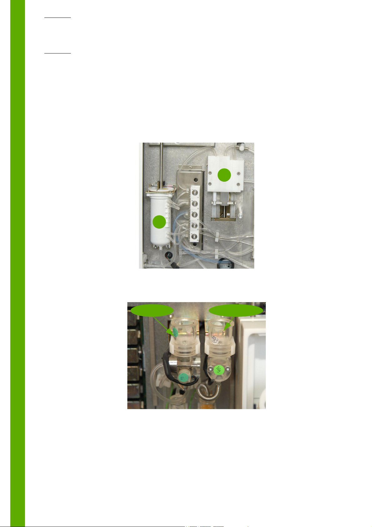
◆ Dilution chambers
The diode and the cell of the spectrophotometer are glued on the WBC/HGB chamber.
Chamber positions can be modified in order to obtain the best sampling position possible.
WBC chamber
RBC/PLT chamber
◆ Dilutions:
First dilution is carried out in the WBC/HGB chamber (with a bubbling phasis).
The RBC blood sample is aspirated from this dilution.
Lyse is sent from the drain nipple of the WBC/HGB chamber.
◆Rinse:
To obtain the best rinse in the counting heads, diluent is sent from the liquid syringes. This is
carried out before, between and after the two counts.
S02 / 2 - Technical Manual - RAA033AEN
Hydraulic & pneumatic principles
A window on the HGB/WBC chamber allows the needle to move down into the
chamber and to inject reagents. As important light or variation of light can
cause HGB result drifts, close instrument cover and door before running blood
analyses.
◆ Bubbling:
Insulators avoid polluted liquid overflows during bubbling phasis. They also allows an accurate
adjustment of the bubbling volume.
◆ ABX Micros ES60 CT specifics:
- The piercing needle is equipped with two injectors to obtain a homogeneous diluent flow during
needle rinsing phasis (see procedures RAS188A and RAS187A).
- Atmosphere is provided to sample tubes to allow a correct aspiration of blood.
2. ABX Micros ES60 OT hydraulic
2.1. Tubes list
DESIGNATION PART NUMBER DIAMETER
SLEEVE HPS3 DBD005A 5-9
T CONNECTOR EAB006B 2.3
T CONNECTOR EAB032A 1.5
TUBE CAP EAC017A 2.5
TYGON TUBE 0.051" EAE006A 1.30
TYGON TUBE 0.060" EAE007A 1.52
TYGON TUBE 0.081" EAE008A 2.05
TYGON TUBE 0.090" EAE009A 2.28
SLEEVE GAL098A
TUBE SHIELD GBC088A 4.4
GROUND FITTING GAA162A
METALLIC SHEATH (Pack model only) GBC170A 5.2
TEFFLON TUBE (2 meter) EAE061AS 1.32x1.93
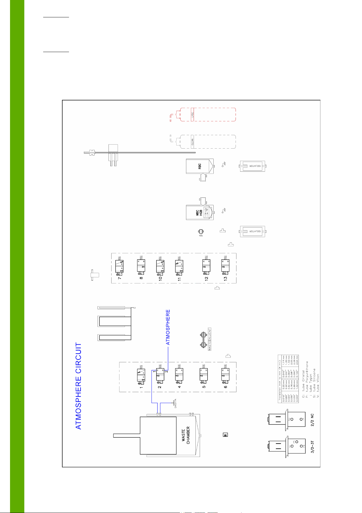
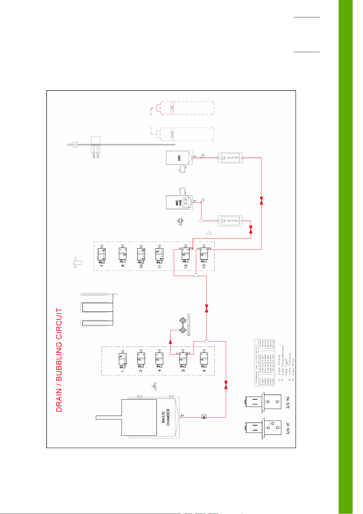
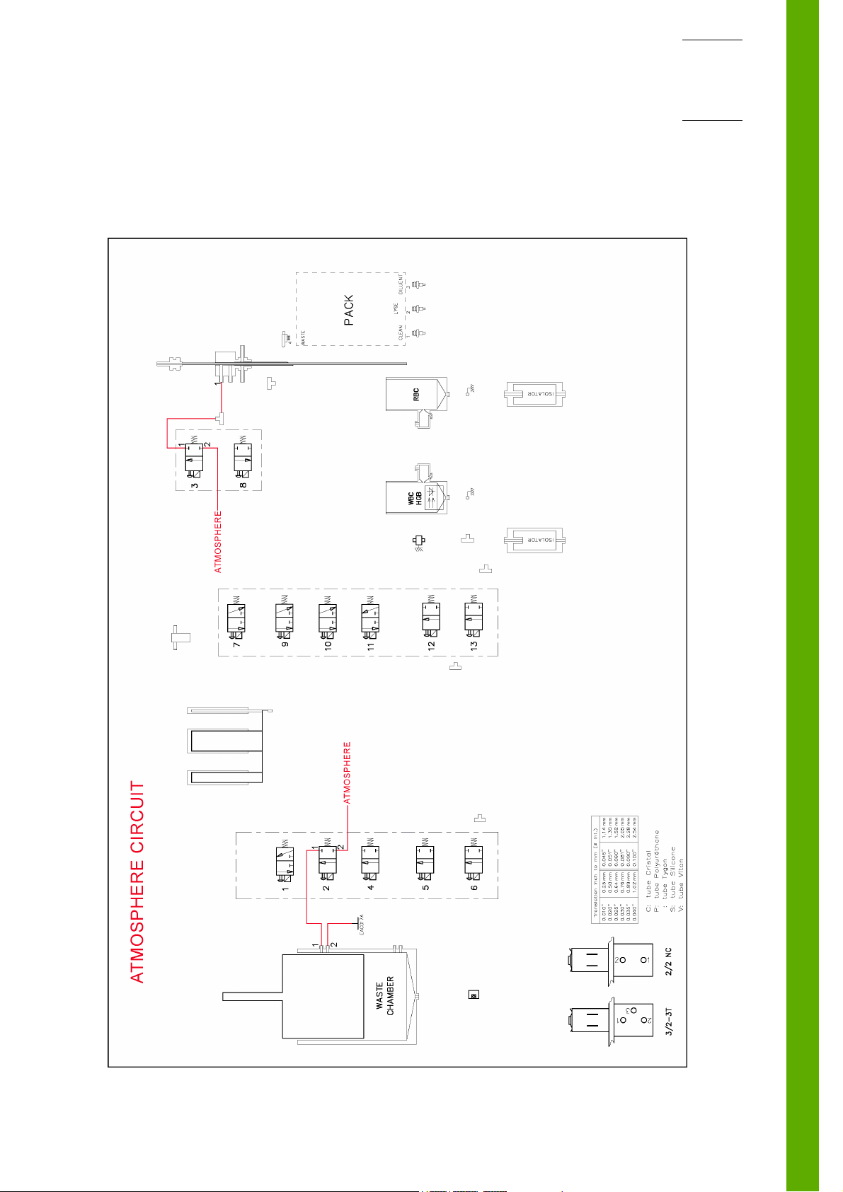
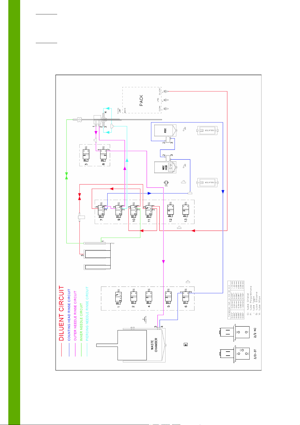
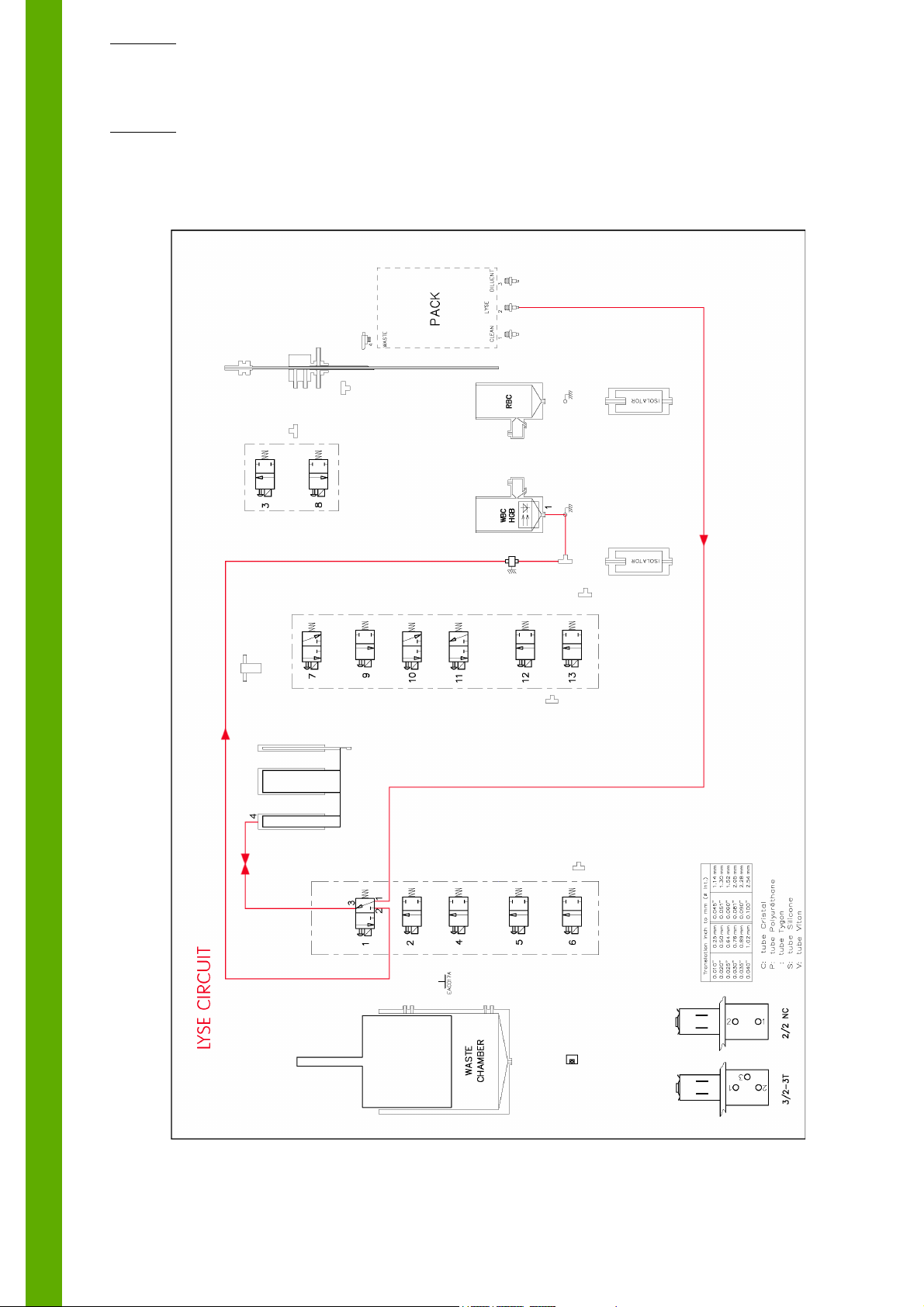
2.2. Function of valves
Valve number Functions
1 Controls the lyse distribution
2 Cancels the pressure/vacuum in the pressure/vacuum syringe
4 Controls the cleaner input in the WBC counting head during the rinsing
5 Controls the drain of the pressure/vacuum syringe
6 Activates the vacuum needed in the WBC/RBC counting heads
7 Controls the diluent input in the RBC counting head during the rinsing
8 Controls the aspiration of the diluent/air input inside the needle rinse block
10 Controls the diluent inside the aspiration needle
11 Controls the diluent distribution
12 Controls the drain of the WBC chamber
13 Controls the drain of the RBC chamber
Technical Manual - RAA033AEN - S02 / 3
ABX Micros ES60/ESV60
2.3. Hydraulic cycle description
2.3.1. Atmosphere circuit
S02 / 4 - Technical Manual - RAA033AEN
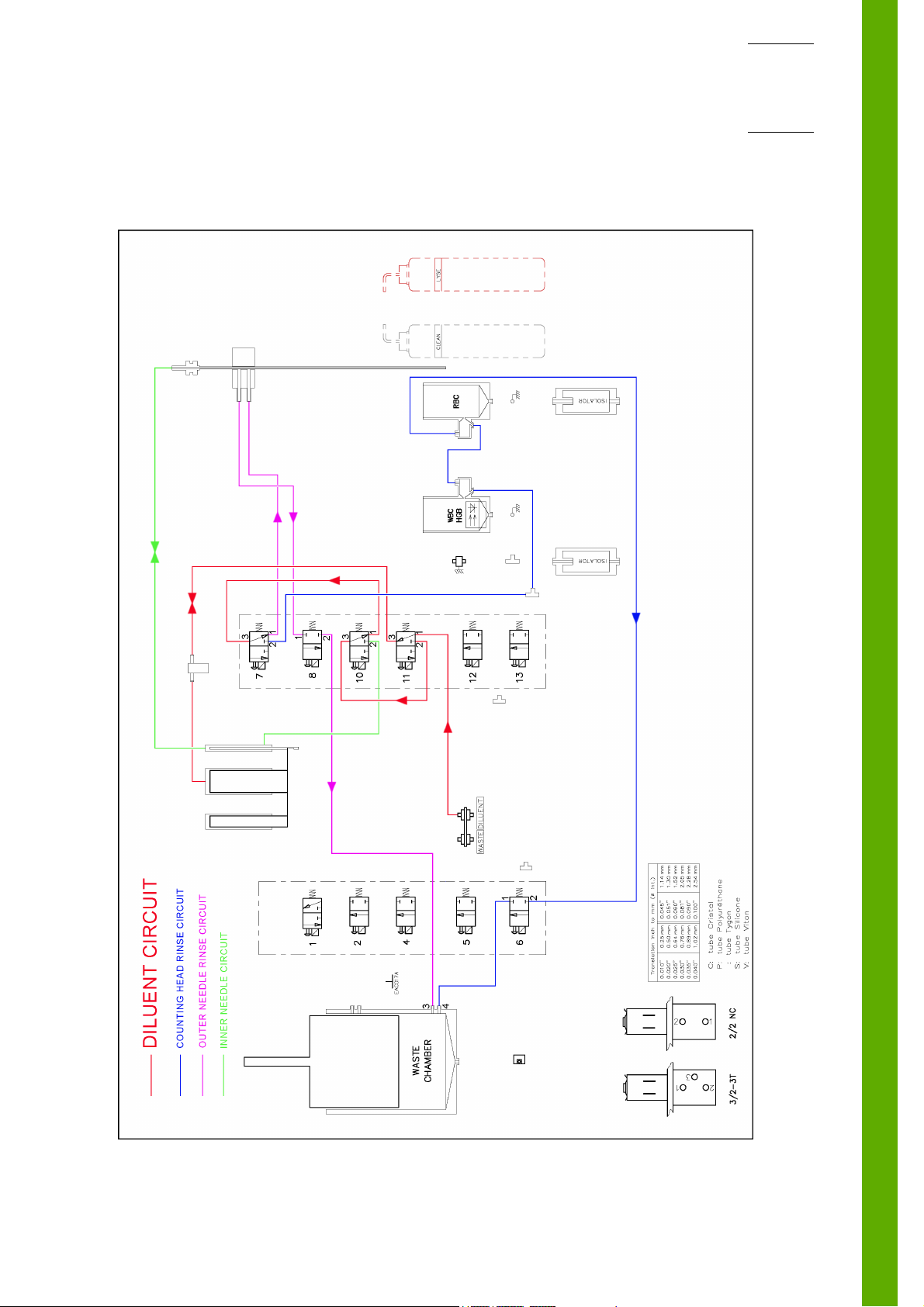
2.3.2. Diluent circuit
Hydraulic & pneumatic principles
Technical Manual - RAA033AEN - S02 / 5
ABX Micros ES60/ESV60
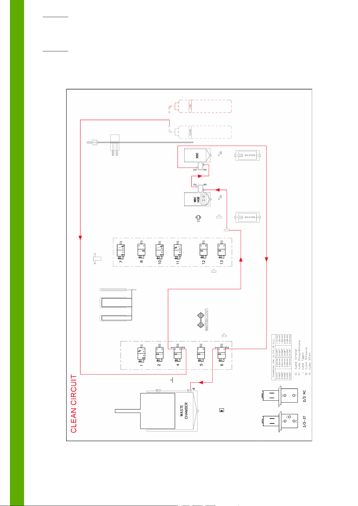
2.3.3. Clean circuit
S02 / 6 - Technical Manual - RAA033AEN
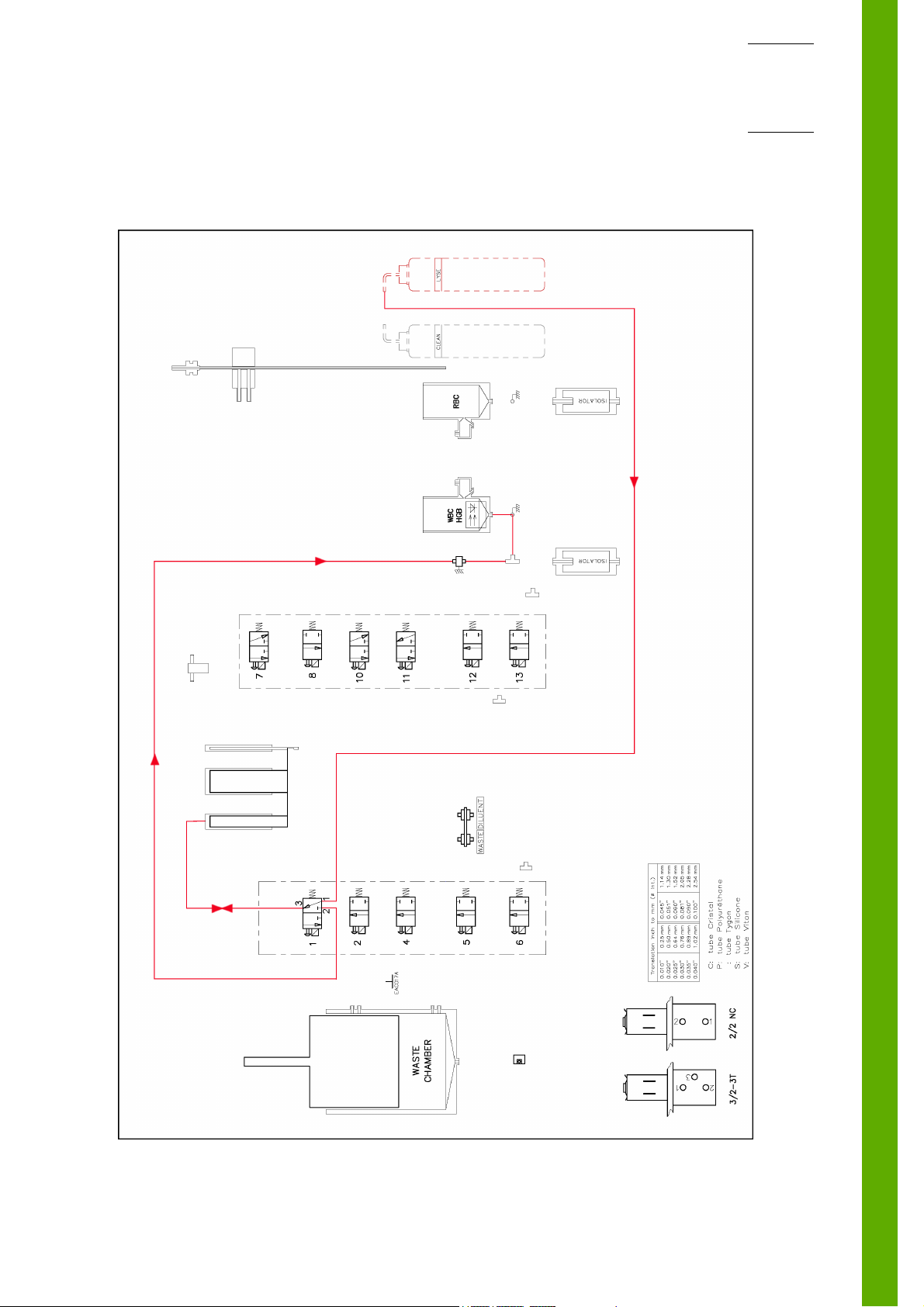
2.3.4. Lyse circuit
Hydraulic & pneumatic principles
Technical Manual - RAA033AEN - S02 / 7
ABX Micros ES60/ESV60
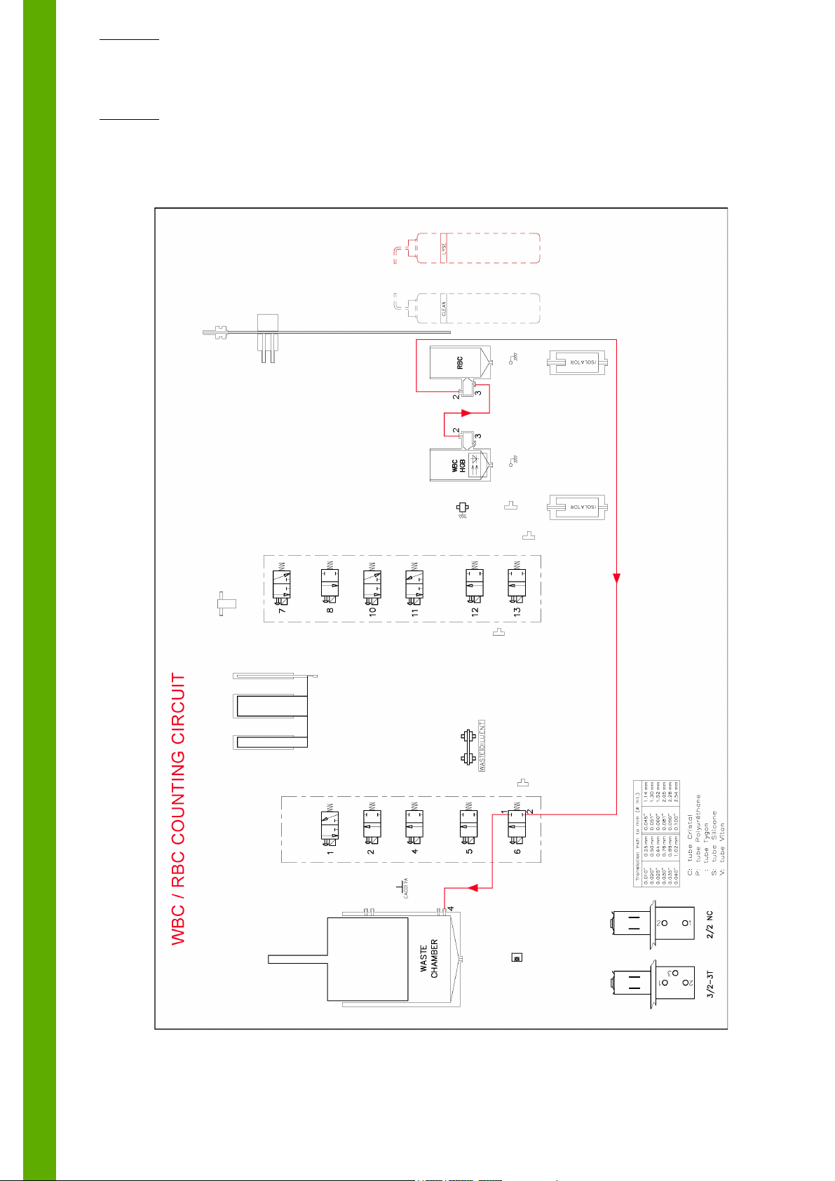
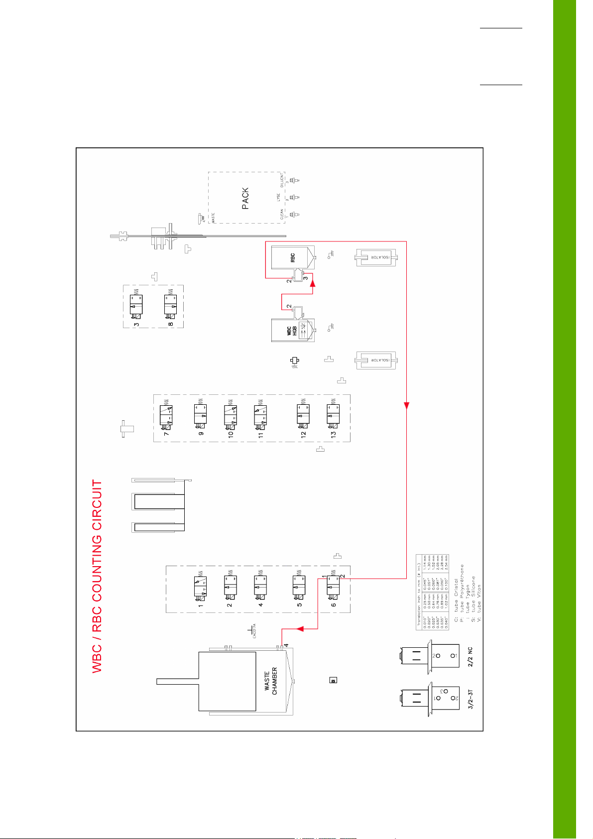
2.3.5. WBC / RBC counting circuit
S02 / 8 - Technical Manual - RAA033AEN
Hydraulic & pneumatic principles
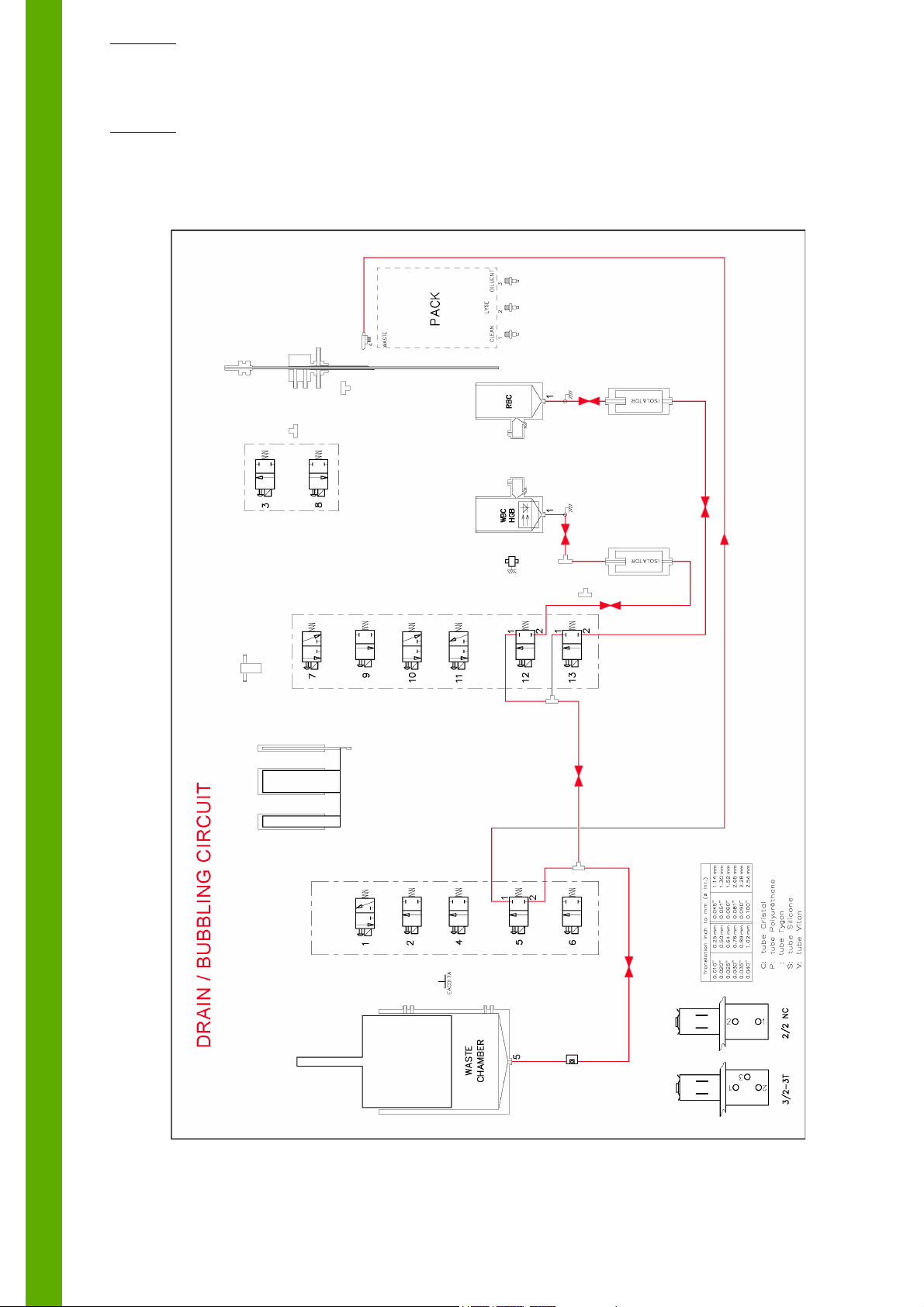
2.3.6. Drain / bubbling circuit
Technical Manual - RAA033AEN - S02 / 9

ABX Micros ES60/ESV60
3. ABX Micros ES60 CT hydraulic
3.1. Tubes list
DESIGNATION PART NUMBER DIAMETER
T CONNECTOR EAB006B 2.3
STRAIGHT CONNECTOR EAB015B 1.5/2.5
T CONNECTOR EAB032A 1.5
TUBE CAP EAC017A 2.5
TYGON TUBE 0.040" EAE005A 1.02
TYGON TUBE 0.060" EAE007A 1.52
TYGON TUBE 0.081" EAE008A 2.05
TYGON TUBE 0.090" EAE009A 2.28
SILICON TUBE EAE025A 1.5/3.5
SLEEVE GAL098A
TUBE SHIELD GBC088A 4.4
GROUND FITTING GAA162A
METALLIC SHEATH (Pack model only) GBC170A 5.2
3.2. Function of valves
Valve number Functions
1 Controls the lyse distribution
2 Cancels the pressure/vacuum in the pressure/vacuum syringe
3 Air input inside the needle rinse block
4 Controls the cleaner input in the WBC counting head during the rinsing
5 Controls the drain of the pressure/vacuum syringe
6 Activates the vacuum needed in the WBC/RBC counting heads
7 Controls the diluent input in the RBC counting head during the rinsing
8 Controls the aspiration of the diluent/air input inside the needle rinse block
9 Routes the diluent distribution to the inside or outside of the piercing needle
10 Controls the diluent inside the aspiration needle
11 Controls the diluent distribution
12 Controls the drain of the WBC chamber
13 Controls the drain of the RBC chamber
S02 / 10 - Technical Manual - RAA033AEN
Hydraulic & pneumatic principles
3.3. Hydraulic cycle description
3.3.1. Atmosphere circuit
Technical Manual - RAA033AEN - S02 / 11
ABX Micros ES60/ESV60
3.3.2. Diluent circuit
S02 / 12 - Technical Manual - RAA033AEN

3.3.3. Clean circuit
Hydraulic & pneumatic principles
Technical Manual - RAA033AEN - S02 / 13
ABX Micros ES60/ESV60
3.3.4. Lyse circuit
S02 / 14 - Technical Manual - RAA033AEN
Hydraulic & pneumatic principles
3.3.5. WBC / RBC counting circuit
Technical Manual - RAA033AEN - S02 / 15
ABX Micros ES60/ESV60
3.3.6. Drain / bubbling circuit
S02 / 16 - Technical Manual - RAA033AEN

Hydraulic & pneumatic principles
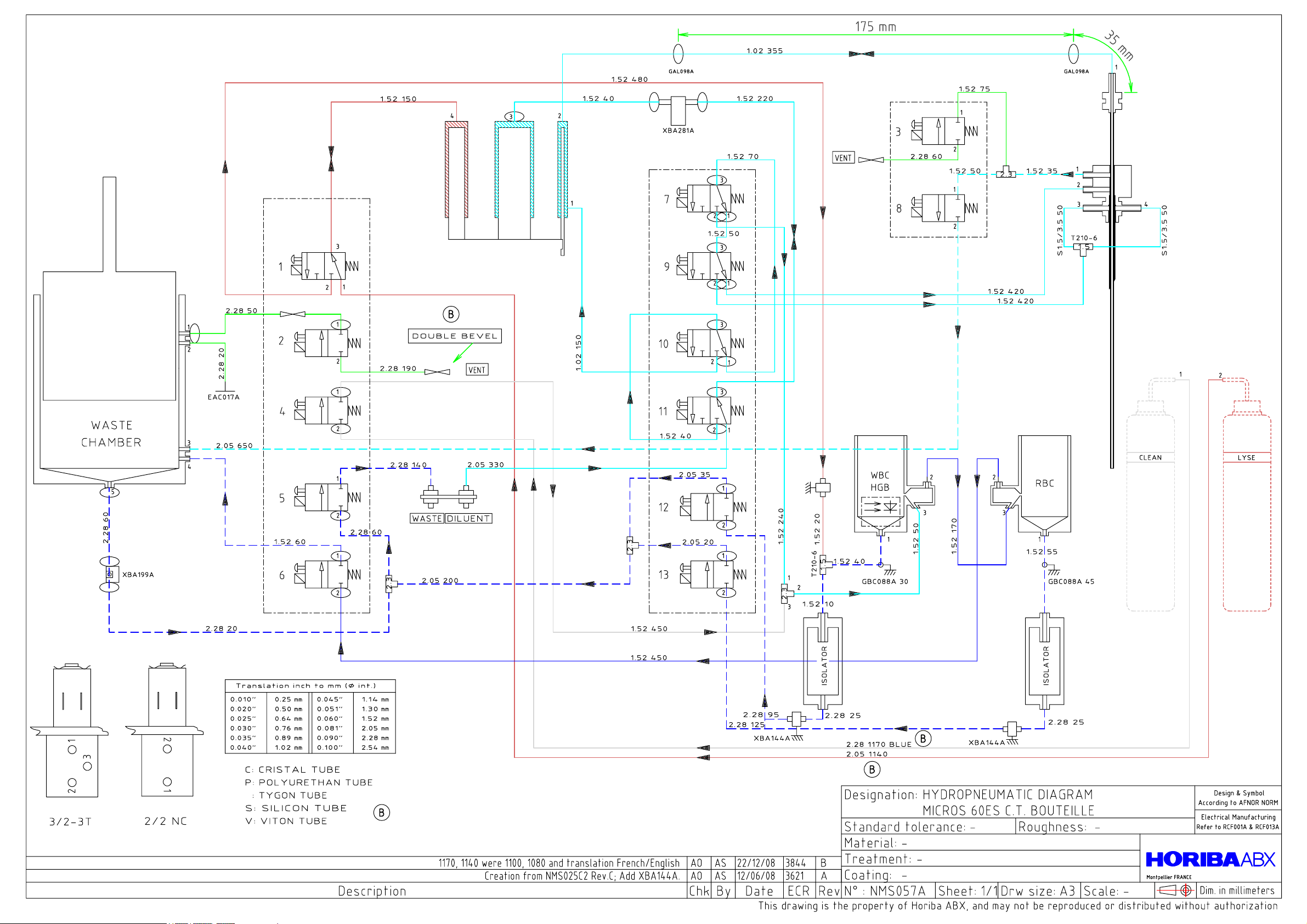
4. Pneumatic diagrams
4.1. ABX Micros ES60 CT bottle version
see following pages
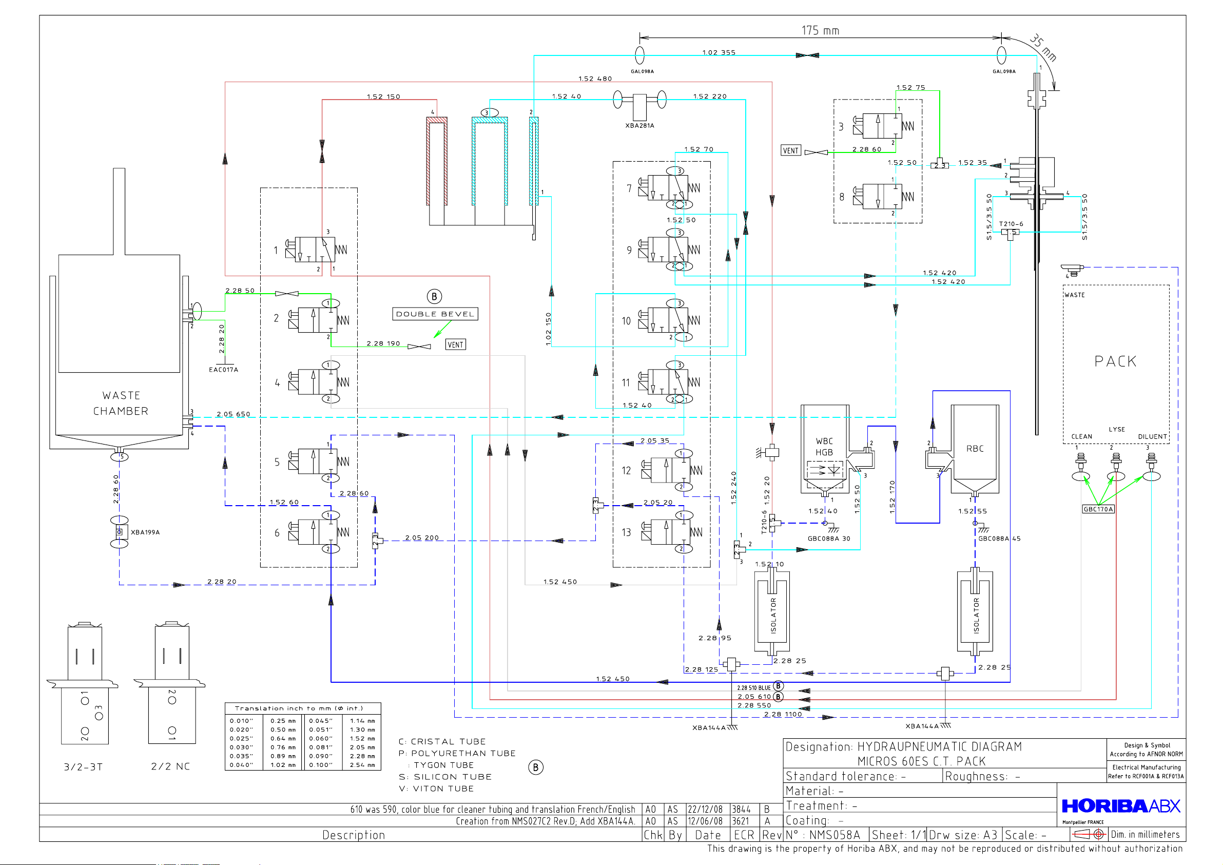
4.2. ABX Micros ES60 CT pack version
see following pages
4.3. ABX Micros ES60 OT bottle version
see following pages
4.4. ABX Micros ES60 OT pack version
see following pages
Technical Manual - RAA033AEN - S02 / 17

ABX Micros ES60/ESV60
S02 / 18 - Technical Manual - RAA033AEN
 Loading...