

HORIBA APOA-370 Operation Manual

Ambient O3 monitor
APOA-370
Operation Manual
CODE:GZ0000051248C

Preface
This manual describes the operation of the Ambient O3 monitor, APOA-370.
Be sure to read this manual before using the product to ensure proper and safe operation of
the instrument. Also safely store the manual so it is readily available whenever necessary.
Product specifications and appearance, as well as the contents of this manual are subject to
change without notice.
■ Warranty and Responsibility
HORIBA warrants that the Product shall be free from defects in material and workmanship
and agrees to repair or replace free of charge, at HORIBA’s option, any malfunctioned or
damaged Product attributable to HORIBA’s responsibility for a period of one (1) year from the
delivery unless otherwise agreed with a written agreement. In any one of the following cases,
none of the warranties set forth herein shall be extended;
z
Any malfunction or damage attributable to improper operation
z
Any malfunction attributable to repair or modification by any person not authorized by
HORIBA
z
Any malfunction or damage attributable to the use in an environment not specified in this
manual
z
Any malfunction or damage attributable to violation of the instructions in this manual or
operations in the manner not specified in this manual
z
Any malfunction or damage attributable to any cause or causes beyond the reasonable
control of HORIBA such as natural disasters
z
Any deterioration in appearance attributable to corrosion, rust, and so on
z
Replacement of consumables
HORIBA SHALL NOT BE LIABLE FOR ANY DAMAGES RESULTING FROM ANY
MALFUNCTIONS OF THE PRODUCT, ANY ERASURE OF DATA, OR ANY OTHER USES
OF THE PRODUCT.
■ Trademarks
Generally, company names and brand names are either registered trademarks or trademarks
of the respective companies.
February, 2009 © 2004 − 2009 HORIBA, Ltd.
Conformable Directive
This equipment conforms to the following directives and standards:
Directives:
Standards:
the EMC Directive 2004/108/EC
the Low Voltage Directive 2006/95/EC
[the EMC Directive] EN61326-1: 2006
EMI Class B, EMS: Industry
[the Low Voltage Directive] EN61010-1: 2001
● Installation Environment
This product is designed for the following environment.
z
Installation Categories II
z
Pollution degree 2
● Information on Disposal of Electrical and Electronic Equipment
and Disposal of Batteries and Accumulators
The crossed out wheeled bin symbol with underbar shown on the product or accompanying
documents indicates the product requires appropriate treatment, collection and recycle for
waste electrical and electronic equipment (WEEE) under the Directive 2002/96/EC, and/or
waste batteries and accumulators under the Directive 2006/66/EC in the European Union.
The symbol might be put with one of the chemical symbols below. In this case, it satisfies the
requirements of the Directive 2006/66/EC for the object chemical.
This product should not be disposed of as unsorted household waste.
Your correct disposal of WEEE, waste batteries and accumulators will contribute to reducing
wasteful consumption of natural resources, and protecting human health and the environment
from potential negative effects caused by hazardous substance in products.
Contact your supplier for information on applicable disposal methods.

FCC Rules
Any changes or modifications not expressly approved by the party responsible for compliance
shall void the user's authority to operate the equipment.
■ Note
This equipment has been tested and found to comply with the limits for a Class B digital
device, pursuant to part 15 of the FCC Rules. These limits are designed to provide reasonable
protection against harmful interference in a residential installation. This equipment generates,
uses, and can radiate radio frequency energy and, if not installed and used in accordance with
the instructions, may cause harmful interference to radio communications. However, there is
no guarantee that interference will not occur in a particular installation. If this equipment does
cause harmful interference to radio or television reception, which can be determined by turning the equipment off and on, the user is encouraged to try to correct the interference by one
or more of the following measures:
z
Reorient or relocate the receiving antenna.
z
Increase the separation between the equipment and receiver.
z
Connect the equipment into an outlet on a circuit different from that to which the receiver
is connected.
z
Consult the dealer or an experienced radio/TV technician for help.
For your safety
Warning messages are described in the following manner. Read the messages and follow the
instructions carefully.
● Meaning of warning messages
This indicates an imminently hazardous situation which, if not avoided, will
result in death or serious injury. This signal word is to be limited to the most
extreme situations.
This indicates a potentially hazardous situation which, if not avoided, could
result in death or serious injury.
This indicates a potentially hazardous situation which, if not avoided, may
result in minor or moderate injury. It may also be used to alert against
unsafe practices.
Without safety alert indication of hazardous situation which, if not avoided,
could result in property damage.
● Symbols
Description of what should be done, or what should be followed
Description of what should never be done, or what is prohibited
■ Safety Precautions
This section provides precautions to enable you to use the product safely and correctly and to
prevent injury and damage. The terms of DANGER, WARNING, and CAUTION indicate the
degree of imminency and hazardous situation. Read the precautions carefully as it contains
important safety messages.
WARNING
HOT COMPONENT
Hot parts inside can burn you.
Disconnect power before opening cover and wait for component cool down.
ELECTRICAL
Opening the cover while powered on could result in electric shock.
Be sure to turn OFF power prior to opening the cover.
Maintain ground to avoid electric shock.
Disposal of the product
When disposing of the product, follow the related laws and/or regulations of your country for
disposal of the product.
Description in this manual
Note
This interprets the necessary points for correct operation and notifies the important points for
handling the unit.
Reference
This indicates the part of where to refer the information.
Tip
This indicates reference information.

Contents
1 OVERVIEW . . . . . . . . . . . . . . . . . . . . . . . . . . . . . . . . . . . . . . . 1
1.1 Introduction . . . . . . . . . . . . . . . . . . . . . . . . . . . . . . . . . . . . . . . . . . 1
1.2 System Configuration . . . . . . . . . . . . . . . . . . . . . . . . . . . . . . . . . . 1
1.3 Part Names . . . . . . . . . . . . . . . . . . . . . . . . . . . . . . . . . . . . . . . . . . 2
1.3.1 Front panel . . . . . . . . . . . . . . . . . . . . . . . . . . . . . . . . . . . . . . . . . . . . 2
1.3.2 Rear panel . . . . . . . . . . . . . . . . . . . . . . . . . . . . . . . . . . . . . . . . . . . . . 3
2 BASIC OPERATIONS . . . . . . . . . . . . . . . . . . . . . . . . . . . . . . . 4
2.1 Start-up (Measurement Start) . . . . . . . . . . . . . . . . . . . . . . . . . . . . 4
2.2 Shutdown . . . . . . . . . . . . . . . . . . . . . . . . . . . . . . . . . . . . . . . . . . . 5
2.3 Basic Operation Flow . . . . . . . . . . . . . . . . . . . . . . . . . . . . . . . . . . 6
3 MEAS. SCREEN (BASIC SCREEN) . . . . . . . . . . . . . . . . . . . . 7
4 CALIBRATION . . . . . . . . . . . . . . . . . . . . . . . . . . . . . . . . . . . . 11
4.1 Calibration-related Screens . . . . . . . . . . . . . . . . . . . . . . . . . . . . . 11
4.1.1 CAL. screen . . . . . . . . . . . . . . . . . . . . . . . . . . . . . . . . . . . . . . . . . . . . 11
4.1.2 MODE screen . . . . . . . . . . . . . . . . . . . . . . . . . . . . . . . . . . . . . . . . . . 12
4.1.3 Screens for value setting . . . . . . . . . . . . . . . . . . . . . . . . . . . . . . . . . . 13
4.2 Preparation for Calibration . . . . . . . . . . . . . . . . . . . . . . . . . . . . . . 14
4.2.1 Entering the span gas concentration value . . . . . . . . . . . . . . . . . . . . 14
4.3 Automatic Calibration (AIC) . . . . . . . . . . . . . . . . . . . . . . . . . . . . . 16
4.3.1 AIC setting . . . . . . . . . . . . . . . . . . . . . . . . . . . . . . . . . . . . . . . . . . . . . 16
4.3.2 Precautions in setting the AIC sequence . . . . . . . . . . . . . . . . . . . . . . 21
4.3.3 Setting the AIC sequence . . . . . . . . . . . . . . . . . . . . . . . . . . . . . . . . . 22
4.3.4 Starting the AIC sequence with the [AIC] key . . . . . . . . . . . . . . . . . . 25
4.4 Manual Calibration . . . . . . . . . . . . . . . . . . . . . . . . . . . . . . . . . . . . 26
4.4.1 Operational flow . . . . . . . . . . . . . . . . . . . . . . . . . . . . . . . . . . . . . . . . . 26
4.4.2 Zero calibration . . . . . . . . . . . . . . . . . . . . . . . . . . . . . . . . . . . . . . . . . 27
4.4.3 Span calibration . . . . . . . . . . . . . . . . . . . . . . . . . . . . . . . . . . . . . . . . . 28
4.4.4 Finishing calibration . . . . . . . . . . . . . . . . . . . . . . . . . . . . . . . . . . . . . . 29
5 DATA PROCESSING . . . . . . . . . . . . . . . . . . . . . . . . . . . . . . . 30
5.1 Average . . . . . . . . . . . . . . . . . . . . . . . . . . . . . . . . . . . . . . . . . . . . 33
5.2 Integration . . . . . . . . . . . . . . . . . . . . . . . . . . . . . . . . . . . . . . . . . . . 35
5.3 Rolling Average . . . . . . . . . . . . . . . . . . . . . . . . . . . . . . . . . . . . . . 37

6 FUNCTIONALITIES . . . . . . . . . . . . . . . . . . . . . . . . . . . . . . . . 38
6.1 Data Menu . . . . . . . . . . . . . . . . . . . . . . . . . . . . . . . . . . . . . . . . . . 40
6.2 History Menu . . . . . . . . . . . . . . . . . . . . . . . . . . . . . . . . . . . . . . . . . 40
6.2.1 Calibration history . . . . . . . . . . . . . . . . . . . . . . . . . . . . . . . . . . . . . . . 42
6.2.2 Alarm history . . . . . . . . . . . . . . . . . . . . . . . . . . . . . . . . . . . . . . . . . . . 42
6.2.3 AIC history (optional) . . . . . . . . . . . . . . . . . . . . . . . . . . . . . . . . . . . . 43
6.3 Maintenance Menu . . . . . . . . . . . . . . . . . . . . . . . . . . . . . . . . . . . . 44
6.3.1 Analog output . . . . . . . . . . . . . . . . . . . . . . . . . . . . . . . . . . . . . . . . . . 44
6.3.2 Analog input . . . . . . . . . . . . . . . . . . . . . . . . . . . . . . . . . . . . . . . . . . . 48
6.3.3 Hour meter . . . . . . . . . . . . . . . . . . . . . . . . . . . . . . . . . . . . . . . . . . . . 49
6.3.4 Lamp history . . . . . . . . . . . . . . . . . . . . . . . . . . . . . . . . . . . . . . . . . . . 50
6.4 Range Menu . . . . . . . . . . . . . . . . . . . . . . . . . . . . . . . . . . . . . . . . . 52
6.4.1 ANALOG OUTPUT 1 range (momentary value) . . . . . . . . . . . . . . . . 54
6.4.2 ANALOG OUTPUT 2 range (rolling average) . . . . . . . . . . . . . . . . . . 54
6.5 Setting Menu . . . . . . . . . . . . . . . . . . . . . . . . . . . . . . . . . . . . . . . . . 55
6.5.1 Time adjustment . . . . . . . . . . . . . . . . . . . . . . . . . . . . . . . . . . . . . . . . 56
6.5.2 AIC setting . . . . . . . . . . . . . . . . . . . . . . . . . . . . . . . . . . . . . . . . . . . . 56
6.5.3 AIC sequence setting . . . . . . . . . . . . . . . . . . . . . . . . . . . . . . . . . . . . 56
6.5.4 Integration reset setting . . . . . . . . . . . . . . . . . . . . . . . . . . . . . . . . . . 57
6.5.5 Unit conversion factor . . . . . . . . . . . . . . . . . . . . . . . . . . . . . . . . . . . . 58
6.6 System Menu . . . . . . . . . . . . . . . . . . . . . . . . . . . . . . . . . . . . . . . . 60
6.6.1 LCD setting . . . . . . . . . . . . . . . . . . . . . . . . . . . . . . . . . . . . . . . . . . . . 60
6.6.2 Touch panel adjustment . . . . . . . . . . . . . . . . . . . . . . . . . . . . . . . . . . 62
6.6.3 Password setting . . . . . . . . . . . . . . . . . . . . . . . . . . . . . . . . . . . . . . . 63
6.6.4 Data saving . . . . . . . . . . . . . . . . . . . . . . . . . . . . . . . . . . . . . . . . . . . . 65
6.7 Communication Menu . . . . . . . . . . . . . . . . . . . . . . . . . . . . . . . . . . 66
6.7.1 Machine ID setting . . . . . . . . . . . . . . . . . . . . . . . . . . . . . . . . . . . . . . 67
6.7.2 TCP/IP setting . . . . . . . . . . . . . . . . . . . . . . . . . . . . . . . . . . . . . . . . . . 70
6.8 Key Lock . . . . . . . . . . . . . . . . . . . . . . . . . . . . . . . . . . . . . . . . . . . . 75
7 DAILY CHECKS . . . . . . . . . . . . . . . . . . . . . . . . . . . . . . . . . . . 77
7.1 Before Maintenance . . . . . . . . . . . . . . . . . . . . . . . . . . . . . . . . . . . 77
7.2 Replacing the Filter Element . . . . . . . . . . . . . . . . . . . . . . . . . . . . . 78
7.3 List of Consumables and Replacement Parts . . . . . . . . . . . . . . . . 79
8 TROUBLESHOOTING . . . . . . . . . . . . . . . . . . . . . . . . . . . . . . 80
8.1 Alarm Check . . . . . . . . . . . . . . . . . . . . . . . . . . . . . . . . . . . . . . . . . 80
8.2 Alarm List . . . . . . . . . . . . . . . . . . . . . . . . . . . . . . . . . . . . . . . . . . . 82
8.3 Troubleshooting . . . . . . . . . . . . . . . . . . . . . . . . . . . . . . . . . . . . . . 86

9 EXTERNAL INPUT/OUTPUT . . . . . . . . . . . . . . . . . . . . . . . . . 89
9.1 Terminal Block Specifications . . . . . . . . . . . . . . . . . . . . . . . . . . . . 89
9.1.1 Range output for analog output . . . . . . . . . . . . . . . . . . . . . . . . . . . . . 89
9.1.2 Contact input . . . . . . . . . . . . . . . . . . . . . . . . . . . . . . . . . . . . . . . . . . . 89
9.1.3 Contact output . . . . . . . . . . . . . . . . . . . . . . . . . . . . . . . . . . . . . . . . . . 90
9.1.4 Alarm output . . . . . . . . . . . . . . . . . . . . . . . . . . . . . . . . . . . . . . . . . . . 90
9.1.5 Analog output . . . . . . . . . . . . . . . . . . . . . . . . . . . . . . . . . . . . . . . . . . 90
9.1.6 Power shutoff output . . . . . . . . . . . . . . . . . . . . . . . . . . . . . . . . . . . . . 90
9.1.7 Pulse output . . . . . . . . . . . . . . . . . . . . . . . . . . . . . . . . . . . . . . . . . . . . 90
10 APPENDIX. . . . . . . . . . . . . . . . . . . . . . . . . . . . . . . . . . . . . . . . 91
10.1 Measurement Principle . . . . . . . . . . . . . . . . . . . . . . . . . . . . . . . . . 91
10.2 Specification . . . . . . . . . . . . . . . . . . . . . . . . . . . . . . . . . . . . . . . . . 92
10.3 Unpacking . . . . . . . . . . . . . . . . . . . . . . . . . . . . . . . . . . . . . . . . . . . 93
10.4 Installation . . . . . . . . . . . . . . . . . . . . . . . . . . . . . . . . . . . . . . . . . . 93
10.4.1 Installation environment . . . . . . . . . . . . . . . . . . . . . . . . . . . . . . . . . . . 93
10.4.2 Installation place . . . . . . . . . . . . . . . . . . . . . . . . . . . . . . . . . . . . . . . . 93
10.5 Drawings . . . . . . . . . . . . . . . . . . . . . . . . . . . . . . . . . . . . . . . . . . . . 95

1 OVERVIEW
1.1 Introduction
The APOA-370 is an ambient ozone (O3) monitor using the non-dispersive ultraviolet
absorption (NDUV) method as its operating principle.
This monitor allows you to continuously measure the concentrations of O
As the analog output of concentrations, you can select either the combination of momentary
value and rolling average or that of momentary value and average (optional). The default
setting is the combination of momentary value and rolling average.
Addition of an RS-232C port (optional) will allow you to carry out data communication.
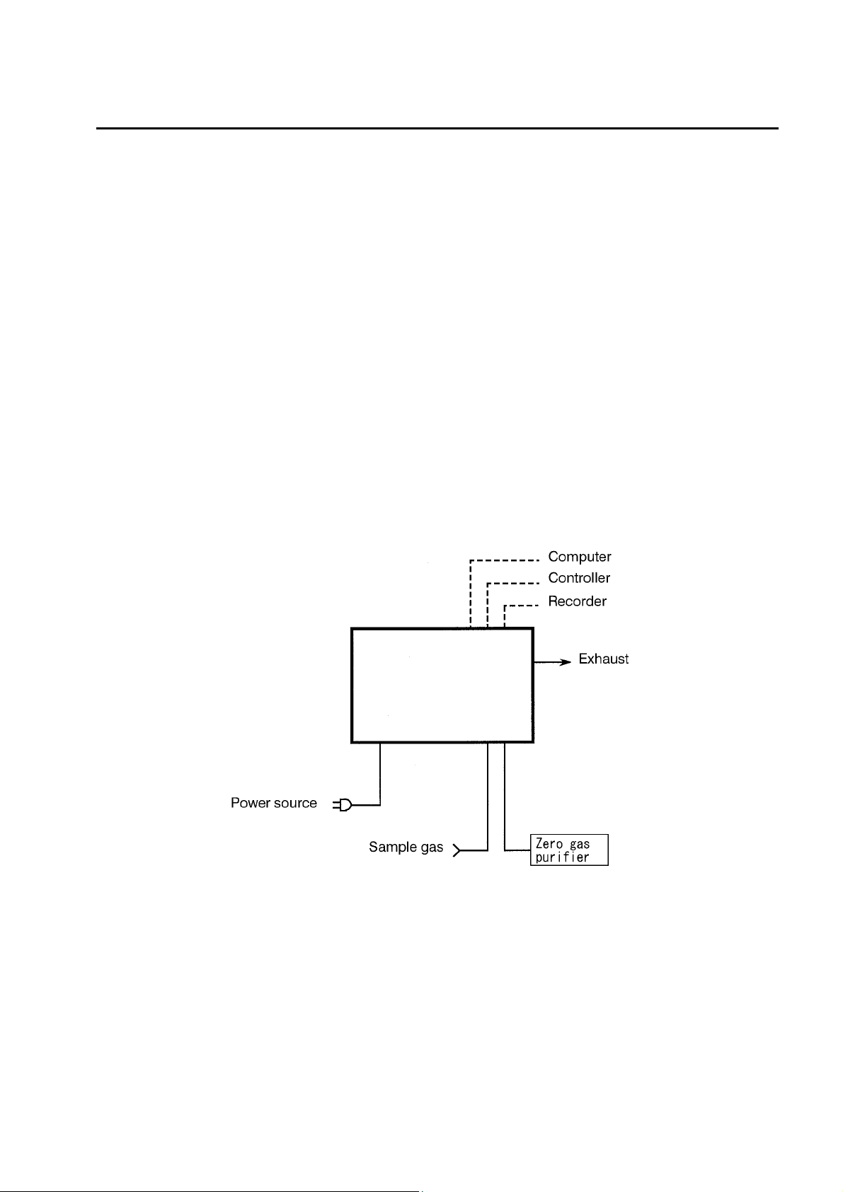
1.2 System Configuration
APOA-370 is a standalone system that allows you to operate it by merely connecting a zero
gas purifier.
The system can be upgraded by connecting a computer, monitor, recorder.
1 OVERVIEW
in the atmosphere.
3
The system configuration of APOA-370 is shown in the following diagram:
APOA-370
Fig. 1 System configuration
1
1 OVERVIEW
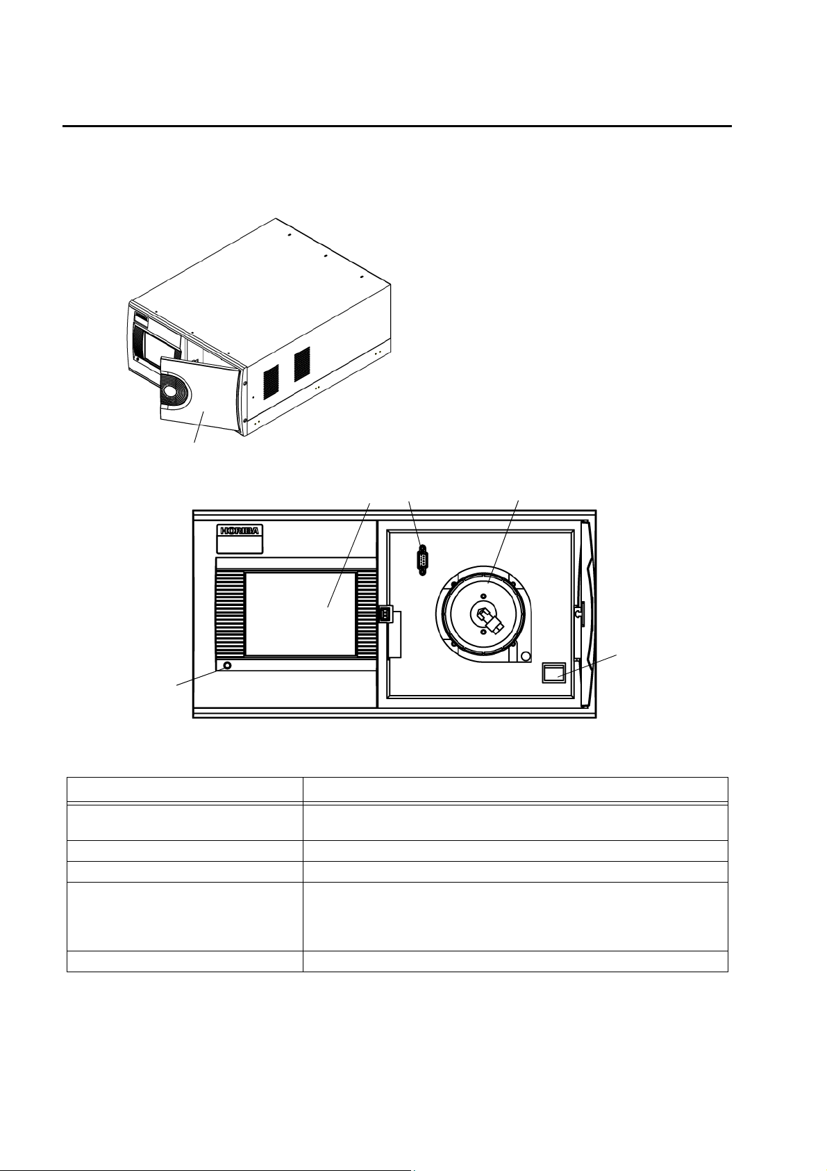
1.3 Part Names
1.3.1 Front panel
Front panel door
When the front panel door is open
1
2
4
5
3
Fig. 2 Front panel
Name Description
1 Power ON LED
2 Touch panel Displays the measured values, alarms, etc. and touch-keys for operation.
3 RS-232C output port Used for maintenance and adjustments.
4 Sample filter
5 Power switch Used to turn ON/OFF the main power supply.
When APOA-370 is ON, this LED is illuminated as follows:
Green: During normal operation Red: In alarm conditions
A filter for the sample line.
Replace this filter about every 2 weeks. (See “ 7.2 Replacing the Filter
Element ” (page 78).
The actual replacement frequency depends on the sample gas conditions.)
2
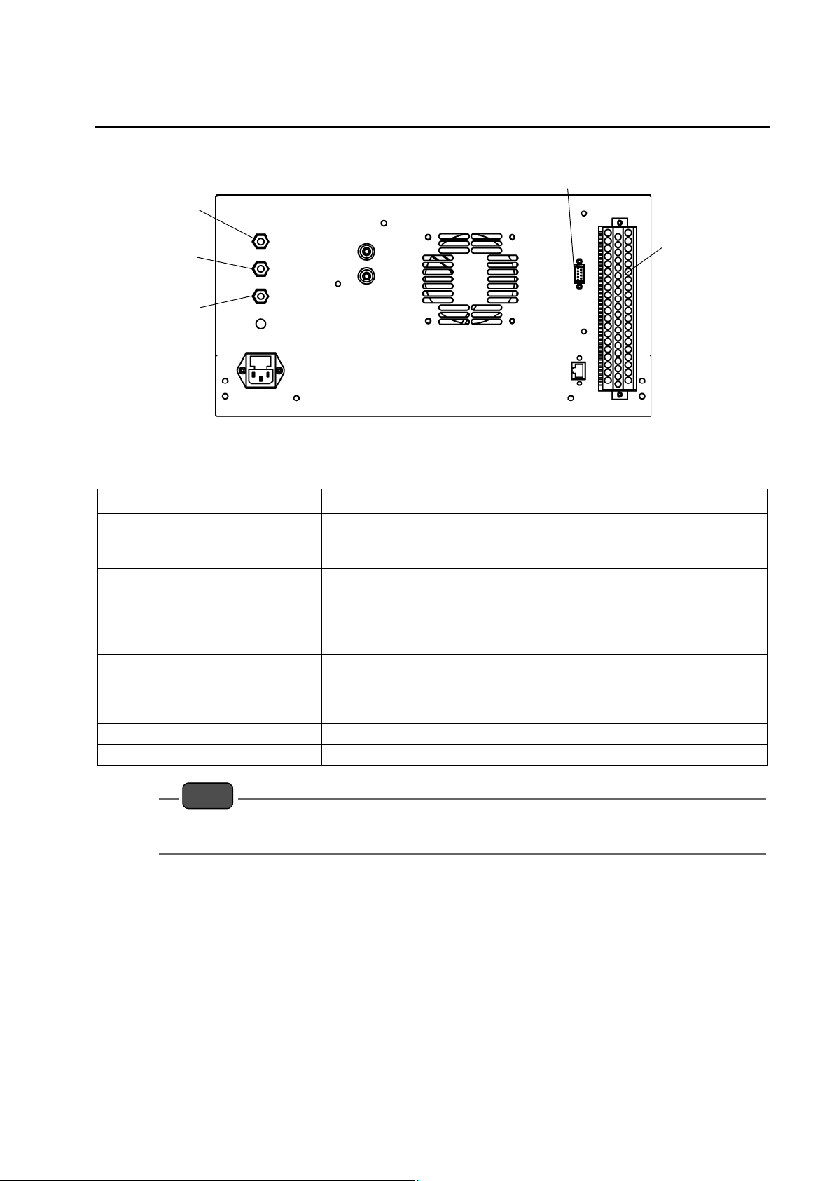
1.3.2 Rear panel
1
1 OVERVIEW
4
2
3
5
Fig. 3 Rear panel
Name Description
The calibration gas inlet with a connector for a Teflon tube of 6 mm O.D./ 4 mm
1 Calibration gas inlet
2 Sample inlet
3 Exhaust outlet
4 RS-232C (optional)
5 Signal connection terminal block For the signals, see “ 9 EXTERNAL INPUT/OUTPUT ” (page 89) .
I.D.
Make sure that the calibration gas pressure stays stable within ±500 Pa.
The sample gas inlet with a connector for a Teflon tube of 6 mm O.D./ 4 mm
I.D.
Make sure that the sample gas pressure stays stable within ±980 Pa.
In order to prevent condensation from occurring, exercise caution to ensure
that the sample piping is not exposed to cool air.
The measured gas outlet with a connector for a Teflon tube of 6 mm O.D./ 4
mm I.D.
Release the measured gas to a safe location where the back pressure stays
stable within a range of ±490 Pa.
Note
The measured gas is released from the exhaust outlet at a rate of 0.7 L/min.
The O
gas used for calibration is toxic. Be sure to connect an exhaust tube.
3
3
2 BASIC OPERATIONS
2 BASIC OPERATIONS
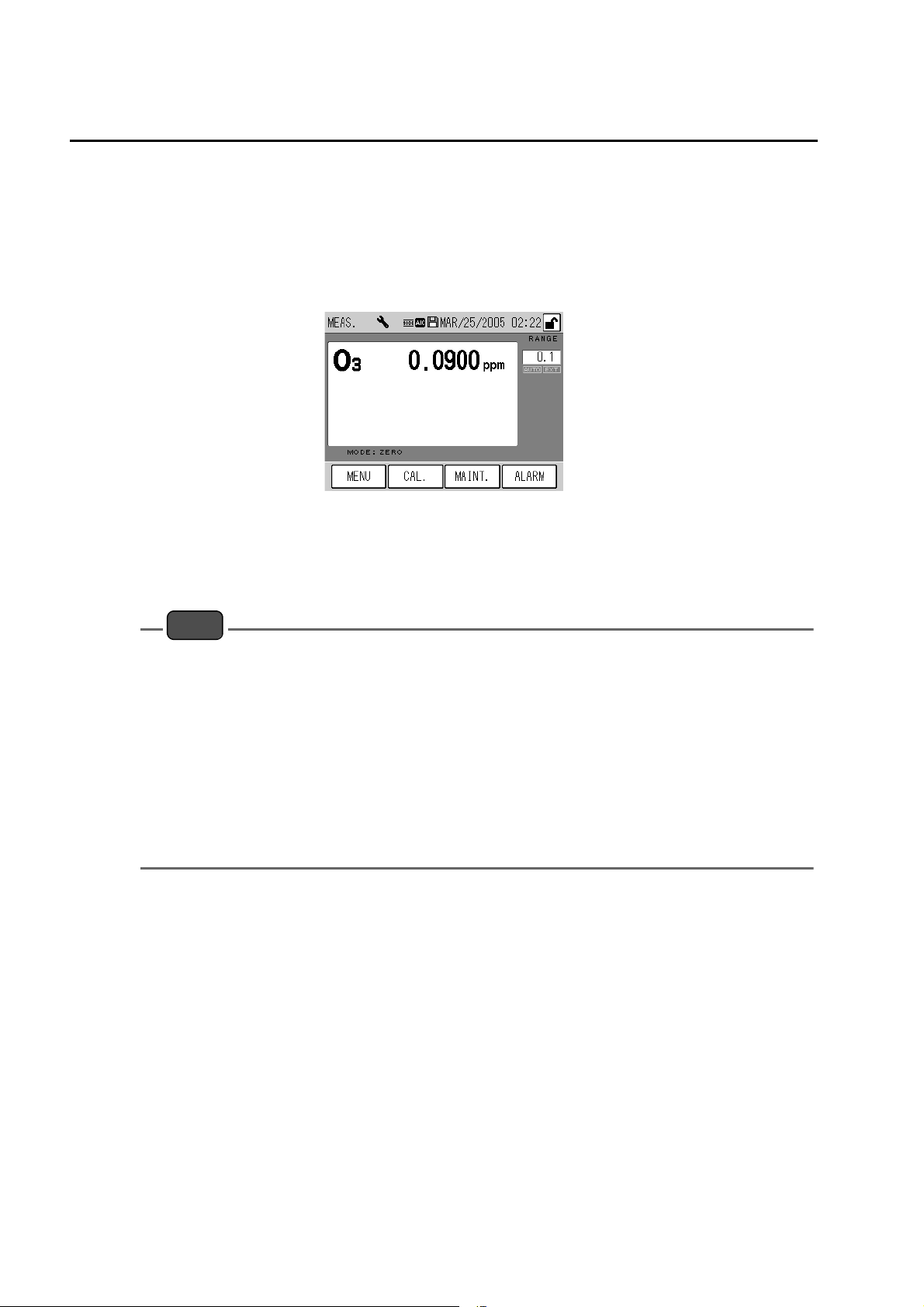
2.1 Start-up (Measurement Start)
1. Power ON
Press the power switch located on the front panel to turn ON the main power supply.
The MEAS. screen is automatically displayed and the measurement starts.
Fig. 4 Initial screen
2. Warm-up
Wait for Warm up time (about 3 hours).
Note
z
The [ALARM] key may be illuminated* during warm-up, but this does not affect the warm-up
process.
If the [ALARM] key is still illuminated 3 hours later, see “ 8.2 Alarm List ” (page 82) to take action.
Since the end of warm-up is not displayed, it is recommended to warm up at night or in any other
time zone when the operation is not affected.
* [ALARM] key Illumination:
The DO (deozonizer temperature) alarm is outputted for about 1 hour after the power is turned
ON.
z
In order to obtain stable, accurate data, perform calibration at the measurement start and regular
intervals (see “ 4 CALIBRATION ” (page 11)).
z
If the data logging capability (optional) for the CF is enabled, data logging is automatically
executed when the APOA-370 is started again due to the power failure, etc.
4

2.2 Shutdown
Note
z
The average and integration values are saved in the flash memory every 10 minutes.
Before turning OFF the power, be sure to save the data in the memory (see “ 6.6.4 Data saving ”
(page 65)).
z
If power outage or a similar accident occurs, data may not be recorded for 10 minutes at a
maximum.
z
If the data logging capability (optional) for the CF is enabled, access to the CF will occur nonperiodically. Be sure to disable the data logging capability before turning OFF the power, so that
the power is not turned OFF during access to the CF. (Turning OFF the power during access to
the CF may damage the data in CF.) (See the Instruction Manual for APXX-370 Series Compact
Flash Memory.)
1. Save the data in the memory (see “ 6.6.4 Data saving ” (page 65)).
2. Ensure that the data logging capability is disabled during data logging (optional).
(See the Instruction Manual for APXX-370 Series Compact Flash Memory.)
3. Turn OFF the power of APOA-370.
Before a long-term shutdown, it is recommended to replace the filter element (see “ 7.2
Replacing the Filter Element ” (page 78)).
2 BASIC OPERATIONS
5
2 BASIC OPERATIONS
2.3 Basic Operation Flow
To perform operations, ensure that the installation, wiring, and piping connections have been
completed.
(Connect the external input/output as necessary.)
Q For the first use
Power ON Turn ON the power. 2.1 Start-up (Measurement Start) (page 4)
↓
Unlock the keys
Set the current time. 6.5.1 Time adjustment (page56)
Setting
↓
Output setting
↓
Password change
↓
Calibration Perform calibration automatically or manually.
↓
Measurement Perform the continuous measurement.
Set the start time, interval for calibration mode or
operation using the internal clock.
Set the calibration sequence (zero span time). 4.3.3 Setting the AIC sequence (page22)
Set the analog output range (Fixed, Auto, or
External).
The default setting is “Auto.”
Select a desired mode in accordance with your
use.
The default value is 1234.
Change this value as necessary.
*1
6.8 Key Lock (page75)
4.3.1 AIC setting (page16)
6.4 Range Menu (page52)
6.6.3 Password setting (page63)
4.3 Automatic Calibration (AIC) (page16)
4.4 Manual Calibration (page26)
*1:The default password is 1234.
6
3 MEAS. SCREEN (BASIC SCREEN)
Note
APOA-370 uses a touch screen. Directly press keys displayed on that screen with your finger.
When pressing these keys, do not use a ballpoint pen or any other tool with a hard or sharp end. This
might cause a malfunction.
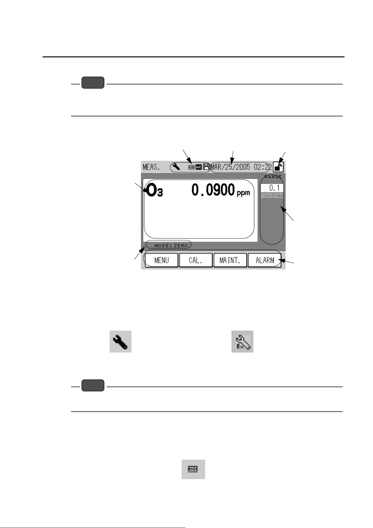
This chapter describes the MEAS. screen that is displayed immediately after the power is
turned ON.
3 MEAS. SCREEN (BASIC SCREEN)
5: Measurement result area
6: Active measurement line display
1: Icon display area
The icons showing the state of the instrument are displayed in this area.
Maintenance mode: This icon blinks when the maintenance switch is turned ON.
1: Icon display area
2: Current time
3: [KEY LOCK] icon (button)
4: Range display
7: Function keys
Fig. 5 MEAS. screen
For the maintenance switch, see “ 7.1 Before Maintenance ” (page 77).
The maintenance switch is ON manually The maintenance switch is ON under external control
Fig. 6 Maintenance mode icon
Note
In the case of the standard specifications, the MNT (Maintenance) signal is outputted when the
maintenance switch is ON.
Mode: This icon is illuminated when gas is being sucked through any line other than
the MEAS. line.
When the gas line is switched to the MEAS. line, this icon remains illuminated
during the MEASURE time specified in the AIC sequence.
Fig. 7 Mode icon
7
3 MEAS. SCREEN (BASIC SCREEN)
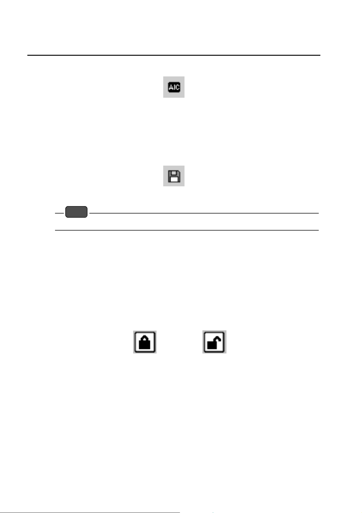
AIC mode: This icon blinks when the AIC sequence is in progress.
Saving: This icon is illuminated when data is being written to the flash memory or when
the data logging capability (optional) is in use.
Data is saved when any setting is modified or every 10 minutes during data
acquisition.
Fig. 8 AIC mode icon
Fig. 9 Saving icon
Note
When the Saving icon is displayed, do not turn OFF the power. If you do that, the data will not saved.
2: Current time
The current time is displayed.
For setting the current time, see “ 6.5.1 Time adjustment ” (page 56).
3: [KEY LOCK] icon (button)
The key locked/unlocked mode is displayed.
When this icon is displayed in a box, it works as the operation button of key lock/unlock.
In this state, pressing this button displays the KEY LOCK screen (Fig. 96 on page 75) allowing
you to lock/unlock the keys.
Keys are locked Keys are unlocked
Fig. 10 [KEY LOCK] icon (button)
When the keys are locked, you cannot operate with the screen; you can only view the screen.
This prevents any wrong operation from causing a modification in the settings.
8
3 MEAS. SCREEN (BASIC SCREEN)
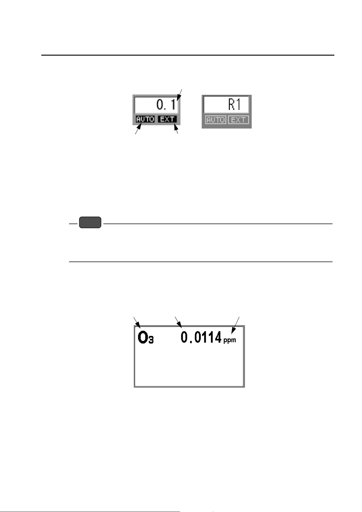
4: Range display
The current range and range mode are displayed.
Momentary value range
AUTO EXT
Fig. 11 Range display
Momentary value range: The current momentary value range is displayed. If the
displayed unit is different from the factory setting, the range is
changed to “RX.” X: The concentration ranges are named as 1,
2, 3, and so forth in the ascending order.
AUTO: Displayed when the automatic range function is used.
EXT: Displayed when the external input for range switching is used.
Note
z
For range setting, see “ 6.4 Range Menu ” (page 52).
z
The external input of range switching can be controlled via contact input (optional) or the RS232C port (optional).
z
For changing the displayed unit, see “5: Measurement result area.”
5: Measurement result area
Measurement results are displayed.
Component
name
Concentration
value
Concentration
unit
Fig. 12 Measurement result area
Component name: The name of the component under measurement is displayed.
Concentration value: The concentration value is displayed.
Concentration unit: The unit of the concentration value is displayed. The unit can be
changed by touching the displayed unit when the keys are unlocked.
You can switch between ppm and mg/m
3
or between ppb and µg/m3.
9

3 MEAS. SCREEN (BASIC SCREEN)
6: Active measurement line display
The currently selected measurement line is displayed.
EXT: Displayed when the external input for line switching is used.
Active measurement line: The currently selected measurement line is displayed.
Note
z
For the external input of line switching, see “ 4.1.2 MODE screen ” (page 12).
z
The external input of line switching can be controlled via contact input (optional) or the RS-232C
port (optional).
Active measurement lineEXT
Fig. 13 Active measurement line display
z
ZERO: The zero gas line is now being selected.
z
SPAN: The span gas line is now being selected.
z
MEAS.: The measured line is now being selected.
7: Function keys
The keys allow you to perform the following operations.
[MENU]: The MENU screen (Fig. 47 on page 39) is displayed.
[CAL.]: The CAL. screen (Fig. 14 on page 11) is displayed.
[MAINT.]: The MAINTENANCE screen for operating the maintenance switch (Fig.
98 on page 77) is displayed.
[ALARM]: Displayed when an error occurs in the instrument.
Pressing the displayed [ALARM] key will allow you to view the current
alarms.
For the details of alarms, see “ 8 TROUBLESHOOTING ” (page 80).
10
4 CALIBRATION
In order to acquire stable, accurate data, perform calibration when starting measurement and
at regular intervals.
For the APOA-370, normally perform the zero calibration only.
The span calibration should be periodically performed using an ozonizer or the like (generally
by using an ultraviolet lamp). At this time, assay the concentration of ozone in accordance
with the ozone concentration assay specified in JIS B7957.
There are two types of calibration, the auto calibration (AIC) and the manual calibration.
Auto calibration (AIC)
The AIC sequence is executed at the specified time intervals or with the externally inputted
command to perform the zero calibration and span calibration automatically.
Manual calibration
This calibration is performed manually at an arbitrary timing.
There are two methods available for the manual calibration; one uses the calibration gas line,
and the other supplies the calibration gas to the measured gas line.
4 CALIBRATION
4.1 Calibration-related Screens
This section describes the screens used for the automatic calibration and manual calibration.
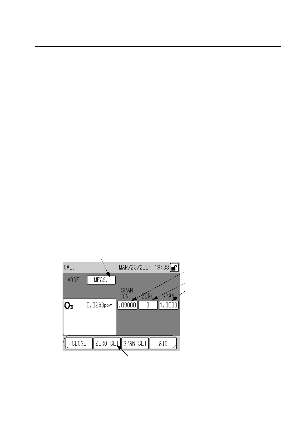
4.1.1 CAL. screen
This is the basic screen for calibration.
To display the CAL. screen, press the [CAL.] key on the MEAS. screen (Fig. 5 on page 7).
1: MODE
2: Span gas concentration value
3: Zero calibration coefficient
4: Span calibration coefficient
5: Function keys
Fig. 14 CAL. screen
1: MODE
The selected measurement line is displayed.
Press the displayed MODE setting, and the MODE screen will be displayed (see “ 4.1.2
MODE screen ” (page 12)).
11
4 CALIBRATION
2: Span gas concentration value
The entered span gas concentration value is displayed.
Different values can be entered for the measured gas and span gas lines.
Press the displayed span gas concentration value, the SPAN CONC. screen will be displayed
(see “ 4.1.3 Screens for value setting ” (page 13)).
No span gas concentration value can be entered when the ZERO line is set for MODE.
3: Zero calibration coefficient
The entered zero calibration coefficient is displayed.
Press the displayed zero calibration coefficient, the ZERO ADJUST screen will be displayed
(see “ 4.1.3 Screens for value setting ” (page 13)).
4: Span calibration coefficient
The entered span calibration coefficient is displayed.
Press the displayed span calibration coefficient, the SPAN ADJUST screen will be displayed
(see “ 4.1.3 Screens for value setting ” (page 13)).
Note
5: Function keys
The keys allow you to perform the following operations.
[CLOSE]: Returns to the MEAS. screen (Fig. 5 on page 7).
[ZERO SET]: Displays the zero calibration message (Fig. 36 on page 27).
[SPAN SET]: Displays the span calibration message (Fig. 38 on page 28).
[AIC]: Displays the AIC start message (Fig. 33 on page 25).
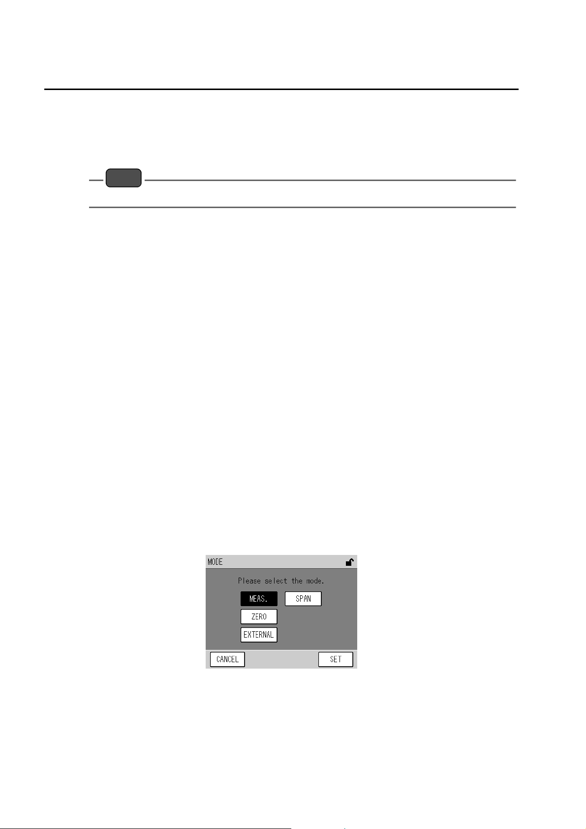
4.1.2 MODE screen
The measurement line can be switched on this screen.
Pressing this key during the execution of AIC (the AIC mode icon blinks) displays the AIC abort message (Fig. 34 on page 25).
12
Fig. 15 MODE screen
Press the button for the item to be set.
MEAS.: To use the MEAS. line, select this button.
SPAN: To use the SPAN line, select this button.
ZERO: To use the ZERO line, select this button.
EXTERNAL: To use the external contact (optional) for line switching, select this button.
The keys allow you to perform the following operations.
[CANCEL]: Returns to the CAL. screen without changing the settings.
[SET]: Returns to the CAL. screen with the settings changed.
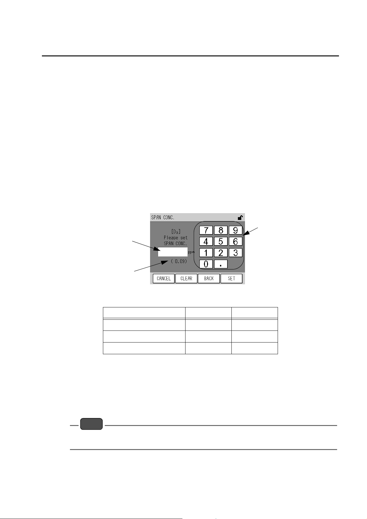
4.1.3 Screens for value setting
Pressing each display of span gas concentration value, zero calibration coefficient, or span
calibration coefficient will display a screen including the numeric keypad that allows you to
enter the respective values.
4 CALIBRATION
Numeric keypad
Edit area
Current set value
Fig. 16 A screen for value setting (SPAN CONC.)
Item Settable range Default setting
Span gas concentration value .00001 to 99999. ---
Zero calibration coefficient −3500 to 3500 0
Span calibration coefficient .50000 to 2.0000 1.0000
Enter a value via the numeric keypad.
The keys allow you to perform the following operations.
[CANCEL]: Returns to the CAL. screen without changing the settings.
[CLEAR]: Deletes the value entered in the edit area
[BACK]: Deletes the just entered figure (1-digit).
[SET]: Returns to the CAL. screen with the settings changed.
Note
If you enter any value that does not meet the settable range, it will be automatically corrected to the
nearest value in the settable range.
13
4 CALIBRATION
4.2 Preparation for Calibration
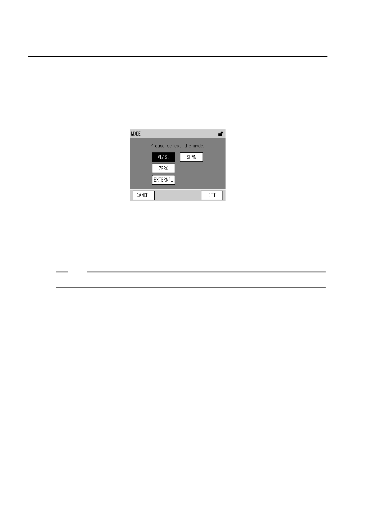
4.2.1 Entering the span gas concentration value
Enter the span gas concentration value to be used for the calibration.
1. Press the displayed MODE setting on the CAL. screen. The MODE screen will be
displayed.
Fig. 17 MODE screen
2. Select the measurement line corresponding to the line to be used for the
calibration.
z
For manual calibration using the calibration gas line: [SPAN]
z
For manual calibration using the measured gas line: [MEAS.]
z
For auto calibration (AIC): [SPAN]
Tip
Two different calibration gas concentrations can be set for the [SPAN] and [MEAS.] lines.
3. Press the [SET] key to return to the CAL. screen.
14
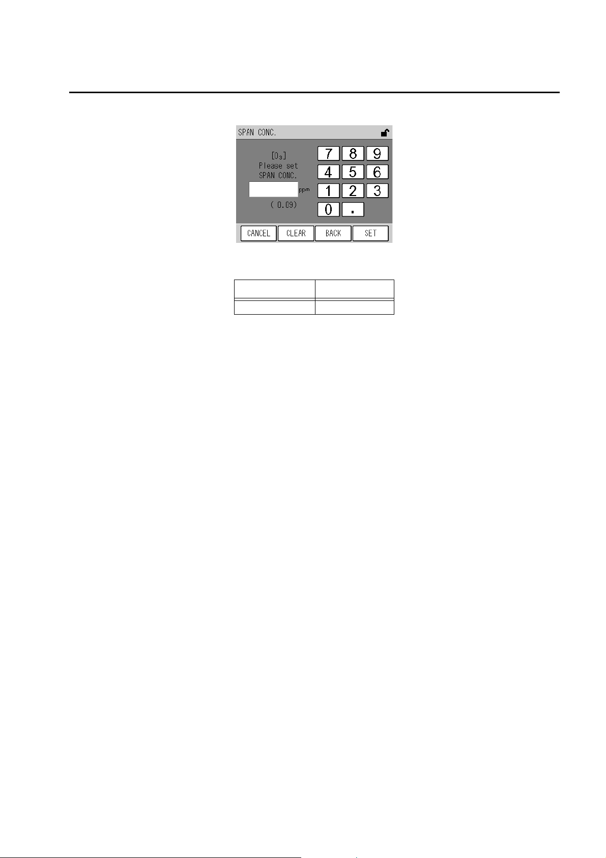
4 CALIBRATION
4. Press the displayed Span Conc. value. The SPAN CONC. screen will be displayed.
Fig. 18 SPAN CONC. screen
item Settable range
Span Conc. value .00001 to 99999.
Enter a value via the numeric keypad.
The keys allow you to perform the following operations.
[CANCEL]: Returns to the CAL. screen without changing the settings.
[CLEAR]: Deletes the value entered in the edit area
[BACK]: Deletes the just entered figure (1-digit).
[SET]: Returns to the CAL. screen with the settings changed.
5. Enter a span gas concentration via the numeric keypad.
6. Press the [SET] key to return to the CAL. screen.
15
4 CALIBRATION
4.3 Automatic Calibration (AIC)
Automatic calibration (AIC) is started and performed with the internal clock, according to the
AIC sequence and conditions set in advance. The AIC sequence can also be started arbitrarily
by pressing the [AIC] key on the CAL screen.
4.3.1 AIC setting
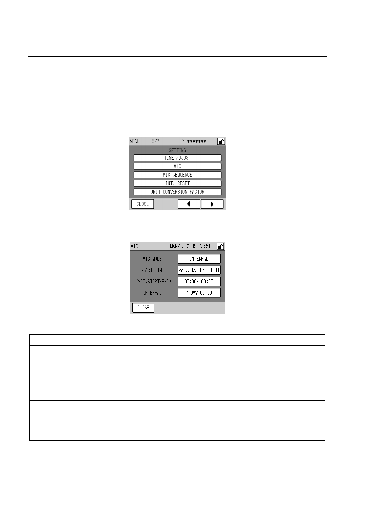
1. Press the [MENU] key on the MEAS. screen.
2. Press either the [W] or [X] key to display the MENU/SETTING screen.
3. Press the [AIC] button. The AIC screen will be displayed.
Item Description
AIC MODE
START TIME
LIMIT (START-END)
INTERVAL
Fig. 19 MENU/SETTING screen
Fig. 20 AIC screen
Used to specify the method of AIC start.
Pressing the displayed AIC MODE setting will display the AIC MODE screen (Fig. 21 on page
17).
Used to set the time for starting the next AIC sequence.
When the internal clock reaches or exceeds the specified time, the AIC sequence will start.
Pressing the displayed START TIME setting will display the START TIME screen (Fig. 22 on
page 18).
Used to set the range of time available for starting the AIC sequence.
Pressing the displayed LIMIT (START-END) setting will display the LIMIT (START-END) screen
(Fig. 23 on page 19).
Used to set the time interval, which applies if the AIC sequence is started periodically.
Pressing the displayed INTERVAL setting will display the INTERVAL screen (Fig. 24 on page 20).
16
4 CALIBRATION
Note
Only when AIC MODE is set to INTERNAL, the items of START TIME, LIMIT (START-END), and
INTERVAL are displayed. These items are not displayed when AIC MODE is set to NONE or
EXTERNAL.
4. Press the displayed item to be set. The corresponding setting screen will be
displayed.
For the detailed explanation of each screen, see page 17 to page 21.
5. On the setting screen, change the settings and then press the [SET] key.
The changed settings will be saved, and the AIC screen will be displayed again.
Tip
To cancel the changes, press the [CANCEL] key. The changes will be undone, and the AIC screen will
be displayed again.
6. Press the [CLOSE] key on the AIC screen to return to the MENU screen.
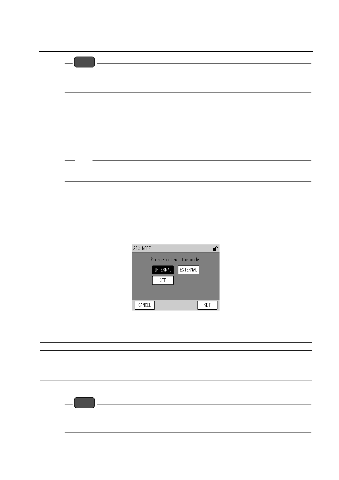
Q AIC MODE
Specify the method of starting the AIC.
Pressing the displayed AIC MODE setting will display the AIC MODE screen.
Fig. 21 AIC MODE screen
Item Description
INTERNAL Selects the mode of using the internal clock to execute AIC at the specified start time and intervals with.
Selects the mode of using the external start signal (external contact input) to start AIC.
EXTERNAL
OFF Selects the mode without AIC automatic start.
For the telemeter connection specifications, if the telemeter input contact is open (telemeter malfunction),
AIC will be started using the internal clock.
Press the button of the item to be set.
Note
z
Manual AIC start and the start via the RS-232C port are valid regardless of this setting.
z
If an AIC start signal is inputted externally while an AIC sequence is in progress, this signal will
be disregarded and the ongoing AIC sequence will be continued.
17
4 CALIBRATION
For the telemeter connection specifications, to execute AIC using the internally set START TIME and
INTERVAL automatically even if the start signal is not inputted because of telemeter malfunction, set
AIC MODE to EXTERNAL.
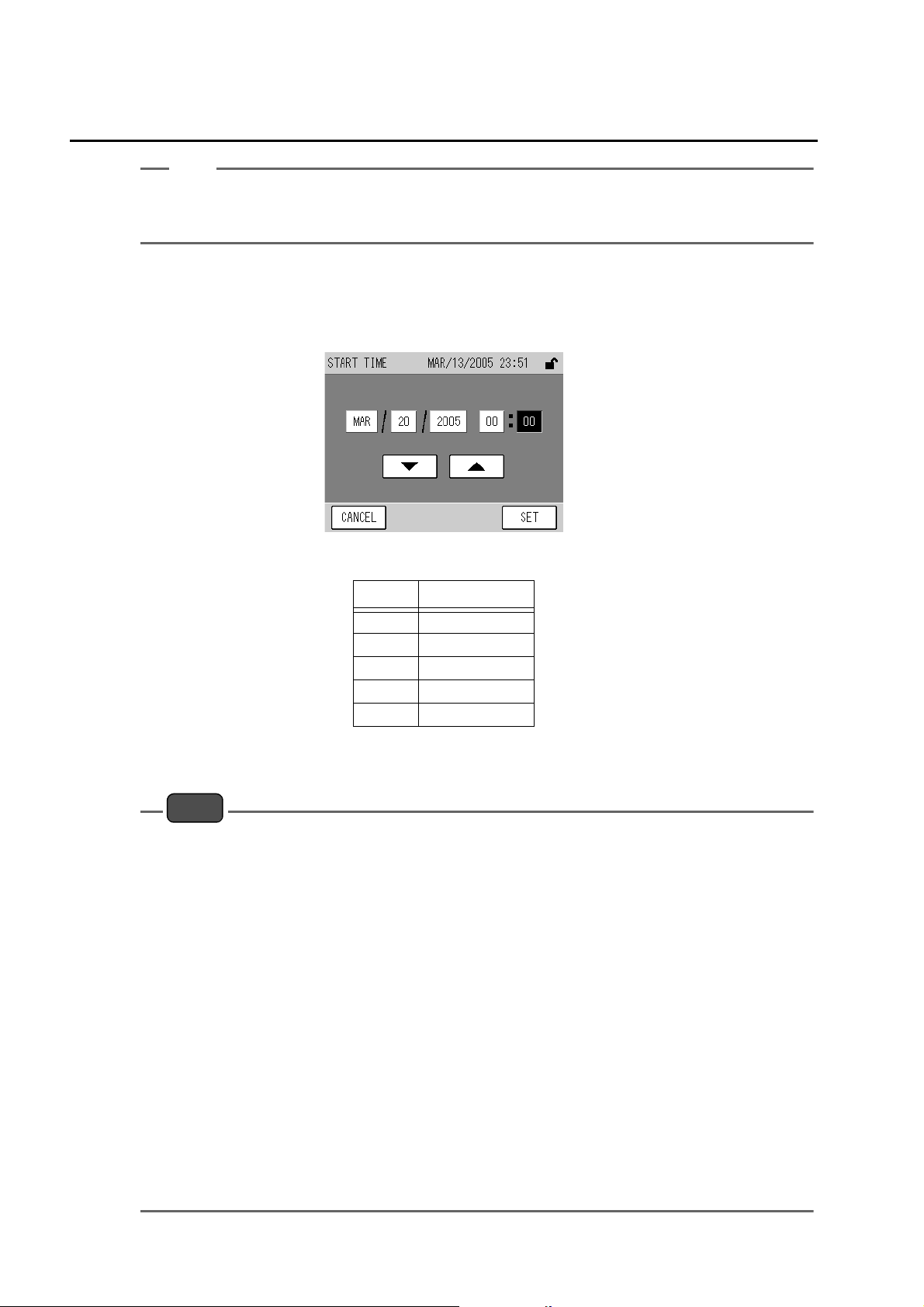
Q START TIME
Set the time for starting the next AIC sequence.
Pressing the displayed START TIME setting will display the START TIME screen.
Tip
Fig. 22 START TIME screen
Item Settable range
Year 2000 to 2099
Month 01 to 12
Day 01 to 31
Hour 00 to 23
Minute 00 to 59
Press the value to be changed. The value will be highlighted, allowing you to change it.
Using the [T] and [S] buttons, change the value.
Note
z
The START TIME setting is based on the internal clock.
z
The practical range of Year setting is 2000 to 2089.
z
The START TIME can not be set to any date that does not practically exist.
If the [SET] key is pressed with such a value entered, the nearest date and time will be set
automatically.
z
The START TIME can not be set to any time outside the current LIMIT (START-END) setting.
If the [SET] key is pressed with such a value entered, the setting is changed automatically so as
to be within the range.
z
Once the AIC sequence starts, the START TIME setting will be changed to the expected START
TIME of the next AIC (the current START TIME + INTERVAL). If the calculated time does not meet
the settable ranges of the LIMIT (START-END), it will be corrected automatically (see “ 4.3.2
Precautions in setting the AIC sequence ” (page 21)).
z
If the START TIME is set to any time earlier than the current time, the setting will be changed to
the minimum later than the current time, which is obtained by adding an integral multiple of the
INTERVAL setting to the current START TIME. If the calculated time does not meet the settable
ranges of the LIMIT (START-END), it will be corrected automatically.
z
If the START TIME becomes earlier than the current time by adjusting the internal clock (see “
6.5.1 Time adjustment ” (page 56)), the setting will be changed to the minimum later than the
current time, which is obtained by adding an integral multiple of the INTERVAL setting to the
current START TIME. If the calculated time does not meet the settable ranges of the LIMIT
(START-END), it will be corrected automatically.
18
4 CALIBRATION
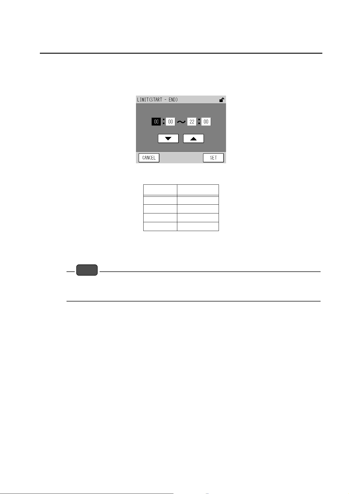
Q LIMIT (START-END)
Set the range of time available for starting the AIC sequence.
Pressing the displayed LIMIT (START-END) setting will display the LIMIT (START-END)
screen.
Fig. 23 LIMIT (START-END) screen
Item Settable range
Start: Hour 00 to 23
Start: Minute 00 to 59
End: Hour 00 to 23
End: Minute 00 to 59
Press the value to be changed. The value will be highlighted, allowing you to change it.
Using the [T] and [S] buttons, change the value.
Note
z
When you do not use the LIMIT (START-END) function, select the default value (00:00 to 00:00).
z
If the START and END values of the range are the same, the LIMIT (START-END) function is
invalid.
19
4 CALIBRATION
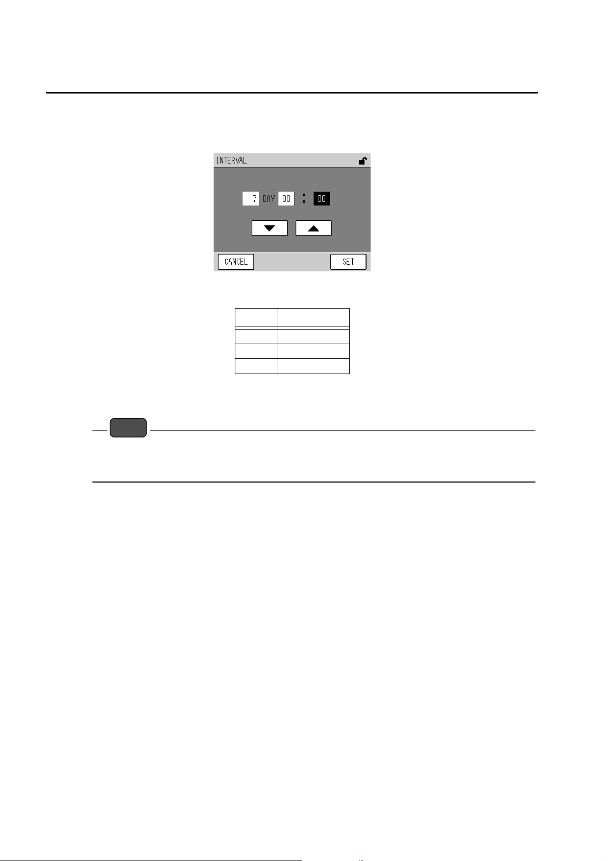
Q INTERVAL
Set the time interval, which applies if the AIC sequence is started periodically.
Pressing the displayed INTERVAL setting will display the INTERVAL screen.
Fig. 24 INTERVAL screen
Item Settable range
Day 0 to 999
Hour 00 to 23
Minute 00 to 59
Press the value to be changed. The value will be highlighted, allowing you to change it.
Using the [T] and [S] buttons, change the value.
Note
INTERVAL should be set to the AIC sequence time plus 10 minutes or longer.
If the [SET] key is pressed with a shorter interval entered, the period equivalent to the AIC sequence
time plus 10 minutes will be set automatically.
20
 Loading...