

Page 1

Operating Manual
HOPPECKE sun | powerpack premium
Page 2

BA_sun_power_pack_LiOn_en_V1.05.docx V1.05 (20/07/2017) 6140203036
Foreword
Dear Customer,
Thank you very much for having decided in favour of a product bearing our brand name.
Before working on the battery system or its components, please read this documentation
carefully. It contains important information on secure and professional unpacking, storing,
installing, operating and maintaining the sun|powerpack premium battery system.
Amendments to this documentation are subject to change without prior notice. Our products
undergo continuous advanced development. As a result, there may be deviations between
the illustrations given in this documentation and the purchased product. This installation
manual is not covered by any change service.
Keep this documentation in such a manner that it is available immediately to all those who
need to carry out work in connection with the battery system or its components.
Service Hotline Germany:
0800 246 77 32
International service hotline:
+49 (0) 180 5 22 9999
Internet: www.HOPPECKE.com
Email: [email protected]
Copyright HOPPECKE Batterien GmbH & Co. KG
All rights reserved including those of patent and utility model applications.
Disclosure of as well as copying this documentation and using or revealing its contents are
not permissible unless this has been expressly approved in writing by HOPPECKE Batterien
GmbH. Infringements will lead to liability for damages.
Page 3

BA_sun_power_pack_LiOn_en_V1.05.docx V1.05 (20/07/2017) 6140203036 3
Table of contents
1. TARGET GROUP 5
2. MEANS OF REPRESENTATION 6
3. SAFETY INSTRUCTIONS 7
3.1. General Safety Instructions 7
3.2. Intended Use 8
3.3. Directives, Legislation and Standards 8
3.4. Obligations of the Operator 9
3.5. Occupational safety 9
3.5.1. Personnel and Qualification 9
3.5.2. Personal Protective Equipment 10
3.6. Special information on Li-Ion batteries 10
3.6.1. First-aid measures if cell contents leak out 11
3.6.2. Fire-fighting procedures 11
3.6.3. Disposal instructions 12
3.7. Transport 12
3.7.1. Intact, undamaged batteries and batteries at the end of their service life 13
3.7.2. Defective batteries 14
3.7.3. Check the delivery 14
4. SUN|POWERPACK PREMIUM BATTERY SYSTEM 16
4.1. Hints for sizing of the system 18
5. STORAGE 19
5.1. Intact, undamaged batteries and batteries at the end of their service life 19
5.2. Defective batteries 19
6. PREPARING FOR INSTALLATION 20
6.1. Installation site 20
6.2. Tools and Equipment 21
7. INSTALLATION 22
7.1. Assembling and installing the housing 22
7.1.1. Grounding the housing 24
7.2. Installing the battery stacks 25
7.3. Connecting the battery stacks electrically 30
7.4. Connecting the battery inverter 34
7.5. Commissioning 36
7.6. Final work 37
Page 4

Target Group
BA_sun_power_pack_LiOn_en_V1.05.docx V1.05 (20/07/2017) 6140203036 4
8. REGISTERING THE BATTERY SYSTEM 39
9. OPERATING THE BATTERY SYSTEM 40
9.1. Safety Functions 42
9.2. Display Unit 42
9.3. Operating states 43
10. MAINTENANCE AND CARE 45
10.1. Cleaning 45
10.2. Repair Work 45
10.3. BMS software update 45
11. END OF SERVICE LIFE 46
12. WARNING AND ERORR MESSAGES 47
13. SYSTEM EXPANSION 49
14. DISASSEMBLY 49
15. TECHNICAL SPECIFICATIONS 50
15.1. System 50
15.2. Battery cell 50
15.3. Norms and Standards 50
16. CE DECLARATION OF CONFORMITY 51
17. ABBREVIATIONS 52
18. FURTHER INFORMATION 53
19. APPENDIX 54
19.1. Certification of the function of the smoke detector 54
19.2. Certification of installation and commissioning 54
Page 5

Target Group
BA_sun_power_pack_LiOn_en_V1.05.docx V1.05 (20/07/2017) 6140203036 5
1. Target Group
This Operating Manual is meant for dealers, electricians and end users. It describes the
transport, storage, installation, operation, maintenance and disassembly of the
sun|powerpack premium battery system. The work of installation, maintenance and
disassembly should be done only by electricians.
Note:
Proper installation and commissioning must be certified by the respective electrician with his
signature in this operating manual (see chapter 19). The signed operating manual must remain
with the end user of the battery system.
Page 6
Means of Representation
BA_sun_power_pack_LiOn_en_V1.05.docx V1.05 (20/07/2017) 6140203036 6
2. Means of Representation
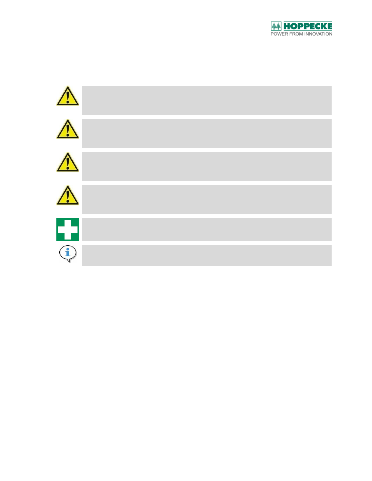
The following icons and signal words have been used in this operating and maintenance
manual:
DANGER!
Denotes an immediate hazard with a high level of risk that could lead to death or severe physical
injury if it is not prevented.
WARNING!
Denotes a potential hazard with a medium level of risk that could lead to death or severe physical
injury if it is not prevented.
CAUTION!
Denotes a hazard with a low level of risk that could lead to minor or medium degree of physical
injury if it is not prevented.
ATTENTION!
Denotes a hazard in which the product, other objects or the environment may get damaged if it is
not prevented.
Denotes first-aid measures.
Note:
Denotes instructions that are important for optimal utilisation of the product.
Page 7

Safety Instructions
BA_sun_power_pack_LiOn_en_V1.05.docx V1.05 (20/07/2017) 6140203036 7
3. Safety Instructions
Observe and follow the safety instructions given below when handling the sun|powerpack
premium battery system as well as its components.
3.1. General Safety Instructions
DANGER!
Metallic parts of the batteries are always live. Do not short-circuit the batteries! Very high values
of current may flow and cause burn injuries in case of a short-circuit. Touching electrically
conducting parts may cause cardiac arrhythmia and shock.
Please be very careful when doing any work on the battery system in order to prevent severe
injuries caused by electrical shocks or burns.
Never place tools or other metallic objects on a battery.
Be sure to remove watches and jewellery before doing any work on the batteries.
Do not touch any exposed battery parts, jumpers, terminals or poles!
Just as with other batteries, lithium-ion batteries may represent a source of hazard even in an
apparently discharged condition by high short-circuit currents.
DANGER!
The battery stacks and the included battery cells should not be damaged mechanically
(puncturing, deforming or disassembling). Keep away from open flames or sources of intense
heat. There is a risk of heat developing and leakage of liquid electrolyte and gases.
DANGER!
At temperatures above 80 °C there is danger of the Li-Ion batteries bursting and the discharge of
liquid electrolyte and gases. There is danger of the escaping materials igniting. Reactions of the
electrolytes and the electrodes with water and humidity are possible.
Use only those battery chargers that have been approved by HOPPECKE for use with
sun|powerpack premium.
ATTENTION!
The use of an automatic smoke alarm system is necessary at the place of installation.
ATTENTION!
Children must be kept away from the battery system.
Note:
Observe and follow this operating manual and keep it such that it is easily visible at the
installation site of the battery system.
Page 8
Safety Instructions
BA_sun_power_pack_LiOn_en_V1.05.docx V1.05 (20/07/2017) 6140203036 8
3.2. Intended Use
The sun|powerpack premium battery system serves to store electrical energy. It is set up
and wired at the installation site. The battery system should be operated only with approved
battery inverters / battery chargers. A list of approved battery inverters / battery chargers
can be downloaded from www.hoppecke.com (see also chapter 7.4).
DANGER!
Unintended use of the batteries may lead to personal injuries or damage to property.
In case of unintended use, HOPPECKE Batterien GmbH & Co. KG shall not assume any liability
for personal injuries or damage to property that result directly or indirectly from handling the
batteries.
The operator shall be solely responsible for the risks arising from unintended use.
ATTENTION!
The sun|powerpack premium should not be used as an emergency power supply system, if the
failure of the loads connected may lead to personal injuries (e.g. for power supply to medical
devices with life-sustaining functions).
ATTENTION!
Only those inverters that have been approved by HOPPECKE must be used. The overall system
comprising inverter, PV system, battery system and any other components must be designed
diligently. In the process, the system parameters and limit values of the battery as well as all
relevant norms and standards must be complied with.
3.3. Directives, Legislation and Standards
Observe and follow the rules and regulations applicable to the installation and operation of
stationary battery installations.
Please observe the latest edition of each of the following rules and regulations:
Accident prevention regulations, especially DGUV rule 3 (formerly BGV-A3): Electrical
systems and equipment
DIN EN ISO 20345 ("Personal safety gear – Safety boots")
DIN VDE 100/IEC 60364 ("Erection of low-voltage installations")
DIN EN 50110/VDE 0105 ("Operation of electrical installations")
DIN EN 50272/VDE 0510 ("Safety requirements for secondary batteries and battery
installations")
DIN VDE 1000-10 ("Requirements for persons working near electrical equipment")
VDE-AR-E 2510-50 (“Stationary energy storage systems with lithium batteries”)
Please note that different and further rules and regulations may be required outside
Germany . Please observe local rules and regulations accordingly.
Page 9

Safety Instructions
BA_sun_power_pack_LiOn_en_V1.05.docx V1.05 (20/07/2017) 6140203036 9
3.4. Obligations of the Operator
Please keep the documentation in such a manner that it is available immediately to all
persons who need to carry out work in connection with the batteries or their components.
WARNING!
The requirements for safe operation of the battery installation must be complied with for
subsequent modifications at the installation site. Otherwise, any claims for warranty become null
and void.
3.5. Occupational safety
This section contains important information that needs to be observed and followed while
working on the sun|powerpack premium and its components.
Prohibit all work methods that endanger the safety of human beings and impair the
working of the batteries in any manner.
Maintain the work sequence described in the documentation while installing, dismantling
or connecting the battery terminals to the battery inverter / battery charger.
Pay attention to the polarity of the battery stacks.
Ensure that the battery connection cables are fitted tightly. Use only the battery
connecting cables supplied along with the battery.
Battery stack connections should not be made or removed while current is flowing
through the battery connection cables. Before opening the charging circuit, check the
condition of the battery inverter / battery charger by measuring the voltage. Secure the
battery inverter / battery charger against being switched on again.
Observe and follow the operating manuals of the battery inverter / battery charger
manufacturer.
3.5.1. Personnel and Qualification
Work on the battery system, especially its installation, maintenance and disassembly should
be done only by electricians.
Two persons are necessary for the installation and subsequent disassembly. The personnel
must
be well-versed with handling the batteries,
be aware of the precautionary measures that are necessary,
be trained in accordance with DIN VDE 1000-10 and DGUV regulation 3 (formerly BGV
A3) and if applicable local rules and regulations containing requirements for persons
working near electrical equipment.
Please read the documentation carefully before you do any work on the sun|powerpack
premium or its components. It contains important information on secure and professional
unpacking, storing, installing, operating and maintaining the battery system safely and
properly.
Please make sure to contact your local authorised dealer if:
you have any queries on this documentation.
there are local regulations or provisions that are not covered by this documentation or
are contrary to its contents.
Page 10
Safety Instructions
BA_sun_power_pack_LiOn_en_V1.05.docx V1.05 (20/07/2017) 6140203036 10
3.5.2. Personal Protective Equipment
While working on the sun|powerpack premium or its components, always wear the following
protective equipment in order to prevent injuries or at least to mitigate them:
Safety goggles
Safety gloves
3.6. Special information on Li-Ion batteries
Lithium-Ion batteries are safe if used properly. However, incorrect or improper handling may
lead to leakages and thus, the discharge of the battery constituents. There is the risk of
considerable reactions endangering health and the environment.
DANGER!
Defective batteries may reach conditions that are critical to safety. As a consequence of this, the
batteries may burst or catch fire and hazardous decomposition products may be formed. In case
liquid or gaseous substances are leaking, leave the room immediately and alert the fire brigade.
DANGER!
Basically, coming into contact with battery constituents that have leaked out may pose hazard for
health and the environment. This is why adequate physical protection is necessary and adequate
ventilation must be provided when coming into contact with abnormal batteries (discharge of
contents, deformations, discolouration, bulges or similar). Explosive gases may get released.
Lithium ion batteries may react very severely, for example in combination with fire.
WARNING!
In case of damaged or defective battery cells in sun|powerpack premium or any abnormalities in
the battery system, shut down operation of the battery system immediately. To do this, pull out
the connector of the battery connecting cable at the top of the battery system.
The following measures are applicable only if the battery system is damaged causing
damage to the battery cells and the cell contents start leaking:
Do not inhale vapours that get discharged. Leave the room immediately in case of
smoke development or gas release.
Instructions for specialists: Damaged batteries must be surrounded with dry sand,
chalk powder (CaCO3) or Vermiculite. If possible, they should be stored outside the
buildings. They should best be stored in a sealed, shock-proof and fire-proof external
packaging. The storage place should be marked and safeguarded with warning signs; in
case the battery causes smoke development the storage place must also be monitored.
Make sure to maintain a safe distance to combustible materials with Li-Ion batteries in
any case.
CAUTION!
Do not allow leakage to get into sewer system/surface water/ground water.
Page 11
Safety Instructions
BA_sun_power_pack_LiOn_en_V1.05.docx V1.05 (20/07/2017) 6140203036 11
Method for cleaning by specialists: Pick up residues mechanically with liquid-binding
material (e.g. sand, sawdust, universal binding agents and diatomite). Dispose of picked up
material in accordance with regulations. Avoid direct contact with the skin and eyes by
wearing protective clothing.
3.6.1. First-aid measures if cell contents leak out
If vapours are inhaled:
Take the affected persons to open air and have them rest quietly. Consult a physician.
In case of contact with skin:
In case of contact with skin, rinse with plenty of water immediately and thoroughly for at least 15
minutes. If skin irritation persists, consult a physician.
In case of contact with eyes:
In case of contact with eyes, rinse immediately and thoroughly with water for at least 15 minutes
and consult a physician. Protect uninjured eyes.
If swallowed:
Consult a physician immediately.
3.6.2. Fire-fighting procedures
Critical conditions may arise as a result of fire, short-circuits, high temperatures (more than
80 °C), intense mechanical impacts or damage. As a consequence of this, the battery cells
may burst or catch fire and hazardous decomposition products and gases may be formed.
WARNING!
If a cell decomposes as a result of mechanical damage or blows off thermally, temperatures up to
800 °C occur on the surface of the cell, the cell opens up and blows off its contents under
excessive pressure. In this process, a white / grey mist is formed in most cases that contains the
electrolytes and other cell constituents. This may also ignite and thus cause a jet of flame (see
also /1/).
WARNING!
Leaking gases are harmful to health and flammable. Without appropriate protective equipment
you must leave the place of fire immediately.
This white mist formed is toxic and corrosive! It can dissolve on the moist surface of the skin and
lead to chemical burns.
ATTENTION!
Alert the fire brigade immediately in case of fire. Inform the disaster relief force that there is a
Lithium-Ion (Li-Ion) battery system located in the building.
Page 12
Safety Instructions
BA_sun_power_pack_LiOn_en_V1.05.docx V1.05 (20/07/2017) 6140203036 12
3.6.3. Disposal instructions
Disposal should be done in accordance with the European Batteries Directive and the German
Batteries Act (2006/66/EC).
Coordinate the disposal of apparently damaged batteries with the manufacturer HOPPECKE.
Used batteries that bear the recycling symbol are renewable products.
According to the label with the crossed-out garbage can, these batteries must not be set out with
the household rubbish. Returning and recycling the batteries must be agreed upon with the
manufacturer and ensured.
3.7. Transport
To prepare lithium-ion batteries for transport, they should be packed in the original
packaging such that they are safeguarded against short-circuit. The transport to the end
customer takes place either by a freight forwarding company appointed for this purpose or
by the installation agency.
In case of new supply, each unit of delivery consists of the components of an individual
system with either 5 or 7.5 kWh energy content. One individual system is always packed on
one Euro pallet. There is one carton with the housing of the battery system on the pallet,
one carton for each of the battery stacks and the accessories.
ATTENTION!
There are two so-called battery stacks available as slide-in modules in the sun|powerpack
premium battery system (see also chapter 4). During transport the battery stacks must be packed
separately. It is not permissible to transport the complete battery system with the battery stacks
installed!
CAUTION!
The battery stacks must be transported upright and put down.
Note:
Basically, road transport of Li-Ion batteries is subject to the ADR Directive. The currently valid
version must be applied.
Page 13

Safety Instructions
BA_sun_power_pack_LiOn_en_V1.05.docx V1.05 (20/07/2017) 6140203036 13
Note:
"Transport of Lithium-Ion batteries, electrical tools and electrical garden appliances in connection
with the main activity of the transporter (regulation for craftsmen - ADR 1.1.3.1c):
For companies that undertake transport in connection with their main activity (e.g. delivery or
return delivery in connection with measurements, repair and maintenance work or demonstration
purposes) there are exceptions and special regulations (waiver or exemption). For Lithium-Ion
batteries or devices that are operated with Lithium-Ion batteries > 100 Wh power, the weight limit
applicable for the application of this waiver or exemption is 333 kg (Battery weight). Measures
have to be taken in order to ensure a safe transportation (load securing)."1
3.7.1. Intact, undamaged batteries and batteries at the end of their service life
Intact, undamaged batteries as well as batteries at the end of their service life should not
have any visible mechanical signs of damage or deformations.
A battery must be classified as defective if at least one of the following criteria is met.
Note:
If at least one of the following criteria is met, the regulations for packaging and transport of
defective batteries shall apply:
Battery cells have a damaged or highly deformed housing
Liquid is leaking out (and with it severe development of odour)
Peculiar smell of gas occurs
Measurable increase in temperature in the switched off condition (more than lukewarm)
Melted or deformed plastic parts
Melted connecting cables
The Battery Management System (BMS) identifies defective cells (message in display unit)
1
See also "Guidelines for the transport of Lithium-Ion batteries for electrical tools and electrical
garden appliances: Implementation of the hazardous goods regulations", issued by: EPTA - The
European Power Tool Association, Version: April: 2014
Page 14

Safety Instructions
BA_sun_power_pack_LiOn_en_V1.05.docx V1.05 (20/07/2017) 6140203036 14
Even intact, undamaged Lithium-Ion batteries are classified as "hazardous goods" in international
transport law.
Classification according to ADR (Road transport):1
UN3480 Lithium batteries class 9 packaging group II,
classification code: M4 Lithium battery
Hazard label:
UN3480 LITHIUM-ION BATTERIES
3.7.2. Defective batteries
WARNING!
Defective batteries may reach conditions that are critical to safety. As a consequence of this, the
batteries may burst or catch fire and hazardous gases may be formed by decomposition.
WARNING!
Transporting or collecting defective or damaged batteries should be done only in coordination
with HOPPECKE. In case of queries, please contact the HOPPECKE Service hotline (Germany:
0800 246 77 32 / International: +49 (0) 180 5 22 9999)
3.7.3. Check the delivery
This chapter pertains to the transport of the system components from the HOPPECKE
factory. Depending on the agreement, the transport is done to the wholesale dealer, installer
or the end customer. The transport from the HOPPECKE factory is done by a freight
forwarding company appointed by HOPPECKE for this purpose.
WARNING!
Defective batteries may reach conditions that are critical to safety. As a consequence of this, the
batteries may burst or catch fire and hazardous decomposition products may be formed. In case
liquid or gaseous substances are leaking, leave the room immediately and alert the fire brigade.
Observe and follow the safety instructions (see chapter 3).
Note:
If you notify apparent defects or incomplete deliveries to the freight forwarder too late, this may
lead to your claims becoming null and void.
Page 15

Safety Instructions
BA_sun_power_pack_LiOn_en_V1.05.docx V1.05 (20/07/2017) 6140203036 15
HOPPECKE packs all supplies with the maximum possible care and diligence, so that the
goods are received by you in undamaged condition.
Check the delivery immediately on receipt for completeness
Check the goods for damage in transit.
Note down any damage on the outer packaging
Note down any visible spots or moisture.
If the delivery is incomplete or there are signs of transportation damage:
write a brief report on the defects or shortcomings on the consignment note before you
sign the same.
Request the freight forwarder to check the consignment and note down the name of the
person carrying out the check.
Write a defect report and send this to the suppliers within 7 days.
Page 16

Sun|powerpack premium battery system
BA_sun_power_pack_LiOn_en_V1.05.docx V1.05 (20/07/2017) 6140203036 16
4. Sun|powerpack premium battery system
The sun|powerpack premium battery system serves to store electrical energy. The major
components of the system are illustrated in Figure 1.
No.
Description
1
Housing
2
Lower battery stack
3
Upper battery stack
4
Battery Management Systems (BMS)
5
Display unit
6
Connector
7
Service interface
Figure 1: Sun|powerpack premium battery system (without cover)
ATTENTION!
If the selected version of the sun|powerpack premium is not compatible with the application, there
may be loss of functionality (e.g. safety shut-downs).
HOPPECKE offers multiple versions of sun|powerpack premium with different capacities. For
optimal utilisation of the battery system, the capacity selected must be compatible with the
application. In case of queries, please contact your local HOPPECKE partner.
Page 17
Sun|powerpack premium battery system
BA_sun_power_pack_LiOn_en_V1.05.docx V1.05 (20/07/2017) 6140203036 17
The system consists of the following components:
1 x housing with cover
2 x battery stacks (with individual battery cells connected in series and parallel
respectively) (Mat.-No 6011302980 for 5kWh variant / 6011302981 for 7.5kWh variant)
1 x Battery Management System (BMS) with display unit and installed in the housing
(Mat.-No. 6143192000)
Further:
1 x wall mount for installation (Mat.-No.: 6261302986)
1 x battery connection cable incl. data cable (Mat.-No.: 6154310006)
1 x operation manual (Mat.-No.: 6140203036)
4 x Washer (DIN 9021-6 A2) (Mat.-No.: 6234000002)
4 x Toothed washer M6 – Type M-A4 (Mat.-No.: 4234000083)
4 x Hexagon nut ISO 10511-M6-05 ZN (Mat.-No.: 4242000111)
1 x Sticker for sealing of housing (Mat.-No.: 6142000002)
1 x Protective foil for nameplate (Mat.-No.: 4142000095)
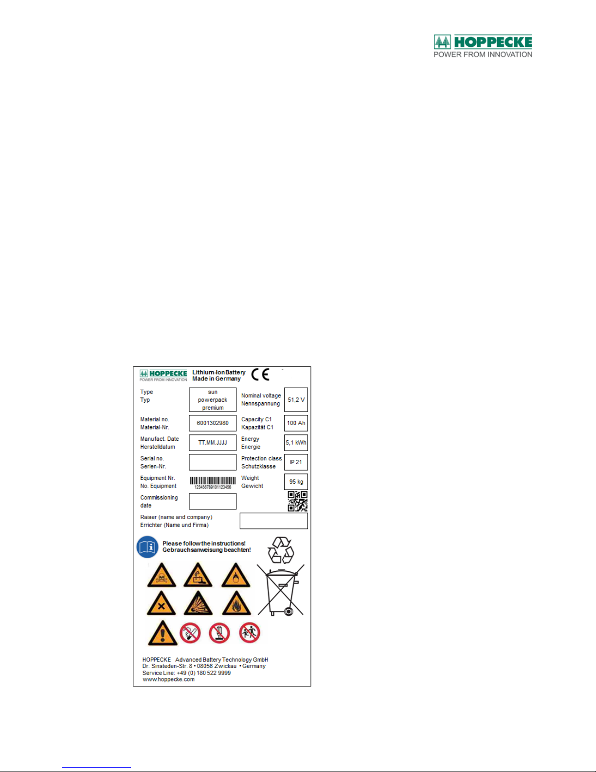
The battery stacks consist of individually connected lithium iron phosphate battery cells (see
also nameplate for the system and battery stack in Figure 2 and Figure 3). The two battery
stacks are connected in series. This yields a storage capacity of approx. 5 kWh or 7.5 kWh
at a nominal voltage of 51.2 V.
Figure 2: Example of a battery system nameplate
Page 18

Sun|powerpack premium battery system
BA_sun_power_pack_LiOn_en_V1.05.docx V1.05 (20/07/2017) 6140203036 18
Figure 3: Nameplate and safety instructions on the battery stack
Note:
The battery system should be operated only with approved battery inverters / battery chargers.
The nominal battery voltage is 51.2 V, and communication between the battery inverter / battery
charger and the battery system takes place via a data interface (CANOpen).
4.1. Hints for sizing of the system
The battery system communicates with the battery inverter and therefore realizes an
automatic system operation. It is not required to operate the system manually. However for
system sizing and operation the following hints shall be observed:
Note:
Sizing of the entire system including installed PV and inverter power and the operation scheme of
the system (electrical loads) must realize occasional battery full charges (state of charge – SOC
= 100%).
Note:
Sizing of the entire system shall consider the usage of 80% to 90% of the nominal battery
capacity.
Page 19
Storage
BA_sun_power_pack_LiOn_en_V1.05.docx V1.05 (20/07/2017) 6140203036 19
5. Storage
This chapter pertains to the storage of the battery system components at the premises of
wholesale dealers, installation agencies or end customers. For installation agencies or end
users, the individual system components should be stored only temporarily until the
installation of the battery system.
5.1. Intact, undamaged batteries and batteries at the end of their
service life
Do not store the battery system together with flammable substances. It is recommended to
have a smoke detector at the place of installation. Protect from exposure to sunlight,
sources of radiation and heat sources. Store it in a dry and cool place.
HOPPECKE recommends storage in the original packaging.
ATTENTION!
A maximum of up to two battery stacks in original packaging may be kept or stored such that they
are stacked on one another.
Instructions for wholesale dealers and installation agencies:
Coordinate other safety measures with the local authorities and loss insurers.
Storage period:
For ambient temperatures of -20°C to 35°C the battery stacks may be stored up to 6
months. If the maximum storage period is exceeded, please contact HOPPECKE Service.
ATTENTION!
The battery stacks should be charged only when they are installed in the system and during
normal operation.
5.2. Defective batteries
WARNING!
Defective batteries may reach conditions that are critical to safety. As a consequence of this, the
batteries may burst, ignite and hazardous decomposition products may be formed (see also
chapter 3).
Instructions for specialists: Damaged batteries must be surrounded with dry sand, chalk
powder (CaCO3) or Vermiculite. If possible, they should be stored outside the buildings.
They should best be stored in a sealed, shock-proof and fire-proof external packaging. The
storage place should be marked and safeguarded with warning signs; in case the battery
causes smoke development the storage place must also be monitored. Make sure to
maintain a safe distance to combustible materials with Li-Ion batteries in any case.
Page 20
Preparing for installation
BA_sun_power_pack_LiOn_en_V1.05.docx V1.05 (20/07/2017) 6140203036 20
6. Preparing for installation
Before you begin with installation, check whether the installation site meets the
requirements (see chapter 6.1).
Keep all necessary tools ready at hand (see chapter 6.2).
6.1. Installation site
The sun|powerpack premium must be installed and operated in a dry and frost-free indoor
room (e.g. utility room or cellar). The installation site must be vibration-free.
WARNING!
The battery system should not be stored, installed or operated in rooms endangered by floods.
CAUTION!
At the installation site maintain a minimum distance of 2 m to flammable items. The battery
system should not be installed on combustible surfaces. Operation in explosive zones is not
permissible.
CAUTION!
The battery system must be installed in such a manner that the battery stacks inside the battery
system are in an upright position. For the installation of the battery system on a wall it must be
ensured that the wall concerned has adequate load-bearing capacity (see also specifications of
the weight in chapter15.1).
ATTENTION!
Keep a distance of at least 0.3 m at the installation site between adjacent sun|powerpack
premium battery systems as well as other items, side walls or floors. Observe and follow the
manufacturer's specifications for the minimum distances to the battery inverter or other
equipment installed in the room.
ATTENTION!
In order to dissipate waste heat optimally, the battery system should not be covered up or
concealed.
Note:
While installing batteries, the respective national building regulations must be observed and
followed.
Note:
The max. installation height of the battery system is 1.20 m (distance between the floor and the
bottom edge of the battery system).
Note:
The battery system is fixed to a wall at the installation site. Only the wall mount supplied along
with the battery should be used for this purpose.
Page 21

Preparing for installation
BA_sun_power_pack_LiOn_en_V1.05.docx V1.05 (20/07/2017) 6140203036 21
Note:
It must be possible to lock with a door the room in which the battery system is located. The door
must be kept closed. HOPPECKE recommends an automatically closing door or an automatic
door closer.
Note:
A smoke detector must be installed on the ceiling at the installation site and above the battery
system.
6.2. Tools and Equipment
The following tools are required for installation:
Allen key 4 mm for fixing the battery stacks in the housing and connecting the housing
with screws to the wall mount
Box spanner 8 mm / torque wrench for fixing the protective earth conductor to the
grounding point of the housing.
Tools and installation material for the wall mount.
Insulated torque wrench 10 mm for connecting the terminal nuts with screws to the
battery stacks.
Drilling machine (with drill bits for appropriate subsurface of the mounting wall)
Spirit level
Page 22
Installation
BA_sun_power_pack_LiOn_en_V1.05.docx V1.05 (20/07/2017) 6140203036 22
7. Installation
The following sections of this chapter describe the installation and commissioning of the
battery store system.
7.1. Assembling and installing the housing
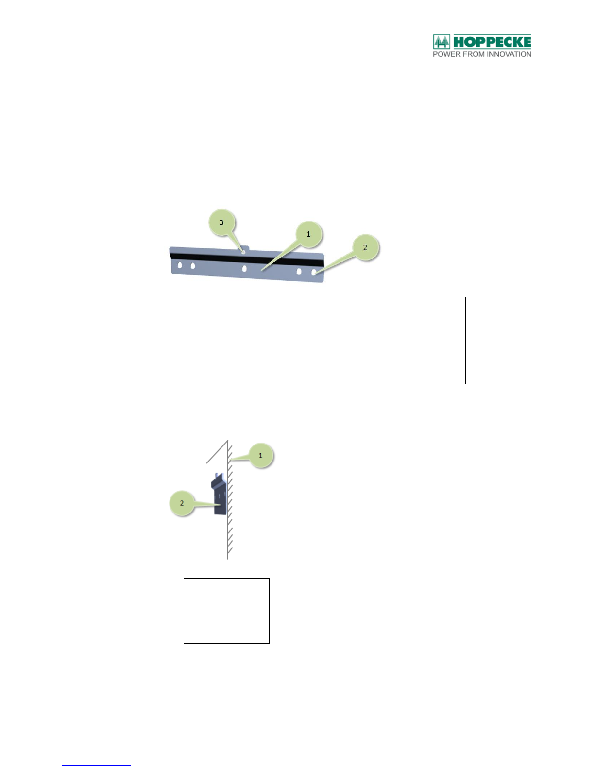
1. Transfer the position of the boreholes with a pencil to the intended position of the
battery system on the installation wall. Use a spirit level in order to align the
subsequent position of the wall mount (see also Figure 4).
No.
Description
1
Wall mount
2
Borehole for wall mounting
3
Threaded borehole for attaching the housing to the wall mount
Figure 4: Boreholes in the wall mount
2. Fix the wall mount with appropriate screws. The wall mount must lie flush with the
mounting wall (see also Figure 5).
No.
Description
1
Mounting wall
2
Wall mounting
Figure 5: Installing the wall mount
Page 23
Installation
BA_sun_power_pack_LiOn_en_V1.05.docx V1.05 (20/07/2017) 6140203036 23
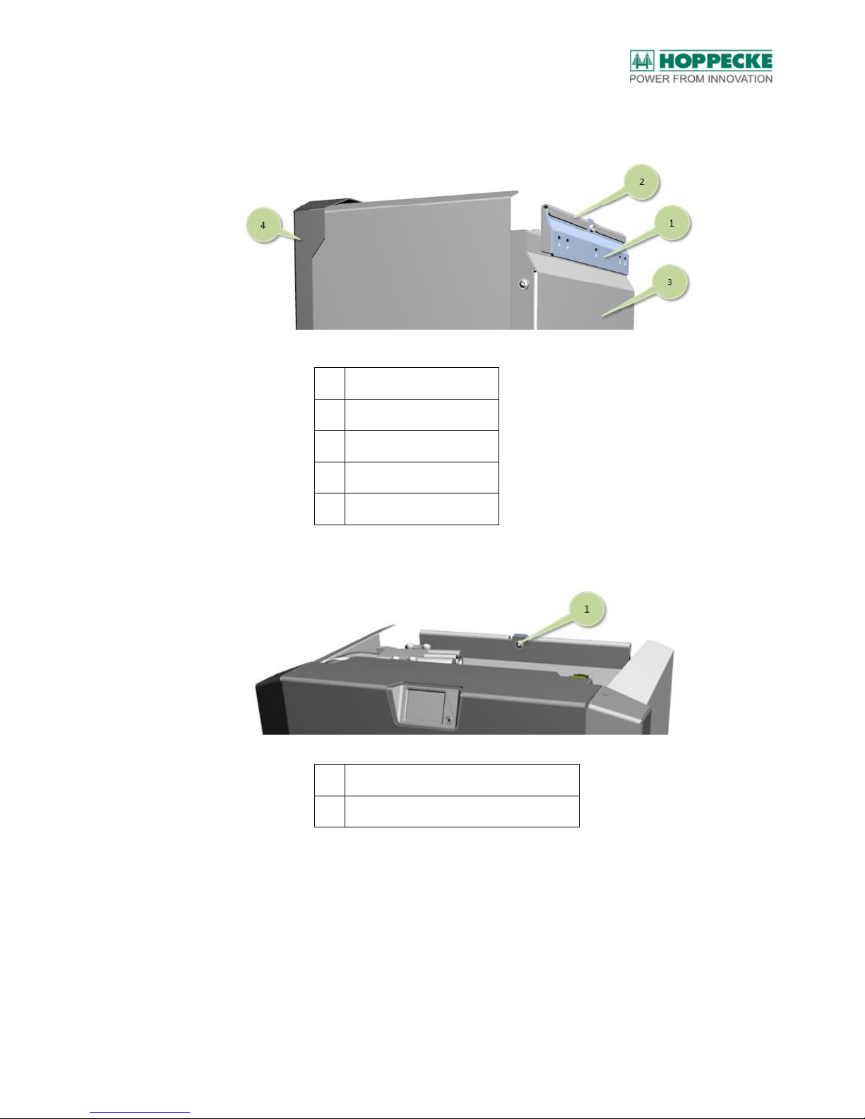
3. Hook the empty housing with the fastening rail fixed on the rear side from the top
into the wall mount (see Figure 6)
No.
Description
1
Wall mounting
2
Fastening rail
3
Rear side of the housing
4
Housing cover
Figure 6: Suspended housing
4. Fix the Allen screw (M6) supplied with the housing to the wall mount (see Figure 7).
No.
Description
1
Fixing the wall mount with the housing
Figure 7: Fixing the wall mount and the housing
Page 24
Installation
BA_sun_power_pack_LiOn_en_V1.05.docx V1.05 (20/07/2017) 6140203036 24
7.1.1. Grounding the housing
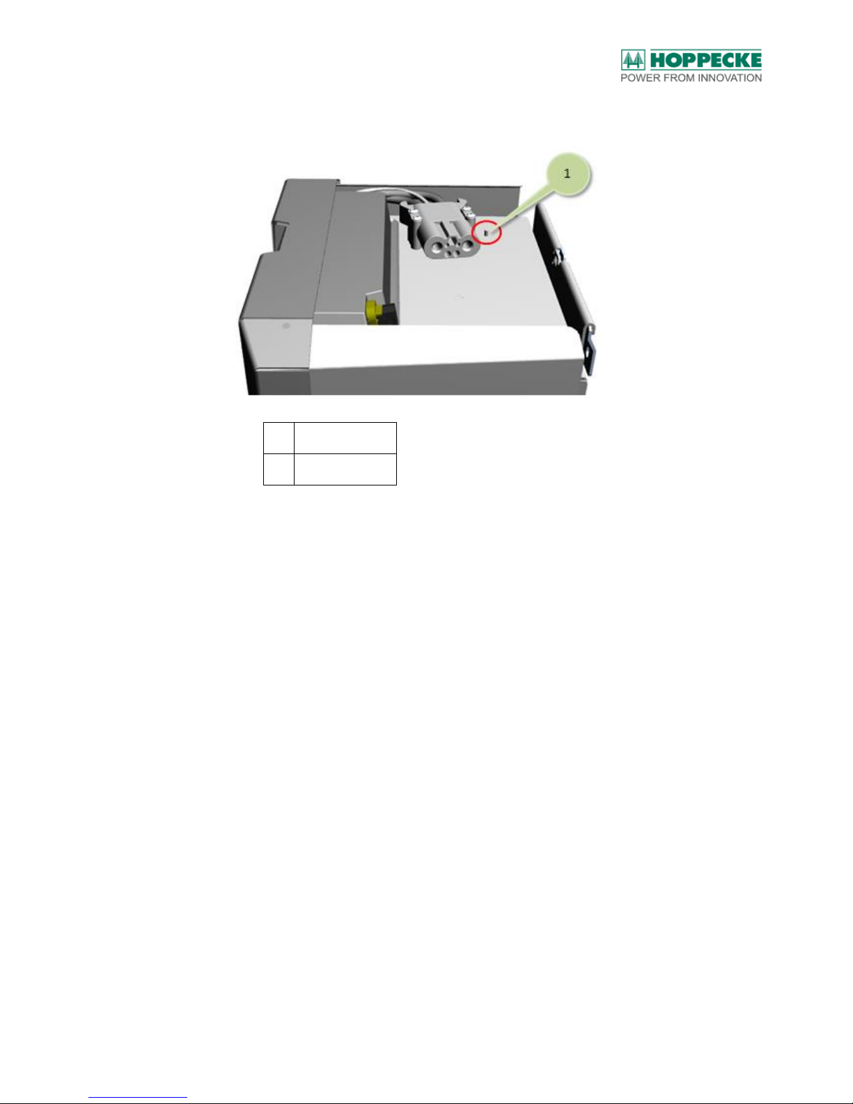
1. The grounding point is located on the top of the housing (see Figure 8).
No.
Description
1
Grounding point
Figure 8: Grounding point
2. Fix the protective ground conductor with a ring cable lug to the grounding point on
the housing. Use the spring washer and nut supplied for this purpose. The
tightening torque is 12 Nm. Use a suitable protective ground conductor with
appropriate cross-section (not included in the scope of supply).
Page 25
Installation
BA_sun_power_pack_LiOn_en_V1.05.docx V1.05 (20/07/2017) 6140203036 25
7.2. Installing the battery stacks
Note:
The system can be operated only when it is completely equipped, i.e. with the two battery stacks
supplied / fix assigned (identical capacity and nominal voltage). Check this based on the
information on the nameplate of the battery stacks.
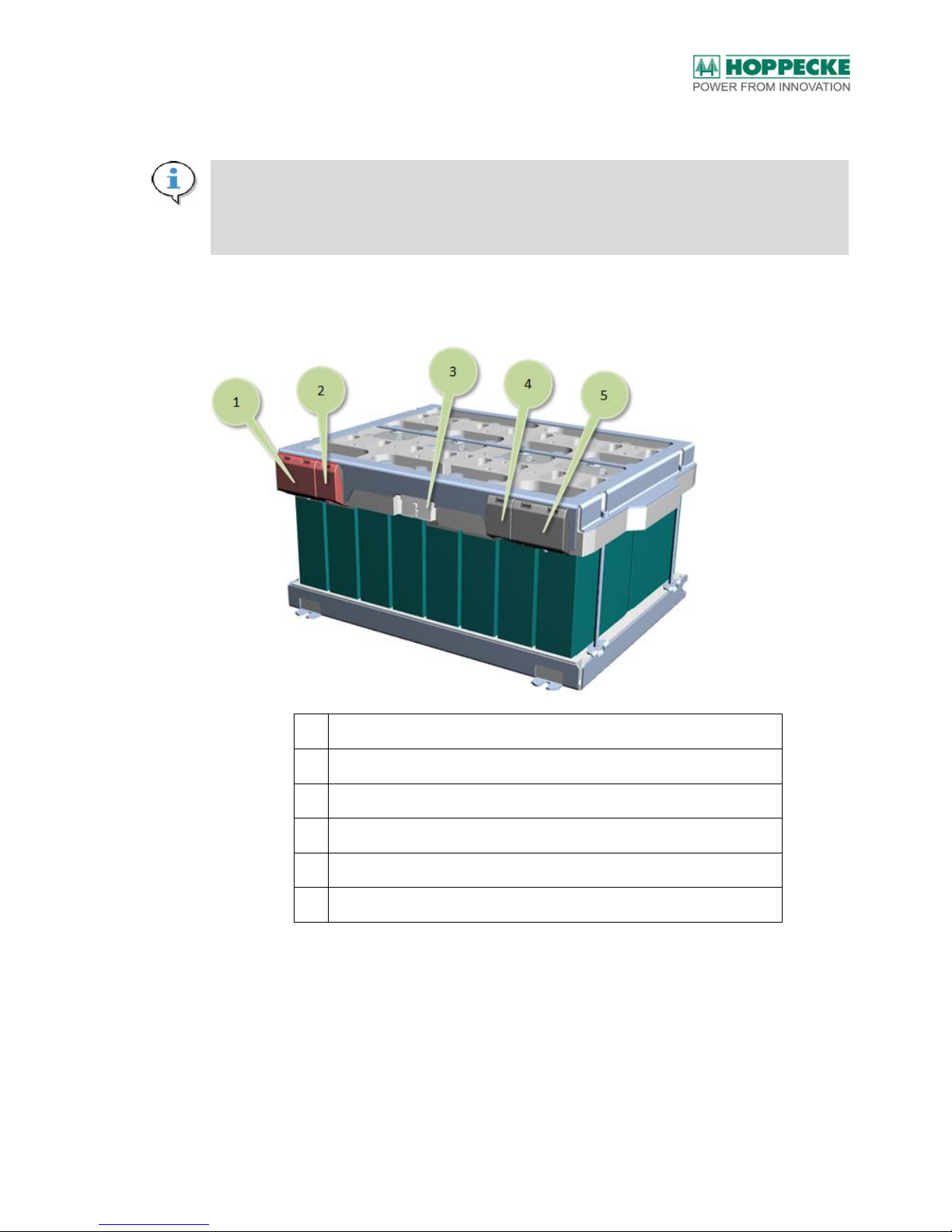
1. The battery stacks are packed in separate cartons. The cartons should not be
opened with pointy tools or objects (see also Figure of the battery stack in Figure 9).
No.
Description
1
Cover for safety fuse (do not remove)
2
Cover for connecting the plus terminal
3
Connection for the cable harness to the battery management system
4
Cover for connecting the minus terminal
5
Cover for minus terminal (do not remove)
Figure 9: Battery stack - Connections
Page 26
Installation
BA_sun_power_pack_LiOn_en_V1.05.docx V1.05 (20/07/2017) 6140203036 26
2. Check the battery stacks for visible signs of damage.
WARNING!
The battery stacks with apparent signs of damage must not be installed or connected to the BMS!
CAUTION!
The battery stacks and the battery cells that they contain should not be disassembled or opened
under any circumstances.
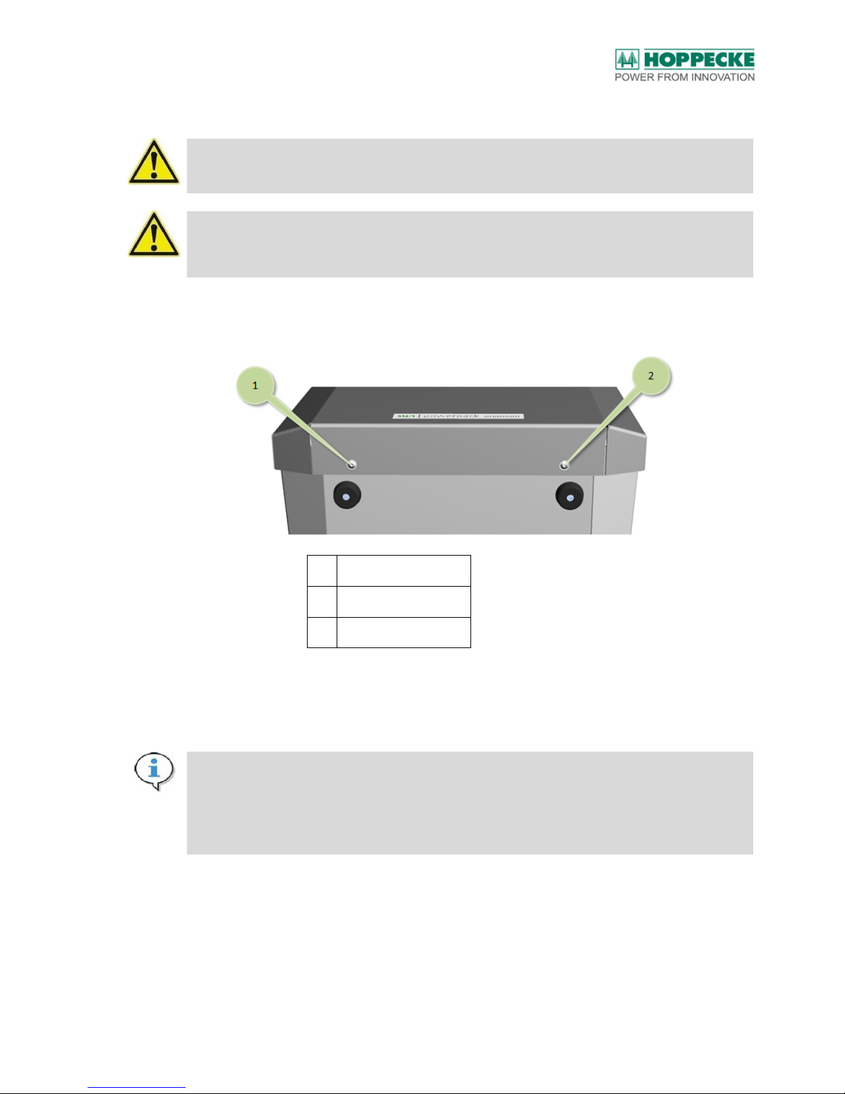
3. Remove the cover of the housing. To do this, loosen the Allen screws at the bottom
of the cover (see Figure 10).
No.
Description
1
Left fastening screw
2
Right fastening screw
Figure 10: Fastening screws on the cover
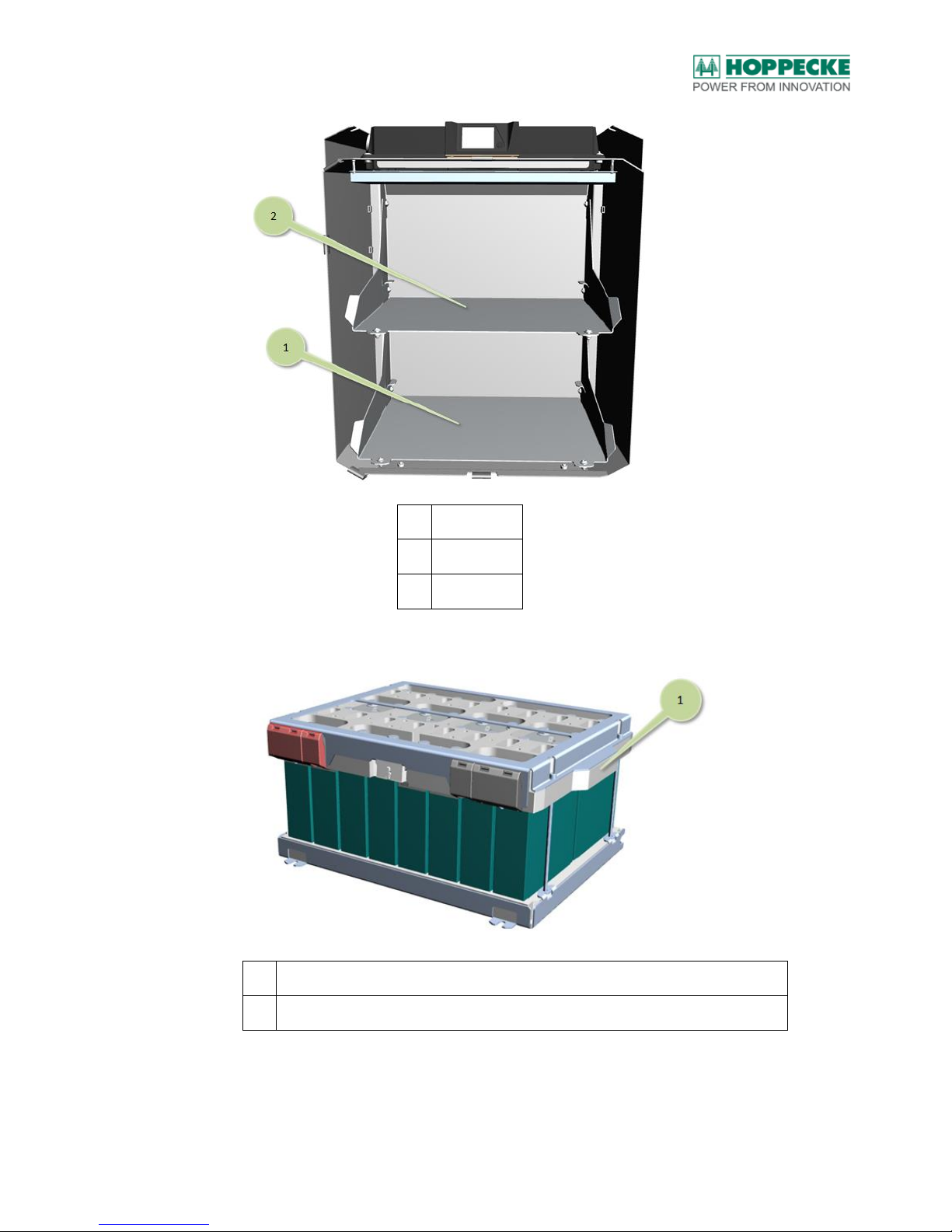
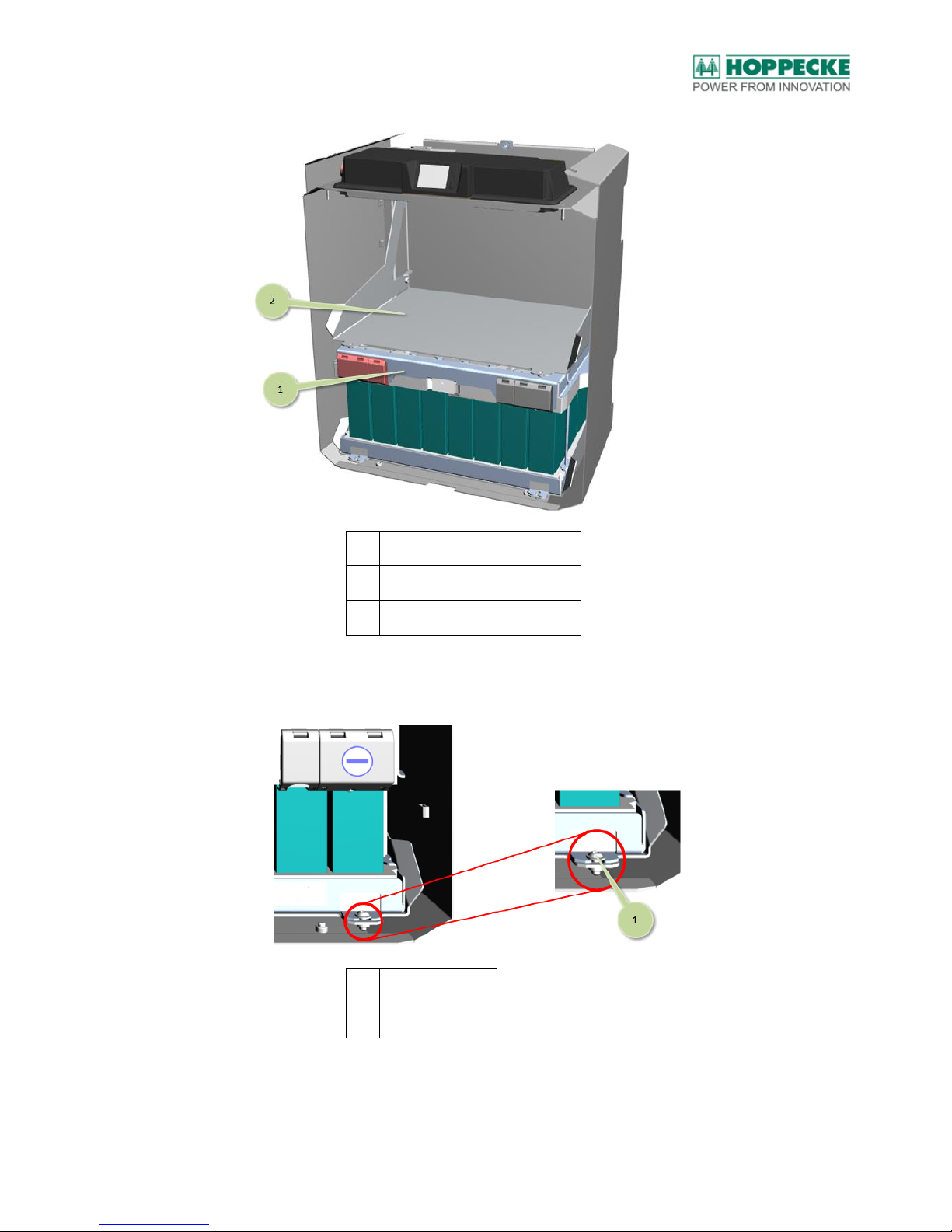
4. Push the battery stacks one after the other into the housing of the battery system.
Use the carry grips fixed on the sides to lift the battery stack (see Figure 11 and
Figure 12). Begin with the lower level (see Figure 13).
Note:
Each battery stack is marked on the front side, among others, with a serial number. Each of the
housing levels is also marked with the serial number of the battery stack assigned to it (see the
inside of the housing) to know which battery stack needs to be installed in each level of the
housing.
Page 27
Installation
BA_sun_power_pack_LiOn_en_V1.05.docx V1.05 (20/07/2017) 6140203036 27
No.
Description
1
Lower level
2
Upper level
Figure 11: Upper and lower levels in the housing
No.
Description
1
Carry grip of the battery stack (see the left and right side on the battery stack)
Figure 12: Battery stack – Carry grip
Page 28
Installation
BA_sun_power_pack_LiOn_en_V1.05.docx V1.05 (20/07/2017) 6140203036 28
No.
Description
1
Lower level with battery stack
2
Upper level
Figure 13: Battery stack in the housing
5. Fix the battery stack with the screws supplied along with it on the lower level (see
Figure 14).
No.
Description
1
Fastening screw
Figure 14: Fixing the battery stack
Page 29
Installation
BA_sun_power_pack_LiOn_en_V1.05.docx V1.05 (20/07/2017) 6140203036 29
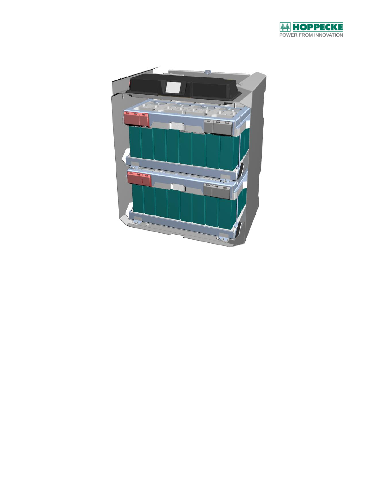
6. Push the second battery stack into the upper level of the housing (see Figure 15)
and fix it to the upper level.
Figure 15: Housing with two battery stacks
Page 30
Installation
BA_sun_power_pack_LiOn_en_V1.05.docx V1.05 (20/07/2017) 6140203036 30
7.3. Connecting the battery stacks electrically
DANGER!
The battery stacks with apparent signs of damage should not be connected to the BMS (see also
chapter 3.7.1)!
Defective batteries may reach conditions that are critical to safety. As a consequence of this, the
batteries may burst or catch fire and hazardous decomposition products may be formed. In case
liquid or gaseous substances are leaking, leave the room immediately and alert the fire brigade
(see also chapter 3.6).
WARNING!
The battery terminals or the associated connecting cables must not be grounded.
WARNING!
Use only insulated tools (see chapter 6.2).
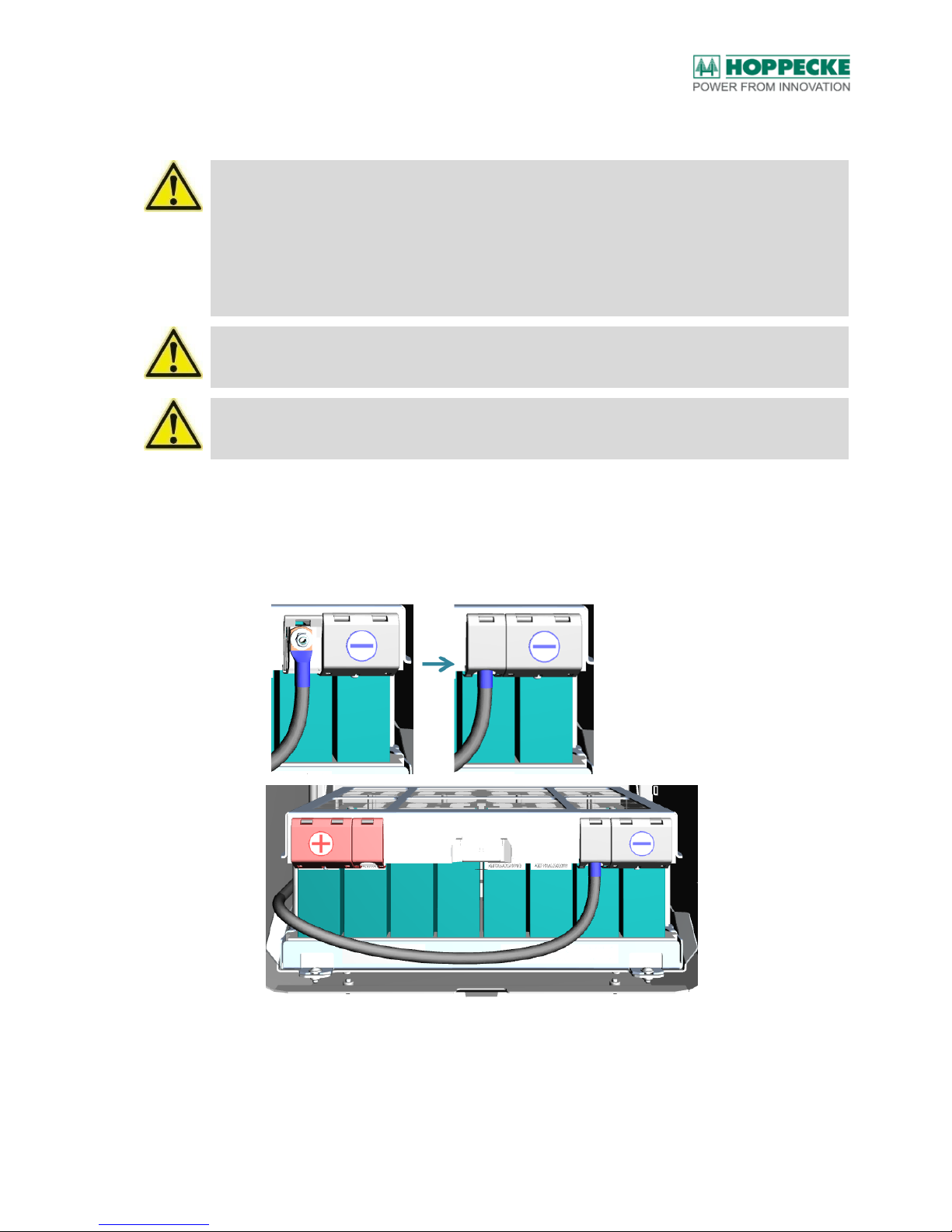
1. Connect the minus terminals of the lower battery stack (right side) with the
connecting cable marked in blue colour.
2. To install the connector, the plastic cover of the battery stack must be folded up.
3. Fasten the connector with a flat washer and M6 nut to the screw terminals of the
battery stack. The tightening torque is 5 Nm (see Figure 16).
Figure 16: Screw connection of the minus terminal at the lower battery stack
Page 31
Installation
BA_sun_power_pack_LiOn_en_V1.05.docx V1.05 (20/07/2017) 6140203036 31
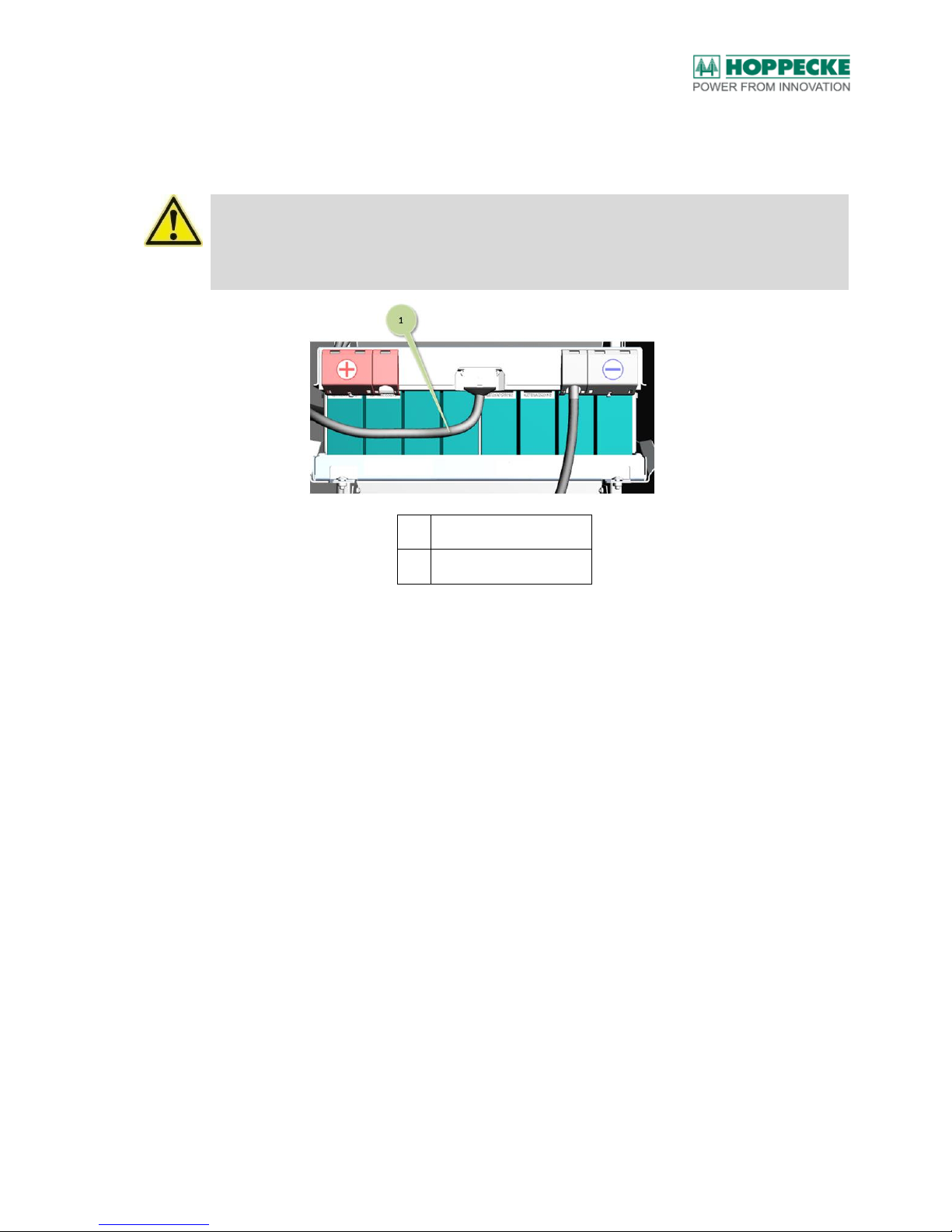
4. Connect the cable of the battery management system with the connection at the
upper battery stack. The associated cable harness is prepared accordingly (see
Figure 17)
ATTENTION!
The cable harnesses for the battery management system are prepared and kept ready, and
based on their length, they fit only to the upper or lower battery stack. These cables should not
be interchanged.
No.
Description
1
Connection to the BMS
Figure 17: BMS connection at the lower battery stack
5. For serial connection of the two battery stacks, the plus terminal of the battery stack
in the lower level (left side) must be connected to the minus terminal of the battery
stack in the upper level (right side). To do this, use the prepared and ready-made
connecting cable (both ends are marked in black colour). To install the connector,
the respective plastic covers of the battery stack must be folded up.
6. Fasten the connector with a flat washer and M6 nuts to the screw terminals of the
battery stacks (see Figure 18). The tightening torque is 5Nm.
Page 32

Installation
BA_sun_power_pack_LiOn_en_V1.05.docx V1.05 (20/07/2017) 6140203036 32
No.
Description
1
Serial connection of the lower and upper battery stacks
Figure 18: Serial connection of the batteries
7. Connect the cables of the battery management system with the connection at the
upper battery stack. The associated cable harness is prepared and kept ready
accordingly (see Figure 19).
No.
Description
1
Connecting the Battery Management System to the upper battery stack
Figure 19: Connecting the BMS to the upper battery stack
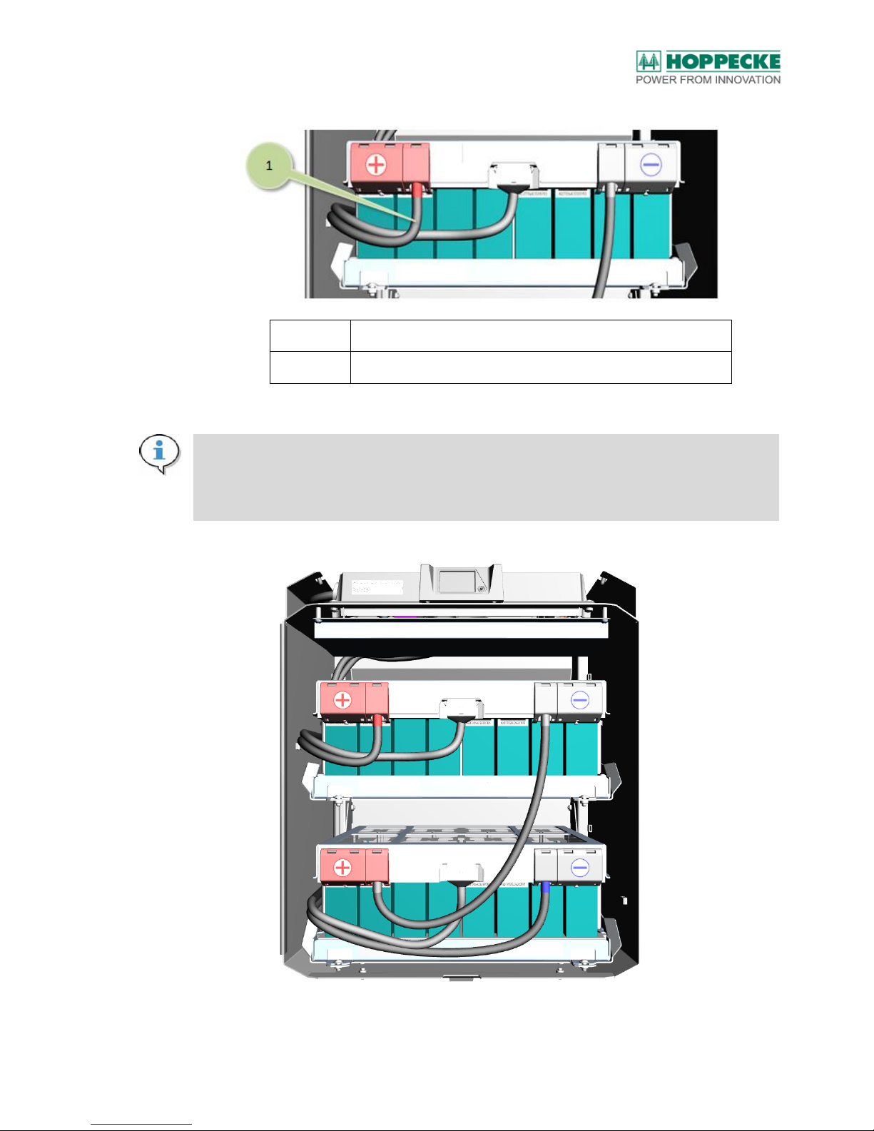
8. Connect the plus terminal of the upper battery stack to the associated black
connecting cable with marked in red colour (see Figure 20 and Figure 21).
Page 33
Installation
BA_sun_power_pack_LiOn_en_V1.05.docx V1.05 (20/07/2017) 6140203036 33
No.
Description
1
Connecting the battery plus terminal to the upper battery stack
Figure 20: Connecting the plus terminal to the upper battery stack
Note:
The voltages and temperatures of the individual battery cells are acquired via the cables in the
cable harness. This data is needed urgently for trouble-free operation and management of the
system.
Figure 21: Battery stacks with connections
Page 34

Installation
BA_sun_power_pack_LiOn_en_V1.05.docx V1.05 (20/07/2017) 6140203036 34
7.4. Connecting the battery inverter
ATTENTION!
The battery system must be connected only to battery inverters that have been approved by
HOPPECKE.
For connection to the battery inverter approved for the HOPPECKE sun|powerpack
premium (see Table 1). These inverters meet among others the requirements of galvanic
isolation necessary:
Manufacturer
Device
Additional information:
SMA
Sunny Island
6.0H / 8.0H
When using the Sunny Island 8.0 in off-grid applications,
HOPPECKE recommends the sun|powerpack premium
7.5/48 battery store system or larger.
SMA
Sunny Island
3.0M / 4.4M
---
Table 1: Overview of compatible battery inverters
ATTENTION!
Observe and follow the sequence of the electrical connection strictly!
Note:
Switch off the battery inverter before connecting the battery connecting cable. Follow the
information provided in the manufacturer's documentation.
1. First connect the battery connecting cable to the battery inverter. Follow the
information provided in the manufacturer's documentation.
2. Connect the communication cable to the appropriate connection on the inverter.
Follow the information provided in the manufacturer's documentation.
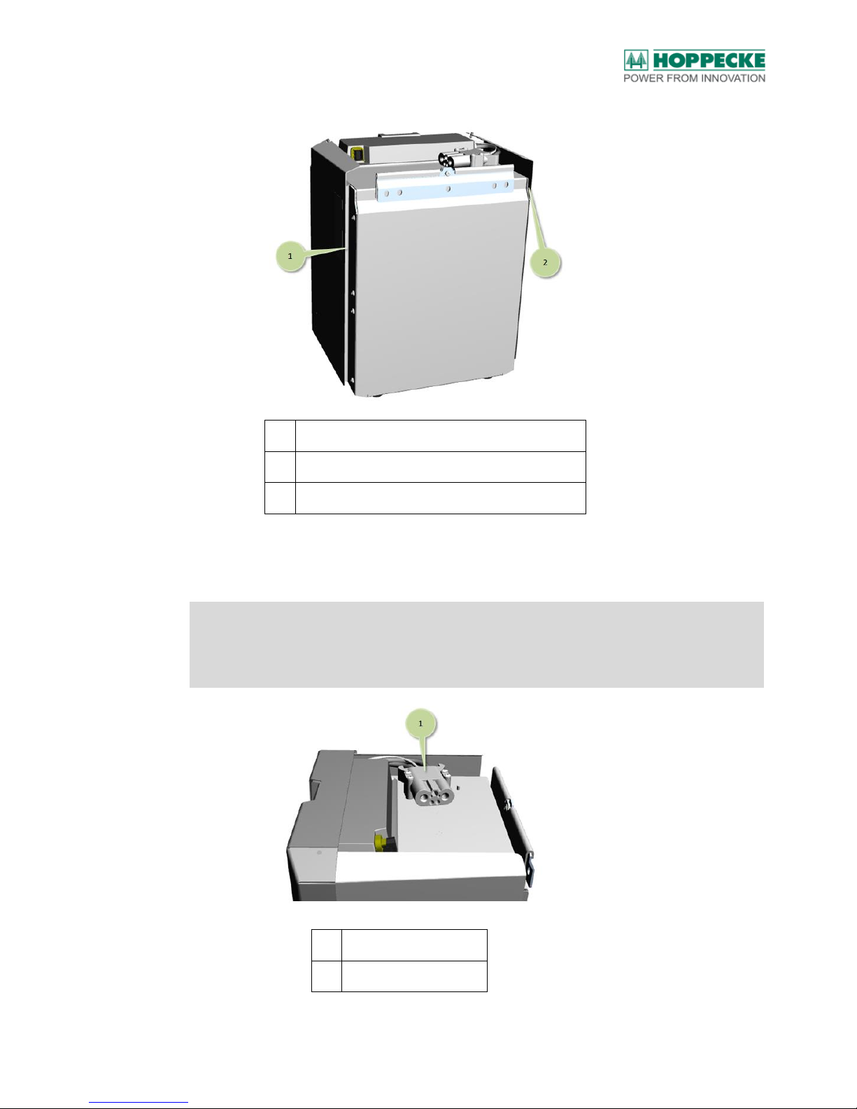
3. Route the battery connecting cable and the communication cable to the battery
system. If the battery inverter is placed below or beside the battery system, the
cables may be routed in the left or right opening (see Figure 22) to the top of the
battery system (connecting cable up to 50mm2 cross section for plus and minus).
Page 35
Installation
BA_sun_power_pack_LiOn_en_V1.05.docx V1.05 (20/07/2017) 6140203036 35
No.
Description
1
Opening for routing the battery connecting cable
2
Opening for routing the battery connecting cable
Figure 22: Openings for the battery connecting cable
4. Insert the connector of the battery connecting cable in the connection jack on the
top of the battery system (see Figure 23)
7.
Note:
The connector has to be pushed into the connection jack up to the stop. Insertion is made
intentionally stiff. The connection of the communication cable (CAN bus) is also located in the
connector of the DC connection jack.
No.
Description
1
Battery connection jack
Figure 23: Battery connection jack
Page 36
Installation
BA_sun_power_pack_LiOn_en_V1.05.docx V1.05 (20/07/2017) 6140203036 36
7.5. Commissioning
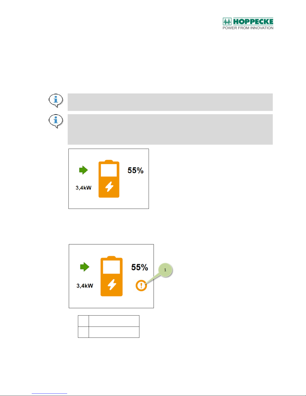
Switch the battery inverter on. With successful assembly and installation and correct
connection to the battery inverter, the current state of charge is shown in the display unit of
the battery system in percent and the instantaneous charging or discharging power is
displayed (see Figure 24). In charging mode, the arrow points in the direction of the battery
icon. In the discharging mode, the arrow points away from the battery icon. With this, the
installation has been completed successfully.
Note:
Configure the battery inverter according to the manufacturer's specifications.
Note:
If the battery is in deep discharge condition, after restarting the BMS, there are 3 minutes left to
set up the charging current. If the BMS detects a charging current within the 3 minutes time, the
BMS remains active and the battery may be charged fully.
Figure 24: Display unit (Example of standard display)
If a warning or error condition is present, this is displayed with an exclamation mark
(Warning) or an "X" symbol (Error) in the display unit (see Figure 25). See also chapter 12.
No.
Description
1
Icon for active warning
Figure 25: Display unit (example for symbolising an active warning)
Page 37
Installation
BA_sun_power_pack_LiOn_en_V1.05.docx V1.05 (20/07/2017) 6140203036 37
7.6. Final work
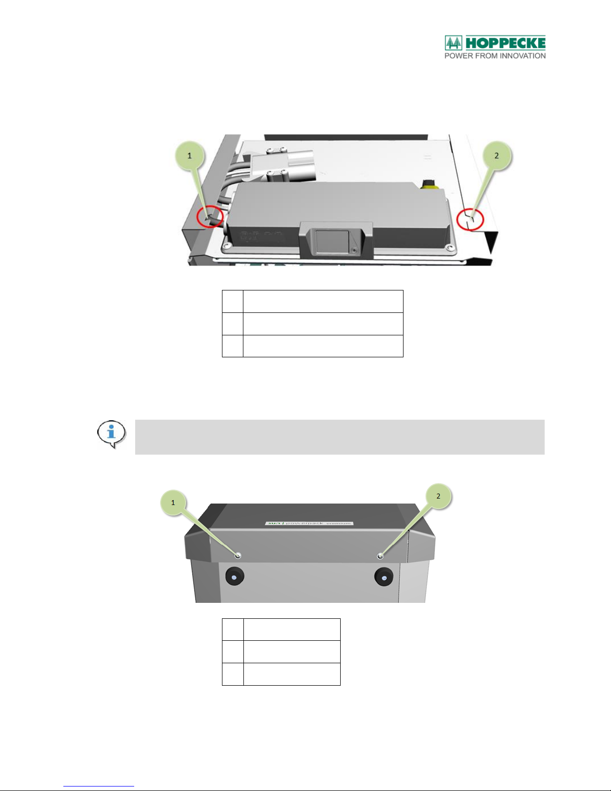
1. Hook the cover of the battery system into the openings at the top of the housing
(see Figure 26).
No.
Component
1
Left opening for fastening the cover
2
Right opening for fastening the cover
Figure 26: Openings for fastening the cover
2. Press the cover against the bottom side of the housing. Fasten the Allen screws at
the bottom of the cover (see Figure 27)
Note:
Owing to the peripheral gasket on the housing, pressing the cover may be somewhat difficult.
No.
Description
1
Left fastening screw
2
Right fastening screw
Figure 27: Fastening the cover
Page 38

Installation
BA_sun_power_pack_LiOn_en_V1.05.docx V1.05 (20/07/2017) 6140203036 38
3. Stick the supplied sealing sticker on the cover and housing (see Figure 28)
No.
Description
1
Sealing sticker
Figure 28: Sealing of housing
4. Enter the date of commissioning and the details of the installation engineer on the
nameplate of the battery system (Name and Company). The nameplate is located
on both sides of the housing (see sample in Figure 29). Stick the protective foil over
the nameplate afterwards.
Figure 29: Nameplate – Sample
5. Certify proper assembly and installation of the battery store system in the
appropriate form (see chapter 19.2)
Page 39

Registering the battery system
BA_sun_power_pack_LiOn_en_V1.05.docx V1.05 (20/07/2017) 6140203036 39
8. Registering the battery system
For battery systems in Germany only: For the fair value replacement warranty in the context
of the German KfW sponsorship programme for renewable energy "Storage" (Programme
no. 275), the battery system must be registered immediately, but latest within two weeks
after commissioning. For this purpose, you may choose between on-line registration
(https://register.hoppecke-batterien.de/) and registration via telephone at 02963 61-526
(Mon.-Fri. 09:00 AM - 4:00 PM).
You may download the current terms and conditions for warranty from the homepage of
HOPPECKE at www.hoppecke.com.
Page 40
Operating the battery system
BA_sun_power_pack_LiOn_en_V1.05.docx V1.05 (20/07/2017) 6140203036 40
9. Operating the battery system
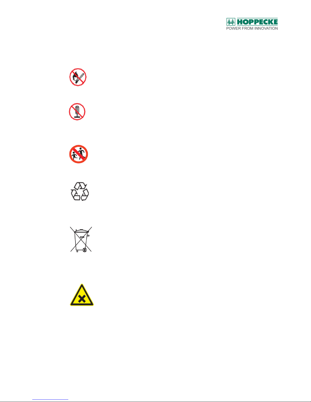
Please make sure to observe and follow the warning and safety instructions given on the
nameplate. The meaning of these instructions is explained in the following:
Avoid open flames, embers or sparks near the battery system.
Do not disassemble or open the battery system (with the exception of assembling or
disassembling the system by an electrician)
Keep children away from the battery system.
Used batteries that have the Recycling icon, are reusable commodities and should not be
disposed of in household waste.
According to this marking, batteries and / or electronic components should not be added to
household waste. Returning and recycling the batteries must be agreed upon with the
manufacturer and ensured.
Warning against substances harmful to health (with release of gases or liquid electrolyte).
With proper assembly and installation, and during regular operation, no liquids or gases are
released.
Page 41
Operating the battery system
BA_sun_power_pack_LiOn_en_V1.05.docx V1.05 (20/07/2017) 6140203036 41
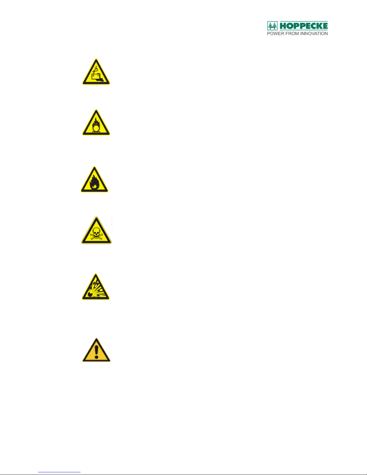
General hazard information on batteries
Warning against oxidising substances. In case of fire, the constituents of the battery (cells)
get oxidised.
Warning against flammable substances.
Warning against toxic substances. With proper assembly and installation, and during regular
operation, no liquids or gases are released.
Warning against explosive substances by release of gases, e.g. by mechanical damage to
the cells. With proper assembly and installation, and during regular operation, no liquids or
gases are released
Observe and follow the instructions for transport.
Page 42

Operating the battery system
BA_sun_power_pack_LiOn_en_V1.05.docx V1.05 (20/07/2017) 6140203036 42
9.1. Safety Functions
The battery management system offers various safety functions in order to ensure safe and
high-performance operation over the specified service life. Safety functions in accordance
with EN62108 are listed in the following (see Table 2).
Name
Function
Classification
SF1
Shutting down the charging current with impending
overcharging of one or more cells
SIL1
Table 2: Safety function
The Battery Management System (BMS) controls the battery charging and discharging
process automatically. For this purpose, the BMS communicates with the battery inverter via
a data interface (CAN bus). The maximum permissible values of the charging and
discharging current and the current state of charge are communicated to the battery inverter
via this data interface. The battery inverter is responsible for managing the operation based
on the load or consumption situation as well as the energy generation of the PV generator.
The BMS controls the battery system automatically. It is not possible for the (end) user to
intervene manually. The display unit is used only to display information on the instantaneous
state of the battery system as well as general information (see below). The information
output on the display unit can also be retrieved with the help of the button at the bottom right
of the display unit.
9.2. Display Unit
Note:
The display unit is switched on using the button at the bottom right corner. Moreover, the
information displayed can be switched with the help of this button. In order to conserve battery
power, the display unit is switched off after about 60 sec. (after the previous button operation). If
there is an active warning or an error present, the display remains switched on.
The following information can be output on the display unit by pressing a button:
1. Main screen:
State of charge (SOC = State of Charge) in %.
Instantaneous battery charging or discharging power in kW
Additional icon if there is an active warning or active error
2. Warnings / Errors (only if an active warning or error message is present):
Type of message (warning or error)
Error description
3. System:
Serial number of the battery system
Serial number of the BMS
Nominal voltage of the systems (48 V)
Nominal capacity of the system (e.g. 5 kWh)
Hardware version of the BMS
Software version of the BMS
Inverter configured (e.g. SMA)
Page 43
Operating the battery system
BA_sun_power_pack_LiOn_en_V1.05.docx V1.05 (20/07/2017) 6140203036 43
4. Statistics:
Charged energy in kWh (since commissioning)
Discharged energy in kWh (since commissioning)
Cycles (since commissioning)
5. Info / Instantaneous values:
Voltage
Current
Current battery temperature
State of charge (SOC) in %
State of health (SOH) in %
Current maximum cell temperature present
Current minimum cell temperature present
Current maximum cell voltage
Current minimum cell voltage
Error Code (F)
Warning Code (W)
9.3. Operating states
The following operating states of the battery are possible:
Operation (Active): All functions and data communication with the battery inverter are
active.
Off (Inactive): The battery store is switched off by pulling the battery connecting cable. The
CAN communication is stopped and the BMS interrupts the DC link to the battery inverter in
the charging and discharging direction of current. The display unit cannot be activated. No
current can be drawn from the battery. This state is suitable for storing or decommissioning
the battery system.
Note:
For specialists: By pulling the cable attached to the service interface the battery system is also
switched off.
Deep Discharge Protection: As soon as a specific battery cell voltage has been reached,
the BMS issues a warning. If the BMS is restarted before the expiry of one day during the
presence of the warning, the BMS detects the error "Deep discharge" and shuts down. In
order to prevent damage to the battery, the BMS shuts down when a certain critical battery
cell voltage is undershot.
Note:
The BMS switched the system automatically to the inactive mode if the batteries are threatened
by deep discharge. Thus, the BMS ensures that adequate residual energy remains in the battery
in order to initiate the next recharging operation.
Page 44
Operating the battery system
BA_sun_power_pack_LiOn_en_V1.05.docx V1.05 (20/07/2017) 6140203036 44
Note:
If the battery is in deep discharge condition, after restarting the BMS, there are 3 minutes left to
set up the charging current. If the BMS detects a charging current within the 3 minutes time, the
BMS remains active and the battery may be charged fully.
In the case of deeply discharged batteries, the DC link cable must be pulled out and then
plugged in again immediately. Over and above this, the battery must be charged within 3
minutes so that the normal operating mode can be reached (for this purpose, see also the
operating manual of the battery inverter).
Fault: If overshoot of the operating limits or a BMS internal error has been identified, then
depending on the respective error, the semiconductor switch is opened in order to interrupt
the flow of current in the charge and / or discharge direction. The error codes are described
in chapter 12.
Note:
in case of critical errors, the battery system is disconnected from the battery inverter via an
electromechanical switch. The battery system cannot be operated any longer (see also the
appropriate error message in chapter 12). In this case, contact the installation engineer or
HOPPECKE Service.
Page 45

Maintenance and Care
BA_sun_power_pack_LiOn_en_V1.05.docx V1.05 (20/07/2017) 6140203036 45
10. Maintenance and Care
Since the battery management system (BMS) in the battery system monitors the battery
cells continuously and in case of an error, disconnects the battery system from the battery
inverter, regular maintenance of the system is restricted to visual inspection.
Note:
Maintain and check the smoke detector at the installation site in accordance with the
manufacturer's specifications.
10.1. Cleaning
Wipe off the system occasionally with a cloth slightly moistened with water.
10.2. Repair Work
Repair of the battery system is not allowed. Depending on the defect it might be necessary
to replace the battery management. This must only be carried out by an electrician or
HOPPECKE Service personnel (refer to extra documentation).
10.3. BMS software update
The software in the BMS can be updated, if needed, by the installation engineer or
HOPPECKE Service.
Page 46

End of service life
BA_sun_power_pack_LiOn_en_V1.05.docx V1.05 (20/07/2017) 6140203036 46
11. End of service life
The BMS determines among others the end of service life of the battery system. In the
process, the calendar-based and usage-based ageing (represented by the calculated SOH state of health as well as the charge / discharge cycles) is taken into consideration. If the
end of service life is reached, the battery system is shut down. The battery then can neither
be charged nor discharged. An appropriate message is output on the display unit. The end
of service life is reached when the SOH is at 0%. In this condition the battery storage
system has left 70% of its initial capacity.
Note:
In case of shut-down on account of end of service life identified, contact HOPPECKE Service.
Page 47

Warning and erorr messages
BA_sun_power_pack_LiOn_en_V1.05.docx V1.05 (20/07/2017) 6140203036 47
12. Warning and erorr messages
In case of an active error, the battery management system interrupts the battery charging /
discharging operation (see overview of error messages in Table 3). Note the hints in column
“Remarks / Measure”.
No.
Code
Meaning
Remarks / Measure
1 1 Overvoltage
Maximum cell voltage
BMS prevents further charging.
Battery discharge possible.
2 2 Undervoltage
Minimum cell voltage
BMS prevents discharging.
Battery charging possible.
3 4 Overtemperature
Cell temperature > 60°C: BMS interrupts
battery operation until system has cooled
off.
4 8 Undertemperature
Cell temperature < 0°C: BMS stops
charging.
Check environmental conditions (5° to
45°C).
5
16
Undertemperature
Minimum cell temperature discharging
< -10°C. BMS interrupts battery operation.
Check environmental conditions (5° to
45°C).
6
32
Overtemperature
BMS temperature > 90°C: BMS interrupts
battery operation until temperature is in an
acceptable range.
7
64
Deep discharge
Switch the BMS on by plugging in the
connection cable to the battery system and
apply the charging current.
8 to 13
128, 256,
512, 1024,
8192,
16384
Hardware error
Electronic error
Do not make use of the battery any longer.
Contact HOPPECKE Service, the BMS
must be replaced.
14
32768
Cell error
Do not make use of the battery any longer.
Contact HOPPECKE Service.
15
65536
Contact Service
Contact HOPPECKE Service, the BMS
must be replaced.
Table 3: Error codes
Note: In case of multiple simultaneous errors the error codes will be summed up. Example:
overvoltage (Code 1) and overtemperature (32) => 1 + 32 = 33.
Page 48

Warning and erorr messages
BA_sun_power_pack_LiOn_en_V1.05.docx V1.05 (20/07/2017) 6140203036 48
The following warnings do not lead to the battery system being shut down (see Table 4).
Note the hints in column “Remarks / Measure”
No
Code
Meaning
Remarks / Measures
1 1 Watchdog
Warning internal BMS monitoring
Contact HOPPECKE Service
2 4 Deep discharge
Charge battery immediately; do not shut
down, otherwise error code 64
3 8 Data memory
Contact HOPPECKE Service.
4
16
Hardware warning
Contact HOPPECKE Service.
5
8192
End of use
The function of the battery system is not
affected. However the end of service is
coming in the near future.
Table 4: Warnings
Note: In case of multiple simultaneous errors the error codes will be summed up.
Page 49

System expansion
BA_sun_power_pack_LiOn_en_V1.05.docx V1.05 (20/07/2017) 6140203036 49
13. System expansion
The storage capacity may be enhanced subsequently by connecting individual battery
systems in parallel. Only battery systems of identical capacity can be connected in parallel.
Note:
The age difference (from the date of commissioning) between the individual systems to be
connected in parallel should not exceed 24 months.
HOPPECKE offers an appropriate accessories kit for connecting individual battery systems
in parallel. Parallel operation of multiple battery systems must be done only with the help of
original HOPPECKE accessories. Refer to the documentation supplied for setting up and
connecting the accessories kit.
14. Disassembly
You need to carry out the following steps to disassemble the battery store system for repair,
replacement or disposal:
1. Switch off the battery inverter.
2. Pull out the connecting plug on the top of the battery store system.
3. Open the cover of the battery store system.
4. Start from the "top left to the bottom right":
5. Disconnect the terminals of the battery stacks (top left plus terminal, top cable to the
BMS, top right minus terminal, bottom left plus terminal, bottom cable to the BMS,
bottom right minus terminal).
6. Loosen the battery stacks from the mounts (loosen 2 Allen screws of 4 mm each)
7. Remove the battery stacks from the housing and pack them safely in the original
packaging.
8. Loosen the housing from the mount (4 mm Allen screw).
9. Lift the housing from the wall.
10. Pack the housing in the delivery packing.
Page 50

Technical Specifications
BA_sun_power_pack_LiOn_en_V1.05.docx V1.05 (20/07/2017) 6140203036 50
15. Technical Specifications
15.1. System
Dimensions: 600 x 500 x 350mm (H x W x D)
Total weight per system: 5.0 / 48: Ca. 85 kg or 7.5 / 48: Ca. 100 kg
Ambient temperature, operation and storage: +5°C to +45°C
Optimal temperature range during operation: +5°C to +35°C
Relative atmospheric humidity: 0 to 90% (non-condensing)
IP Code: 21
End-of-charge voltage: 56V
Power consumption: Approx. 1 W (CAN – Bus active).
In the switched off condition, the selfconsumption
falls to approx. 10 mW.
Storage period of the battery system of
at least 6 months with subsequent
"Wake Up" possible.
15.2. Battery cell
Technologies: Prismatic cells, lithium iron phosphate (LiFePo)
Nominal capacity: 50 Ah (C3) 5 kWh or 78 Ah (C3) 7.5 kWh system
Nominal voltage: 3.2 V/cell (51.2V battery system)
Charging method: IU (constant current / constant voltage)
Efficiency: 98% (0.5 C – discharge)
15.3. Norms and Standards
DIN EN 62620:2011-05
EN 61427-2
EN 61508
VDE AR 2510-50
UN38.3 (Area of application: Battery stacks)
Page 51
CE Declaration of Conformity
BA_sun_power_pack_LiOn_en_V1.05.docx V1.05 (20/07/2017) 6140203036 51
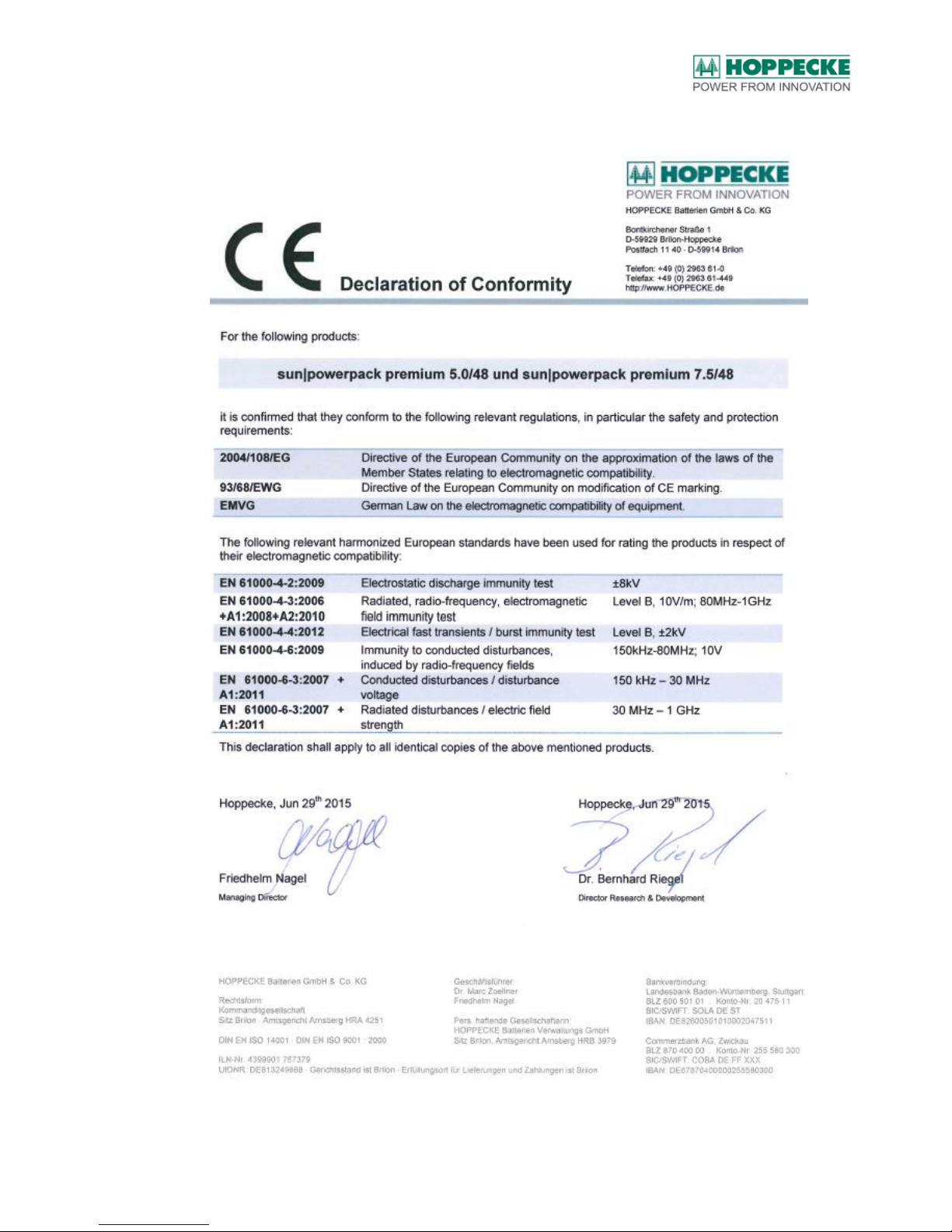
16. CE Declaration of Conformity
Page 52

Abbreviations
BA_sun_power_pack_LiOn_en_V1.05.docx V1.05 (20/07/2017) 6140203036 52
17. Abbreviations
BMS Battery Management System
CAN Controller Area Network
DC Direct Current
DOD Depth of Discharge
Li-Ion Lithium-Ion
SoC State of Charge
SOH State of Health (Available capacity with full charge related to the nominal
capacity)
Page 53

Further information
BA_sun_power_pack_LiOn_en_V1.05.docx V1.05 (20/07/2017) 6140203036 53
18. Further information
/1/ "Operation in stationary lithium solar energy stores - Notes on fire-fighting and technical
assistance", issued by: Federal Association for Solar Industry - Bundesverband Solarwirtschaft (1st
Edition, December 2014). See also under: http://www.solarwirtschaft.de/ .
Page 54

Appendix
BA_sun_power_pack_LiOn_en_V1.05.docx V1.05 (20/07/2017) 6140203036 54
19. Appendix
19.1. Certification of the function of the smoke detector
I certify herewith that a smoke detector has been installed in the ceiling area above the
battery system at the installation site of the battery system. The functionality of the smoke
detector has been tested and the test has been passed. The original of this certification
must remain with the operator of the PV system and kept in safe custody.
Place:_______________________________ , Date: _______________________
Name (Installation Engineer): ____________________ Company:____________________
Signature: ______________________________
19.2. Certification of installation and commissioning
I certify herewith that the requirements of the place of installation have been met and
installation as well as commissioning of the battery system has been done according to the
specifications of this operating manual. The original of this certification must remain with the
operator of the HOPPECKE sun|powerpack premium system and kept in safe custody.
Place:_______________________________ , Date: _______________________
Name (Installation Engineer): ____________________ Company:____________________
Signature: ______________________________
 Loading...