


_____________________________________________________________
Technical Manual
NTP/SINEC H1 LAN Board
Model 7273 and 7273RC
for housing versions
1U / 3U / DIN-Rail
ENGLISH
Version: 08.00 - 01.08.2018
_____________________________________________________________
SET
IMAGE
FIRMWARE
Valid for
Version: 08.xx
Version: 08.xx
Version: 02.xx
Industriefunkuhren

2 / 113 7273 and 7273RC NTP/SINEC H1 LAN Board - V08.00
hopf
Elektronik GmbH
Nottebohmstr. 41 • D-58511 Lüdenscheid • Tel.: +49 (0)2351 9386-86 • Fax: +49 (0)2351 9386-93 • Internet: http://www.hopf.com • E-Mail: info@hopf.com

INPORTANT NOTES
7273 and 7273RC NTP/SINEC H1 LAN Board - V08.00 3 / 113
hopf
Elektronik GmbH
Nottebohmstr. 41 • D-58511 Lüdenscheid • Tel.: +49 (0)2351 9386-86 • Fax: +49 (0)2351 9386-93 • Internet: http://www.hopf.com • E-Mail: info@hopf.com
Version Numbers (Firmware / Description)
THE TERM SET DEFINES THE FIXED RELATIONSHIP BETWEEN THE IMAGE VERSION
AND THE ASSOCIATED H8 FIRMWARE VERSION.
THE FIRST TWO DIGITS OF THE TECHNICAL DESCRIPTION VERSION NUMBER, THE
SET VERSION AND THE IMAGE VERSION MUST BE THE SAME! THEY DESIGNATE THE
SHARED FUNCTIONAL IDENTITY BETWEEN DEVICE, SOFTWARE AND TECHNICAL
DESCRIPTION.
THE VERSION NUMBER OF THE IMAGE AND THE H8 SOFTWARE CAN BE READ IN THE
WEBGUI OF BOARD 7273 AND BOARD 7273RC (SEE CHAPTER 6.3.5.1 Device
Information AND CHAPTER 6.3.5.2 Hardware Information).
THE TWO DIGITS AFTER THE DOT IN THE VERSION NUMBER DESIGNATE
CORRECTIONS TO THE FIRMWARE AND/OR DESCRIPTION WHICH HAVE NO EFFECT ON
FUNCTIONALITY.
Downloading Technical Manuals
All current manuals of our products are available free of charge via our homepage on the
Internet.
Homepage: http://www.hopf.com
E-mail: info@hopf.com
Symbols and Characters
Operational Reliability
Disregard may cause damages to persons or material.
Functionality
Disregard may impact function of system/device.
Information
Notes and Information.

SERVICE RELIABILITY
4 / 113 7273 and 7273RC NTP/SINEC H1 LAN Board - V08.00
hopf
Elektronik GmbH
Nottebohmstr. 41 • D-58511 Lüdenscheid • Tel.: +49 (0)2351 9386-86 • Fax: +49 (0)2351 9386-93 • Internet: http://www.hopf.com • E-Mail: info@hopf.com
Safety regulations
The safety regulations and observance of the technical data serve to
ensure trouble-free operation of the device and protection of persons and
material. It is therefore of utmost importance to observe and compliance
with these regulations.
If these are not complied with, then no claims may be made under the
terms of the warranty. No liability will be assumed for any ensuing
damage.
Safety of the device
This device has been manufactured in accordance with the latest
technological standards and approved safety regulations
The device should only be put into operation by trained and qualified staff.
Care must be taken that all cable connections are laid and fixed in position
correctly. The device should only be operated with the voltage supply
indicated on the identification label.
The device should only be operated by qualified staff or employees who
have received specific instruction.
If a device must be opened for repair, this should only be carried out by
employees with appropriate qualifications or by
hopf
Elektronik GmbH.
Before a device is opened or a fuse is changed all power supplies must
be disconnected.
If there are reasons to believe that the operational safety can no longer
be guaranteed the device must be taken out of service and labelled
accordingly.
The safety may be impaired when the device does not operate properly
or if it is obviously damaged.
CE-Conformity
This device fulfils the requirements of the EU directive 2014/30/EU
"Electromagnetic Compatibility" and 2014/35/EU "Low Voltage Equipment".
Therefore the device bears the CE identification marking
(CE = Communautés Européennes = European communities)
The CE indicates to the controlling bodies that the product complies with the
requirements of the EU directive - especially with regard to protection of health and safety for
the operator and the user - and may be released for sale within the common markets.

TABLE OF CONTENTS
7273 and 7273RC NTP/SINEC H1 LAN Board - V08.00 5 / 113
hopf
Elektronik GmbH
Nottebohmstr. 41 • D-58511 Lüdenscheid • Tel.: +49 (0)2351 9386-86 • Fax: +49 (0)2351 9386-93 • Internet: http://www.hopf.com • E-Mail: info@hopf.com
Contents Page
1 Board Description 7273 and 7273RC ........................................................................... 9
1.1 Differences between the Boards 7273 and 7273RC ................................................ 12
1.2 Overview of Assembly of Boards 7273(RC) ............................................................. 12
1.2.1 DIP Switch DS1 .................................................................................................................. 13
1.2.1.1 Functions of the DIP Switch DS1 for Board 7273 ....................................................................... 13
1.2.1.2 Functions of the DIP Switch DS1 for Board 7273RC .................................................................. 13
1.2.2 MAC Address for ETH0 ..................................................................................................... 13
1.3 Front Panels of Boards for the Different Housing Versions ...................................... 14
1.3.1 Overview of Functions of the Front Panel Elements .......................................................... 14
1.3.1.1 SEND LED (not at DIN-Rail) ....................................................................................................... 14
1.3.1.2 Reset Button (and Default Button) .............................................................................................. 14
1.3.1.3 NTP Status LEDs (NTP/Stratum/Accuracy) ................................................................................ 14
1.3.1.4 USB Female Connector (Host) ................................................................................................... 15
1.3.1.5 RJ45 Socket (ETH0) ................................................................................................................... 15
1.3.1.6 Board Status LEDs (Operation/ERROR/Status last 24h) ............................................................ 15
1.3.1.6.1 General Function ............................................................................................................... 16
1.3.1.6.1 Function by Pressing the Reset Button .............................................................................. 16
1.3.1.6.2 Special Function for Update and Hardware Problems ....................................................... 17
1.3.1.7 Option: Active 12V DC PPM (Minute Pulse) ............................................................................... 17
1.3.2 Front Panel of Boards 7273 and 7273RC for 3U / 19" Racks ........................................... 18
1.3.3 Front Panel of Board 7273 for 1U / 19" Racks (Slim Line) ................................................ 19
1.3.4 Front Panel of Board 7273 for DIN Rail Mounting ............................................................. 20
2 System Behaviour of the Board 7273(RC) ................................................................. 21
2.1 Boot Process ........................................................................................................... 21
2.2 NTP Regulating Phase (Stratum/Accuracy) ............................................................. 21
2.3 Reset- (Default) Button ............................................................................................ 21
2.3.1 Board Reset ....................................................................................................................... 22
2.3.2 Set Board to Factory-Default-State (incl. LAN Parameter) ................................................ 22
2.4 Firmware Update ..................................................................................................... 23
2.5 Board ERROR ......................................................................................................... 24
2.6 Activation of Functions (Activation Key) ................................................................... 25
3 Implementing Board 7273(RC) in a modular
hopf
19" Base System ..................... 26
3.1 Handling of Board / ESD Protection ......................................................................... 27
3.2 General - Setting the Board Number for the Use in Base System ............................ 27
3.3
hopf
Base Systems 6844, 6844RC, and 6855 – Only Board 7273 ........................ 28
3.3.1 Setting the Board Number for Base Systems 68xx ........................................................... 28
3.4
hopf
Base System 7001 – Only Board 7273 .......................................................... 29
3.4.1 Setting the Board Number for Base System 7001 ............................................................. 29
3.5
hopf
Base System 7001RC – Only Board 7273RC................................................ 30
3.5.1 Setting the Board Number for Base 7001RC ..................................................................... 30
3.5.2 NTP Accuracy Notification for Status- and Error Messages in System 7001RC ............... 31
3.6 Creating the Network Connection ............................................................................ 31

TABLE OF CONTENTS
6 / 113 7273 and 7273RC NTP/SINEC H1 LAN Board - V08.00
hopf
Elektronik GmbH
Nottebohmstr. 41 • D-58511 Lüdenscheid • Tel.: +49 (0)2351 9386-86 • Fax: +49 (0)2351 9386-93 • Internet: http://www.hopf.com • E-Mail: info@hopf.com
4 Network Configuration for ETH0 via LAN Connection through
hmc
...................... 32
5 Network Configuration for ETH0 via the Base System ............................................. 35
5.1 Input Functions of Base Systems 6844, 6844RC and 6855 (Board 7273 only) ........ 37
5.1.1 Entry the Static IPv4 Address / DHCP Mode ..................................................................... 37
5.1.2 Entry the Gateway Address ............................................................................................... 38
5.1.3 Entry the Network Mask ..................................................................................................... 38
5.1.3.1 Entry the Network Mask - Systems 6844 and 6844RC ............................................................... 38
5.1.3.2 Entry of Network Mask - System 6855 ........................................................................................ 38
5.1.4 Entry the Control Byte ........................................................................................................ 39
5.1.4.1 Bit 7-0 - No function at present ................................................................................................... 39
5.2 Base System 7001 Input Functions (Board 7273 only) ............................................ 40
5.2.1 Entry the Control Byte ........................................................................................................ 40
5.2.1.1 Bit 7-0 - No Function at Present .................................................................................................. 40
5.2.2 Entry the Static IPv4 Address / DHCP Mode ..................................................................... 41
5.2.3 Entry the Network Mask ..................................................................................................... 42
5.2.4 Entry the Gateway Address ............................................................................................... 42
5.3 Input Functions of Base System 7001RC (Board 7273RC only) .............................. 42
5.3.1 Entry the Static IPv4 Address / DHCP Mode ..................................................................... 43
5.3.2 Entry the Gateway Address ............................................................................................... 43
5.3.3 Entry the Network Mask ..................................................................................................... 44
5.3.4 Entry the Control-Byte ........................................................................................................ 44
5.3.4.1 Bit 7-0 - No Function at Present .................................................................................................. 44
5.3.5 Entry the Parameterbyte 01 (no function at present) ......................................................... 45
5.3.6 Entry the Parameterbyte 02 (no function at present) ......................................................... 45
5.4 Configuration in DIN Rail Modules ........................................................................... 45
5.5 Configuration via
hmc (hopf
Management Console) Remote Access .................. 45
6 HTTP/HTTPS WebGUI – Web Browser Configuration Interface ............................... 46
6.1 Quick Configuration ................................................................................................. 46
6.1.1 Requirements ..................................................................................................................... 46
6.1.2 Configuration Steps............................................................................................................ 46
6.2 General – Introduction ............................................................................................. 47
6.2.1 LOGIN and LOGOUT as a User ........................................................................................ 48
6.2.2 Navigation via the Web Interface ....................................................................................... 49
6.2.3 Entry or Changing Data ..................................................................................................... 50
6.2.4 Plausibility Check during Input ........................................................................................... 51
6.3 Description of the Tabs ............................................................................................ 52
6.3.1 GENERAL Tab ................................................................................................................... 52
6.3.2 NETWORK Tab .................................................................................................................. 53
6.3.2.1 Host/Nameservice ...................................................................................................................... 54
6.3.2.1.1 Hostname .......................................................................................................................... 54
6.3.2.1.2 Use Manual DNS Entries ................................................................................................... 54
6.3.2.1.3 DNS Server 1 to 3 .............................................................................................................. 54
6.3.2.1.4 Use Manual Gateway Entries ............................................................................................ 55
6.3.2.1.5 Default Gateway IPv4 ........................................................................................................ 55
6.3.2.1.6 Default Gateway IPv6 ........................................................................................................ 55
6.3.2.2 Network Interface ETH0.............................................................................................................. 56
6.3.2.2.1 Default Hardware Address (MAC) ..................................................................................... 56
6.3.2.2.2 Customer Hardware Address (MAC) ................................................................................. 56
6.3.2.2.3 DHCP ................................................................................................................................ 57
6.3.2.2.4 IPv4 Address ..................................................................................................................... 57

TABLE OF CONTENTS
7273 and 7273RC NTP/SINEC H1 LAN Board - V08.00 7 / 113
hopf
Elektronik GmbH
Nottebohmstr. 41 • D-58511 Lüdenscheid • Tel.: +49 (0)2351 9386-86 • Fax: +49 (0)2351 9386-93 • Internet: http://www.hopf.com • E-Mail: info@hopf.com
6.3.2.2.5 IPv4 Network Mask ............................................................................................................ 57
6.3.2.2.6 Operation Mode ................................................................................................................. 58
6.3.2.2.7 Maximum Transmission Unit (MTU) .................................................................................. 58
6.3.2.2.8 IPv6 ................................................................................................................................... 59
6.3.2.2.9 DHCP-IPv6 ........................................................................................................................ 59
6.3.2.2.10 IPv6 Address ..................................................................................................................... 59
6.3.2.2.11 IPv6 Subnet Prefix Lengh .................................................................................................. 59
6.3.2.2.12 VLAN (Activation Key necessary) ...................................................................................... 60
6.3.2.3 Routing ....................................................................................................................................... 61
6.3.2.4 Routing File ................................................................................................................................. 62
6.3.2.5 Management-Protocols – HTTP, SNMP etc. .............................................................................. 63
6.3.2.5.1 SNMPv2 / SNMPv3 ........................................................................................................... 64
6.3.2.6 Time ............................................................................................................................................ 65
6.3.2.6.1 Time Protocols – NTP, SNTP etc. ..................................................................................... 65
6.3.2.6.2 SINEC H1 time datagram .................................................................................................. 65
6.3.2.6.3 Transmission point of SINEC H1 time datagram ............................................................... 66
6.3.3 NTP Tab ............................................................................................................................. 66
6.3.3.1 System Info ................................................................................................................................. 67
6.3.3.2 Kernel Info .................................................................................................................................. 68
6.3.3.3 Peers .......................................................................................................................................... 68
6.3.3.4 Server Configuration ................................................................................................................... 69
6.3.3.4.1 General / Synchronization Source ..................................................................................... 69
6.3.3.4.2 General / Log NTP Messages to Syslog ............................................................................ 69
6.3.3.4.3 Crystal Operation ............................................................................................................... 70
6.3.3.4.4 Broadcast / Broadcast Address ......................................................................................... 71
6.3.3.4.5 Broadcast / Authentication / Key ID ................................................................................... 71
6.3.3.4.6 Additional NTP SERVERS ................................................................................................. 71
6.3.3.5 Extended NTP Configuration ...................................................................................................... 72
6.3.3.5.1 Suppression of unspecified NTP outputs (Block Output when Stratum Unspecified) ....... 72
6.3.3.5.2 NTP Timebase ................................................................................................................... 72
6.3.3.6 Restart NTP ................................................................................................................................ 74
6.3.3.7 Access Restrictions / Configuring the NTP Service Restrictions ................................................. 74
6.3.3.7.1 NAT or Firewall .................................................................................................................. 75
6.3.3.7.2 Blocking Unauthorised Access .......................................................................................... 75
6.3.3.7.3 Allow Client Requests ................................................................................................ ........ 76
6.3.3.7.4 Internal Client Protection / Local Network Threat Level ..................................................... 76
6.3.3.7.5 Addition of Exceptions to Standard Restrictions ................................................................ 77
6.3.3.7.6 Access Control Options ..................................................................................................... 78
6.3.3.8 Symmetric Key and Autokey ....................................................................................................... 79
6.3.3.8.1 Why Authentication? .......................................................................................................... 79
6.3.3.8.2 How is Authentication used in the NTP Service? ............................................................... 80
6.3.3.8.3 How is a key created? ....................................................................................................... 80
6.3.3.8.4 How does authentication work? ......................................................................................... 80
6.3.3.9 Autokey / Public Key Cryptography ............................................................................................ 81
6.3.4 ALARM Tab ........................................................................................................................ 82
6.3.4.1 Syslog Configuration ................................................................................................................... 82
6.3.4.2 E-mail Configuration ................................................................................................................... 83
6.3.4.3 SNMP Configuration / TRAP Configuration ................................................................................ 84
6.3.4.4 Alarm Messages ......................................................................................................................... 85
6.3.5 DEVICE Tab ....................................................................................................................... 86
6.3.5.1 Device Information ...................................................................................................................... 86
6.3.5.2 Hardware Information ................................................................................................................. 86
6.3.5.3 Restoring the Factory Settings - Factory Defaults ...................................................................... 87
6.3.5.4 Restarting the Board (Reboot Device / Hardware Reset) ........................................................... 88
6.3.5.5 Image Update & H8 Firmware Update ........................................................................................ 89
6.3.5.5.1 Select Image Update ......................................................................................................... 90
6.3.5.5.2 Start Image Update ............................................................................................................ 91
6.3.5.6 Upload SSL-Server-Certificate .................................................................................................... 92
6.3.5.7 Customized Security Banner ...................................................................................................... 92
6.3.5.8 Option FG7273/PPM: Minute Pulse Length (PPM) ..................................................................... 93
6.3.5.9 Product Activation ....................................................................................................................... 94
6.3.5.10 Diagnostics Function .................................................................................................................. 95
6.3.5.11 Passwords (Master/Device) ........................................................................................................ 95

TABLE OF CONTENTS
8 / 113 7273 and 7273RC NTP/SINEC H1 LAN Board - V08.00
hopf
Elektronik GmbH
Nottebohmstr. 41 • D-58511 Lüdenscheid • Tel.: +49 (0)2351 9386-86 • Fax: +49 (0)2351 9386-93 • Internet: http://www.hopf.com • E-Mail: info@hopf.com
6.3.5.12 Downloading Configurations / SNMP MIB .................................................................................. 96
7 SSH and Telnet Basic Configuration ......................................................................... 97
8 Technical Data ............................................................................................................ 98
9 Factory Defaults of Board 7273(RC) ................................ ........................................ 100
9.1 Network ................................................................................................................. 100
9.2 NTP ....................................................................................................................... 101
9.3 ALARM .................................................................................................................. 102
9.4 DEVICE ................................................................................................................. 102
10 Glossary and Abbreviations .................................................................................... 103
10.1 NTP-specific terminology ....................................................................................... 103
10.2 Tally Codes (NTP-specific) .................................................................................... 103
10.2.1 Time-specific expressions ................................................................................................ 104
10.3 Abbreviations ......................................................................................................... 105
10.4 Definitions ............................................................................................................. 106
10.4.1 DHCP (Dynamic Host Configuration Protocol) ................................................................ 106
10.4.2 NTP (Network Time Protocol) .......................................................................................... 106
10.4.3 SNMP (Simple Network Management Protocol) .............................................................. 107
10.4.4 TCP/IP (Transmission Control Protocol / Internet Protocol) ............................................ 107
10.5 Syslog Messages .................................................................................................. 108
10.6 Accuracy & NTP Basic Principles .......................................................................... 108
11 List of RFC................................................................................................................. 110
12 List of Open Source Packages used ....................................................................... 111

BOARD DESCRIPTION 7273 AND 7273RC
7273 and 7273RC NTP/SINEC H1 LAN Board - V08.00 9 / 113
hopf
Elektronik GmbH
Nottebohmstr. 41 • D-58511 Lüdenscheid • Tel.: +49 (0)2351 9386-86 • Fax: +49 (0)2351 9386-93 • Internet: http://www.hopf.com • E-Mail: info@hopf.com
1 Board Description 7273 and 7273RC
The LAN Boards 7273 and 7273RC are Network Time Server (abbreviation NTS) for the use
in the modular
hopf
Systems 7001RC, 7001, 6844, 6844RC and 6855 and also in the non
modular DIN Rail Systems such as GPS Module 6875.
Generally the NTP/SINEC H1 LAN boards 7273 and 7273RC provide
functions and fields of applications completely backward compatible to the
boards 7271 and 7271RC.
The boards 7273 and 7273RC can be used as direct replacements for
already supplied boards 7271 or rather 7271RC. The successor boards
provide all functions, adjustment options and protocols as offered by the
boards 7271 and 7271RC.
The successor boards are suitable for extensions of
hopf
Clock Systems,
already operating boards 7271 or rather 7271RC (mixed operation) without
problems.
The boards 7273 and 7273RC are equipped with Ethernet interface (ETH0) 10/100 Base-T
(autosensing).
The boards 7273 and 7273RC supports operation in IPv4 and IPv6
networks.
The boards 7273 and 7273RC can be used by networks for highly accurate synchronisation
over NTP (Network Time Protocol) which is available worldwide.
The following synchronisations protocols are available:
• NTP (including SNTP)
• SINEC H1 time datagram
• Daytime
• Time
The network connection of the LAN boards 7273 and 7273RC can be installed at any desired
point on the network. Each board 7273/7273RC is a completely independent NTP Time
Server.
Depending on the respective
hopf
system, a number of these LAN Boards can be
implemented (even subsequently) in the Base System on a modular basis.
A variety of management and monitoring functions are available (e.g. SNMP traps, E-mail
notification, Syslog messages).
Increased security is freely available via optional encryption methods such as symmetric keys,
Autokey and access restrictions and the disabling of unused protocols.

BOARD DESCRIPTION 7273 AND 7273RC
10 / 113 7273 and 7273RC NTP/SINEC H1 LAN Board - V08.00
hopf
Elektronik GmbH
Nottebohmstr. 41 • D-58511 Lüdenscheid • Tel.: +49 (0)2351 9386-86 • Fax: +49 (0)2351 9386-93 • Internet: http://www.hopf.com • E-Mail: info@hopf.com
Extensive parameters are provided to suit the conditions of individual applications by means
of a variety of access / configuration channels.
• Depending on the clock system the accessibility of the LAN boards 7273 or 7273RC
can be adjusted in the network via the keyboard of the
hopf
base system or via a
hmc
remote connection.
• The boards are completely configured over Ethernet by means of a web browser:
o HTTP/HTTPS WebGUI (Graphical User Interface)
o Or text-based menus over Telnet and SSH
• Various protocols (e.g. IPv4, http, https, Telnet etc.) are available for the Ethernet
connection.
The Board 7273(RC) currently has unlockable features that are described in Chapter 2.6
Activation of Functions (Activation Key):
• IEEE 802.1Q Tagged VLAN
Some basic features of the boards:
Time Protocols
• NTPv4 Server
• NTP Broadcast Mode
• NTP Multicast Mode
• NTP Client for additional NTP Servers (redundancy)
• SNTP Server
• NTP Symmetric Key Encryption
• NTP Autokey Encryption
• NTP Access Restrictions
• PPS Time Source
• SINEC H1 time datagram
• RFC-867 DAYTIME Server
• RFC-868 TIME Server
Network Protocols
• HTTP/ HTTPS
• DHCP
• Telnet
• SSH
• SNMPv2 / SNMPv3, SNMP Traps (MIB II, Private Enterprise MIB)
• NTP (including SNTP)
• SINEC H1 time datagram

BOARD DESCRIPTION 7273 AND 7273RC
7273 and 7273RC NTP/SINEC H1 LAN Board - V08.00 11 / 113
hopf
Elektronik GmbH
Nottebohmstr. 41 • D-58511 Lüdenscheid • Tel.: +49 (0)2351 9386-86 • Fax: +49 (0)2351 9386-93 • Internet: http://www.hopf.com • E-Mail: info@hopf.com
Configuration Channel
• HTTP/HTTPS WebGUI (browser-based)
• Telnet
• SSH
• External LAN configuration tool (
hmc
– Network-Configuration-Assistant)
•
hopf
7001RC system
hmc
, keypad and display – Board 7273RC only
•
hopf
7001 system keypad and display – Board 7273 only
•
hopf
68xx system (3U/Slim Line) keypad and display – Board 7273 only
•
hmc
Remote connection (for basic systems with remote function)
Ethernet Interface
• Auto negotiate
• 10 Mbps half-/full duplex
• 100 Mbps half-/full duplex
Additionally at Board 7273RC
• Hot-plug functionality
• NTP accuracy message for status and error messages in system 7001RC
Features
• HTTP/HTTPS (status, control)
• SNMPv2 / SNMPv3, SNMP Traps (MIB-II, Private Enterprise MIB)
• E-mail notification
• Syslog messages to external syslog server
• Update via TCP/IP
• Fail-safe
• Watchdog circuit
• Power management
• System management
• Customized security banner

BOARD DESCRIPTION 7273 AND 7273RC
12 / 113 7273 and 7273RC NTP/SINEC H1 LAN Board - V08.00
hopf
Elektronik GmbH
Nottebohmstr. 41 • D-58511 Lüdenscheid • Tel.: +49 (0)2351 9386-86 • Fax: +49 (0)2351 9386-93 • Internet: http://www.hopf.com • E-Mail: info@hopf.com
1.1 Differences between the Boards 7273 and 7273RC
The board 7273RC is identical in function to the board 7273 but designed for the use in System
7001RC. For this purpose the board 7273RC additionally provides "Hot-Plug" and appropriate
internal interface functionality for the operation in a
hopf
7001RC Base System.
The boards 7273 and 7273RC should only be operated in the suitable Base
Systems.
The board 7273RC only works in a System 7001RC.
As the boards 7273 and 7273RC are identical in their most important
functions, the designation 7273(RC) is used in this manual unless there is
no different function of the boards.
In case a function is only provided by one of the two boards just the
designation of the appropriate board is used.
1.2 Overview of Assembly of Boards 7273(RC)

BOARD DESCRIPTION 7273 AND 7273RC
7273 and 7273RC NTP/SINEC H1 LAN Board - V08.00 13 / 113
hopf
Elektronik GmbH
Nottebohmstr. 41 • D-58511 Lüdenscheid • Tel.: +49 (0)2351 9386-86 • Fax: +49 (0)2351 9386-93 • Internet: http://www.hopf.com • E-Mail: info@hopf.com
1.2.1 DIP Switch DS1
Depending on the type of board (7273 or 7273RC) the DIP switch DS1 is differently assigned.
1.2.1.1 Functions of the DIP Switch DS1 for Board 7273
The Base System in which the board is to be operated is set via DIP switch DS1. The board
number in the Base System is also set here.
DIP Switch
DS1
Function
8
Selection of the Base System 68xx or 7001
(see Chapter 3.3 + 3.4 )
7
No function at present
6
Transmissions point of SINEC H1 time datagram
(see Chapter 6.3.2.6.3)
5
Board number in System 7001 / 68xx
(see Chapter 3.3.1 + 3.4.1 )
4 3 2
1
1.2.1.2 Functions of the DIP Switch DS1 for Board 7273RC
Via DIP switch DS1 the board number in the Base System is set primary.
DIP Switch
DS1
Function
8
No function at present
7
Accuracy of the NTP message 7273RC is used in the system 7001RC for
the generation of status and error messages (see Chapter 3.5.2 )
6
Transmissions point of SINEC H1 time datagram
(see Chapter 6.3.2.6.3)
5
Board number in System 7001RC
(see Chapter 3.5.1 )
4 3 2
1
1.2.2 MAC Address for ETH0
Each LAN interface is uniquely identifiable in the Ethernet by means of a MAC address
(hardware address).
The MAC address assigned for the LAN interface ETH0 can be read in the WebGUI of the
appropriate board or determined by means of the
hmc
Network Configuration Assisant .
A unique MAC address is assigned for each LAN interface by
hopf
Elektronik GmbH.
hopf
Elektronik GmbH MAC addresses begin with 00:03:C7:xx:xx:xx.

BOARD DESCRIPTION 7273 AND 7273RC
14 / 113 7273 and 7273RC NTP/SINEC H1 LAN Board - V08.00
hopf
Elektronik GmbH
Nottebohmstr. 41 • D-58511 Lüdenscheid • Tel.: +49 (0)2351 9386-86 • Fax: +49 (0)2351 9386-93 • Internet: http://www.hopf.com • E-Mail: info@hopf.com
1.3 Front Panels of Boards for the Different Housing Versions
1.3.1 Overview of Functions of the Front Panel Elements
This chapter describes the individual front panel elements and their functions.
1.3.1.1 SEND LED (not at DIN-Rail)
SEND LED
(yellow)
Description
Flashing /
flickering
Normal case – indicates access to the internal system
bus. Board 7273(RC) is correctly integrated into the
respective System.
Off
Board 7273(RC) is not ready for operation.
On
Fault on Board 7273(RC).
As the DIN Rail Systems have no internal system bus, there is no SEND
LED in the DIN Rail Systems available.
1.3.1.2 Reset Button (and Default Button)
The reset button is activated by means of a thin object through the hole in the
front panel next to the "Reset" inscription (see Chapter 2.3 Reset- (Default)
Button).
1.3.1.3 NTP Status LEDs (NTP/Stratum/Accuracy)
NTP-LED
(Green)
NTP Service of the Board 7273(RC)
On
Normal case, is started
Off
not started
Stratum1-LED
(Green)
NTP Service of the Board 7273(RC) works with:
On
Stratum 1
Flashing
Stratum 2-15
Off
Stratum16 (no synchronization of NTP clients)
Accuracy-LED
(Green)
NTP Service of the Board 7273(RC) works with
accuracy:
On
High accuracy
Flashing
Medium accuracy
Off
Low accuracy

BOARD DESCRIPTION 7273 AND 7273RC
7273 and 7273RC NTP/SINEC H1 LAN Board - V08.00 15 / 113
hopf
Elektronik GmbH
Nottebohmstr. 41 • D-58511 Lüdenscheid • Tel.: +49 (0)2351 9386-86 • Fax: +49 (0)2351 9386-93 • Internet: http://www.hopf.com • E-Mail: info@hopf.com
1.3.1.4 USB Female Connector (Host)
The USB connection can be used for certain problems and after consulting the
hopf
support for a System recovery.
1.3.1.5 RJ45 Socket (ETH0)
10/100-LED
(Green)
Description
Off
10 MBit Ethernet detected.
On
100 MBit Ethernet detected.
lnk/act-LED
(Yellow)
Description
Off
No LAN connection to a network.
On
LAN connection available.
Flashes
Network activity (transmission / reception) at ETH0.
Pin-Nr.
Description
1
Tx+ 2 Tx– 3 Rx+
4
Not in use
5
Not in use
6
Rx–
7
Not in use
8
Not in use
9
Not in use
1.3.1.6 Board Status LEDs (Operation/ERROR/Status last 24h)
The board 7273(RC) has 3 Status LEDs indicating the function status of the
board.

BOARD DESCRIPTION 7273 AND 7273RC
16 / 113 7273 and 7273RC NTP/SINEC H1 LAN Board - V08.00
hopf
Elektronik GmbH
Nottebohmstr. 41 • D-58511 Lüdenscheid • Tel.: +49 (0)2351 9386-86 • Fax: +49 (0)2351 9386-93 • Internet: http://www.hopf.com • E-Mail: info@hopf.com
1.3.1.6.1 General Function
This describes the LED functions for the standard operation mode.
Operation-LED
(Green)
Description
On
Normal case, board 7273(RC) is in operation.
1Hz Flashing
Board 7273(RC) boots its operation system
(Duration approx. 1-1.5 minutes).
3Hz Flashing
A firmware update (Image) of board 7273(RC) is
processed (duration approx. 2-3 minutes).
Off
Board 7273(RC) is not ready for operation.
ERROR-LED (Red)
Description
Off
Normal case, board 7273(RC) is in operation
1Hz Flashing
Internal System error detected (incorrect
communication with the Base System).
5Hz Flashing
Fail-safe basic parameterization is not available
(emergency operation)
On
The primary CPU on board 7273(RC) shows no
activity.
Status last 24h-LED
(Green)
Description
Off
The NTP services of board 7273(RC) works less
than 1 hour with Stratum 1 or / and accuracy =
high
1Hz Flashing
The NTP services of board 7273(RC)
continuously works equal or greater to the value
of 1 hour with Stratum 1 and accuracy = HIGH
(optimum operation condition)
On
The NTP services of board 7273(RC)
continuously works more than 24 hours with
Stratum 1 and accuracy = HIGH (optimum
operation condition)
1.3.1.6.1 Function by Pressing the Reset Button
The duration of pressing the Reset button in the front panel of the board can be read by the
behaviour of all 3 Status LEDs.
All 3 LED
(Operation-LED,
ERROR-LED and
Status last 24h-LED)
Description of Special Function
LED Basis Function
Keypress: 0-1 second
2Hz Flashing
Keypress: 1-10 seconds
5Hz Flashing
Keypress: >10 seconds

BOARD DESCRIPTION 7273 AND 7273RC
7273 and 7273RC NTP/SINEC H1 LAN Board - V08.00 17 / 113
hopf
Elektronik GmbH
Nottebohmstr. 41 • D-58511 Lüdenscheid • Tel.: +49 (0)2351 9386-86 • Fax: +49 (0)2351 9386-93 • Internet: http://www.hopf.com • E-Mail: info@hopf.com
1.3.1.6.2 Special Function for Update and Hardware Problems
A malfunction of the onboard µController (update/defect) can be recognized by the behaviour
of the 3 Status LEDs.
All 3 LED (OperationLED, ERROR-LED and
Status last 24h-LED)
Description of Special Function
0,5Hz Flashing
Firmware update of µController is active or the
µController is defective
1.3.1.7 Option: Active 12V DC PPM (Minute Pulse)
For output of an active minute pulse (PPM) the board 7273(RC) is optionally available with an
additional 3 pole pluggable screw terminal (FG7273/PPM). An upgrade of this option by the
customer is not possible.
Version 7273(RC) für 3HE Systeme
Version 7273 DIN-Rail
Pin No.
Assignment
1
Defined duration of minute pulse (isolated, reference
potential GND1)
2
+12V DC (isolated, reference potential GND1)
3
GND1 (isolated for minute pulse / +12V DC)

BOARD DESCRIPTION 7273 AND 7273RC
18 / 113 7273 and 7273RC NTP/SINEC H1 LAN Board - V08.00
hopf
Elektronik GmbH
Nottebohmstr. 41 • D-58511 Lüdenscheid • Tel.: +49 (0)2351 9386-86 • Fax: +49 (0)2351 9386-93 • Internet: http://www.hopf.com • E-Mail: info@hopf.com
1.3.2 Front Panel of Boards 7273 and 7273RC for 3U / 19" Racks
Board 7273
3U/4HP
Board 7273
3U/4HP
with Option
FG7273/PPM
Board 7273RC
3U/4HP
Board 7273RC
3U/4HP
with Option
FG7273/PPM
Optionally the board 7273(RC) is assembled with a 3-pole pluggable screw terminal for output
of a minute pulse (PPM).
Parameterization see Chapter 6.3.5.8 Option FG7273/PPM: Minute Pulse Length (PPM)

BOARD DESCRIPTION 7273 AND 7273RC
7273 and 7273RC NTP/SINEC H1 LAN Board - V08.00 19 / 113
hopf
Elektronik GmbH
Nottebohmstr. 41 • D-58511 Lüdenscheid • Tel.: +49 (0)2351 9386-86 • Fax: +49 (0)2351 9386-93 • Internet: http://www.hopf.com • E-Mail: info@hopf.com
1.3.3 Front Panel of Board 7273 for 1U / 19" Racks (Slim Line)
Board 7273/1U
1U (Slim Line)
Board 7273/1U
1U (Slim Line)
with Option
FG7273/PPM
Optionally the board 7273(RC) is assembled with a 3-pole pluggable screw terminal for output
of a minute pulse (PPM).
Parameterization see Chapter 6.3.5.8 Option FG7273/PPM: Minute Pulse Length (PPM)

BOARD DESCRIPTION 7273 AND 7273RC
20 / 113 7273 and 7273RC NTP/SINEC H1 LAN Board - V08.00
hopf
Elektronik GmbH
Nottebohmstr. 41 • D-58511 Lüdenscheid • Tel.: +49 (0)2351 9386-86 • Fax: +49 (0)2351 9386-93 • Internet: http://www.hopf.com • E-Mail: info@hopf.com
1.3.4 Front Panel of Board 7273 for DIN Rail Mounting
Board 7273DIN-Rail
Board 7273DIN-Rail
with Option
FG7273/PPM
The board 7273DIN-Rail is non-modular pluggable. A replacement of
board can only be done in the factory at company
hopf
.
Optionally the board 7273(RC) is assembled with a 3-pole pluggable screw terminal for output
of a minute pulse (PPM).
Parameterization see Chapter 6.3.5.8 Option FG7273/PPM: Minute Pulse Length (PPM)

SYSTEM BEHAVIOUR OF THE BOARD 7273(RC)
7273 and 7273RC NTP/SINEC H1 LAN Board - V08.00 21 / 113
hopf
Elektronik GmbH
Nottebohmstr. 41 • D-58511 Lüdenscheid • Tel.: +49 (0)2351 9386-86 • Fax: +49 (0)2351 9386-93 • Internet: http://www.hopf.com • E-Mail: info@hopf.com
2 System Behaviour of the Board 7273(RC)
In this chapter the behaviour of the boards in special operation phases is described.
2.1 Boot Process
The boot process of the board starts after turning on the Clock System the board is operated
in or rather after a reset of the board.
During the boot process the board booting its operation system and is therefore not available
via LAN.
The boot process is indicated via the Status LEDs on the front panel and lasts approx. 1-1.5
minutes.
2.2 NTP Regulating Phase (Stratum/Accuracy)
NTP is a regulation process. After start of the NTP services (automatically processed during
booting) the board requires a certain period of time (usually 5-10 minutes) until NTP is set to
the high accuracy of the Base System and reaches the optimized operation condition of
STRATUM = 1 and ACCURACY = High.
The decisive factors here are accuracy of the synchronization source and the appropriate
synchronization condition of the clock System.
2.3 Reset- (Default) Button
The board 7273(RC) can be reset or set to the factory default status by a reset button behind
the front panel of the board. The reset button is accessible with a thin objective through the
small drilling in the front panel.
Reset Button
Function
Keypress: 0-1 second
None
Keypress: 1-10 secons
Board reset is initiated after releasing
Keypress: >10 seconds
The board is set to factory default values after releasing
LED behaviour see Chapter 1.3.1.6.2 Special Function for Update and Hardware
Problems

SYSTEM BEHAVIOUR OF THE BOARD 7273(RC)
22 / 113 7273 and 7273RC NTP/SINEC H1 LAN Board - V08.00
hopf
Elektronik GmbH
Nottebohmstr. 41 • D-58511 Lüdenscheid • Tel.: +49 (0)2351 9386-86 • Fax: +49 (0)2351 9386-93 • Internet: http://www.hopf.com • E-Mail: info@hopf.com
2.3.1 Board Reset
A short pressing of the Factory-Default-Button (between 1 and 10 seconds) a reset is initiated
on board 7273(RC).
For the duration of pushing the reset button between 1-10 seconds the 3
status LEDs on the board (Operation/ERROR/Status last 24h) are all
rhythmically flashing in a 2Hz cycle.
Release of a Board Reset:
1. Press reset button until the 3 board LEDs rhythmically flashing in 2Hz cycle.
2. Maximum 5 seconds after release of the reset button a board reset is performed.
3. The operation LED flashes in 1Hz cycle Upload of the operation system of board
7273(RC) (the board is not yet operational).
4. The standard operation condition is reached again after approx. 1-1.5 minutes. This
is shown by the following behaviour of the 3 Status LEDs:
• Operation LED is on
• NTP LED is on
• Send LED flashes (not applicable for DIN Rail)
After a reset board 7273(RC) in only accessible again via LAN after
booting.
2.3.2 Set Board to Factory-Default-State (incl. LAN Parameter)
If the board is not accessible in the Ethernet after an invalid configuration (e.g. via the
Ethernet), the board 7273(RC) can be set to factory default status by pressing the reset button
for more than 10 seconds.
When pressing the reset button for more than 10 seconds the 3 LEDs on
the board (Operation/ERROR/Status last 24h) are all rhythmically flashing
in 5Hz cycle.
List of the Factory-Default Parameters see Chapter 9 Factory Defaults
of Board 7273(RC)
Pressing the reset button for more than 10 seconds the LAN parameters saved in the board
are deleted and the board is set to DHCP mode:
• IP 000.000.000.000
• Gateway 000.000.000.000
• Net Mask 000.000.000.000
All parameters modified via the reset button are not updated depending
on the Base System and thus not correctly indicated in the menu of the
Base System after default.
After the default the LAN parameters of the board 7272(RC) have to be
completely configured and entered via the Base System.

SYSTEM BEHAVIOUR OF THE BOARD 7273(RC)
7273 and 7273RC NTP/SINEC H1 LAN Board - V08.00 23 / 113
hopf
Elektronik GmbH
Nottebohmstr. 41 • D-58511 Lüdenscheid • Tel.: +49 (0)2351 9386-86 • Fax: +49 (0)2351 9386-93 • Internet: http://www.hopf.com • E-Mail: info@hopf.com
Set board 7273(RC) to the Default Status
1. Pressing the reset button for more than 10 seconds this is indicated 3 board LEDs
rhythmically flashing in 5Hz cycle (>10 seconds)
2. Maximum 5 seconds after release of the reset button the board is set to default values.
3. Board 7273(RC) automatically initiates a board reset.
4. Reset desired LAN parameters for ETH0 (IP-address, gateway and net mask) via the
Base System or via
hmc
Network Configuration Assistant.
5. All configurations in WebGUI should be checked and may need to be reset.
2.4 Firmware Update
The board 7273(RC) is a multi processor system. For this reason a firmware update always
consists of a so called Software SET including two (2) programs versions for the image and
H8 programs defined by the Set-Version which both needed to be loaded into the board.
ATTENTION
In order to select the correct image update, Chapter 6.3.5.5.1 Select
Image Update must be checked!
An update is a critical process.
The device should not be turned off during the update and the network
connection to the device should not be interrupted.
All programs of a SET needed to be loaded to ensure a defined operation
condition.
The assignment of program versions of a SET-Version may be taken from
the Release-Notes of the software sets of board 7273(RC) in cases of
doubt.

SYSTEM BEHAVIOUR OF THE BOARD 7273(RC)
24 / 113 7273 and 7273RC NTP/SINEC H1 LAN Board - V08.00
hopf
Elektronik GmbH
Nottebohmstr. 41 • D-58511 Lüdenscheid • Tel.: +49 (0)2351 9386-86 • Fax: +49 (0)2351 9386-93 • Internet: http://www.hopf.com • E-Mail: info@hopf.com
The general process of a complete software update of the board 7273(RC) is described below:
1. Log in as Master in WebGUI of the board.
2. Select in the directory Device the menu item H8 Firmware Update.
3. Select the file with the file extension .mot via the selection window.
4. The selected file is shown in the selection window.
5. The update process is started wit the button Upload now.
6. In WebGUI the successful file transfer to the board is indicated.
7. Now the update of the board automatically starts after a few seconds.
8. The update is indicated on the board by the 3 Status Board LEDs
(the LEDs are rhythmically flashing in 0,5Hz cycle).
9. After successful update the board automatically performs a reboot.
10. After approx. 2 minutes the first part of the update process is finished and the board
via WebGUI accessible.
11. Again log in as Master in WebGUI of the board.
12. Select in the directory Device the menu item Image Update.
13. Select the file with the file extension .img via the selection window.
14. The selected file is shown in the selection window.
15. Start of the update process with the button Upload now.
16. In WebGUI the successful file transfer and writing in the board is indicated.
17. During the update process the status LED Operation on the board is rhythmically
flashing in 3Hz cycle.
18. In WebGUI the successful update is indicated after 2-3 minutes with the request to
release a reboot of the board.
19. After the successful activation and processing of the reboot of the board the entire
update process is finished.
2.5 Board ERROR
In case the board 7273(RC) does not behave as specified, the board LED should be checked
with regard to errors (see Chapter 1.3.1.6 Board Status LEDs (Operation/ERROR/Status
last 24h))

SYSTEM BEHAVIOUR OF THE BOARD 7273(RC)
7273 and 7273RC NTP/SINEC H1 LAN Board - V08.00 25 / 113
hopf
Elektronik GmbH
Nottebohmstr. 41 • D-58511 Lüdenscheid • Tel.: +49 (0)2351 9386-86 • Fax: +49 (0)2351 9386-93 • Internet: http://www.hopf.com • E-Mail: info@hopf.com
2.6 Activation of Functions (Activation Key)
The Board 7273(RC) offers function(s) that require an "Activation Key".
These function(s) are only available after entering a valid activation key depending on the
serial number of the particular Board 7273(RC), (not depending on the serial number of the
entire clock system). The serial number can be found in the WebGUI via Device / Serial
Number: 8029xxxxxx.
The required function(s) can be activated at time of delivery as well as subsequently on site
by the user.
Please find an overview of the above mentioned function(s) here:
• IEEE 802.1Q Tagged VLAN
By activating this function network interfaces can be configured with additional VLANs
(Virtual Bridged Local Area Networks) according to IEEE 802.1q.
The settings for activation keys (e.g. an entered activation key) are neither
modified nor influenced by the function FACTORY DEFAULTS.

IMPLEMENTING BOARD 7273(RC) IN A MODULAR HOPF 19" BASE SYSTEM
26 / 113 7273 and 7273RC NTP/SINEC H1 LAN Board - V08.00
hopf
Elektronik GmbH
Nottebohmstr. 41 • D-58511 Lüdenscheid • Tel.: +49 (0)2351 9386-86 • Fax: +49 (0)2351 9386-93 • Internet: http://www.hopf.com • E-Mail: info@hopf.com
3 Implementing Board 7273(RC) in a modular
hopf
19" Base System
Operation
An ESD conform handling and operation of the board has
to be ensured!
Otherwise there is the danger that the board might get damaged through
ESD (electrostatic discharge).
Damages to the board caused by improper handling are not covered by
factory guaranty.
Electrical Properties
The function board 7273 does not support Hot Plug.
A change of boards mandatorily requires turn-off of System. Otherwise
the System or the function boards might get damaged.
System Requirments
The boards 7273 und 7273RC are function boards for the system bus.
Thus the systems in which these boards should be operated needed to
provide appropriate slots.
Non-Modular Systems
DIN Rail Systems are non-modular Systems. The user cannot change
or extend boards to these systems.
Board Number
Each LAN Board is assigned a definite board number via DIP switch in
order to be uniquely identified in a
hopf
Base System.
Configuration
The basic LAN parameters (IP address etc.) to access the board 7273(RC)
in the network are set via the Base System or via the Network
Configuration Assistant integrated in the
hmc
.
Afterwards the complete parameterization of the board is made by means
of a web browser via WebGUI of the board.
Power Supply
The functions boards 7273 and 7273RC (except DIN Rail) are exclusively
supported with operating voltage via the internal system bus.

IMPLEMENTING BOARD 7273(RC) IN A MODULAR HOPF 19" BASE SYSTEM
7273 and 7273RC NTP/SINEC H1 LAN Board - V08.00 27 / 113
hopf
Elektronik GmbH
Nottebohmstr. 41 • D-58511 Lüdenscheid • Tel.: +49 (0)2351 9386-86 • Fax: +49 (0)2351 9386-93 • Internet: http://www.hopf.com • E-Mail: info@hopf.com
3.1 Handling of Board / ESD Protection
An ESD conform handling and operation of the board has
to be ensured!
Otherwise there is the danger that the board might get damaged through
ESD (electrostatic discharge).
Damages to the board caused by improper handling are not covered by
the factory guaranty.
3.2 General - Setting the Board Number for the Use in Base System
The boards must be coded to a System Board number in order to enable the various LAN
Boards to be administered and configured in the Base System.
Under no circumstances may two LAN with the same board number be
integrated into one Base System. This leads to unspecified faults on these
two boards!
The coding of the board number is effected on board 7273(RC) via DIP switch bank (DS1).

IMPLEMENTING BOARD 7273(RC) IN A MODULAR HOPF 19" BASE SYSTEM
28 / 113 7273 and 7273RC NTP/SINEC H1 LAN Board - V08.00
hopf
Elektronik GmbH
Nottebohmstr. 41 • D-58511 Lüdenscheid • Tel.: +49 (0)2351 9386-86 • Fax: +49 (0)2351 9386-93 • Internet: http://www.hopf.com • E-Mail: info@hopf.com
3.3
hopf
Base Systems 6844, 6844RC, and 6855 – Only Board
7273
The operation of the board in Base System 7001 and the Base Systems 6844, 6844RC and
6855 can be selected via switch 8 of the DIP switch bank DS1.
Only a correct setting of switch 8 onto DIP switch bank DS1 allows a
proper operation of the board 7273 in the according Base System.
DS1 / SW8
hopf
Base System Selection
off
Base System 7001
on
Base System 68xx
3.3.1 Setting the Board Number for Base Systems 68xx
A maximum of 2 LAN Boards of different types (also different types - e.g. boards 7271 and
board 7273) can be configured in the System 68xx. The Board number is set via the DIP switch
bank (DS1 / SW1-5) for unique identification in the Base System.
The LAN board with the board number 1 is parameterised in the menu of the Base System
under menu LAN 1 and the LAN board with the number 2 under menu LAN 2.
SW5
SW4
SW3
SW2
SW1
Board Number:
WebGUI
off
off
off
off
off
Board No. 1
Board No. 0
off
off
off
off
on
Board No. 2
Board No. 1
Only Board Numbers 1 and 2 are allowed in System 68xx.
System 68xx is unable to configure board numbers which are set outside
this range.
ATTENTION: Deviating presentation of the board number in WebGUI
Board numbers displayed in WebGUI (Board No. X) start with the number
0 instead of number 1. That means e.g. LAN Board 1 is designated with
board number 0 in WebGUI.

IMPLEMENTING BOARD 7273(RC) IN A MODULAR HOPF 19" BASE SYSTEM
7273 and 7273RC NTP/SINEC H1 LAN Board - V08.00 29 / 113
hopf
Elektronik GmbH
Nottebohmstr. 41 • D-58511 Lüdenscheid • Tel.: +49 (0)2351 9386-86 • Fax: +49 (0)2351 9386-93 • Internet: http://www.hopf.com • E-Mail: info@hopf.com
3.4
hopf
Base System 7001 – Only Board 7273
The parameterization for the operation of the board in Base System 7001 or in the Base
Systems 6844, 6844RC and 6855 is made via the switch 8 of the DIP switch bank DS1.
Board 7273 will only operate properly if the setting is correct.
DS1 / SW8
hopf
Base System Selection
off
Base System 7001
on
Base System 68xx
3.4.1 Setting the Board Number for Base System 7001
A maximum of 8 LAN Boards of different types (also different types - e.g. boards 7271 and
board 7273) can be configured in System 7001. The board number is set via the DIP switch
bank (DS1 / SW1-5) for unique identification in the Base System.
The LAN boards are parameterised in the Base System menu under LAN 1-8 according to
their board numbers (e.g. LAN board with the number 1 is parameterized in menu LAN 1).
SW5
SW4
SW3
SW2
SW1
System Board No.:
WebGUI
off
off
off
off
off
Board No. 1
Board No. 0
off
off
off
off
on
Board No. 2
Board No. 1
off
off
off
on
off
Board No. 3
Board No. 2
off
off
off
on
on
Board No. 4
Board No. 3
off
off
on
off
off
Board No. 5
Board No. 4
off
off
on
off
on
Board No. 6
Board No. 5
off
off
on
on
off
Board No. 7
Board No. 6
off
off
on
on
on
Board No. 8
Board No. 7
In System 7001 only board numbers 1 – 8 are allowed.
System 7001 is unable to configure board numbers which are set outside
this range.
ATTENTION: Deviating presentation of the board number in WebGUI
Board numbers displayed in WebGUI (Board No. X) start with the number
0. That means e.g. LAN Board 1 is designated with board number 0 in
WebGUI and LAN board 8 with the number 7.

IMPLEMENTING BOARD 7273(RC) IN A MODULAR HOPF 19" BASE SYSTEM
30 / 113 7273 and 7273RC NTP/SINEC H1 LAN Board - V08.00
hopf
Elektronik GmbH
Nottebohmstr. 41 • D-58511 Lüdenscheid • Tel.: +49 (0)2351 9386-86 • Fax: +49 (0)2351 9386-93 • Internet: http://www.hopf.com • E-Mail: info@hopf.com
3.5
hopf
Base System 7001RC – Only Board 7273RC
3.5.1 Setting the Board Number for Base 7001RC
A maximum number of 31 LAN boards (also different types – e.g. board 7271RC and board
7273RC) can be configured in a System 7001RC. The board number is set via the DIP switch
bank (DS1 / SW1-5) for unique identification in the Base System.
SW5
SW4
SW3
SW2
SW1
System Board No.:
off
off
off
off
off - off
off
off
off
on
Board No. 01
off
off
off
on
off
Board No. 02
off
off
off
on
on
Board No. 03
off
off
on
off
off
Board No. 04
off
off
on
off
on
Board No. 05
off
off
on
on
off
Board No. 06
off
off
on
on
on
Board No. 07
off
on
off
off
off
Board No. 08
off
on
off
off
on
Board No. 09
off
on
off
on
off
Board No. 10
off
on
off
on
on
Board No. 11
off
on
on
off
off
Board No. 12
off
on
on
off
on
Board No. 13
off
on
on
on
off
Board No. 14
off
on
on
on
on
Board No. 15
on
off
off
off
off
Board No. 16
on
off
off
off
on
Board No. 17
on
off
off
on
off
Board No. 18
on
off
off
on
on
Board No. 19
on
off
on
off
off
Board No. 20
on
off
on
off
on
Board No. 21
on
off
on
on
off
Board No. 22
on
off
on
on
on
Board No. 23
on
on
off
off
off
Board No. 24
on
on
off
off
on
Board No. 25
on
on
off
on
off
Board No. 26
on
on
off
on
on
Board No. 27
on
on
on
off
off
Board No. 28
on
on
on
off
on
Board No. 29
on
on
on
on
off
Board No. 30
on
on
on
on
on
Board No. 31
In System 7001RC only board numbers 1 – 31 are allowed.
System 7001RC is unable to configure board numbers which are set
outside this range.

IMPLEMENTING BOARD 7273(RC) IN A MODULAR HOPF 19" BASE SYSTEM
7273 and 7273RC NTP/SINEC H1 LAN Board - V08.00 31 / 113
hopf
Elektronik GmbH
Nottebohmstr. 41 • D-58511 Lüdenscheid • Tel.: +49 (0)2351 9386-86 • Fax: +49 (0)2351 9386-93 • Internet: http://www.hopf.com • E-Mail: info@hopf.com
3.5.2 NTP Accuracy Notification for Status- and Error Messages in System 7001RC
The evaluation of NTP Accuracy message is available from version 07.00
of control board 7020RC of the Base System 7001RC.
The evaluation of the NTP Accuracy Message for the generation of status and error
messages can be allowed / suppressed for the Base System 7001RC by each board 7273RC
with DIP switch DS1 / SW7.
DS1 / SW7
Function
ON
Evaluation of NTP Status in System 7001RC allowed
OFF
Evaluation of NTP-Status in System 7001RC not allowed
The status messages of the system 7001RC are described in the manual of System 7001RC,
chapter status and error messages.
3.6 Creating the Network Connection
Ensure that the network parameters of the LAN board are configured in
accordance with the local network before connecting the LAN board to the
network.
Connecting a network to an incorrectly configured LAN Board (e.g.
duplicated IP address) may cause interference in the network.
The board 7273(RC) is supplied with the setting DHCP-Mode (this
matches with the factory-default setting).
Request the required network parameters from your network administrator
if those are unknown.
The network connection is made via a LAN cable and RJ45 plug (recommended cable type:
CAT5 or better).

NETWORK CONFIGURATION FOR ETH0 VIA LAN CONNECTION THROUGH HMC
32 / 113 7273 and 7273RC NTP/SINEC H1 LAN Board - V08.00
hopf
Elektronik GmbH
Nottebohmstr. 41 • D-58511 Lüdenscheid • Tel.: +49 (0)2351 9386-86 • Fax: +49 (0)2351 9386-93 • Internet: http://www.hopf.com • E-Mail: info@hopf.com
4 Network Configuration for ETH0 via LAN Connection
through
hmc
After connecting the system to the power supply and creating the physical network connection
to LAN interface of the board 7273(RC), the board can be searched for in the network via the
hmc
(
hopf
Management Console). Afterwards the base LAN parameter (IP address,
netmask and gateway) may be adjusted in order to allow accessibility of the board for other
systems in the network.
The SEACH Function of the
hmc
- Network Configuration Assistant
requires for location and recognition of the wished LAN board(s) the
hmc
-computer is in the same SUB Net.
The basis LAN parameters can be set via the
hmc
integrated Network Configuration
Assistant.
After a successful start of the
hmc
Network Configuration Assistant and completed search
of the
hopf
LAN Modules, the configuration of the base LAN parameters can be done.
The LAN boards are listed in the Device List as:
727300 - Board 7273 1U and 3U
727300DIN - Board 7273DIN-Rail
7273RC00 - Board 7273RC

NETWORK CONFIGURATION FOR ETH0 VIA LAN CONNECTION THROUGH HMC
7273 and 7273RC NTP/SINEC H1 LAN Board - V08.00 33 / 113
hopf
Elektronik GmbH
Nottebohmstr. 41 • D-58511 Lüdenscheid • Tel.: +49 (0)2351 9386-86 • Fax: +49 (0)2351 9386-93 • Internet: http://www.hopf.com • E-Mail: info@hopf.com
The determination of different
hopf
LAN boards of the same type is made via Hardware
Address (MAC Address).
For an extended configuration (WebGUI) of the LAN board 7273(RC) via a browser the
following base parameters are mandatory:
• Host Name e.g. hopf7273
• Network Configuration Type Static IP Address
• IP Address e.g. 192.168.232.1
• Netmask e.g. 255.255.224.0
• Gateway e.g. 192.168.224.1
The hostname must meet the following conditions:
• The hostname may only contain the characters 'A'-'Z', '0'-'9', '-' and
'.'. There should be no distinction between upper-and lower-case
letters.
• The character '.' may only appear as a separator between labels in
domain names.
• The sign '-' must not appear as first or last character of a label.
The network parameters being assigned should be pre-determined with
the network administrator.

NETWORK CONFIGURATION FOR ETH0 VIA LAN CONNECTION THROUGH HMC
34 / 113 7273 and 7273RC NTP/SINEC H1 LAN Board - V08.00
hopf
Elektronik GmbH
Nottebohmstr. 41 • D-58511 Lüdenscheid • Tel.: +49 (0)2351 9386-86 • Fax: +49 (0)2351 9386-93 • Internet: http://www.hopf.com • E-Mail: info@hopf.com
After entering the above mentioned LAN parameters they needed to be transferred to the LAN
board 7273(RC) via Button Apply . Afterwards the entry of the Device Password is
requested:
Device Password <device> is set for LAN
boards 7273(RC) on delivery. So no further
entry is required here – click on the
button OK to confirm.
The LAN parameters thus set are directly
adopted by the LAN board (without reboot) and
are immediately active.

NETWORK CONFIGURATION FOR ETH0 VIA THE BASE SYSTEM
7273 and 7273RC NTP/SINEC H1 LAN Board - V08.00 35 / 113
hopf
Elektronik GmbH
Nottebohmstr. 41 • D-58511 Lüdenscheid • Tel.: +49 (0)2351 9386-86 • Fax: +49 (0)2351 9386-93 • Internet: http://www.hopf.com • E-Mail: info@hopf.com
5 Network Configuration for ETH0 via the Base System
The only configuration that is carried out on Board 7273(RC) via the Base System is to enable
it to be reachable on the network via ETH0. All other configurations on the Board are carried
out over the WebGUI.
LAN Board 7273(RC) is configured via the keyboard of the respective Base System. The
necessary network parameters are configured such as IP address, gateway address, network
mask and a general control byte.
The Technical Description of the respective Base System is the basis for configuration. The
following covers only the Board-specific menus of the respective Base System.
Not all Base System do accept LAN parameters which are changed via
the WebGUI and thus they are no longer displayed correctly in the Base
System. For this reason the assignment of LAN parameters via the Base
System is recommended. For the exact behaviour of the Base System the
appropriate manual should be considered.
IP Address (IPv4)
An IP address is a 32 bit value divided into four 8 bit numbers. The standard presentation is 4
decimal numbers (in the range 0...255) separated from each other by dots (dotted quad
notation).
Example: 192.002.001.123
The IP address consists of a leading network ID followed by the host ID. Four common network
classes were defined in order to cover different requirements. Depending on the network class,
the last one, two or three bytes define the host while the rest define the network (network ID)
in each case.
In the following text the "x" stands for the host part of the IP address.
Class A Networks
IP addresses 001.xxx.xxx.xxx to 127.xxx.xxx.xxx
There is a maximum of 127 different networks in this class. This allows the possibility to
connect a very high number of devices (max. 16.777.216)
Example: 100.000.000.001, (Network 100, Host 000.000.001)
Class B Networks
IP addresses 128.000.xxx.xxx to 191.255.xxx.xxx
Each of these networks can consist of up to 65534 devices.
Example: 172.001.003.002 (Network 172.001, Host 003.002)
Class C Networks
IP addresses 192.000.000.xx to 223.255.255.xxx
These network addresses are the most commonly used. Up to 254 devices can be connected.

NETWORK CONFIGURATION FOR ETH0 VIA THE BASE SYSTEM
36 / 113 7273 and 7273RC NTP/SINEC H1 LAN Board - V08.00
hopf
Elektronik GmbH
Nottebohmstr. 41 • D-58511 Lüdenscheid • Tel.: +49 (0)2351 9386-86 • Fax: +49 (0)2351 9386-93 • Internet: http://www.hopf.com • E-Mail: info@hopf.com
Class D Networks
The addresses from 224.xxx.xxx.xxx - 239.xxx.xxx.xxx are used as multicast addresses.
Class E Networks
The addresses from 240.xxx.xxx.xxx - 254.xxx.xxx.xxx are designated as "Class E" and are
reserved.
Gateway Address
The gateway or router address is required in order to be able to communicate with other
network segments. The standard gateway must be set to the router address which connects
these segments. This address must be within the local network.
Network Mask
The network mask is used to partition IP addresses outside of network classes A, B and C.
When entering the network mask it is possible to designate the number of bits of the
IP-address to be used as the network part and the number to be used as the host part, e.g.:
Network
Class
Network
Part
Host
Part
Network Mask Binary
Network Mask
Decimal
A
8 Bit
24 Bit
11111111.00000000.00000000.00000000
255.0.0.0
B
16 Bit
16 Bit
11111111.11111111.00000000.00000000
255.255.0.0
C
24 Bit
8 Bit
11111111.11111111.11111111.00000000
255.255.255.0
The number of bits for the host part is entered in order to calculate the network mask:
Network Mask
Host Bits
255.255.255.252
2
255.255.255.248
3
255.255.255.240
4
255.255.255.224
5
255.255.255.192
6
255.255.255.128
7
255.255.255.000
8
255.255.254.000
9
255.255.252.000
10
255.255.248.000
11
. . .
.
255.128.000.000
23
255.000.000.000
24
Example:
Desired network mask: 255.255.255.128
Value to be entered: 7

NETWORK CONFIGURATION FOR ETH0 VIA THE BASE SYSTEM
7273 and 7273RC NTP/SINEC H1 LAN Board - V08.00 37 / 113
hopf
Elektronik GmbH
Nottebohmstr. 41 • D-58511 Lüdenscheid • Tel.: +49 (0)2351 9386-86 • Fax: +49 (0)2351 9386-93 • Internet: http://www.hopf.com • E-Mail: info@hopf.com
5.1 Input Functions of Base Systems 6844, 6844RC and 6855 (Board 7273 only)
After they have been entered fully, the LAN parameters configured
through the system menu are transferred to the control board by pressing
the ENT key.
In order for the LAN parameters to be transferred from the control board to
Board 7273 it is necessary to exit the respective menu by pressing
the BR key.
5.1.1 Entry the Static IPv4 Address / DHCP Mode
The IP address and DHCP mode for the LAN interface ETH0 are entered via the following
selection frames:
S E T L A N 1
A D R . Y / N
or
S E T L A N 2
A D R . Y / N
After entering Y the display changes to the input frame (LAN 1 in this case):
L A N 1 >
Static IPv4 Address
The IPv4 address is entered in 4 groups of digits configurable from 000 to 255. They are
separated by a dot ( . ). Input must be in the form of 3 digits (e.g.: 2 002).
An example of a complete entry would be as follows:
A N 1 > 1 9 2 . 1 6 8 .
0 1 7 . 0 0 1 <
In the case of an implausible entry (such as 265), an INPUT ERROR is sent and the complete
entry is rejected.
DHCP / Static IP Address Assignment
For the use of DHCP, the IP address are all to be fully set to >000.000.000.000< (invalid
IP address).
All other addresses are interpreted as static IP addresses.

NETWORK CONFIGURATION FOR ETH0 VIA THE BASE SYSTEM
38 / 113 7273 and 7273RC NTP/SINEC H1 LAN Board - V08.00
hopf
Elektronik GmbH
Nottebohmstr. 41 • D-58511 Lüdenscheid • Tel.: +49 (0)2351 9386-86 • Fax: +49 (0)2351 9386-93 • Internet: http://www.hopf.com • E-Mail: info@hopf.com
5.1.2 Entry the Gateway Address
The gateway address for the LAN interfaces is entered via the following selection frames:
S E T L A N 1
G A T E W A Y A D R . Y /
N
or
S E T L A N 2
G A T E W A Y A D R . Y /
N
After entering Y the display changes to the input frame:
G . W 1 >
The gateway address can now be entered in the same way as the IP address.
5.1.3 Entry the Network Mask
The entry of the net mask differs between the Systems 6844 / 6844RC and the System 6855.
5.1.3.1 Entry the Network Mask - Systems 6844 and 6844RC
The net mask is decimally entered with these systems.
Set Net Mask
S E T L A N _ 1
N E T M A S K Y / N
L A N _ 1 N E T M A S
K
> 2 5 5 . 2 5 5 . 2 5 5 . 0 0
0
5.1.3.2 Entry of Network Mask - System 6855
The net mask is entered via the number of HOST bits with this System.
The network mask for the LAN interface ETH0 is entered via the following selection frames:
S E T L A N 1
N E T - M A S K . Y / N
or
S E T L A N 2
N E T - M A S K . Y / N
After entering Y the display changes to the input frame:
N E T - M A S K L A N 1
> _
The network mask can now be entered in the range from 0-31.

NETWORK CONFIGURATION FOR ETH0 VIA THE BASE SYSTEM
7273 and 7273RC NTP/SINEC H1 LAN Board - V08.00 39 / 113
hopf
Elektronik GmbH
Nottebohmstr. 41 • D-58511 Lüdenscheid • Tel.: +49 (0)2351 9386-86 • Fax: +49 (0)2351 9386-93 • Internet: http://www.hopf.com • E-Mail: info@hopf.com
5.1.4 Entry the Control Byte
Various settings can be made with the control byte.
The control byte is entered via the following selection frames:
S E T L A N 1
C N T R L . - B Y T E Y / N
or
S E T L A N 2
C N T R L . - B Y T E Y / N
After entering Y the display changes to the input frame.
For editing purposes, the individual bits of the new byte are entered on the second line with
"0" and "1".
The bits of the parameter byte are numbered consecutively in descending order:
e.g.:
B I T 7 6 5 4 3 2 1 0
0 0 0 0 0 0 0 0
The entry must be concluded by pressing the ENT key.
5.1.4.1 Bit 7-0 - No function at present
Bit 7-0
No function at present
0
These bits should always be set to "0" for reasons of compatibility.

NETWORK CONFIGURATION FOR ETH0 VIA THE BASE SYSTEM
40 / 113 7273 and 7273RC NTP/SINEC H1 LAN Board - V08.00
hopf
Elektronik GmbH
Nottebohmstr. 41 • D-58511 Lüdenscheid • Tel.: +49 (0)2351 9386-86 • Fax: +49 (0)2351 9386-93 • Internet: http://www.hopf.com • E-Mail: info@hopf.com
5.2 Base System 7001 Input Functions (Board 7273 only)
The input and display functions are called up by means of the menu header BOARDS:3 under
BOARD 7270 / 7271 / 7272 / 7273.
The following LAN Board menu for the LAN interface ETH0 appears:
N o : 1 C B : 0 0 0 0 0 0 0 0 I P : 0 0 0 . 0 0 0 . 0 0 0 . 0 0 0 N E W > _ > . . .
<
The first input expected under No: is the System Board Number (1-8) of the LAN Board to be
configured (in this case Board number 1) and this is confirmed with the ENT key.
After the Board number has been entered, the current configuration of the selected LAN Board
ETH0 is displayed on the first menu line.
The new parameters can be entered on the second line. It is possible to change to the next
menu header without making a new entry by pressing the ENT key.
After they have been entered fully, the LAN parameters configured
through the system menu are transferred to the control board by pressing
the ENT key. In order for the LAN parameters to be transferred from the
control board to Board 7273 and to be stored there it is necessary to exit
the respective menu by pressing the BR key.
5.2.1 Entry the Control Byte
Various settings can be made with the control byte (CB:).
N o : 1 C B : 0 0 0 0 0 0 0 0 I P : 1 9 2 . 1 6 8 . 0 1 7 . 0 0 1
N E W
>
7 6 5 4 3 2 1
0
> . . .
<
The individual bits of the control byte are configured by entering 0 and 1 .
The complete entry is completed by pressing the ENT key. The new control byte appears
on the top line.
5.2.1.1 Bit 7-0 - No Function at Present
Bit 7-0
No function at present
0
These bits should always be set to "0" for reasons of compatibility.

NETWORK CONFIGURATION FOR ETH0 VIA THE BASE SYSTEM
7273 and 7273RC NTP/SINEC H1 LAN Board - V08.00 41 / 113
hopf
Elektronik GmbH
Nottebohmstr. 41 • D-58511 Lüdenscheid • Tel.: +49 (0)2351 9386-86 • Fax: +49 (0)2351 9386-93 • Internet: http://www.hopf.com • E-Mail: info@hopf.com
5.2.2 Entry the Static IPv4 Address / DHCP Mode
The currently valid IP address for the LAN interface ETH0 appears on the top line.
N o : 1 C B : 0 0 0 0 0 0 0 0 I P : 1 9 2 . 1 6 8 . 0 1 7 . 0 0 1 N E W > 0 0 0 0 0 0 0 0 > . . .
<
The IPv4 address is entered in 4 groups of digits each separated by a dot ( . ). The entry must
take place in 3 digits in the value range from 000 - 255.
The entry is completed by pressing the ENT key. The new address appears on the top line.
In the case of an incorrect entry this menu header is exited and an error message is sent.
DHCP / Static IP Address Assignment
For the use of DHCP, the IP address are all to be fully set to >000.000.000.000< (invalid IP
address).
All other addresses are interpreted as static IP addresses.

NETWORK CONFIGURATION FOR ETH0 VIA THE BASE SYSTEM
42 / 113 7273 and 7273RC NTP/SINEC H1 LAN Board - V08.00
hopf
Elektronik GmbH
Nottebohmstr. 41 • D-58511 Lüdenscheid • Tel.: +49 (0)2351 9386-86 • Fax: +49 (0)2351 9386-93 • Internet: http://www.hopf.com • E-Mail: info@hopf.com
5.2.3 Entry the Network Mask
The currently valid network mask for the LAN interface ETH0 appears on the top line as host
bits.
N o : 1 N M : 0 0 G W : 1 9 2 . 1 6 8 . 0 1 7 . 1 5 2
N E W > _ > . . .
<
The input range for the network mask lies between 0-31.
The entry is completed by pressing the ENT key. The new network mask appears on the
top line. In the case of an incorrect entry this menu header is exited and an error message is
sent.
5.2.4 Entry the Gateway Address
The next menu header to appear concerns the editing of the gateway or router.
N o : 1 N M : 1 6 G W : 1 9 2 . 1 6 8 . 0 1 7 . 1 5 2 N E W > 1 6 > _ . . .
<
The gateway address can now be entered in the same way as the IP address described in
Chapter 5.2.2 Entry the Static IPv4 Address / DHCP Mode.
5.3 Input Functions of Base System 7001RC (Board 7273RC only)
Any modification of parameters requires checking of all menu points of the
LAN menu. Menu points which do not require any change of value or just
checked with the key ENT . Only the complete check of all single menu
points allow the adoption of all changes and their transfer to the board
7273RC.
The input and display functions of the board parameters are polled in the menu heading
BOARD-SETUP:4
with ENT key Main menu
with 4 key Board setup
with N key Scroll to menu heading:
S E T S Y S T E M - B O A R D S P A R A M E T E R Y / N
Select with key Y
Search for board to be parameterized with key N and select with key Y .

NETWORK CONFIGURATION FOR ETH0 VIA THE BASE SYSTEM
7273 and 7273RC NTP/SINEC H1 LAN Board - V08.00 43 / 113
hopf
Elektronik GmbH
Nottebohmstr. 41 • D-58511 Lüdenscheid • Tel.: +49 (0)2351 9386-86 • Fax: +49 (0)2351 9386-93 • Internet: http://www.hopf.com • E-Mail: info@hopf.com
Example:
P A R A M E T E R B O A R D 0 3 O F 2 5 7 2 7 3 N O . : 0 1
S T A T U S : M / - B O A R D N A M E : " E T H E R N E T " S E T >
Y /N
PARAMETER BOARD 03 OF 25 board 03 of 25 implemented
7273 NO.: 01 board type 7273RC with board number 01
STATUS: M (I)/- (E) M or I = monitoring or no monitoring (idle)
E or – = without error operating or board error
BOARDNAME: "ETHERNET " ETHERNET board name freely selected by customer,
up to 8 characters
5.3.1 Entry the Static IPv4 Address / DHCP Mode
Static IPv4 Address
In the upper line the selected board appears with its board number and IPv4 address of the
LAN interface ETH0. For configuration of a new IPv4 address the complete entry of the 4
groups of digits is necessary.
The IPv4 address is entered in 4 groups of digits configurable from 000 to 255. They are
separated by a dot ( . ). Input must be in the form of 3 digits (e.g.: 2 002).
An example of a complete entry would be as follows:
B . 7 2 7 3 N O . : 0 1 I P - A D R > 1 9 2 . 1 6 8 . 0 1 7 . 0 0 1
<
N E W I P - A D D R E S S > ~ ~ ~ . ~ ~ ~ . ~ ~ ~ . ~ ~ ~
<
In the case of an implausible entry (such as 265), an INPUT ERROR is sent and the complete
entry is rejected.
DHCP / Static IP Address Assignment
For the use of DHCP, the IP address, gateway address and network mask are all to be fully
set to >000.000.000.000< (invalid IP address).
All other addresses are interpreted as static IP addresses.
5.3.2 Entry the Gateway Address
The gateway address can be entered via the selection screen:
B . 7 2 7 3 N O . : 0 1 G W - A D R > 2 5 5 . 0 0 0 . 0 0 0 . 0 0 0 <
N E W G W - A D D R E S S > ~ ~ ~ . ~ ~ ~ . ~ ~ ~ . ~ ~ ~ <
The Gateway address can now be entered in the same way as the IP address, as described
in Chapter 5.3.1 Entry the Static IPv4 Address / DHCP Mode.

NETWORK CONFIGURATION FOR ETH0 VIA THE BASE SYSTEM
44 / 113 7273 and 7273RC NTP/SINEC H1 LAN Board - V08.00
hopf
Elektronik GmbH
Nottebohmstr. 41 • D-58511 Lüdenscheid • Tel.: +49 (0)2351 9386-86 • Fax: +49 (0)2351 9386-93 • Internet: http://www.hopf.com • E-Mail: info@hopf.com
5.3.3 Entry the Network Mask
The network mask can be entered via the selection screen:
B . 7 2 7 3 N O . : 0 1 N E T M A S K > 2 5 5 . 2 5 5 . 0 0 0 . 0 0 0
<
N E W N E T M A S K > ~ ~ ~ . ~ ~ ~ . ~ ~ ~ . ~ ~ ~
<
The network mask for LAN interface ETH0 can now be entered in the same way as the
IP address, as described in Chapter 5.3.1 Entry the Static IPv4 Address / DHCP Mode.
5.3.4 Entry the Control-Byte
The Control-Byte is shown on the top line with the currently set values.
B . 7 2 7 3 N R . : 0 1 C O N T R O L - B Y T E 0 0 0 0 0 0 1 0
N E W C O N T R O L - B Y T E > ~ ~ ~ ~ ~ ~ ~ ~ <
For the purposes of manipulation, the individual bits of the new byte are to be entered on the
second line using "0" and "1". The complete Control Byte must always be recorded and
confirmed with the ENT key.
The bits of the Control Byte are numbered in descending order:
C O N T R O L - B Y T E > 7 6 5 4 3 2 1 0 <
5.3.4.1 Bit 7-0 - No Function at Present
Bit 7-0
No function at present
0
These bits should always be set to "0" for reasons of compatibility.

NETWORK CONFIGURATION FOR ETH0 VIA THE BASE SYSTEM
7273 and 7273RC NTP/SINEC H1 LAN Board - V08.00 45 / 113
hopf
Elektronik GmbH
Nottebohmstr. 41 • D-58511 Lüdenscheid • Tel.: +49 (0)2351 9386-86 • Fax: +49 (0)2351 9386-93 • Internet: http://www.hopf.com • E-Mail: info@hopf.com
5.3.5 Entry the Parameterbyte 01 (no function at present)
Parameter of Parameter-Byte 01 is shown on the top line with the currently set values.
B . 7 2 7 3 N O . : 0 1 O L D : B Y T E 0 1 > 0 0 0 0 0 0 0 0
<
B Y T E = B I T 7 . . 0 N E W : B Y T E 0 1 > ~ ~ ~ ~ ~ ~ ~ ~
<
For the purposes of manipulation, the individual bits of the new byte are to be entered on the
second line using "0" and "1". The complete Parameter Byte must always be recorded and
confirmed with the ENT key.
The bits of the Parameter Byte are numbered in descending order:
B Y T E 0 1 > 7 6 5 4 3 2 1 0
<
Bits 7-0
No function at present
0
These bits should always be set to "0" for reasons of compatibility.
5.3.6 Entry the Parameterbyte 02 (no function at present)
Parameter of Parameterbyte 02 is shown on the top line with the currently set values.
B . 7 2 7 3 N O . : 0 1 O L D : B Y T E 0 2 > 0 0 0 0 0 0 0 0
<
B Y T E = B I T 7 . . 0 N E W : B Y T E 0 2 > ~ ~ ~ ~ ~ ~ ~ ~
<
For the purposes of manipulation, the individual bits of the new byte are to be entered on the
second line using "0" and "1". The complete Parameter Byte must always be recorded and
confirmed with the ENT key.
The bits of the Parameter Byte are numbered in descending order:
B Y T E 0 2 > 7 6 5 4 3 2 1 0
<
Bits 7-0
No function at present
0
These bits should always be set to "0" for reasons of compatibility.
5.4 Configuration in DIN Rail Modules
It is described in the appropriate manual of the DIN Rail module whether there is the possibility
of parameterization via the System or the LAN parameterization of the board may be carried
out via the
hmc
Network Configuration Assistant (see Chapter 4 Network Configuration
for ETH0 via LAN Connection
through
hmc ).
5.5 Configuration via
hmc (hopf
Management Console) Remote
Access
The parameters can also be set via the
hmc
, insofar the Base System provides remote
communication.

HTTP/HTTPS WEBGUI – WEB BROWSER CONFIGURATION INTERFACE
46 / 113 7273 and 7273RC NTP/SINEC H1 LAN Board - V08.00
hopf
Elektronik GmbH
Nottebohmstr. 41 • D-58511 Lüdenscheid • Tel.: +49 (0)2351 9386-86 • Fax: +49 (0)2351 9386-93 • Internet: http://www.hopf.com • E-Mail: info@hopf.com
6 HTTP/HTTPS WebGUI – Web Browser Configuration
Interface
JavaScript and Cookies must be enabled in the browser in order for the
WebGUI to display and function correctly.
The WebGUI has been tested with the following browsers: MOZILLA 1.x,
Netscape 7.x and IE 6.x – some functions do not run on older versions.
6.1 Quick Configuration
This chapter briefly describes the basic operation of the WebGUI installed on the Board.
6.1.1 Requirements
• Ready-for-operation
hopf
Base System with implemented Board 7273(RC)
• Board configured for network operation (see Chapter 4 Network Configuration for
ETH0 via LAN Connection through
hmc
and 5 Network Configuration for ETH0
via the Base System)
• PC with installed web browser (e.g. Internet Explorer) in the sub-network of Board
7273(RC)
6.1.2 Configuration Steps
• Create the connection to the Board with a web browser
• Login as a 'master' user (default password <master> is set by delivery)
• Switch to "Network" tab and if available enter the DNS Server (required for NTP and
the alarm messages depending on the network)
• Save the configuration
• Switch to "Device" tab and restart Network Time Server via "Reboot Device"
• NTP Service is now available with the standard settings
• NTP specified settings can be done in the "NTP" tab
• Alarm messages via Syslog/SNMP/Email can be configured in "Alarm" tab
The following detailed explanatory information should be read if anything is
unclear while executing the configuration steps.

HTTP/HTTPS WEBGUI – WEB BROWSER CONFIGURATION INTERFACE
7273 and 7273RC NTP/SINEC H1 LAN Board - V08.00 47 / 113
hopf
Elektronik GmbH
Nottebohmstr. 41 • D-58511 Lüdenscheid • Tel.: +49 (0)2351 9386-86 • Fax: +49 (0)2351 9386-93 • Internet: http://www.hopf.com • E-Mail: info@hopf.com
6.2 General – Introduction
Board 7273(RC) should be accessible to a web browser if it has been set up correctly. Enter
the IP address - as set up on the Board earlier - or the DNS name on the address line
<http://xxx.xxx.xxx.xxx> and the following screen should appear.
When using IPv6, it is mandatory to enclose the IPv6 address with [ ]
e.g..: http://[2001:0db8:85a3:08d3::0370:7344]/
Configuration can only be completed via the Board’s WebGUI!
The WebGUI was developed for multi-user read access but not multi-user
write access. It is the responsibility of the user to pay attention to this
issue.

HTTP/HTTPS WEBGUI – WEB BROWSER CONFIGURATION INTERFACE
48 / 113 7273 and 7273RC NTP/SINEC H1 LAN Board - V08.00
hopf
Elektronik GmbH
Nottebohmstr. 41 • D-58511 Lüdenscheid • Tel.: +49 (0)2351 9386-86 • Fax: +49 (0)2351 9386-93 • Internet: http://www.hopf.com • E-Mail: info@hopf.com
6.2.1 LOGIN and LOGOUT as a User
All of the Board’s data can be read without being logged on as a special user. However, the
Board data can only be configured or modified by an authorised user! Two types of user are
defined:
• "master" user (default password on delivery: <master> )
• "device" user (default password on delivery: <device> )
Differentiation is made between upper and lower case characters in the
password. Alphanumeric characters and the following symbols can be
used: . , ! " $ % & / { } [ ] ( ) = ? \ + - @ * ~ # ' < > | ; : _
The password should be changed after the first login for security reasons.
The following screen should be visible after logging in as a "master" user:
Click on the Logout button to log out. WebGUI is equipped with session management. If a
user does not log out, he or she is automatically logged off after 10 minutes of inactivity (idle
time).

HTTP/HTTPS WEBGUI – WEB BROWSER CONFIGURATION INTERFACE
7273 and 7273RC NTP/SINEC H1 LAN Board - V08.00 49 / 113
hopf
Elektronik GmbH
Nottebohmstr. 41 • D-58511 Lüdenscheid • Tel.: +49 (0)2351 9386-86 • Fax: +49 (0)2351 9386-93 • Internet: http://www.hopf.com • E-Mail: info@hopf.com
After successful login, depending on the access level (device or master user), changes can
be made to the configuration and saved.
Users logged in as "master" have all access rights to Board 7273(RC).
Users logged in as "device" do not have access to:
• Trigger reboot
• Trigger factory defaults
• Carry out image update
• Carry out H8 firmware update
• Upload Certificate
• Change master password
• Diagnostics
• Download configuration files
6.2.2 Navigation via the Web Interface
The WebGUI is divided into function tabs. Click on one of these tabs to navigate through the
Board. The selected tab is identified by a darker background colour, see the following image
(General in this case).
User login is not required in order to navigate through the Board configuration options.
JavaScript should be enabled in the browser in order to guarantee the
correct operation of the web interface.
All the links within the tabs on the left hand side lead
to corresponding detailed setting options.

HTTP/HTTPS WEBGUI – WEB BROWSER CONFIGURATION INTERFACE
50 / 113 7273 and 7273RC NTP/SINEC H1 LAN Board - V08.00
hopf
Elektronik GmbH
Nottebohmstr. 41 • D-58511 Lüdenscheid • Tel.: +49 (0)2351 9386-86 • Fax: +49 (0)2351 9386-93 • Internet: http://www.hopf.com • E-Mail: info@hopf.com
6.2.3 Entry or Changing Data
It is necessary to be logged on as one of the users described above in order input or change
data.
After an entry has been made the configured field is marked with a star ' * '. This means that
a value has been entered or changed but is not yet stored in the flash memory. It is necessary
to be acquainted with the symbols shown below in order to be able to save the configuration
or the changed value.
Meaning of the symbols from left to right:
No.
Symbol
Description
1
Apply
Acceptance of changes and entered data
2
Reload
Restoring the saved data
3
Save
Fail-save storage of the data in the flash configuration
For permanent storage the value MUST be accepted by the Board with Apply and then saved
with Save.
However, this data is then lost when the
hopf
Base System is switched off or restarted.

HTTP/HTTPS WEBGUI – WEB BROWSER CONFIGURATION INTERFACE
7273 and 7273RC NTP/SINEC H1 LAN Board - V08.00 51 / 113
hopf
Elektronik GmbH
Nottebohmstr. 41 • D-58511 Lüdenscheid • Tel.: +49 (0)2351 9386-86 • Fax: +49 (0)2351 9386-93 • Internet: http://www.hopf.com • E-Mail: info@hopf.com
If the data is only to be tested it is sufficient to accept the changes with Apply.
Changing Network Parameters
Modifications of the network parameters (e.g. IP address) are immediately
effective clicking on Apply to confirm.
However, the modifications are not permanently saved yet. This requires
to access the WebGUI with the new network parameters again and to
save the data with Save permanently.
For adopting changes and entering values only the respective buttons in
the WebGUI can be used.
6.2.4 Plausibility Check during Input
A plausibility check is generally carried out during input.
As it can be seen in the above image, an invalid value (e.g. text where a number should be
entered, IP address instead of a range etc.) is identified by a red border when an attempt is
made to accept these settings. It should be noted here that this is only a semantic check and
not to test whether an entered IP address can be used on the network or in the configuration!
If an error message is displayed it is not possible to save the configuration in the Board’s flash
memory.
The error check only verifies semantics and the validity of ranges. It is NOT
a logic or network check for entered data.

HTTP/HTTPS WEBGUI – WEB BROWSER CONFIGURATION INTERFACE
52 / 113 7273 and 7273RC NTP/SINEC H1 LAN Board - V08.00
hopf
Elektronik GmbH
Nottebohmstr. 41 • D-58511 Lüdenscheid • Tel.: +49 (0)2351 9386-86 • Fax: +49 (0)2351 9386-93 • Internet: http://www.hopf.com • E-Mail: info@hopf.com
6.3 Description of the Tabs
The WebGUI is divided into the following tabs:
• General
• Network
• NTP
• Alarm
• Device
6.3.1 GENERAL Tab
This is the first tab which is displayed when using the web interface.
NTP Time Status
This area shows basic information about the current time and date of the Board. The time
always corresponds to UTC time. The reason for this is that NTP always works with UTC and
not local time.
Stratum displays the actual NTP stratum value of the bard 7273(RC) (value range from 1-16).
The ACCURACY field (accuracy of NTP) contains the values LOW, MEDIUM and HIGH. The
meaning of these values is explained in Chapter 10.6 Accuracy & NTP Basic Principles and
Chapter 8 Technical Data.

HTTP/HTTPS WEBGUI – WEB BROWSER CONFIGURATION INTERFACE
7273 and 7273RC NTP/SINEC H1 LAN Board - V08.00 53 / 113
hopf
Elektronik GmbH
Nottebohmstr. 41 • D-58511 Lüdenscheid • Tel.: +49 (0)2351 9386-86 • Fax: +49 (0)2351 9386-93 • Internet: http://www.hopf.com • E-Mail: info@hopf.com
Clock Status
Display of the actual status of synchronisation of
hopf
Base systems with this possible
values:
invalid
Invalid time
C
The system is in crystal mode (C = Crystal)
r
The system is synchronous to the synchronization source
R
The system is synchronous to the synchronization source and the crystal
generator will be regulated (optimum operating condition)
Login
The Login box is used how described in Chapter 6.2.1 LOGIN and LOGOUT as a User.
6.3.2 NETWORK Tab
All the links within the tabs on the left hand side lead to corresponding detailed setting options.
Changing Network Parameters
Modifications of the network parameters (e.g. IP address) are immediately
effective clicking on Apply to confirm.
However, the modifications are not permanently saved yet. This requires
to access the WebGUI with the new network parameters again and to
save the data with Save permanently.

HTTP/HTTPS WEBGUI – WEB BROWSER CONFIGURATION INTERFACE
54 / 113 7273 and 7273RC NTP/SINEC H1 LAN Board - V08.00
hopf
Elektronik GmbH
Nottebohmstr. 41 • D-58511 Lüdenscheid • Tel.: +49 (0)2351 9386-86 • Fax: +49 (0)2351 9386-93 • Internet: http://www.hopf.com • E-Mail: info@hopf.com
6.3.2.1 Host/Nameservice
Setting for the unique network identification.
6.3.2.1.1 Hostname
The standard setting for the Hostname is "hopf7273". This name should also be adapted to
the respective network infrastructure.
In case of doubt, just leave the standard setting as it is or ask your network administrator.
The hostname must meet the following conditions:
• The hostname may only contain the characters 'A'-'Z', '0'-'9', '-' and '.'
. There should be no distinction between upper-and lower-case
letters.
• The character '.' may only appear as a separator between labels in
domain names.
• The sign '-' must not appear as first or last character of a label.
For a correct operation a hostname is required. The field for the hostname
must not be left blank.
6.3.2.1.2 Use Manual DNS Entries
With this setting you can select whether the manually entered DNS servers (DNS servers 1 to
3) should be used.
If "enabled" is selected here, the entries in DNS Server 1 to 3 are used.
If "disabled" is selected, the entries in DNS Server 1 to 3 are ignored.
If a DHCP server is used to distribute the network configuration and if this
also distributes the DNS servers used in the network, then Use Manual
DNS Entries should be set to disabled.
6.3.2.1.3 DNS Server 1 to 3
The IP address (IPv4 or IPv6) of the DNS server should be entered if you wish to use the FullyQualified Host Name (hostname.domainname) or work with reverse lookup
Contact your network administrator for details of the DNS server if not known.
If no DNS server is available (special case), enter 0.0.0.0 in the input field or leave the field
blank.

HTTP/HTTPS WEBGUI – WEB BROWSER CONFIGURATION INTERFACE
7273 and 7273RC NTP/SINEC H1 LAN Board - V08.00 55 / 113
hopf
Elektronik GmbH
Nottebohmstr. 41 • D-58511 Lüdenscheid • Tel.: +49 (0)2351 9386-86 • Fax: +49 (0)2351 9386-93 • Internet: http://www.hopf.com • E-Mail: info@hopf.com
6.3.2.1.4 Use Manual Gateway Entries
With this setting, you can select whether the manually entered gateways (Default Gateway
IPv4 and Default Gateway IPv6) should be used.
If "enabled" is selected here, the entries in Default Gateway IPv4 and Default Gateway IPv6
are used.
If "disabled" is selected, the entries in Default Gateway IPv4 and Default Gateway IPv6 are
ignored.
If a DHCP server is used to distribute the network configuration and if this
also distributes the address of the default gateway used in the network,
then Use Manual Gateway Entries should be set to disabled.
6.3.2.1.5 Default Gateway IPv4
The standard gateway is generally configured via the Base System menu. However it can also
be changed via the web interface.
In Base System 7001 / 68xx the changed LAN configuration is only stored
in the Board’s flash memory and is ALWAYS overwritten when a new value
is entered.
Values modified via LAN are not automatically updated in the Base System
and thus are no longer correctly displayed in the Base System after the
modification. For this reason it is recommended to configure the default
gateway via the Base System. For the respective behaviour of the Base
System the appropriate manual should be considered.
If the IPv4 default gateway is not known, it must be requested by the network administrator. If
no standard gateway is available (special case), enter 0.0.0.0 in the input field or leave the
field blank.
6.3.2.1.6 Default Gateway IPv6
If the Ipv6 default gateway is not known, it must be requested by the network administrator. If
no standard gateway is available (special case), enter :: in the input field or leave the field
blank.

HTTP/HTTPS WEBGUI – WEB BROWSER CONFIGURATION INTERFACE
56 / 113 7273 and 7273RC NTP/SINEC H1 LAN Board - V08.00
hopf
Elektronik GmbH
Nottebohmstr. 41 • D-58511 Lüdenscheid • Tel.: +49 (0)2351 9386-86 • Fax: +49 (0)2351 9386-93 • Internet: http://www.hopf.com • E-Mail: info@hopf.com
6.3.2.2 Network Interface ETH0
Configuration of the Ethernet interface ETH0 of the board 7273(RC)
6.3.2.2.1 Default Hardware Address (MAC)
The factory assigned MAC address can only be read and cannot be changed by the user. It is
assigned once-only by
hopf
Elektronik GmbH for each Ethernet interface.
For further information about the MAC address refer to Chapter 1.2.2 MAC Address for ETH0
for board 7273(RC).
hopf
Elektronik GmbH MAC addresses begin with 00:03:C7:xx:xx:xx.
6.3.2.2.2 Customer Hardware Address (MAC)
The MAC address assigned from
hopf
can be changed to any user-defined MAC address.
The board identifies itself with the user-defined MAC address to the network. The default
hardware address shown in WebGUI remains unchanged.
Please avoid a double of customer MAC address in the Ethernet.
If the MAC address is not known please contact yours network
administrator.
To use the 'customers MAC address function' you have to activate it by setting the function
'Use Custom Hardware Address (MAC)'.

HTTP/HTTPS WEBGUI – WEB BROWSER CONFIGURATION INTERFACE
7273 and 7273RC NTP/SINEC H1 LAN Board - V08.00 57 / 113
hopf
Elektronik GmbH
Nottebohmstr. 41 • D-58511 Lüdenscheid • Tel.: +49 (0)2351 9386-86 • Fax: +49 (0)2351 9386-93 • Internet: http://www.hopf.com • E-Mail: info@hopf.com
You have to enter the customers MAC address is hexadecimal form with a colon to separate
(e.g. 00:03:c7:55:55:02).
The MAC address assigned by
hopf
can be activated at any time by
disabling this function.
There are no MAC multicast addresses allowed!
6.3.2.2.3 DHCP
If DHCP is to be used, 0.0.0.0 should be entered as the IPv4 address via the
hopf
Base
System menu (likewise for gateway and network mask). This change can also be made via
the web interface by enabling the DHCP mode.
6.3.2.2.4 IPv4 Address
The IPv4 address is generally configured via the
hopf
Base System menu. However it can
also be changed via the web interface.
In Base System 7001 / 68xx, the changed LAN configuration is only stored in
the Board’s flash memory and is ALWAYS overwritten when a new value is
entered.
Values modified via LAN are not automatically updated in the Base System
and thus are no longer correctly displayed after the modification. For this
reason it is recommended to configure the IP address via the Base System.
For the respective behaviour of the Base System the appropriate manual
should be considered.
Contact your network administrator for details of the IPv4 address if not known.
6.3.2.2.5 IPv4 Network Mask
The network mask is generally configured via the
hopf
Base System menu. However it can
also be changed via the web interface.
In the Base System 7001 / 68xx, the changed LAN configuration is only
stored in the Board’s flash memory and is ALWAYS overwritten when a new
value is entered.
Values modified via LAN are not automatically updated in the Base System
and thus are no longer correctly displayed after the modification. For this
reason it is recommended to configure the network mask via the Base
System. For the respective behaviour of the Base System the appropriate
manual should be considered.
Contact your network administrator for details of the IPv4 network mask if not known.

HTTP/HTTPS WEBGUI – WEB BROWSER CONFIGURATION INTERFACE
58 / 113 7273 and 7273RC NTP/SINEC H1 LAN Board - V08.00
hopf
Elektronik GmbH
Nottebohmstr. 41 • D-58511 Lüdenscheid • Tel.: +49 (0)2351 9386-86 • Fax: +49 (0)2351 9386-93 • Internet: http://www.hopf.com • E-Mail: info@hopf.com
6.3.2.2.6 Operation Mode
The network device usually adjusts the data stream and duplex mode to the device to which it
is connected (e.g. HUB, SWITCH) automatically. If the network device requires a certain speed
or duplex mode, this can be configured via the web interface. The value should only be
changed in special cases. The automatic setting is normally used.
In individual cases an enabled "Auto negotiate" might lead to problems
between the network components and the adjustment process fails.
In such cases it is recommended to set the network speed of the Board
7273(RC) and the connected network components manually to the same
value.
6.3.2.2.7 Maximum Transmission Unit (MTU)
The Maximum Transmission Unit describes the maximum size of a data packet of a protocol
of the network layer (layer 3 of OSI model), measured in octets which can be transferred into
the frame of a net of the security layer (layer 2 of OSI model) without fragmentation.
Board 7273(RC) is going to be delivered with default setting 1356.

HTTP/HTTPS WEBGUI – WEB BROWSER CONFIGURATION INTERFACE
7273 and 7273RC NTP/SINEC H1 LAN Board - V08.00 59 / 113
hopf
Elektronik GmbH
Nottebohmstr. 41 • D-58511 Lüdenscheid • Tel.: +49 (0)2351 9386-86 • Fax: +49 (0)2351 9386-93 • Internet: http://www.hopf.com • E-Mail: info@hopf.com
6.3.2.2.8 IPv6
The Board 7273(RC) can also be operated in an IPv6 network.
To enable IPv6, Use IPv6 Settings must be set to enable.
IPv6 addresses are 128 bits long and they are recorded in eight 4-character hexadecimal
blocks. For example: 2001:0db8:0000:08d3:1319:8a2e:0370:7344
Leading zeroes in a 4-character hexadecimal block can be omitted. For the above example,
this results in the notation: 2001:db8:0:8d3:1319:8a2e:370:7344
In addition, once per IPv6 address a consecutive sequence of blocks containing all zeros may
be omitted. But this must be recorded with two consecutive colons. For the above example,
this gives the notation: 2001:db8::8d3:1319:8a2e:370:7344
Another example: 2001:0:0:0:1319:8a2e:0:7344 may be represented
as 2001::1319:8a2e:0:7344
or 2001:0:0:0:1319:8a2e::7344
6.3.2.2.9 DHCP-IPv6
If DHCP is to be used, this function is activated with enabled.
6.3.2.2.10 IPv6 Address
If DHCP is not used, enter the IPv6 address here. If the IPv6 address to be used is unknown,
it must be requested by the network administrator.
6.3.2.2.11 IPv6 Subnet Prefix Lengh
If no DHCP is used, the length of the network address must be entered here. If the length of
the network address is not known, it must be requested by the network administrator.

HTTP/HTTPS WEBGUI – WEB BROWSER CONFIGURATION INTERFACE
60 / 113 7273 and 7273RC NTP/SINEC H1 LAN Board - V08.00
hopf
Elektronik GmbH
Nottebohmstr. 41 • D-58511 Lüdenscheid • Tel.: +49 (0)2351 9386-86 • Fax: +49 (0)2351 9386-93 • Internet: http://www.hopf.com • E-Mail: info@hopf.com
6.3.2.2.12 VLAN (Activation Key necessary)
A VLAN (Virtual Local Area Network) is a logical sub-network within a network switch or a
whole physical network. VLANs are used to separate the logical network infrastructure from
the physical wiring, thus to virtualize the Local Area Network. The technology of VLAN is
standardized by IEEE Standard 802.1q. Network applications like Board 7273(RC),
implementing the standard IEEE 802.1q, are able to allocate individual network interfaces to
specific VLANs. To transfer data packets of several VLANs via a single network interface the
data packets are marked with a related VLAN ID. This method is called VLAN-Tagging. The
network application at the other end of the line (e.g. network switch, router etc.) can allocate
the data packet to the correct VLAN by checking the marking / tag.
WebGUI with activated VLAN
To be able to configure VLANs the activation status must be set to "enabled" first. Afterwards
up to 32 different VLANs per network interface can be configured by clicking the button "Add".
An explicit VLAN ID must be configured for each VLAN interface.
The boxes "Label" and "Remark" can be filled out with a designation or a comment to easily
keep the configured VLANs apart.
Determination of the IP-address for the configured VLAN interface can either be done
automatically via DHCP or by filling out the boxes "IP-Address" and "Network Mask".
To ensure the correct function the network appliance must be connected
with Board 7273(RC) via the network interface. Furthermore it must be
ensured that the network appliance is accurately configured with the same
VLANs.
VLAN ID one (1) and two (2) are reserved and are therefore not permitted!

HTTP/HTTPS WEBGUI – WEB BROWSER CONFIGURATION INTERFACE
7273 and 7273RC NTP/SINEC H1 LAN Board - V08.00 61 / 113
hopf
Elektronik GmbH
Nottebohmstr. 41 • D-58511 Lüdenscheid • Tel.: +49 (0)2351 9386-86 • Fax: +49 (0)2351 9386-93 • Internet: http://www.hopf.com • E-Mail: info@hopf.com
6.3.2.3 Routing
A route must be configured if the Board is to be used in more than the local sub-network.
Routes cannot be used where the gateway / gateway host is not in the local sub-network range
of the Board.
The parameterization of this feature is a critical process as an incorrect
configuration may lead to considerable problems on the network!
The image above shows every configured route of the Base System Routing Table as well as
the User Defined Routes.
The Board cannot be used as a router!
Select Use Route File to set whether the routing configuration set under User Defined
Routes should be used, or routing configuration using a routing file.
If IPv6 routes are required, the routes must be made using the settings in
Chapter 6.3.2.4 Routing File.

HTTP/HTTPS WEBGUI – WEB BROWSER CONFIGURATION INTERFACE
62 / 113 7273 and 7273RC NTP/SINEC H1 LAN Board - V08.00
hopf
Elektronik GmbH
Nottebohmstr. 41 • D-58511 Lüdenscheid • Tel.: +49 (0)2351 9386-86 • Fax: +49 (0)2351 9386-93 • Internet: http://www.hopf.com • E-Mail: info@hopf.com
6.3.2.4 Routing File
In order to activate this function, Use Route File must be set to enabled on the Routing Page.
The routing file also makes it possible to configure IPv6 routes.
Via the selection window under Update file and the button Upload now a new routing file can
be uploaded. When uploading the file is checked whether the file is error-free and only then it
is used.
If a routing file has already been uploaded, the uploaded routing file can be downloaded under
Download Routing File.
Routing File Syntax
Each line of the routing file must be either a valid routing line or a comment line. A comment
line starts with a hash sign (#) and can contain any text behind it.
A routing line has the format [destination address] [tab] [length of the destination mask in bits]
[tab] [gateway address for the specified destination].
If the host 192.168.20.11 is to be reached using the gateway 192.168.0.2, then the routing file
must look like this:
192.168.20.11 32 192.168.0.2
Example of a Routing File:
# Host 192.168.20.11 via Gateway 192.168.0.2
192.168.20.11 32 192.168.0.2
#Net 192.168.180.0 Netmask 255.255.255.0 via Gateway 192.168.0.2
192.168.180.0 24 192.168.0.2
#Net 2001:0db8:0:f102:: Subnet Prefix Length 64 via Gateway 2001:0db8:0:f101::1
2001:0db8:0:f102:: 64 2000::1
Current System Routing Table
This table shows all active IPv4 and IPv6 routes.
For IPv6 routes, the colons of the destination and gateway addresses are not displayed, and
the Network Mask column displays the length in hexadecimal

HTTP/HTTPS WEBGUI – WEB BROWSER CONFIGURATION INTERFACE
7273 and 7273RC NTP/SINEC H1 LAN Board - V08.00 63 / 113
hopf
Elektronik GmbH
Nottebohmstr. 41 • D-58511 Lüdenscheid • Tel.: +49 (0)2351 9386-86 • Fax: +49 (0)2351 9386-93 • Internet: http://www.hopf.com • E-Mail: info@hopf.com
6.3.2.5 Management-Protocols – HTTP, SNMP etc.
Protocols that are not required should be disabled for security reasons. A correctly configured
Board is always accessible via the web interface.
Changes to the availability for a protocol (enable/disable) take effect immediately.
If by mistake all protocol channels become "disabled" the SSH channel
automatically get "enabled" after the attempt to save.
After a factory default the http and SSH protocol is "enabled".
All fields must be completed for the SNMP to operate correctly. Contact your network
administrator if you do not have all the data.
The SNMP protocol should be enabled when using SNMP Traps.
These service settings are applicable across the board! Services with
“disabled” status are not externally accessible and are not made externally
available by the Board!

HTTP/HTTPS WEBGUI – WEB BROWSER CONFIGURATION INTERFACE
64 / 113 7273 and 7273RC NTP/SINEC H1 LAN Board - V08.00
hopf
Elektronik GmbH
Nottebohmstr. 41 • D-58511 Lüdenscheid • Tel.: +49 (0)2351 9386-86 • Fax: +49 (0)2351 9386-93 • Internet: http://www.hopf.com • E-Mail: info@hopf.com
6.3.2.5.1 SNMPv2 / SNMPv3
Both protocols SNMPv2 and SNMPv3 are supported and can be configured and enabled
independently from each other.
System Location and System Contact are global settings and are valid for both protocols
(SNMPv2 / SNMPv3).
In order to disable SNMPv2 both fields SNMP Read Only Community and SNMP Read Write
Community must remain empty.
SNMPv2
SNMPv2 enabled
SNMPv2 disabled
Read Only Community:
set (e.g. public)
empty
Read/Write Community:
set (e.g. secret)
empty
In order to enable SNMPv3 the following fields must be set:
SNMPv3
Description
Security Name:
SNMPv3 is enabled (identical to the username)
Access Rights:
Equivalent to the Read/Write Communities in SNMPv2
Authentication Protocol:
Authentication (MD5 or SHA Hash)
Privacy Protocol:
Encryption (DES or AES Algorithm)
There are three security levels in SNMPv3 that can be adjusted by the removal of the
passphrases:
SNMPv3
noAuthNoPriv
authNoPriv
authPriv
Authentication Passphrase:
empty
set
set
Privacy Passphrase:
empty
empty
set
Right now only one user is supported.

HTTP/HTTPS WEBGUI – WEB BROWSER CONFIGURATION INTERFACE
7273 and 7273RC NTP/SINEC H1 LAN Board - V08.00 65 / 113
hopf
Elektronik GmbH
Nottebohmstr. 41 • D-58511 Lüdenscheid • Tel.: +49 (0)2351 9386-86 • Fax: +49 (0)2351 9386-93 • Internet: http://www.hopf.com • E-Mail: info@hopf.com
6.3.2.6 Time
Activation and configuration of different time protocols
All protocols could be activated at the same time.
6.3.2.6.1 Time Protocols – NTP, SNTP etc.
Needed time protocols can be activated here.
• NTP (including SNTP)
• DAYTIME
• TIME
• SINEC H1 time datagram
6.3.2.6.2 SINEC H1 time datagram
Configuration of SINEC H1 time datagram.
Configuration of the broadcast transmission intervals SINEC H1 time datagram
(Send Interval):
• every second
• 10 second
• 60 second

HTTP/HTTPS WEBGUI – WEB BROWSER CONFIGURATION INTERFACE
66 / 113 7273 and 7273RC NTP/SINEC H1 LAN Board - V08.00
hopf
Elektronik GmbH
Nottebohmstr. 41 • D-58511 Lüdenscheid • Tel.: +49 (0)2351 9386-86 • Fax: +49 (0)2351 9386-93 • Internet: http://www.hopf.com • E-Mail: info@hopf.com
Timebase (see also Chapter 10.2.1 Time-specific expressions:
• Local time
• UTC
• Standard time
• Standard time with daylight / standard time status
Destination MAC Address:
• 09:00:06:03:FF:EF
• 09:00:06:01:FF:EF
• FF:FF:FF:FF:FF:FF
Minimum Accuracy for starting transmission:
This setting defines at which internal control process the SINEC H1 Time Datagram should be
transmitted (see Chapter 10.6 Accuracy & NTP Basic Principles and Chapter 8 Technical
Data):
• low
• medium
• high
The setting Minimum Accuracy = LOW may lead to the output of nonsynchronised (thus possibly wrong) time information.
6.3.2.6.3 Transmission point of SINEC H1 time datagram
DIP Switch DS1 switch SW6 sets the transmission point of the SINEC H1 time datagram.
DS1 SW6
Transmission point of the SINEC H1 time datagram
off
Same second (default)
e.g.
transmission point (UTC, absolute):
with time information:
12:33:00,001
12:33:00,000
on
ONE second delayed
z.B.
transmission point (UTC, absolute):
with time information:
12:33:01,002
12:33:00,000
6.3.3 NTP Tab
This tab shows information and adjustment possibilities of the NTP services of the Board
7273(RC). The NTP service is the significant main service of the Board 7273(RC).
If you are not familiar with the subject of NTP you can find a short description in the Glossary.
More information is also available at http://www.ntp.org/.
NTP functionality is provided by an NTP-Demon, which runs on the embedded Linux of the
Board.

HTTP/HTTPS WEBGUI – WEB BROWSER CONFIGURATION INTERFACE
7273 and 7273RC NTP/SINEC H1 LAN Board - V08.00 67 / 113
hopf
Elektronik GmbH
Nottebohmstr. 41 • D-58511 Lüdenscheid • Tel.: +49 (0)2351 9386-86 • Fax: +49 (0)2351 9386-93 • Internet: http://www.hopf.com • E-Mail: info@hopf.com
Depending on the
hopf
Base System it may take several hours under unfavorable conditions
until long-term accuracy is obtained. During this time the NTP algorithm adjusts the internal
accuracy parameters.
NTP time protocol must be enabled in order to use NTP
(see Chapter 6.3.2.6 Time)
After all changes (according to NTP) have been done a restart of the NTP
service on the board is necessary (see Chapter 6.3.3.6 Restart NTP).
Via the NTP protocol SNTP Clients can also be synchronized. In contrast
to NTP in SNTP Clients delay times are not evaluated on the network. For
this reason the accuracy reached in SNTP Clients is lower than in NTP
Clients.
6.3.3.1 System Info
In the window "System Info" the current NTP values of the NTP service running on the
embedded Linux of the Board 7273(RC) are indicated. In addition to the NTP calculated values
for root delay, root dispersion, jitter, and stability the stratum value of the Board 7273(RC), the
status to the leap second, and the current system peer are also found here.
The NTP version used correctly adjusts the leap second.
The Board 7273(RC) works as NTP Server with stratum 1 and belongs to the best available
class of NTP server, as it has a reference clock with direct access.

HTTP/HTTPS WEBGUI – WEB BROWSER CONFIGURATION INTERFACE
68 / 113 7273 and 7273RC NTP/SINEC H1 LAN Board - V08.00
hopf
Elektronik GmbH
Nottebohmstr. 41 • D-58511 Lüdenscheid • Tel.: +49 (0)2351 9386-86 • Fax: +49 (0)2351 9386-93 • Internet: http://www.hopf.com • E-Mail: info@hopf.com
6.3.3.2 Kernel Info
The “Kernel Info” summary shows the current error values of the internal embedded Linux
clock. Both values are internally updated every second.
This screenshot shows a maximum kernel clock error of 5.747 msec (milliseconds). The
estimated error value is 5μs (microseconds).
The values indicated here are based on the calculation of the NTP service and have no
significance for the accuracy of the
hopf
Base System.
6.3.3.3 Peers
The “Peers summary” is used to track the performance of the configured NTP server/driver
and the NTP algorithm itself.
The information displayed is identical with the information available via NTPQ or NTPDC
programmes.
Each NTP server/driver that has been set up in the NTP server configuration is displayed in
the peer information.
The connection status is displayed in the “Reachability” column (not reachable, bad, medium,
reachable).
Three lines can be seen in the above image. The first line is displays the
hopf
- refclock ntp
driver, which gets its time information directly from the
hopf
Base System.
A short explanation and definition of the displayed values can be found in Chapter 10.6
Accuracy & NTP Basic Principles.
The character in the first column on the left presents the current status of the NTP association
in the NTP selection algorithm. A list and description of possible characters can be found in
the Glossary (see Chapter 10.2 Tally Codes (NTP-specific)).

HTTP/HTTPS WEBGUI – WEB BROWSER CONFIGURATION INTERFACE
7273 and 7273RC NTP/SINEC H1 LAN Board - V08.00 69 / 113
hopf
Elektronik GmbH
Nottebohmstr. 41 • D-58511 Lüdenscheid • Tel.: +49 (0)2351 9386-86 • Fax: +49 (0)2351 9386-93 • Internet: http://www.hopf.com • E-Mail: info@hopf.com
6.3.3.4 Server Configuration
The basic settings for NTP base functionality are displayed when the “Server Configuration”
link is selected.
The NTP-hopf-refclock driver is already configured as standard (127.127.38.0 in the “Peers
Summary”) and is not explicitly displayed here.
6.3.3.4.1 General / Synchronization Source
As "Synchronization source" either GPS or DCF77, depending on the appropriate Sync Source
of the
hopf
Base System, has to be selected. This is reuiqred in order to align the NTP
algorithm for the calculation of the accuracy with the synchronization source.
Based on the selection of GPS, even though GPS is not the source of the
Sync Source (with the appropriate high accuracy) the value HIGH for
Accuracy may never be reached.
6.3.3.4.2 General / Log NTP Messages to Syslog
This option enables or disables Syslog messages which are generated from the NTP service.
This value has no effect if this option is disabled or Syslog is not configured in the ALARM tab
(see Chapter 6.3.4.1 Syslog Configuration).

HTTP/HTTPS WEBGUI – WEB BROWSER CONFIGURATION INTERFACE
70 / 113 7273 and 7273RC NTP/SINEC H1 LAN Board - V08.00
hopf
Elektronik GmbH
Nottebohmstr. 41 • D-58511 Lüdenscheid • Tel.: +49 (0)2351 9386-86 • Fax: +49 (0)2351 9386-93 • Internet: http://www.hopf.com • E-Mail: info@hopf.com
6.3.3.4.3 Crystal Operation
Crystal Operation / Switch to specific stratum
If the
hopf
Base System runs in crystal operation (status “crystal“) the NTP service of the
Board 7273(RC) usually behaves in the way that the receipt of time information is stopped
from the Sync Source and the stratum value reset to 16 (defined as invalid in NTP).
NTP Clients does not accept time information from a NTP time server with
stratum 16 (invalid). Briefly, as long as the Board 7273(RC) indicates the
stratum value 16, NTP Clients are not synchronized.
This behaviour of NTP during crystal operation of the
hopf
Base System can be changed.
Therefore the function "Switch to specific stratum" should be enabled by setting the value to
"enabled" and the so-called downgrading stratum (= stratum value of the Board 7273(RC)
during crystal operation of the Base System).
For the sychronization of NTP Clients during crystal operation of the Base System or for testing
the system without connected synchronization source, in the setting "enabled" any stratum
value between 1 and 15 can be set.
Crystal Operation / Stratum in crystal operation
The value defined here (range 1-15) designates the transmitted fallback NTP stratum level of
the Board in "Quartz" synchronisation status. Stratum 1 should be configured if downgrading
is not desired in status "Quartz" of the base system.
Changes in data do not take effect immediately after clicking on the Apply
symbol. The NTP service MUST also be restarted (see Chapter 6.3.3.6
Restart NTP.
Using the option "Switch to specific stratum" the NTP Clients are
synchronized with time information indicated in the general menu of the
WebGUI of the Sync Source during crystal operating of the Base System.
Whether this time information (e.g. through drift) is imprecise or the time is
manually set (wrong) cannot be detected by the NTP Client!
In case the value 1 is used for "Stratum in crystal operation", the NTP
Client cannot not verify whether the Base System is synchronised or runs
in crystal operation. Should a differentiation be wished between
synchronized and crystal operation the downgrading stratum needs to be
set to a value between 2 and 15.
The value is only adjustable if the "Switch to specific stratum" function is enabled.

HTTP/HTTPS WEBGUI – WEB BROWSER CONFIGURATION INTERFACE
7273 and 7273RC NTP/SINEC H1 LAN Board - V08.00 71 / 113
hopf
Elektronik GmbH
Nottebohmstr. 41 • D-58511 Lüdenscheid • Tel.: +49 (0)2351 9386-86 • Fax: +49 (0)2351 9386-93 • Internet: http://www.hopf.com • E-Mail: info@hopf.com
6.3.3.4.4 Broadcast / Broadcast Address
This section is used to configure the Board as a broadcast or multicast server.
The broadcast mode in NTPv3 and NTPv4 is limited to clients on the same sub-network and
Ethernet which support broadcast technology.
This technology does not generally extend beyond the first hop (network node - such as router
or gateway).
The broadcast mode is provided for configurations which are designed to facilitate one or more
servers and as many clients as possible in a sub-network. The server continuously generates
broadcast messages at defined intervals, corresponding to 16 seconds (minpoll 4) on the LAN
Board. Care should be taken to ensure that the correct broadcast address is used for the subnetwork, usually xxx.xxx.xxx.255 (e.g. 192.168.1.255). If the broadcast address is not known,
this can be requested from the network administrator.
This section can also be used to configure the LAN Board as a multicast server. The
configuration of a multicast server is similar to that of a broadcast server. However, a multicast
group address (class D) is used instead of the broadcast address.
An explanation of multicast technology goes beyond the scope of this document.
In principle, a host or router sends a message to an Ipv4 multicast group address and expects
all hosts and routers to receive this message. In doing so, there is no limit to the number of
senders and receivers and a sender may also be a receiver and vice-versa. The IANA has
assigned the multicast group address IPv4 224.0.1.1 to the NTP, however this should only be
used if the multicast range can be safely limited in order to protect neighbouring networks. As
a basic principle, administratively manageable IPv4 group addresses should be used as
described in RFC-2365 or GLOP group addresses as described in RFC-2770.
6.3.3.4.5 Broadcast / Authentication / Key ID
Broadcast packets can be protected by authentication for security reasons.
If a security method is selected here this must be configured additionally in the security
settings of the NTP tab. A key must be defined if the “Symmetric Key” is selected.
6.3.3.4.6 Additional NTP SERVERS
The addition of further NTP servers provides the opportunity to implement a security system
for the time service. However, this has an effect on the accuracy and stability of the Board.
Detailed information on this subject can be found in the NTP documentation
(http://www.ntp.org/).

HTTP/HTTPS WEBGUI – WEB BROWSER CONFIGURATION INTERFACE
72 / 113 7273 and 7273RC NTP/SINEC H1 LAN Board - V08.00
hopf
Elektronik GmbH
Nottebohmstr. 41 • D-58511 Lüdenscheid • Tel.: +49 (0)2351 9386-86 • Fax: +49 (0)2351 9386-93 • Internet: http://www.hopf.com • E-Mail: info@hopf.com
6.3.3.5 Extended NTP Configuration
NTP is a protocol for synchronising clocks of computer systems over packet-switched data
networks. For special applications the NTP time base of board 7273(RC) can be configured to
local and standard time via the base system.
For activation of this special NTP output, the customer's approval shown in the WebGUI
needed to be declared by checking the field "I agree".
6.3.3.5.1 Suppression of unspecified NTP outputs (Block Output when Stratum Unspecified)
Unspecified NTP outputs that e.g. are generated by NTP at re-start, are suppressed when this
function is activated.
6.3.3.5.2 NTP Timebase
For custom applications this function enables adjustment of the time base of the NTP output.
Entering this function the transmitted time protocol of the board 7273(RC)
is not conform to the NTP standard anymore.
According to the NTP standard NTP uses only the UTC time base. The NTP
time protocol does not allow any leaps in time.
This function is only allowed for the Output of NTP
In case of activated function the output of the board 7273(RC) for SINEC H1
TIME DATAGRAM / TIME / DAYTIME is released with a wrong time basis.
Therefore this datagram should be deactivated for security reasons.

HTTP/HTTPS WEBGUI – WEB BROWSER CONFIGURATION INTERFACE
7273 and 7273RC NTP/SINEC H1 LAN Board - V08.00 73 / 113
hopf
Elektronik GmbH
Nottebohmstr. 41 • D-58511 Lüdenscheid • Tel.: +49 (0)2351 9386-86 • Fax: +49 (0)2351 9386-93 • Internet: http://www.hopf.com • E-Mail: info@hopf.com
Following configuration steps for the activation of the NTP time
basis are required:
• Select the wished NTP time base.
• Transfer the setting with Apply Changes to the board 7273.
• Fail-save storage of the configuration by pressing Save to Flash
within 10 seconds.
Depending on the activated time base leap a board reset might be
released after transfer with Apply Changes eliminating non saved
configurations.
UTC - NTP with Time Basis UTC
According to the RFC standard NTP uses only the UTC time base.
NTP with the Time Base Standard Time
Using the NTP time protocol with the standard time base the released time information
correspond with UTC plus the time difference, adjusted in the base system without
considering the daylight saving time changeover.
NTP with the Time Base Local Time
Output of the NTP time protocol with the local time base the released time information
correspond with UTC plus the time difference and the additional offset for the possible summer
time, adjusted in the base system.
NTP does not allow any leaps in time. Using the NTP time protocol with the local time base
the internal NTP process of a board is restarted based on a summer-/winter time adjustment.
Using the NTP time protocol with the local time base the summer-/winter
time adjustment is released one to two minutes belated.
Afterwards the local time is correctly available in the NTP time protocol.
Therefore, within this transition period a requested NTP time protocol is
replied by the former time base.
Changing the time base for the output of the protocol for NTP is only
designed for customized applications and does not correspond with the
standard of NTP. The synchronisation of a standard NTP-Client with a time
basis deviating from UTC results in a wrong time information in the standard
NTP-Client and might cause time leaps!

HTTP/HTTPS WEBGUI – WEB BROWSER CONFIGURATION INTERFACE
74 / 113 7273 and 7273RC NTP/SINEC H1 LAN Board - V08.00
hopf
Elektronik GmbH
Nottebohmstr. 41 • D-58511 Lüdenscheid • Tel.: +49 (0)2351 9386-86 • Fax: +49 (0)2351 9386-93 • Internet: http://www.hopf.com • E-Mail: info@hopf.com
6.3.3.6 Restart NTP
The following screen appears after clicking on the Restart NTP option:
Restarting NTP Services is the only possibility of making NTP changes effective without having
to restart the entire Board 7273(RC). As can be seen from the warning message, the currently
reachable stability and accuracy are lost due to this restart.
After a restart of the NTP service it takes up to 10 minutes until the NTP
service on the board 7273(RC) is completely adjusted and synchronised
with the system time of the base system again.
6.3.3.7 Access Restrictions / Configuring the NTP Service Restrictions
One of the extended configuration options for NTP is "Access Restrictions".
Restrictions are used in order to control access to the Board’s NTP service and these are
regrettably the most misunderstood options of the NTP configuration.
If you are not familiar with these options, a detailed explanation can be found at
http://www.ntp.org/.

HTTP/HTTPS WEBGUI – WEB BROWSER CONFIGURATION INTERFACE
7273 and 7273RC NTP/SINEC H1 LAN Board - V08.00 75 / 113
hopf
Elektronik GmbH
Nottebohmstr. 41 • D-58511 Lüdenscheid • Tel.: +49 (0)2351 9386-86 • Fax: +49 (0)2351 9386-93 • Internet: http://www.hopf.com • E-Mail: info@hopf.com
IP addresses should be used when configuring the restrictions – no
Hostnames!
The following steps show how restrictions can be configured – should these not be required it
is sufficient to retain the standard settings.
The standard restrictions tell the NTP service how to handle packets from hosts (including
remote time servers) and sub-networks which otherwise have no special restrictions.
The NTP configuration can simplify the selection of the correct standard restrictions whilst
making the required security available.
Before beginning the configuration the points 6.3.3.7.1 to 6.3.3.7.4 must be checked by the
user:
6.3.3.7.1 NAT or Firewall
Are incoming connections to the NTP Service blocked by NAT or a Stateful
Inspection Firewall?
No
Proceed to Chapter 6.3.3.7.2 Blocking Unauthorised Access
Yes
No restrictions are required in this case.
Proceed further to Chapter 6.3.3.7.4 Internal Client Protection / Local Network
Threat Level
6.3.3.7.2 Blocking Unauthorised Access
Is it really necessary to block all connections from unauthorised hosts if the NTP
Service is openly accessible?
No
Proceed to Chapter 6.3.3.7.3 Allow Client Requests
Yes
In this case the following restrictions are to be used:
ignore in the default restrictions ✓
If a standard restriction is selected in this area, exceptions can be declared in
separate lines for each authorised server, client or sub-network. See Chapter
6.3.3.7.5 Addition of Exceptions to Standard

HTTP/HTTPS WEBGUI – WEB BROWSER CONFIGURATION INTERFACE
76 / 113 7273 and 7273RC NTP/SINEC H1 LAN Board - V08.00
hopf
Elektronik GmbH
Nottebohmstr. 41 • D-58511 Lüdenscheid • Tel.: +49 (0)2351 9386-86 • Fax: +49 (0)2351 9386-93 • Internet: http://www.hopf.com • E-Mail: info@hopf.com
6.3.3.7.3 Allow Client Requests
Are clients to be allowed to see the server status information when they receive the
time information from the NTP service (even if this is information about the LAN
Board, operating system and NTPD version)?
No
In this case select from the following standard restrictions:
See Chapter 6.3.3.7.6 Access Control Options
kod ✓
notrap ✓
nopeer ✓
noquery. ✓
Yes
In this case select from the following standard restrictions:
See Chapter 6.3.3.7.6 Access Control Options:
kod ✓
notrap ✓
nopeer ✓
If a standard restriction is selected in this area, exceptions can be declared in
separate lines for each authorised server, client or sub-network. See Chapter
6.3.3.7.5 Addition of Exceptions to Standard .
6.3.3.7.4 Internal Client Protection / Local Network Threat Level
How much protection from internal network clients is required?
Yes
The following restrictions can be enabled if greater security settings than the
installed authentication are required in order to protect the NTP service from the
clients see Chapter 6.3.3.7.6 Access Control Options.
kod ✓
notrap ✓
nopeer ✓

HTTP/HTTPS WEBGUI – WEB BROWSER CONFIGURATION INTERFACE
7273 and 7273RC NTP/SINEC H1 LAN Board - V08.00 77 / 113
hopf
Elektronik GmbH
Nottebohmstr. 41 • D-58511 Lüdenscheid • Tel.: +49 (0)2351 9386-86 • Fax: +49 (0)2351 9386-93 • Internet: http://www.hopf.com • E-Mail: info@hopf.com
6.3.3.7.5 Addition of Exceptions to Standard Restrictions
After the standard restrictions have been set, certain exceptions may be necessary for special
hosts/sub-networks in order to allow remote time servers and client hosts/sub-networks to
contact the NTP service.
These standard restrictions are to be added in the form of restriction lines.
Unrestricted access of Board 7273(RC) to its own NTP service is always
allowed, irrespective of whether standard restrictions are ignored or not.
This is necessary in order to be able to display NTP data on the web
interface.
Add restriction exception: (for each remote time server)
Restrictions: Press ADD
Enter the IP address of the remote time server.
Enable restrictions: e.g.
notrap / nopeer / noquery ✓
Allow unrestricted access to a special host (e.g. System administrator’s workstation):
Restrictions: Press ADD
IP address 192.168.1.101
Do not enable any restrictions
Allow a sub-network to receive time server and query server statistics:
Restrictions: Press ADD
IP address 192.168.1.0
Network mask 255.255.255.0
notrap / nopeer ✓

HTTP/HTTPS WEBGUI – WEB BROWSER CONFIGURATION INTERFACE
78 / 113 7273 and 7273RC NTP/SINEC H1 LAN Board - V08.00
hopf
Elektronik GmbH
Nottebohmstr. 41 • D-58511 Lüdenscheid • Tel.: +49 (0)2351 9386-86 • Fax: +49 (0)2351 9386-93 • Internet: http://www.hopf.com • E-Mail: info@hopf.com
6.3.3.7.6 Access Control Options
The official documentation concerning the current implementation of the restriction instructions
can be found on the “Access Control Options” page at http://www.ntp.org/.
Numerous access control options are used. The most important of these are described in detail
here.
nomodify – "Do not allow this host/sub-network to modify the ntpd settings unless it has the
correct key.“
Default Settings:
Always active. Can't be modified by the user.
As standard, NTP requires authentication with a symmetric key in order to carry out
modifications with ntpdc. If a symmetric key is not configured for the NTP service, or if this is
kept in a safe place, it is not necessary to use the nomodify option unless the authentication
procedure appears to be unsafe.
noserver – "Do not transmit time to this host/sub-network."
This option is used if a host/sub-network is only allowed access to the NTP service in order to
monitor or remotely configure the service.
notrust – "Ignore all NTP packets which are not encrypted.“
This option tells the NTP service that all NTP packets which are not encrypted should be
ignored (it should be noted that this is a change from ntp-4.1.x). The notrust option MUST NOT
be used unless NTP Crypto (e.g. symmetric key or Autokey) has been correctly configured on
both sides of the NTP connection (e.g. NTP service and remote time server, NTP service and
client).
noquery – "Do not allow this host/sub-network to request the NTP service status."
The ntpd status request function, provided by ntpd/ntpdc, declassifies certain information over
the running ntpd Base System (e.g. operating system version, ntpd version), which under
certain circumstances ought not to be made known to others. It must be decided whether it is
more important to hide this information or to give clients the possibility of seeing
synchronisation information over ntpd.
ignore – "In this case ALL packets are refused, including ntpq and ntpdc requests".
kod – "A kiss-o'-death (KoD) packet is transmitted if this option is enabled in the case of an
access error."
KoD packets are limited. They cannot be transmitted more frequently than once per second.
Any KoD packet which occurs within one second from the last packet is removed.
notrap – "Denies support for the mode 6 control message trap service in order to synchronise
hosts."
The trap service is a sub-system of the ntpq control message protocols. This service logs
remote events in programmes.
version – "Denies packets which do not correspond to the current NTP version."
Changes in data do not take effect immediately after clicking on the
“Apply” symbol. The NTP service MUST also be restarted (see Chapter
6.3.3.6 Restart NTP ).
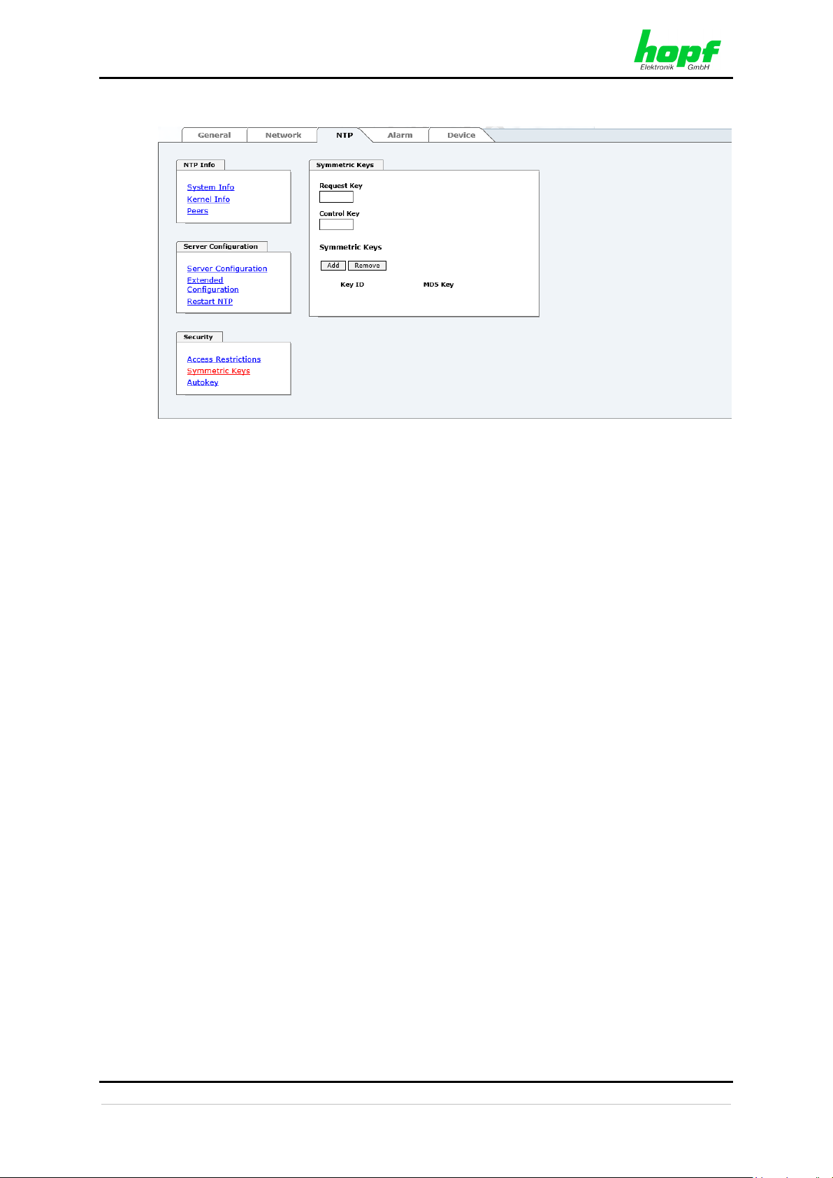
HTTP/HTTPS WEBGUI – WEB BROWSER CONFIGURATION INTERFACE
7273 and 7273RC NTP/SINEC H1 LAN Board - V08.00 79 / 113
hopf
Elektronik GmbH
Nottebohmstr. 41 • D-58511 Lüdenscheid • Tel.: +49 (0)2351 9386-86 • Fax: +49 (0)2351 9386-93 • Internet: http://www.hopf.com • E-Mail: info@hopf.com
6.3.3.8 Symmetric Key and Autokey
6.3.3.8.1 Why Authentication?
Most NTP users do not require authentication as the protocol contains several filters (for bad
time).
Despite this, however, the use of authentication is common.
There are certain reasons for this:
• Time should only be used from safe sources
• An attacker broadcasts false time signals
• An attacker poses as another time server

HTTP/HTTPS WEBGUI – WEB BROWSER CONFIGURATION INTERFACE
80 / 113 7273 and 7273RC NTP/SINEC H1 LAN Board - V08.00
hopf
Elektronik GmbH
Nottebohmstr. 41 • D-58511 Lüdenscheid • Tel.: +49 (0)2351 9386-86 • Fax: +49 (0)2351 9386-93 • Internet: http://www.hopf.com • E-Mail: info@hopf.com
6.3.3.8.2 How is Authentication used in the NTP Service?
Client and server can execute an authentication whereby a code word is used on the client
side and a restriction on the server side.
NTP uses keys to implement the authentication. These keys are used when data is exchanged
between two machines.
In principle both sides must know this key. The key can generally be found in the
“*.*/etc/ntp.keys“ directory. It is unencrypted and hidden from public view. This means that the
key has to be distributed on a safe route to all communication partners. The key can be
downloaded for distribution under “Downloads” on the DEVICE tab. It is necessary to be
logged in as “Master” in order to access this.
The keyword key of a client’s ntp.conf determines the key that is used to communicate with
the designated server (e.g. the NTP LAN board). The key must be reliable if time is to be
synchronised. Authentication causes a delay. This delay is automatically taken into account
and adjusted in the current versions.
6.3.3.8.3 How is a key created?
A key is a sequence of up to 31 ASCII characters. Some characters with special significance
cannot be used (alphanumeric characters and the following symbols can be used:
. , ! " $ % & / { } [ ] ( ) = ? \ + - @ * ~ # ' < > | ; : _
A new line can be inserted by pressing the ADD key. The key which is stored in the key file
is entered on this line. The key ID is used to identify the key and is in the range from 1 – 65534.
This means that 65534 different keys can be defined.
Duplicate key ID’s are not allowed. Having now explained the principles of keys, it should be
possible to use a key in practically the same way as a password.
The value of the request key field is used as the password for the ntpdc tool while the value of
the control key field is used as the password for the ntpq tool.
More information is available at http://www.ntp.org/.
6.3.3.8.4 How does authentication work?
Basic authentication is a digital signature and not data encryption (if there is any difference
between the two). The data packet and the key are used to create a non-reversible number
which is attached to the packet.
The receiver (which has the same key) carries out the same calculation and compares the
results. Authentication has been successful if the results concur.

HTTP/HTTPS WEBGUI – WEB BROWSER CONFIGURATION INTERFACE
7273 and 7273RC NTP/SINEC H1 LAN Board - V08.00 81 / 113
hopf
Elektronik GmbH
Nottebohmstr. 41 • D-58511 Lüdenscheid • Tel.: +49 (0)2351 9386-86 • Fax: +49 (0)2351 9386-93 • Internet: http://www.hopf.com • E-Mail: info@hopf.com
6.3.3.9 Autokey / Public Key Cryptography
NTPv4 offers a new Autokey scheme based on public key cryptography.
As a basic principle, public key cryptography is safer than symmetric key cryptography,
as protection is based on a private value which is generated by each host and is never visible.
In order to enable Autokey v2 authentication, the “Autokey Enabled” option must be set to
"enabled" and a password specified (may not be blank).
A new server key and certificate can be generated by pressing the "Generate now" button.
Generate now
This should be carried out regularly as these keys are only valid for one
year.
If the NTS board is to form part of an NTP trust group, a group key can be defined and
uploaded with the "Upload now" button.
Detailed information about the NTP Autokey scheme can be found in the NTP documentation
(http://www.ntp.org/).
Changes in data do not take effect immediately after clicking on the “Apply”
symbol. The NTP service MUST also be restarted (see Chapter 6.3.3.6
Restart NTP).

HTTP/HTTPS WEBGUI – WEB BROWSER CONFIGURATION INTERFACE
82 / 113 7273 and 7273RC NTP/SINEC H1 LAN Board - V08.00
hopf
Elektronik GmbH
Nottebohmstr. 41 • D-58511 Lüdenscheid • Tel.: +49 (0)2351 9386-86 • Fax: +49 (0)2351 9386-93 • Internet: http://www.hopf.com • E-Mail: info@hopf.com
6.3.4 ALARM Tab
All the links within the tabs on the left hand side lead to corresponding detailed setting options.
6.3.4.1 Syslog Configuration
It is necessary to enter the name or IPv4 or IPv6 address of a Syslog server in order to store
every configured alarm situation which occurs on the Board in a Linux/Unix Syslog. If
everything is configured correctly and enabled (dependent on the Syslog level), every
message is transmitted to the Syslog server and stored in the Syslog file there.
Syslog uses Port 514.
Co-logging on the Board itself is not possible as the internal memory is not of sufficient size.
It should be noted that the standard Linux/Unix Syslog mechanism is used for this functionality.
This is not the same as the Windows System Event mechanism!
The alarm level designates the priority level of the messages to be transmitted and the level
from which transmission is to take place (see Chapter 6.3.4.4 Alarm ).
Alarm Level
Transmitted Messages
none
no messages
info
info / warning / error / alarm
warning
warning / error / alarm
error
error / alarm
alarm
alarm
The NTP service implemented on this Board can transmit its own Syslog messages
(see Chapter 6.3.3.4.2 General / Log NTP Messages to Syslog).
Generated Syslog messages of board 7273(RC) are described in Chapter 10.5 Syslog
Messages.

HTTP/HTTPS WEBGUI – WEB BROWSER CONFIGURATION INTERFACE
7273 and 7273RC NTP/SINEC H1 LAN Board - V08.00 83 / 113
hopf
Elektronik GmbH
Nottebohmstr. 41 • D-58511 Lüdenscheid • Tel.: +49 (0)2351 9386-86 • Fax: +49 (0)2351 9386-93 • Internet: http://www.hopf.com • E-Mail: info@hopf.com
6.3.4.2 E-mail Configuration
E-mail notification is one of the important features of this device which offer technical
personnel the opportunity to monitor and/or control the IT environment.
It is possible to configure various, independent E-mail addresses which each have different
alarm levels.
Dependent on the configured level, an E-mail is sent after an error has occurred on the
respective receiver.
A valid E-mail server (SMTP server) must be entered for the purpose of correct configuration.
Some E-mail servers only accept messages if the sender address entered is valid (spam
protection). This can be inserted in the “Sender Address” field.
The Alarm Level designates the priority level of the messages to be sent and the level from
which they are to be sent (see Chapter 6.3.4.4 Alarm ).
Alarm Level
Transmitted Messages
none
no messages
info
info / warning / error / alarm
warning
warning / error / alarm
error
error / alarm
alarm
alarm
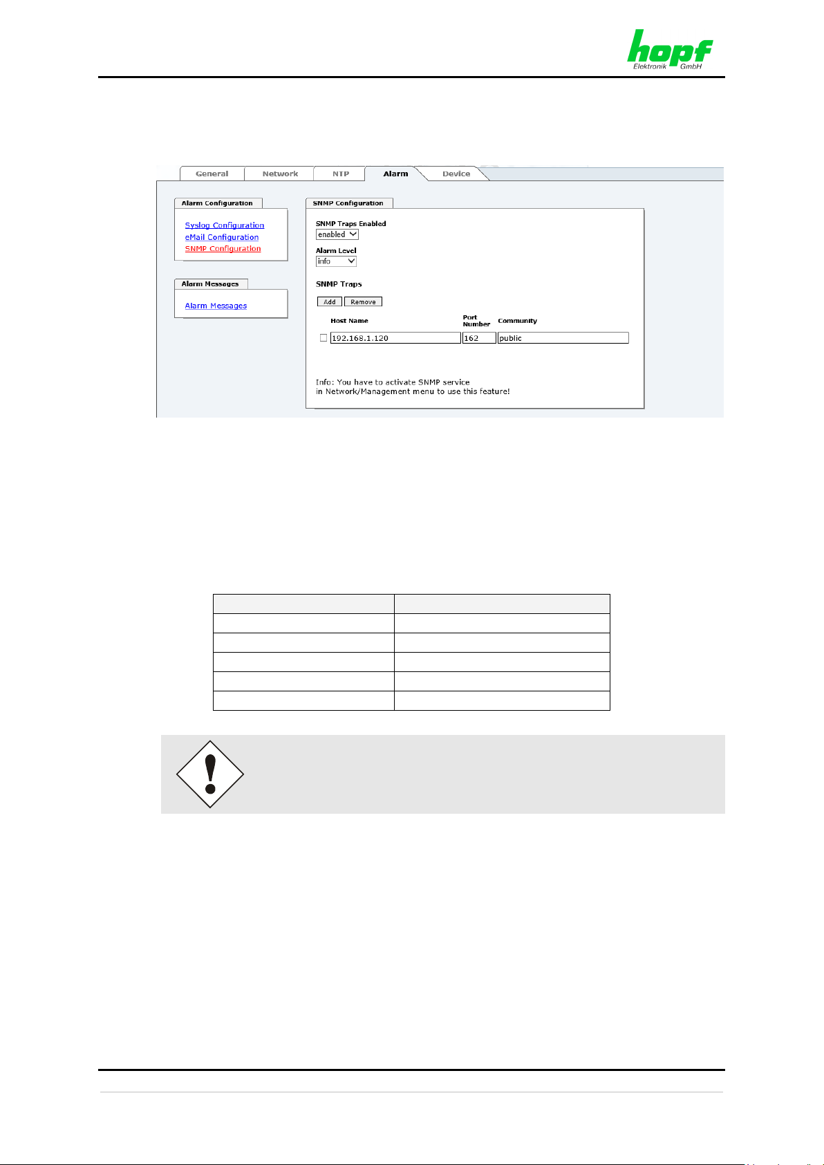
HTTP/HTTPS WEBGUI – WEB BROWSER CONFIGURATION INTERFACE
84 / 113 7273 and 7273RC NTP/SINEC H1 LAN Board - V08.00
hopf
Elektronik GmbH
Nottebohmstr. 41 • D-58511 Lüdenscheid • Tel.: +49 (0)2351 9386-86 • Fax: +49 (0)2351 9386-93 • Internet: http://www.hopf.com • E-Mail: info@hopf.com
6.3.4.3 SNMP Configuration / TRAP Configuration
It is possible to use an SNMP agent (with MIB) or to configure SNMP traps in order to monitor
the Board over SNMP.
SNMP traps are sent to the configured hosts over the network. It should be noted that these
are based on UDP and therefore it is not certain that they will reach the configured host!
Several hosts can be configured. However, all have the same alarm level.
The private
hopf
enterprise MIB is also available over the web (see Chapter 6.3.5.12
Downloading Configurations / SNMP MIB).
The “Alarm Level” designates the priority level of the messages to be sent and the level from
which they are to be sent (see Chapter 6.3.4.4 Alarm ).
Alarm Level
Transmitted Messages
none
no messages
info
info / warning / error / alarm
warning
warning / error / alarm
error
error / alarm
alarm
alarm
SNMP protocol must be enabled in order to use SNMP (see Chapter
6.3.2.5 Management-Protocols – HTTP, SNMP etc.).

HTTP/HTTPS WEBGUI – WEB BROWSER CONFIGURATION INTERFACE
7273 and 7273RC NTP/SINEC H1 LAN Board - V08.00 85 / 113
hopf
Elektronik GmbH
Nottebohmstr. 41 • D-58511 Lüdenscheid • Tel.: +49 (0)2351 9386-86 • Fax: +49 (0)2351 9386-93 • Internet: http://www.hopf.com • E-Mail: info@hopf.com
6.3.4.4 Alarm Messages
Every message shown in the image can be configured with the displayed alarm levels. If level
NONE is selected this means that this message is completely ignored.
A corresponding action is carried out if an event occurs, depending on the messages, their
configured levels and the configured notification levels of the E-mails.
Modified settings are failsafe stored after Apply and Save only.

HTTP/HTTPS WEBGUI – WEB BROWSER CONFIGURATION INTERFACE
86 / 113 7273 and 7273RC NTP/SINEC H1 LAN Board - V08.00
hopf
Elektronik GmbH
Nottebohmstr. 41 • D-58511 Lüdenscheid • Tel.: +49 (0)2351 9386-86 • Fax: +49 (0)2351 9386-93 • Internet: http://www.hopf.com • E-Mail: info@hopf.com
6.3.5 DEVICE Tab
All the links within the tabs on the left hand side lead to corresponding detailed setting options.
This tab provides the basic information about the Board hardware and software/firmware.
Password administration and the update services for the Board are also made accessible via
this website. The complete download zone is also a component of this site.
6.3.5.1 Device Information
All information is available exclusively in write-protected and read-only form. Information about
the Board type, serial number and current software versions is provided to the user for service
and enquiry purposes.
6.3.5.2 Hardware Information
Read-only access is provided here in the same way as for device information.
The user requires this information in the case of service requests, e.g. MACH version,
hardware status etc.
The settings of the DIP-switch on the board 7273(RC) will be shown under the point "Current
DIP Switch Settings"

HTTP/HTTPS WEBGUI – WEB BROWSER CONFIGURATION INTERFACE
7273 and 7273RC NTP/SINEC H1 LAN Board - V08.00 87 / 113
hopf
Elektronik GmbH
Nottebohmstr. 41 • D-58511 Lüdenscheid • Tel.: +49 (0)2351 9386-86 • Fax: +49 (0)2351 9386-93 • Internet: http://www.hopf.com • E-Mail: info@hopf.com
6.3.5.3 Restoring the Factory Settings - Factory Defaults
In some cases it may be necessary or desirable to restore all of the Board’s settings to their
delivered condition (factory defaults).
This function serves to restore all values in the flash memory to their default values. This also
includes passwords (see Chapter 9 Factory Defaults of Board 7273(RC)).
Please log in as a “Master” user in accordance with the description in Chapter 6.2.1 LOGIN
and LOGOUT as a User
Press the "Reset now" button and wait until the restart has been completed.
Once this procedure has been triggered there is NO possibility of restoring the deleted
configuration.
After a factory default a complete check (and reconfiguration of the Board
where appropriate) is required. In particular, the default MASTER and
DEVICE passwords must be reset.

HTTP/HTTPS WEBGUI – WEB BROWSER CONFIGURATION INTERFACE
88 / 113 7273 and 7273RC NTP/SINEC H1 LAN Board - V08.00
hopf
Elektronik GmbH
Nottebohmstr. 41 • D-58511 Lüdenscheid • Tel.: +49 (0)2351 9386-86 • Fax: +49 (0)2351 9386-93 • Internet: http://www.hopf.com • E-Mail: info@hopf.com
6.3.5.4 Restarting the Board (Reboot Device / Hardware Reset)
The restart concerns Board 7273(RC) only.
Reboot Device: Restart of the internal Operating System
Hardware Reset: Board Reset including all Hardware components
All settings not saved with "Save" are lost on Reboot / Hardware Reset
(see Chapter 6.2.3 Entry or Changing Data).
In broad terms, the NTP service implemented on the Board is restarted. This leads to a
renewed alignment phase with the loss of the stability and accuracy reached up to this point.
Please log in as a “Master” user in accordance with the description in Chapter 6.2.1 LOGIN
and LOGOUT as a User.
Pressing the "Reset now" or "Perform Reset now" button releases a restart.

HTTP/HTTPS WEBGUI – WEB BROWSER CONFIGURATION INTERFACE
7273 and 7273RC NTP/SINEC H1 LAN Board - V08.00 89 / 113
hopf
Elektronik GmbH
Nottebohmstr. 41 • D-58511 Lüdenscheid • Tel.: +49 (0)2351 9386-86 • Fax: +49 (0)2351 9386-93 • Internet: http://www.hopf.com • E-Mail: info@hopf.com
6.3.5.5 Image Update & H8 Firmware Update
Patches and error recovery are provided for the individual Boards by means of updates.
Both the embedded image and the H8 firmware can only be downloaded to the Board via the
web interface (login as “Master” user required). See also Chapter 2.4 Firmware Update.
The following points should be noted regarding updates:
• Only experienced users or trained technical personnel should carry
out an update after checking all necessary preconditions.
• Important: Faulty updates or update attempts may under certain
circumstances require the Board to be returned to the factory for
rectification at the owner’s expense.
• Check that the update on hand is suitable for your Board. If in doubt
please consult the support of the
hopf
company.
• In order to guarantee a correct update, the "New version of saved
site" function must be set to "On each access to the site" in the
Internet browser used.
• During the update procedure, the device must not be switched off
and settings must not be saved to the flash memory!
• Updates are always executed as software set. I.e. H8 firmware
update + image update. Unless specifically defined otherwise in the
SET, it is absolutely essential to complete the H8 firmware update
first, followed by the image update.
• For the Update please pay attention to the points in Chapter 2.4
Firmware Update.
In order to carry out an update, enter the name and the folder in which the update / firmware
image is located in the text field or open the file selection dialogue by pressing the "Browse"
button.
Correct firmware and image designations are (e.g.):
8029_7273_128_v0201.mot
for the H8 firmware (update takes approx. 1-1.5 minutes)
upgrade_8029-SERI_gen_rel_v0700.img
or upgrade_8029-NAND_gen_rel_v0700.img
for the embedded image (update takes approx. 2-3 minutes)

HTTP/HTTPS WEBGUI – WEB BROWSER CONFIGURATION INTERFACE
90 / 113 7273 and 7273RC NTP/SINEC H1 LAN Board - V08.00
hopf
Elektronik GmbH
Nottebohmstr. 41 • D-58511 Lüdenscheid • Tel.: +49 (0)2351 9386-86 • Fax: +49 (0)2351 9386-93 • Internet: http://www.hopf.com • E-Mail: info@hopf.com
6.3.5.5.1 Select Image Update
ATTENTION
Important note for the identification of the required image update!
In order to select the correct image update, the digit marked red of the
serial number must be checked!
Required ZIP archive for the Image Update:
Red marked digit = 1
Red marked digit = 4
hopf7273_SET_v05xx.zip
hopf7273-NAND_SET-v08xx.zip
Content of the ZIP archive
• 8029_7273_v02xx_128.mot
• readme_7273.txt
• release-notes_7273.html
• upgrade_8029gen_rel_v05xx.img
Content of the ZIP archive
• 8029_7273_128_v02xx.mot
• readme_7273-NAND.txt
• release-notes_7273-NAND.html
• upgrade_8029-NAND_gen_rel_v07xx.img

HTTP/HTTPS WEBGUI – WEB BROWSER CONFIGURATION INTERFACE
7273 and 7273RC NTP/SINEC H1 LAN Board - V08.00 91 / 113
hopf
Elektronik GmbH
Nottebohmstr. 41 • D-58511 Lüdenscheid • Tel.: +49 (0)2351 9386-86 • Fax: +49 (0)2351 9386-93 • Internet: http://www.hopf.com • E-Mail: info@hopf.com
6.3.5.5.2 Start Image Update
The update process is started by pressing the "Update now" button. The update is installed if
the transfer and checksum test are successful. A success page is displayed and shows the
number of bytes that have been transferred and installed.
A restart of the Board with the new Firmware is done automatically after the H8-Firmware
update.
The procedure for the Image update differs only in how the Board is restarted.
After the image-update the WebGUI displays a window to confirm the restart (reboot) of the
board.

HTTP/HTTPS WEBGUI – WEB BROWSER CONFIGURATION INTERFACE
92 / 113 7273 and 7273RC NTP/SINEC H1 LAN Board - V08.00
hopf
Elektronik GmbH
Nottebohmstr. 41 • D-58511 Lüdenscheid • Tel.: +49 (0)2351 9386-86 • Fax: +49 (0)2351 9386-93 • Internet: http://www.hopf.com • E-Mail: info@hopf.com
6.3.5.6 Upload SSL-Server-Certificate
This offers the possibility to encrypt the https connections to the board 7273 (RC) with a userprovided SSL server certificate.
6.3.5.7 Customized Security Banner
Special security information which are displayed in the General-Tab can be entered here by
the user.
The security information can be written as 'unformatted' text. There are 2000 characters
available to write failsafe into the device.
When saving the text, only the following characters are accepted (all other characters are
discarded and therefore not displayed on the General page!):
• Capital letters (A…Z)
• Lowercase letters (a…z)
• Numbers (0…9)
• The following special characters: space (" "), exclamation mark ("!"), Comma (","), dot
("."), Colon (":"), question mark ("?")
•
After a successful storage the "Customized Security Banner" with the saved security
information is displayed in the General-Tab.
To delete the "Customized Security Banner" the inserted text must be deleted and saved
again.

HTTP/HTTPS WEBGUI – WEB BROWSER CONFIGURATION INTERFACE
7273 and 7273RC NTP/SINEC H1 LAN Board - V08.00 93 / 113
hopf
Elektronik GmbH
Nottebohmstr. 41 • D-58511 Lüdenscheid • Tel.: +49 (0)2351 9386-86 • Fax: +49 (0)2351 9386-93 • Internet: http://www.hopf.com • E-Mail: info@hopf.com
6.3.5.8 Option FG7273/PPM: Minute Pulse Length (PPM)
With this option FG7273/PPM a high active isolated minute pulse (high active) of +12V DC is
distributed on the 3-pole screw terminal. Further technical data can be found in Chapter 8
Technical Data.
The output is an "open collector" with a current limiter. For further information see Chapter
1.3.1.7 Option: Active 12V DC PPM (Minute Pulse).
This minute pulse is fully compatible to the minute pulse of the
hopf
board
7270/7271 (the electrical properties as well as the adjustable parameters).
The menu item Minute Pulse (PPM) is only indicated in WebGUI if this
function is also available for the board.
Both boards 7273 and 7273RC are available with the option FG7273/PPM.
A subsequent upgrading of this option is not possible by the customer.
The length of the pulse can be adjusted in 4 steps.
Pulse Length of the Minute Pulse (high active)
10 msec
100 msec
500 msec
1000 msec

HTTP/HTTPS WEBGUI – WEB BROWSER CONFIGURATION INTERFACE
94 / 113 7273 and 7273RC NTP/SINEC H1 LAN Board - V08.00
hopf
Elektronik GmbH
Nottebohmstr. 41 • D-58511 Lüdenscheid • Tel.: +49 (0)2351 9386-86 • Fax: +49 (0)2351 9386-93 • Internet: http://www.hopf.com • E-Mail: info@hopf.com
6.3.5.9 Product Activation
Optional features (e.g. IEEE 802.1Q Tagged VLAN) can be activated using a special activation
key which can be requested from
hopf
Elektronik GmbH.
An activation key is bound to a specific board and cannot be shared between different boards.
Overview
List of all options with its current activation status and the stored activation key.
Activate Feature
Input field to enter a new activation key. The activation key has 26 characters and can be
entered case insensitive. After entering a key the feature can be activated by pressing the
Apply button. If activation was successful the new feature is listed in the overview with status
“Active” and can be used immediately.
Key Reset
Clears all Activation Keys and sets all optional features to status “Inactive”. No optional feature
is available anymore after performing the Key Reset. If the feature is enabled again, the last
configuration for the optional feature is restored.

HTTP/HTTPS WEBGUI – WEB BROWSER CONFIGURATION INTERFACE
7273 and 7273RC NTP/SINEC H1 LAN Board - V08.00 95 / 113
hopf
Elektronik GmbH
Nottebohmstr. 41 • D-58511 Lüdenscheid • Tel.: +49 (0)2351 9386-86 • Fax: +49 (0)2351 9386-93 • Internet: http://www.hopf.com • E-Mail: info@hopf.com
6.3.5.10 Diagnostics Function
It "status messages" is activated the output is processed as SYSLOG message. This function
should only be used/activated in case a problem arises and after consulting the
hopf
support.
6.3.5.11 Passwords (Master/Device)
Differentiation is made between upper and lower case characters in passwords. In principle,
all alphanumeric characters and the following symbols are allowed in passwords:
. , ! " $ % & / { } [ ] ( ) = ? \ + - @ * ~ # ' < > | ; : _
(See also Chapter 6.2.1 LOGIN and LOGOUT as a User)
A new password must contain at least one capital letter and lowercase
letter, a number, and six characters.

HTTP/HTTPS WEBGUI – WEB BROWSER CONFIGURATION INTERFACE
96 / 113 7273 and 7273RC NTP/SINEC H1 LAN Board - V08.00
hopf
Elektronik GmbH
Nottebohmstr. 41 • D-58511 Lüdenscheid • Tel.: +49 (0)2351 9386-86 • Fax: +49 (0)2351 9386-93 • Internet: http://www.hopf.com • E-Mail: info@hopf.com
6.3.5.12 Downloading Configurations / SNMP MIB
In order to be able to download certain configuration files via the web interface it is necessary
to be logged on as a "master" user.
The loaded file System Configuration from the board is only used for
support purposes and cannot be reloaded for adjusting the settings.
Before a file System Configuration download it is imperative to press the
button Refresh System Configuration .
The "private
hopf
enterprise MIB" is also available via the WebGUI in this area.

SSH AND TELNET BASIC CONFIGURATION
7273 and 7273RC NTP/SINEC H1 LAN Board - V08.00 97 / 113
hopf
Elektronik GmbH
Nottebohmstr. 41 • D-58511 Lüdenscheid • Tel.: +49 (0)2351 9386-86 • Fax: +49 (0)2351 9386-93 • Internet: http://www.hopf.com • E-Mail: info@hopf.com
7 SSH and Telnet Basic Configuration
Only basic configuration is possible via SSH or Telnet. The complete
configuration of Board 7273(RC) takes place exclusively via the WebGUI.
It is just as easy to use SSH (Port 22) or Telnet (Port 23) as the WebGUI. Both protocols use
the same user interface and menu structure.
The user names and passwords are the same as on the WebGUI and are kept in alignment
(see Chapter 6.3.5.11 Passwords (Master/Device)).
SSH does not allow blank passwords for safety reasons.
The corresponding service is to be enabled for the use of Telnet or SSH
(see Chapter 6.3.2.5 Management-Protocols – HTTP, SNMP etc.)
Navigation through the menu takes place by entering the respective number associated with
the menu option (as can be seen in the above image).

TECHNICAL DATA
98 / 113 7273 and 7273RC NTP/SINEC H1 LAN Board - V08.00
hopf
Elektronik GmbH
Nottebohmstr. 41 • D-58511 Lüdenscheid • Tel.: +49 (0)2351 9386-86 • Fax: +49 (0)2351 9386-93 • Internet: http://www.hopf.com • E-Mail: info@hopf.com
8 Technical Data
General technical Data of the Board 7273(RC).
Assembly
Model
Euro-board 160 x 100 mm
Power supply
internal system voltage Vpp
5V DC 5% via system bus
Environmental Conditions
Temperature range:
operation:
0°C to +40°C
storage:
-20°C to +75°C
Humidity:
max. 95%, not condensed
GPS System - Accuracy
Lambda < 15ms
Stability < 0.2ppm
HIGH
Lambda < 15ms
Stability >= 0.2ppm und <= 2ppm, Offset < 1ms
HIGH
Lambda < 15ms
Stability > 2ppm oder Offset >= 1ms
MEDIUM
DCF77 System - Accuracy
Lambda < 15ms
Stability < 0.6ppm
HIGH
Lambda < 15ms
Stability >= 0.6ppm und <= 2ppm, Offset < 2ms
HIGH
Lambda < 15ms
Stability > 2ppm oder Offset >= 2ms
MEDIUM
Time Protocols
• NTPv4 Server
• NTP Broadcast Mode
• NTP Multicast Mode
• NTP Client for additional NTP Servers (Redundancy)
• SNTP Server
• NTP Symmetric Key Encryption
• NTP Autokey Encryption
• NTP Access Restrictions
• PPS Time Source
• RFC-867 DAYTIME Server
• RFC-868 TIME Server
• SINEC H1 time datagram
TCP/IP Network Protocols
• HTTP/ HTTPS
• FTP
• Telnet
• SSH
• SNMPv2 / SNMPv3
• NTP (including SNTP)
• SINEC H1 time datagram
Configuration
• HTTP/HTTPS-WebGUI (Browser Based)
• Telnet
• SSH
•
hopf
Base System via keypad and display resp.
hmc
remote access
•
hmc
network configuration assistant

TECHNICAL DATA
7273 and 7273RC NTP/SINEC H1 LAN Board - V08.00 99 / 113
hopf
Elektronik GmbH
Nottebohmstr. 41 • D-58511 Lüdenscheid • Tel.: +49 (0)2351 9386-86 • Fax: +49 (0)2351 9386-93 • Internet: http://www.hopf.com • E-Mail: info@hopf.com
Power consumption
Normal operation
Typical: 230 mA (max. 300 mA)
Boot phase
Typical: 230 mA (max. 300 mA)
LAN
Network Connection
Via a LAN cable with RJ45 plug (recommended cable type
CAT5 or better).
Requests per second
max. 1000 requests
Number of connectable clients
Theoretically unlimited
Network interface ETH0
10/100 Base-T
Ethernet compatibility
Version 2.0 / IEEE 802.3
Isolation voltage
(network to system side)
1500 Vrms
MTBF
MTBF
> 900,000 hours
CE Conformity
EMV Directive 2014/30/EU
EN 55022 : 2010 / AC : 2011
EN 61000-3-2 : 2006 / A2 : 2009, EN 61000-3-3 : 2013
EN 55024 : 2010
Low Voltage Directive 2014/35/EU
EN 60950-1 : 2006 / AC : 2011
Board 7273 with Option FG7273/PPM (Output Minute Pulse)
Minute Pulse
12V DC, potential isolated
via an 'open collector unit'
As Current Source
typical: 20mA (max. 30 mA)
The output load should be (RL < 600 Ohm), because of a too
small edge steepness.
Output logic
high active
Active output voltage
12V DC, max. 100mA, potential isolated
Isolation voltage
min. 1000V DC

FACTORY DEFAULTS OF BOARD 7273(RC)
100 / 113 7273 and 7273RC NTP/SINEC H1 LAN Board - V08.00
hopf
Elektronik GmbH
Nottebohmstr. 41 • D-58511 Lüdenscheid • Tel.: +49 (0)2351 9386-86 • Fax: +49 (0)2351 9386-93 • Internet: http://www.hopf.com • E-Mail: info@hopf.com
9 Factory Defaults of Board 7273(RC)
The default delivery status of the Board 7273(RC) meets the factory default values when using
GPS synchronization sources. In case of DCF77 synchronization (different product variant)
the function "NTP / General / Sync Source" is factrory-set to "DCF77" on delivery.
Using the board in DCF77 systems (different product variant) the setting
for NTP / General / Sync Source" needs to be re-configured to "DCF77"
after a factory default.
NTP Server Configuration
Setting
WebGUI
Sync. Source
DCF77
DCF77
9.1 Network
Host/Name Service
Setting
WebGUI Presentation
Hostname
hopf7273
hopf7273
Use Manual DNS Entries
Enabled
Enabled
DNS Server 1 IPv4/IPv6 Address
Blank
---
DNS Server 2 IPv4/IPv6 Address
Blank
---
DNS Server 3 IPv4/IPv6 Address
Blank
---
Use Manual Gateway Entries
Enabled
Enabled
Default Gateway IPv4 Address
Blank
---
Default Gateway IPv6 Address
Blank
---
Network Interface ETH0
Setting
WebGUI
Use Custom Hardware Address (MAC)
Disabled
disabled
Custom Hardware Address (MAC)
Blank
---
DHCP
Enabled
enabled
IPv4 Address
192.168.0.1
192.168.0.1
IPv4 Netmask
255.255.255.0
255.255.255.0
Operation mode
Auto negotiate
Auto negotiate
VLAN Interfaces
Disabled
Disabled
IPv6 Settings
Disabled
Disabled
Routing
Setting
WebGUI
Use Route File
Disabled
Disabled
User Defined Routes
Blank
---
Management
Setting
WebGUI
HTTP
Enabled
Enabled
HTTPS
Disabled
Disabled
SSH
Enabled
Enabled
TELNET
Disabled
Disabled
SNMP
Disabled
Disabled
System Location
Blank
---
System Contact
Blank
---
Read Only Community
Blank
---
Read/Write Community
Blank
---
Security Name
Blank
---
Access Rights
Readonly
Readonly
Authentication Protocol
MD5
MD5
Authentication Passphrase
Blank
---
Privacy Protocol
DES
DES
Privacy Passphrase
Blank
---
Read/Write Community
Blank
---
Time Protocols
Setting
WebGUI
NTP
Enabled
enabled
DAYTIME
Disabled
disabled
TIME
Disabled
disabled
SINEC H1 time datagram
Disabled
disabled
 Loading...