

Page 1

_____________________________________________________________
Technical Manual
GPS Sync Module
Model 8024GPS
ENGLISH
Version: 02.00 - 12.09.2018
_____________________________________________________________
Valid for Devices 8024GPS with FIRMWARE
Version: 02.xx
and from
hmc
software
Version: 01.13
Industriefunkuhren
Page 2

2 / 76 8024GPS - GPS Sync Module - V02.00
hopf
Elektronik GmbH
Nottebohmstr. 41 • D-58511 Lüdenscheid • Tel.: +49 (0)2351 9386-86 • Fax: +49 (0)2351 9386-93 • Internet: http://www.hopf.com • E-Mail: [email protected]
Page 3

INPORTANT NOTES
8024GPS - GPS Sync Module - V02.00 3 / 76
hopf
Elektronik GmbH
Nottebohmstr. 41 • D-58511 Lüdenscheid • Tel.: +49 (0)2351 9386-86 • Fax: +49 (0)2351 9386-93 • Internet: http://www.hopf.com • E-Mail: [email protected]
Version number (Firmware / Manual)
THE FIRST TWO DIGITS OF THE VERSION NUMBER OF THE TECHNICAL MANUAL AND
THE FIRST TWO DIGITS OF THE FIRMWARE VERSION MUST COMPLY WITH EACH OTHER.
THEY INDICATE THE FUNCTIONAL CORRELATION BETWEEN DEVICE AND TECHNICAL
MANUAL.
THE DIGITS AFTER THE POINT IN THE VERSION NUMBER INDICATE CORRECTIONS IN THE
FIRMWARE / MANUAL THAT ARE OF NO SIGNIFICANCE FOR THE FUNCTION.
Downloading Technical Manuals
All current manuals of our products are available free of charge via our homepage on the
Internet.
Symbols and Characters
Operational Reliability
Disregard may cause damages to persons or material.
Functionality
Disregard may impact function of system/device.
Information
Notes and Information.
Page 4

SERVICE RELIABILITY
4 / 76 8024GPS - GPS Sync Module - V02.00
hopf
Elektronik GmbH
Nottebohmstr. 41 • D-58511 Lüdenscheid • Tel.: +49 (0)2351 9386-86 • Fax: +49 (0)2351 9386-93 • Internet: http://www.hopf.com • E-Mail: [email protected]
Safety regulations
The safety regulations and observance of the technical data serve to
ensure trouble-free operation of the device and protection of persons and
material. It is therefore of utmost importance to observe and compliance
with these regulations.
If these are not complied with, then no claims may be made under the
terms of the warranty. No liability will be assumed for any ensuing
damage.
Safety of the device
This device has been manufactured in accordance with the latest
technological standards and approved safety regulations
The device should only be put into operation by trained and qualified staff.
Care must be taken that all cable connections are laid and fixed in position
correctly. The device should only be operated with the voltage supply
indicated on the identification label.
The device should only be operated by qualified staff or employees who
have received specific instruction.
If a device must be opened for repair, this should only be carried out by
employees with appropriate qualifications or by
hopf
Elektronik GmbH.
Before a device is opened or a fuse is changed all power supplies must
be disconnected.
If there are reasons to believe that the operational safety can no longer
be guaranteed the device must be taken out of service and labelled
accordingly.
The safety may be impaired when the device does not operate properly
or if it is obviously damaged.
CE-Conformity
This device fulfils the requirements of the EU directive 2014/30/EU
"Electromagnetic Compatibility" and 2014/35/EU "Low Voltage Equipment".
Therefore the device bears the CE identification marking
(CE = Communautés Européennes = European communities)
The CE indicates to the controlling bodies that the product complies with the
requirements of the EU directive - especially with regard to protection of health and safety for
the operator and the user - and may be released for sale within the common markets.
Page 5

TABLE OF CONTENTS
8024GPS - GPS Sync Module - V02.00 5 / 76
hopf
Elektronik GmbH
Nottebohmstr. 41 • D-58511 Lüdenscheid • Tel.: +49 (0)2351 9386-86 • Fax: +49 (0)2351 9386-93 • Internet: http://www.hopf.com • E-Mail: [email protected]
Contents Page
1 General .......................................................................................................................... 7
2 Hardware ....................................................................................................................... 8
2.1 Example: Front Panel for DIN Rail Mounting .............................................................................8
2.2 Front Panel Connections ............................................................................................................8
2.2.1 GPS Antenna Connection .....................................................................................................8
2.2.2 Status LEDs ..........................................................................................................................9
2.2.3 Status Optical Coupler ..........................................................................................................9
2.2.4 Serial-Remote Interface for
hmc
software ...........................................................................9
2.3 Back-up Clock ............................................................................................................................9
2.4 Voltage Feed ..............................................................................................................................9
2.5 Further Signal Outputs ...............................................................................................................9
3
hmc (hopf
Management Console) software ........................................................... 10
3.1 Installation on Microsoft Windows ........................................................................................... 10
3.2 Starting the
hopf
Management Console software ................................................................ 11
3.3 The Control Elements ............................................................................................................. 11
3.3.1 The Menu - Area A ............................................................................................................. 12
3.3.2 The Tool Bar - Area B ........................................................................................................ 13
3.3.3 The Device Tree - Area C .................................................................................................. 13
3.3.4 The Main Area - Area D ..................................................................................................... 14
3.3.5 The Status Bar - Area E ..................................................................................................... 14
3.4 Create a serial-remote Connection to
hmc
software ............................................................. 15
3.5 Operation / Display .................................................................................................................. 17
3.5.1 Configuration / Plausibility Check ...................................................................................... 18
3.5.2 Transmit Value Changes ................................................................................................... 18
3.5.3 Read from Device .............................................................................................................. 18
3.5.4 Undo All Changes .............................................................................................................. 19
3.5.5 Load a Configuration File ................................................................................................... 19
3.5.6 Save the Current Configuration ......................................................................................... 19
3.6 Description of the Tabs ........................................................................................................... 20
3.6.1 Time and date – Tab .......................................................................................................... 20
3.6.1.1 Time panel 21
3.6.1.2 Setting Date and Time 22
3.6.1.3 Daylight Saving panel 23
3.6.1.4 Time Zone Selection (Time Zone Offset) panel 24
3.6.2 System – Tab ..................................................................................................................... 26
3.6.2.1 SyncON / SyncOFF 26
3.6.2.2 Reset 27
3.6.3 GPS – Tab ......................................................................................................................... 28
3.6.4 Output – Tab ...................................................................................................................... 29
3.6.4.1 PPS - optional hardware necessary 30
3.6.4.1.1 PPS duration 30
3.6.4.1.2 Minimum Sync.-Status - Status-Dependent Pulse Output 30
3.6.4.1.3 Status of the Signal Output 31
3.6.4.1.4 Output inverted – Polarity of the output Pulse 31
3.6.4.1.5 Special Configuration 31
3.6.4.2 DCF77 - optional hardware necessary 32
3.6.4.2.1 Time Base of the Transmitted DCF77 Pulse 32
Page 6

TABLE OF CONTENTS
6 / 76 8024GPS - GPS Sync Module - V02.00
hopf
Elektronik GmbH
Nottebohmstr. 41 • D-58511 Lüdenscheid • Tel.: +49 (0)2351 9386-86 • Fax: +49 (0)2351 9386-93 • Internet: http://www.hopf.com • E-Mail: [email protected]
3.6.4.2.2 Output if blocked - Signal Output in the event of a Fault 33
3.6.4.2.3 Minimum Sync.-Status - Status-Dependent Pulse Output 33
3.6.4.2.4 Status of the Signal Output 33
3.6.4.2.5 Output inverted – Polarity of the output DCF77 Pulse 34
3.6.4.2.6 Special Configuration 34
3.6.4.3 IRIG-B- optional hardware nesessary 35
3.6.4.3.1 Selection of the IRIG-B Format 35
3.6.4.3.2 Timebase – Timebase of the output IRIG-B Signal 36
3.6.4.3.3 Minimum Sync.-Status - Status-Dependent Pulse Output 36
3.6.4.3.4 Status of the Signal Output 36
3.6.4.3.5 Output inverted – Polarity of the output Pulse 37
3.6.4.3.6 Special Configuration 37
3.6.4.4 Cyclic Pulse - optional hardware nesessary 37
3.6.4.4.1 Cyclic Pulse every 37
3.6.4.4.2 Pulse duration 38
3.6.4.4.3 Time Base of the Transmitted Cyclic Pulse 38
3.6.4.4.1 Minimum Sync.-Status - Status-Dependent Pulse Output 38
3.6.4.4.2 Status of the Signal Output 39
3.6.4.4.3 Output inverted – Polarity of the output Pulse 39
3.6.4.4.4 Special Configuration 39
3.6.4.5 Serial Interface - optional hardware necessary 40
3.6.4.5.1 Serial Interface parameter 40
3.6.4.5.2 Timebase – Timebase of the output serial data string 41
3.6.4.5.3 Output scheme 41
3.6.4.5.4 Transmission Time 41
3.6.4.5.5 Special Configuration 42
3.6.4.5.6 String Output 42
3.6.4.6 Parameter Setting - optional hardware necessary 62
3.6.4.7 Status OC 63
3.6.5 Errors – Tab ....................................................................................................................... 64
3.6.6 Device – Tab ...................................................................................................................... 66
4 Fault Analysis / Troubleshooting ............................................................................... 67
4.1 Fault Scenarios ....................................................................................................................... 67
4.1.1 Complete Failure ................................................................................................................ 67
4.1.2 No GPS Reception / No Synchronization .......................................................................... 67
4.1.3 Incorrect Time Output ........................................................................................................ 69
4.1.4 No DST changeover........................................................................................................... 69
4.2 Support from the
hopf
Company ........................................................................................... 70
5 Maintenance / Care ..................................................................................................... 71
6 Technical Data ............................................................................................................ 72
7 Factory default ............................................................................................................ 74
8 Appendix ..................................................................................................................... 76
8.1 GPS (Global Positioning System) ........................................................................................... 76
Page 7

GENERAL
8024GPS - GPS Sync Module - V02.00 7 / 76
hopf
Elektronik GmbH
Nottebohmstr. 41 • D-58511 Lüdenscheid • Tel.: +49 (0)2351 9386-86 • Fax: +49 (0)2351 9386-93 • Internet: http://www.hopf.com • E-Mail: [email protected]
1 General
The
hopf
Sync Module 8024GPS is a GPS Module for the reception and evaluation of GPS
signals for high-precision signal generation and output of time information. In combination with
other hardware output modules, rack vesions and power supplies the module can be "customtailored" set-up and used for various applications. The configuration of the GPS settings and
the signal generation is made via the serial remote interface.
Some of the Sync Modules 8024GPS basic functions:
• Simple configuration using
hmc
software on remote interface
• Remote interface (Serial-Remote) on the front panel (RS232 format)
• Status LEDs on the front panel
• Status optical coupler on the front panel
• High freewheel accuracy through GPS-supported regulation of the internal quartz base
• Completely maintenance-free system
• SyncOFF timer (reception failure bypassing) for operation free of fault messages - even
in difficult reception conditions
• Redundant multiple validation of the synchronization signal for fault-free and leap-
free signal evaluation
• Maintenance-free, buffered back-up clock for more than three days
Accessories supplied:
• Serial programming cable KA6870 (2m, 9-pole socket to 9-pole socket) to connect
to a PC.
As the Module 8024GPS is supplied in system build-ups, the build-up of the unit and the
system-specific connections and signal outputs are documented in the accompanying manual.
Not all signal outputs parameterizable via the
hmc
software are always
available as physical outputs for the different system variants.
The available functions and their appropriate physical outputs are stated in
device-specific manual.
Page 8

HARDWARE
8 / 76 8024GPS - GPS Sync Module - V02.00
hopf
Elektronik GmbH
Nottebohmstr. 41 • D-58511 Lüdenscheid • Tel.: +49 (0)2351 9386-86 • Fax: +49 (0)2351 9386-93 • Internet: http://www.hopf.com • E-Mail: [email protected]
2 Hardware
This chapter describes the connections and LED elements of the Sync Module 8024GPS.
2.1 Example: Front Panel for DIN Rail Mounting
Status (LEDs + Optical Coupler)
3-pole Connector
Pin
Signal
1
Collector (+)
2
n.c.
3
Emitter (-)
LED
Meaning
RD
Status LED red
GN
Status LED green
GPS Antenna
BNC connector
GPS
Antenna Input
Serial-Remote
LED
Meaning
Rx
LED green - reception of serial data
Tx
Led yellow - transmission of serial data
9-pole SUB-D connector
Pin
Signal
1
n.c.
2
RS232c (V.24) RXD
3
RS232c (V.24) TXD
4
n.c.
5
GND 6 n.c.
7
n.c.
8
n.c.
9
n.c.
n.c. = not connected
2.2 Front Panel Connections
2.2.1 GPS Antenna Connection
The coaxial cable of the GPS antenna equipment is connected to the BNC socket marked
"GPS Antenna" on the front panel. Further specifications concerning the installation of the
antenna equipment, such as cable lengths and cable types, can be found in the document
titled "GPS Antenna Equipment".
Page 9

HARDWARE
8024GPS - GPS Sync Module - V02.00 9 / 76
hopf
Elektronik GmbH
Nottebohmstr. 41 • D-58511 Lüdenscheid • Tel.: +49 (0)2351 9386-86 • Fax: +49 (0)2351 9386-93 • Internet: http://www.hopf.com • E-Mail: [email protected]
2.2.2 Status LEDs
The status LEDs on the front panel signal the module's current (synchronization) status. The
meanings of the LEDs are as follows:
LED RD
- Red
LED GN
- Green
Status
STATUS
Code
Off
ON
Sync (radio-synchronous) with quartz regulation
SYNC
Off
Flashes
Sync (radio-synchronous) - SyncOFF timer running
SYOF
Flashes
ON
Sync (radio-synchronous) - simulation mode
SYSI
Flashes
Flashes
Quarz - SyncON timer running
QUON
ON
ON
Quarz - time was set via synchronization source
QUEX
ON
Flashes
Quarz - time set manually or after reset
QUSE
ON
Off
No valid time
INVA
Off
Off
No operating voltage / faulty
---
3Hz
Off
General Module Error (PCID)
INVA
3Hz
Invert
3Hz
User settings missing
(Difference time / ST-WT Changeover)
INVA
2.2.3 Status Optical Coupler
The status optical coupler provides a potential isolated switching contact for monitoring the
modules synchronization status.
Function:
Status output via 3-pole terminal with selection of the desired synchronisation status at which
reporting is to be activated:
Optical coupler:
• Selected status or better achieved – Optical coupler switched through
• Selected status not achieved – Optical coupler blocked
The desired reporting status is set via the
hmc
software.
2.2.4 Serial-Remote Interface for
hmc
software
The connection to a PC’s RS232 serial interface is made by means of the KA6870 interface
cable supplied.
The Serial-Remote interface for the configuration of the module is located on its front panel.
The transmission line (Tx) and reception line (Rx) have status LEDs which signal the activity
on the respective interface line.
No further configuration of this Serial-Remote interface is necessary.
2.3 Back-up Clock
The module has a maintenance-free, buffered backup clock for at least three days.
After a power failure the clock starts with the internal back-up clock information unless valid
time information was available beforehand.
2.4 Voltage Feed
The voltage feed takes place via the integrated power supply in the device.
2.5 Further Signal Outputs
Further available signal outputs of the respective system are stated in the accompanying
manual of the specific-device.
Page 10

HMC (HOPF MANAGEMENT CONSOLE) SOFTWARE
10 / 76 8024GPS - GPS Sync Module - V02.00
hopf
Elektronik GmbH
Nottebohmstr. 41 • D-58511 Lüdenscheid • Tel.: +49 (0)2351 9386-86 • Fax: +49 (0)2351 9386-93 • Internet: http://www.hopf.com • E-Mail: [email protected]
3
hmc (hopf
Management Console) software
This Chapter describes the operation and functionality of the
hopf
Management Console
(further abbreviated with
hmc
software) for the Sync Module 8024GPS.
3.1 Installation on Microsoft Windows
The installation routine is started via a double click on
HMC_v01.13_b1190_Windows_install.exe . A query for the installation routine's language will
appear - select English and click OK.
The installation wizard has been started now. In the lower area there are three buttons: Back,
Forward, Cancel. The Back button allows returning to previous steps at any time, in order to
see or change the settings there. If the settings in a step of the installation seem to be in order,
the button Forward will lead to the next step. The Cancel button allows leaving the installation
wizard at any time, in which case no installation of the
hmc
software will be performed on the
computer.
Step 1, The Welcome Screen
Information is shown, partly of a legal kind concerning the
licence conditions for the
hmc
software. Activating the Forward
button implies having read the information and accepting the
licence conditions.
Step 2, Installation Directory Selection
Instead of the standard installation directory, on a English
language Windows Installation this would be C:\Program
Files\Hopf, it is possible to install the
hmc
software into any
other directory. This allows the parallel installation of different
versions.
Step 3, Finalization
In this place, the user is informed that the next activation of the
Forward button will start the
hmc
software installation process,
following the settings made in the previous steps. In case of
concordance with these settings, the installation process is to
be commenced by activating the Forward button.
Step 4, The Installation Process
A progress bar indicates how much of the installation process
has been accomplished. It is necessary to wait until the
installation process is finished.
Cancel allows to cancel the process at any time. In this case, a
complete installation will not be performed.
Step 5, Confirmation
The user is informed that the
hmc
software has been
successfully installed. Activating Finish will close the installation
wizard. The
hmc
software has now been prepared for use and
may be started.
Page 11

HMC (HOPF MANAGEMENT CONSOLE) SOFTWARE
8024GPS - GPS Sync Module - V02.00 11 / 76
hopf
Elektronik GmbH
Nottebohmstr. 41 • D-58511 Lüdenscheid • Tel.: +49 (0)2351 9386-86 • Fax: +49 (0)2351 9386-93 • Internet: http://www.hopf.com • E-Mail: [email protected]
3.2 Starting the
hopf
Management Console software
In the Microsoft Windows Start Menu, under Programs and in the directory
hopf
, there is an
entry
hopf
Management Console. A simple click on this entry will start the
hmc
software.
Before the
hmc
software main window pops up, a splash
screen is shown. It contains a visualization of the
hmc
software start-up progress.
3.3 The Control Elements
• A - Menu: Access to all main features
• B - Tool Bar: Fast access to device management and help
• C - Device Tree: All integrated devices are visualized here
• D - Main Area: The welcome screen and the configuration area of connected devices
are shown here.
• E - Status Bar: Status information is shown here, to the right there are the language
selection and busy indicator.
Page 12

HMC (HOPF MANAGEMENT CONSOLE) SOFTWARE
12 / 76 8024GPS - GPS Sync Module - V02.00
hopf
Elektronik GmbH
Nottebohmstr. 41 • D-58511 Lüdenscheid • Tel.: +49 (0)2351 9386-86 • Fax: +49 (0)2351 9386-93 • Internet: http://www.hopf.com • E-Mail: [email protected]
3.3.1 The Menu - Area A
Submenu File
o Exit: Closes the
hmc
software. In case there are changes not yet transmitted, or
devices in a special state, a confirmation dialog is shown before closing.
Sub Menu Devices
o New: Integrate a new device. See Opening a device.
o Remove: Removes the selected device from the device tree. In case there are
changes not yet transmitted, or devices in a special state, a confirmation dialog is
shown before removal.
o Restore Connections: Restore all devices which have been connected after the last
program termination. After program start no device is connected automatically.
o Connect: Connect to the unconnected device selected in the device tree.
o Disconnect: Close the connection to the connected device selected in the device
tree. In case there are changes not yet transmitted, or devices in a special state, a
confirmation dialog is shown before disconnecting.
o Driver Management: Opens the driver management dialog, which shows details
about installed drivers and allows the addition of new drivers. See Driver
Management.
Sub Menu Tools
o View DCF77 Record: allows opening a DCF77 reception data record file from the file
system.
o Network configuration assistant: opens the Network Configuration Assistant. See
Network Configuration Assistant.
o NTP Analysis: opens the NTP Analysis dialog.
o View GPS Record: opens the GPS Record dialog.
o Verbose Logging: Enables/Disables verbose logging for detailed diagnosis. Should
be enabled only in error situations.
Sub Menu Help
o Info: Opens the Info Dialog, which shows the
hmc
software version number, as well
as contact information.
Page 13

HMC (HOPF MANAGEMENT CONSOLE) SOFTWARE
8024GPS - GPS Sync Module - V02.00 13 / 76
hopf
Elektronik GmbH
Nottebohmstr. 41 • D-58511 Lüdenscheid • Tel.: +49 (0)2351 9386-86 • Fax: +49 (0)2351 9386-93 • Internet: http://www.hopf.com • E-Mail: [email protected]
3.3.2 The Tool Bar - Area B
Integrate a new device
Like New in Menu Devices
Remove a device from the tree
Like Remove in Menu Devices
Reconnect devices
Like Reconnect Devices in Menu
Devices
Connect to a device
Like Connect in Menu Devices
Disconnect a device
Like Disconnect in Menu Devices
Show the info dialog
Like Info in Menu Devices
Show symbol explanations
3.3.3 The Device Tree - Area C
In the device tree, all devices are shown which are integrated in the
hmc
software. The
devices may be in connected or disconnected state. The difference is indicated by dictinct
icons and font weights.
Representation of a connected device
Representation of a disconnected device
All devices are visualized as sub elements of a main element representing the overview panel
and serving as a collective indicator showing the presence of not yet transmitted changes,
erroneous input and error statuses for connected devices.
Page 14

HMC (HOPF MANAGEMENT CONSOLE) SOFTWARE
14 / 76 8024GPS - GPS Sync Module - V02.00
hopf
Elektronik GmbH
Nottebohmstr. 41 • D-58511 Lüdenscheid • Tel.: +49 (0)2351 9386-86 • Fax: +49 (0)2351 9386-93 • Internet: http://www.hopf.com • E-Mail: [email protected]
3.3.4 The Main Area - Area D
In the main area, depending on the element selected in the device tree, either the welcome
panel, system overview or the selected device's configuration view is shown.
3.3.5 The Status Bar - Area E
At the left side of the status bar, warnings, error end activity messages are shown. At the right
side there is a language selector and a busy indicator showing that communication with a
device is taking place. Background communication like error status requests or communication
only suited to keep alive connections, is not indicated here.
When another than the active language is selected in the language selector, all shown texts
are exchanged to texts in the newly selected language. If a text is not available in the selected
language, the generally available English version of the text is shown.
In case there are changes not yet transmitted, or devices in a special state, a confirmation
dialog is shown before the language switch is performed.
Page 15

HMC (HOPF MANAGEMENT CONSOLE) SOFTWARE
8024GPS - GPS Sync Module - V02.00 15 / 76
hopf
Elektronik GmbH
Nottebohmstr. 41 • D-58511 Lüdenscheid • Tel.: +49 (0)2351 9386-86 • Fax: +49 (0)2351 9386-93 • Internet: http://www.hopf.com • E-Mail: [email protected]
3.4 Create a serial-remote Connection to
hmc
software
After the physical connection has been established via the serial programming cable KA6870
between the Serial-Remote interface of the Sync Module 8024GPS and a free serial interface
on the PC, the PC COM port used must be set up.
The menu item Devices / New and the Button in the tool bar both open the New Device
wizard:
First, the Communication Channel to the device 8024GPS to be opened has to be defined as
RS232. Forward confirms the selection.
Configuration of computer's serial port with serial parameters (9600-8-N-1, like shown in the
screenshot). Forward confirms the selection.
Page 16

HMC (HOPF MANAGEMENT CONSOLE) SOFTWARE
16 / 76 8024GPS - GPS Sync Module - V02.00
hopf
Elektronik GmbH
Nottebohmstr. 41 • D-58511 Lüdenscheid • Tel.: +49 (0)2351 9386-86 • Fax: +49 (0)2351 9386-93 • Internet: http://www.hopf.com • E-Mail: [email protected]
Probe connecting device 8024GPS. Forward confirms the selection.
Choice of using device driver. Finish confirms the selection and generate the remote
connection to the 8024GPS.
Page 17

HMC (HOPF MANAGEMENT CONSOLE) SOFTWARE
8024GPS - GPS Sync Module - V02.00 17 / 76
hopf
Elektronik GmbH
Nottebohmstr. 41 • D-58511 Lüdenscheid • Tel.: +49 (0)2351 9386-86 • Fax: +49 (0)2351 9386-93 • Internet: http://www.hopf.com • E-Mail: [email protected]
3.5 Operation / Display
When the connected device is selected in the device tree, the
hmc
software main area shows
the configuration view of the connected device.
The configuration view is divided into functional tabs. Click on one of these tabs to navigate
through the board. The selected tab is identified by a darker background colour, see the above
image (tab "Time and date" in this case).
On top and to the right in the configuration view, there is a tool bar for reading and setting
device properties, as well as for loading and saving complete configurations.
Transmit changes to the device.
Read all configuration properties from the device. Changes not yet
transmitted may be lost.
Undo all recent changes without re-reading from the device.
Load a complete configuration from a file.
Save the current configuration to a file.
Page 18

HMC (HOPF MANAGEMENT CONSOLE) SOFTWARE
18 / 76 8024GPS - GPS Sync Module - V02.00
hopf
Elektronik GmbH
Nottebohmstr. 41 • D-58511 Lüdenscheid • Tel.: +49 (0)2351 9386-86 • Fax: +49 (0)2351 9386-93 • Internet: http://www.hopf.com • E-Mail: [email protected]
3.5.1 Configuration / Plausibility Check
A reconfigured and not saved parameter is shown with a black changing-asterisk in the tab
and in the device tree.
In case of an invalid input, a red asterisk will be shown and the causing input control is
highlighted with pink background colour.
Transmitting values to a device is not possible whenever an invalid input is present.
3.5.2 Transmit Value Changes
Pushing the button , transmit changes to device, all present configuration value changes
that have not yet been successfully transmitted to the device are transmitted immediately. The
action is going to fail if there are any invalid inputs in any of the device's tabs. In that case, the
effort will result in an error dialog. Transmission will always affect all changes in all tabs.
3.5.3 Read from Device
The button , read all values from device, causes a complete re-read of all values from the
device, losing all eventually present changes that have not yet been transmitted.
Page 19

HMC (HOPF MANAGEMENT CONSOLE) SOFTWARE
8024GPS - GPS Sync Module - V02.00 19 / 76
hopf
Elektronik GmbH
Nottebohmstr. 41 • D-58511 Lüdenscheid • Tel.: +49 (0)2351 9386-86 • Fax: +49 (0)2351 9386-93 • Internet: http://www.hopf.com • E-Mail: [email protected]
3.5.4 Undo All Changes
Pushing the button , undo all changes, will discard all eventually present changes that have
not yet been transmitted without reading the new state from the device.
3.5.5 Load a Configuration File
Pushing the button , load a configuration file, starts a file-open-dialog for choosing a
configuration file to load into the device. This file must have been saved using the exact same
device driver, otherwise loading the configuration is going to fail showing an error dialog.
This file must have been saved using the exact same device driver.
3.5.6 Save the Current Configuration
Pushing the button , save the current configuration, starts a file-save-dialog for defining a
target file to which the currently active configuration of the device will be saved for later loading
into the same or another device using the exact same device driver.
Page 20

HMC (HOPF MANAGEMENT CONSOLE) SOFTWARE
20 / 76 8024GPS - GPS Sync Module - V02.00
hopf
Elektronik GmbH
Nottebohmstr. 41 • D-58511 Lüdenscheid • Tel.: +49 (0)2351 9386-86 • Fax: +49 (0)2351 9386-93 • Internet: http://www.hopf.com • E-Mail: [email protected]
3.6 Description of the Tabs
The
hmc
software is divided into the following tabs:
• Time and date
• System
• GPS
• Output
• Errors
• Device
3.6.1 Time and date – Tab
All of the time and status information of the Sync Module 8024GPS is displayed or set in the
Time and date tab.
During first commissioning it is mandatorily required to configure the
difference time to UTC and the changeover times for summer/winter time
or to deactivate them respectively. Otherwise synchronization via GPS will
not be possible and the corresponding "Software Errors" are indicated.
Page 21

HMC (HOPF MANAGEMENT CONSOLE) SOFTWARE
8024GPS - GPS Sync Module - V02.00 21 / 76
hopf
Elektronik GmbH
Nottebohmstr. 41 • D-58511 Lüdenscheid • Tel.: +49 (0)2351 9386-86 • Fax: +49 (0)2351 9386-93 • Internet: http://www.hopf.com • E-Mail: [email protected]
3.6.1.1 Time panel
All of the current time and status information is displayed under the Time panel.
A new date/time information can only be set if valid values for the difference
time and the daylight saving time are stored.
DATE / TIME
Local Time / UTC
Week day
Mon, Tue, Wen; Thu; Fri, Sat, Sun
Year
2000 ... 2099
Month
01 ... 12
Day
01 ... 31
Hour
00 ... 23
Minute
00 ... 59
Second
00 ... 59
SYNC STATUS
Display of the current status of synchronization of Module 8024GPS with the following possible
values:
SYNC
Time synchronized + Quartz regulation started/running
SYOF
Time synchronized + SyncOFF running
SYSI
Time synchronized as simulation mode (without actual GPS reception)
QUON
Quartz/Crystal time + SyncON running
QUEX
Quartz/Crystal time (in freewheel after synchronization failure
Board was already synchronized)
QUSE
Quartz/Crystal time after reset or manual setting
INVA
Invalid time
System Overview
This table gives a direct overview of the current operating states.
Info-Box
Description
DST
When indicated, daylight saving time is active.
Changeover
When indicated, an announcement is active for daylight
saving time change-over at the end of the current hour.
Leap second
When indicated, there is an announcement for a leap-second
which is going to be inserted at the end of the current hou
Simulation
Some devices support a simulation mode.
Page 22

HMC (HOPF MANAGEMENT CONSOLE) SOFTWARE
22 / 76 8024GPS - GPS Sync Module - V02.00
hopf
Elektronik GmbH
Nottebohmstr. 41 • D-58511 Lüdenscheid • Tel.: +49 (0)2351 9386-86 • Fax: +49 (0)2351 9386-93 • Internet: http://www.hopf.com • E-Mail: [email protected]
On the right side of the Time panel the following three buttons are located:
Switch the time display between local time and UTC
(Universal Time Coordinated) time
Quick Help: Explanation of reception quality codes
Set Date / Time
3.6.1.2 Setting Date and Time
The button Set Date / Time opens the set time dialog.
This dialog is initialized with the computer's current time. All values are changeable. After
pushing the OK button, the time configuration values will be sent to the clock immediately.
Page 23

HMC (HOPF MANAGEMENT CONSOLE) SOFTWARE
8024GPS - GPS Sync Module - V02.00 23 / 76
hopf
Elektronik GmbH
Nottebohmstr. 41 • D-58511 Lüdenscheid • Tel.: +49 (0)2351 9386-86 • Fax: +49 (0)2351 9386-93 • Internet: http://www.hopf.com • E-Mail: [email protected]
3.6.1.3 Daylight Saving panel
The Daylight Saving panel allows the configuration of the points in time for the beginning and
the end of the daylight saving time. If daylight saving time shall not be applied the "DST
Changeover" checkbox must be deactivated.
The parameters are configurable in such a way that the changeover may be applied at any
point in time.
If the DST Changeover checkbox is deactivated local time is calculated without considering
daylight saving time. The calculated local time corresponds to standard time which is defined
by the time zone offset applied to UTC time.
Value range
DST changeover
active / inactive
Week
first ... fourth, last
Day
Monday ... Sunday
Month
January ... December
Hour
00 ... 23
Minute
00
Sometimes the setting of the last day-of-the-week in December may lead
to erroneous results and is therefore not permitted!
Input example for Germany (CET/CEST)
WT (CET) ST (CEST) at 2 a.m. on the last Sunday in March.
Input: from last Sunday in March at 02:00 a.m.
Changeover WT (Standard / Winter Time) ST (Summer Time)
local time
UTC
difference UTC local time
01:59:58 h
00:59:58 h
+1 hour
01:59:59 h
00:59:59 h
+1 hour
03:00:00 h
01:00:00 h
+2 hours
03:00:01 h
01:00:01 h
+2 hours
ST (CEST) WT (CET) at 3 a.m. on the last Sunday in October.
Input: to last Sunday in October at 03:00 a.m.
Changeover ST (Summer Time) WT (Standard / Winter Time)
local time
UTC
difference UTC local time
02:59:58 h
00:59:58 h
+2 hours
02:59:59 h
00:59:59 h
+2 hours
02:00:00 h
01:00:00 h
+1 hour
02:00:01 h
01:00:01 h
+1 hour
Page 24
HMC (HOPF MANAGEMENT CONSOLE) SOFTWARE
24 / 76 8024GPS - GPS Sync Module - V02.00
hopf
Elektronik GmbH
Nottebohmstr. 41 • D-58511 Lüdenscheid • Tel.: +49 (0)2351 9386-86 • Fax: +49 (0)2351 9386-93 • Internet: http://www.hopf.com • E-Mail: [email protected]
3.6.1.4 Time Zone Selection (Time Zone Offset) panel
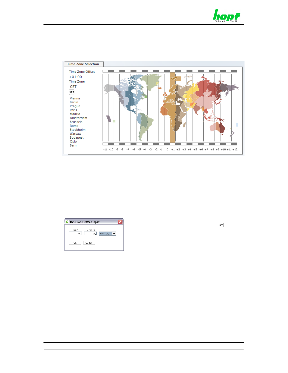
The panel is used to configure the time zone offset to UTC time for calculation of local standard
time. The operational sign designates the direction of the time zone location in relation to the
prime meridian ('+' for east and '-' for west).
Selecting a Time Zone
There are two ways to select a time zone: Either one of the predefined time zones may be
selected by moving the mouse over the world map, which implies the limitation that not every
theoretically possible time zone offset may be selected. A list of cities within the time zone that
is marked in the map helps finding the correct time zone for a certain place on earth. Of course,
no warranty of any kind is given for the correctness of these lists and other information, and
local time zones are always due to change. Map and lists are merely for convenience.
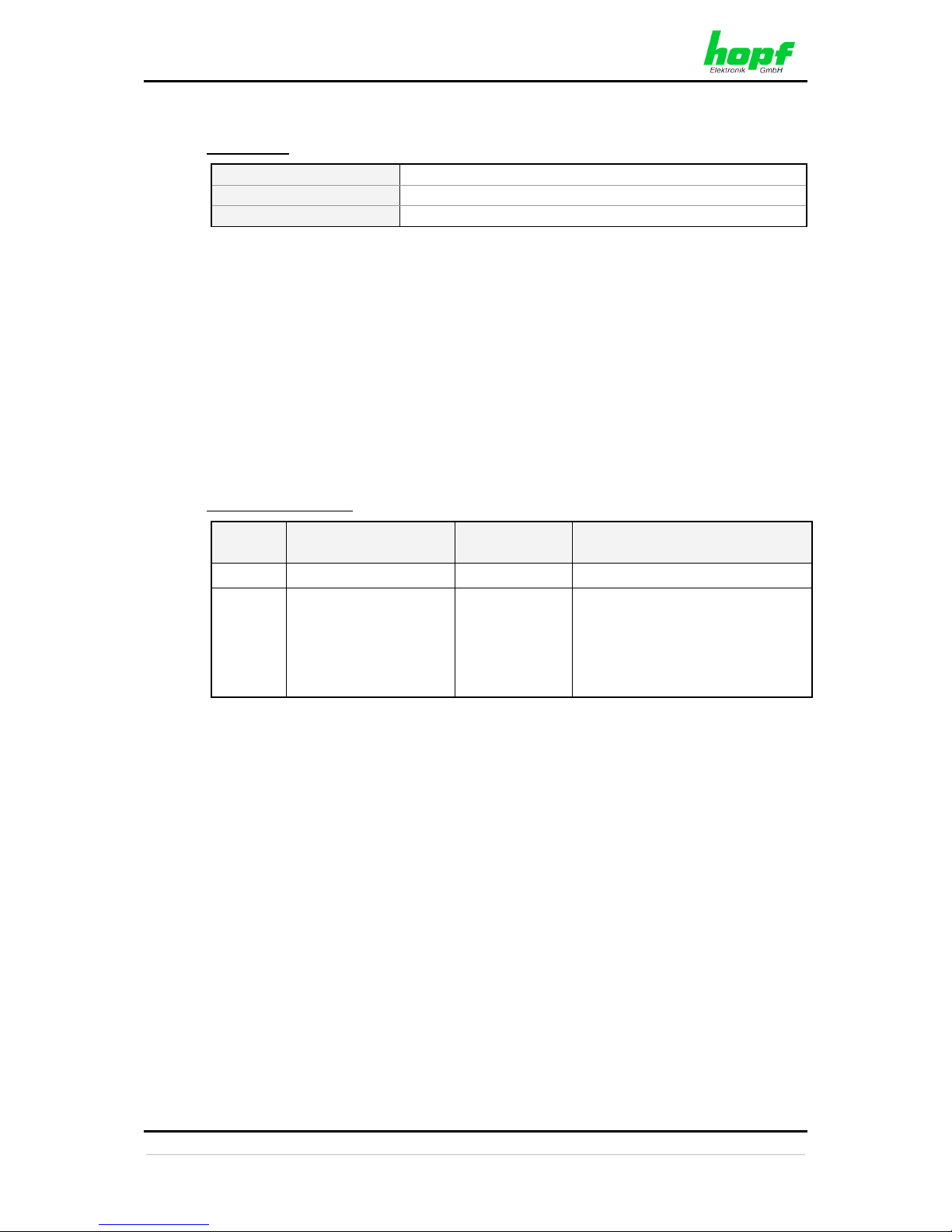
A time zone can be specified manually too (up to
minute precision). For this purpose, the button
will open a dialog allowing input of the offset
as values direction, hours and minutes.
Page 25
HMC (HOPF MANAGEMENT CONSOLE) SOFTWARE
8024GPS - GPS Sync Module - V02.00 25 / 76
hopf
Elektronik GmbH
Nottebohmstr. 41 • D-58511 Lüdenscheid • Tel.: +49 (0)2351 9386-86 • Fax: +49 (0)2351 9386-93 • Internet: http://www.hopf.com • E-Mail: [email protected]
Value range
Operational sign
'+' (east) or '–' (west)
Hours
00 ... 13 – max. +/- 13:00h
Minutes
00 ... 59
The operational sign designates the direction in which the local time differs from UTC time:
'+' corresponds to east of the prime meridian (Greenwich)
'-' corresponds to west of the prime meridian (Greenwich)
As most countries of the world select their time offset in whole hours the input is also in steps
of one hour:
e.g. + 05:00 or - 11:00
However, some countries operate with smaller time steps; thus minute-by-minute entry is also
possible:
e.g. + 05:30 or - 08:45
Example for Germany:
UTC
Local Time
Time Offset to
be set:
Comment
13:00:00
14:00:00 (winter time)
+01:00
13:00:00
15:00:00 (summer
time)
+01:00
The time difference of two hours is
calculated by:
+01:00h time zone offset and
+01:00h for the daylight saving
time offset (changeover points in
time must be set).
Page 26
HMC (HOPF MANAGEMENT CONSOLE) SOFTWARE
26 / 76 8024GPS - GPS Sync Module - V02.00
hopf
Elektronik GmbH
Nottebohmstr. 41 • D-58511 Lüdenscheid • Tel.: +49 (0)2351 9386-86 • Fax: +49 (0)2351 9386-93 • Internet: http://www.hopf.com • E-Mail: [email protected]
3.6.2 System – Tab
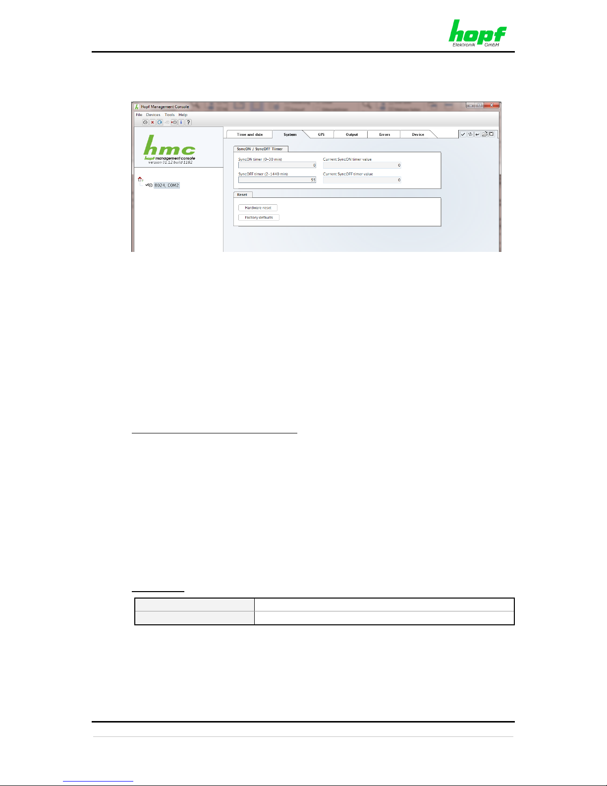
3.6.2.1 SyncON / SyncOFF
These timers can be used to delay the change of status from QUARTZ to SYNC (SyncON
Timer) and from SYNC to QUARTZ (SyncOFF Timer).
The SyncOFF timer is used to bypass reception failure for operation free of fault messages in
difficult reception conditions.
In the event of a synchronization source reception failure (GPS in this instance), the resynchronization of the system to quartz status (QUEX) is delayed by the configured value. The
system continues to run in synchronous status (SYOF) on the internally regulated, highly
accurate quartz base during this period.
This setting depends primarily on the desired freewheel accuracy.
Example freewheel accuracy calculation
In order to calculate the maximum value to be set for the SyncOFF timer, the desired minimum
system accuracy is divided by the freewheel accuracy value of the quartz. If, for example, the
freewheel accuracy is 1x10E-6 and the desired minimum system accuracy is 5msec. the
following calculation results:
0.005s / 1x10E-6 = 5000s = 83 minutes 20 seconds
The max. value to be set for the SyncOFF timer is thus 83 minutes.
The SyncON timer is used for systems operating on a highly accurate, regulated quartz base
to ensure that the system does not synchronize before the quartz base has been accurately
regulated. This timer should be set to 00 as default value on Module 8024GPS.
Value range
SyncON
00 ... 30 min
SyncOFF
0002 ... 1440 min
Page 27
HMC (HOPF MANAGEMENT CONSOLE) SOFTWARE
8024GPS - GPS Sync Module - V02.00 27 / 76
hopf
Elektronik GmbH
Nottebohmstr. 41 • D-58511 Lüdenscheid • Tel.: +49 (0)2351 9386-86 • Fax: +49 (0)2351 9386-93 • Internet: http://www.hopf.com • E-Mail: [email protected]
3.6.2.2 Reset
Hardware reset
This button is used to trigger a hardware reset of the module. This leads to a defined restart
of the module's microcontroller.
This function has no effect on the failsafe stored data.
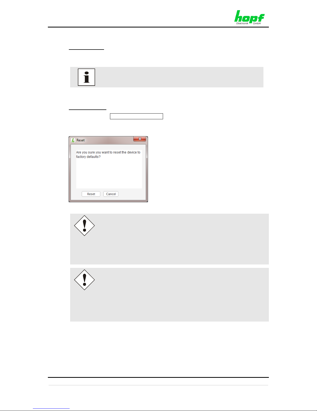
Factory defaults
After activating the Factory defaults - button and an additional confirmation dialog the
settings of Module 8024GPS are reset to factory default.
After setting the Sync Source to factory default values the GPS receiver
needs up to 13 minutes of satellite reception in order to generate the correct
information on the leap second from the GPS data. Only then the Sync
Source (here Module 8024GPS) can be synchronized.
During this time (however only when the GPS receiver really receives
satellites) the following message is displayed in the tab Module Errors:
GPS Receiver in raw data mode - no synchronisation
As long as the DST changeover times for daylight saving time and the time
zone offset are not initially configured after a factory default of the Sync Source
(here Module 8024GPS) the following message is displayed in the tab Module
Errors:
Missing data for Time Zone Offset
and/or
Missing or incomplete data for daylight saving time (DST)
Page 28
HMC (HOPF MANAGEMENT CONSOLE) SOFTWARE
28 / 76 8024GPS - GPS Sync Module - V02.00
hopf
Elektronik GmbH
Nottebohmstr. 41 • D-58511 Lüdenscheid • Tel.: +49 (0)2351 9386-86 • Fax: +49 (0)2351 9386-93 • Internet: http://www.hopf.com • E-Mail: [email protected]
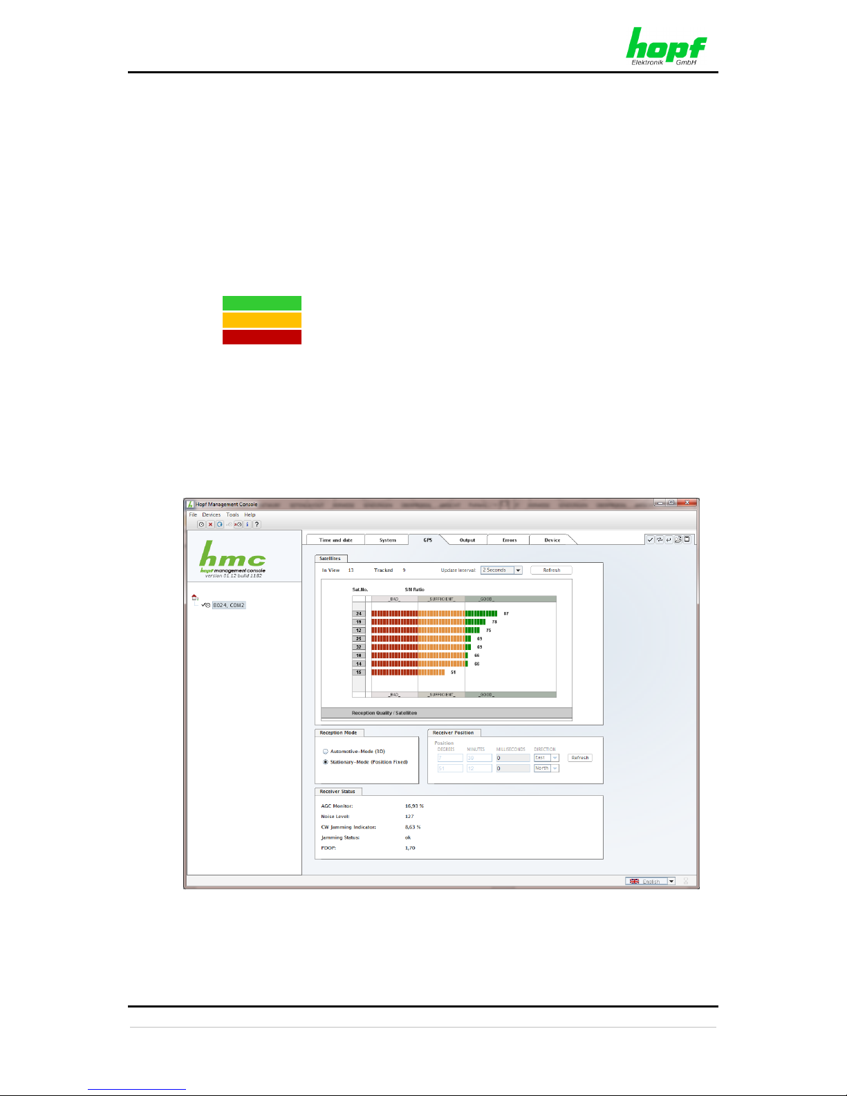
3.6.3 GPS – Tab
In this tab the following information is indicated with read-only access:
Satellites in View
Number of theoretically visible satellites relating to time and location of the GPS receiver.
Satellites Tracked
Effective number of tracked satellites used for synchronization.
Satellites Number – S/N Ratio
Overview of actually tracked GPS satellites showing the satellite identification number and
reception quality:
Green
Good reception quality
Yellow
Sufficient reception quality
Red
Poor reception quality
Receiver Position
Display of the actual position calculated by the GPS receiver.
Receiver Status
Display of the internal GPS receiver status values for analysing the GPS receiver in case of
support issues.
Page 29
HMC (HOPF MANAGEMENT CONSOLE) SOFTWARE
8024GPS - GPS Sync Module - V02.00 29 / 76
hopf
Elektronik GmbH
Nottebohmstr. 41 • D-58511 Lüdenscheid • Tel.: +49 (0)2351 9386-86 • Fax: +49 (0)2351 9386-93 • Internet: http://www.hopf.com • E-Mail: [email protected]
Reception Mode
In this panel the GPS reception mode is adjusted and displayed. The accuracy of the time
evaluation is defined by the exact position calculation of the installation site. For this calculation
(3D evaluation) it is necessary to receive information from at least four (4) satellites. The signal
runtime to several satellites is determined from the calculated position and the precise second
mark is generated from their mean value.
Stationary Mode (Position Fixed) – Standard operation
In Stationary Mode (Fixed position), the GPS receiver calculates its accuracy based on a fixed
position. If four or more satellites are received in this mode, the exact location is updated
automatically.
In this mode, a synchronization with a changing position is not possible.
Automotive (3D)
The automotive (3D) mode allows the use of Sync Module 8024GPS at mobile locations
(except aircraft).
3.6.4 Output – Tab
This Chapter describes the additional functions of Sync Module 8024GPS.
The
hmc
software identifies the actual available device specific signal generators and only
displays the corresponding tabs like (PPS / DCF77 / IRIG-B / …).
The delivery status of the customer specific device can be found in the accompanying
configuration documentation.
Subsequent activation of the Output functionality is not possible on site.
Page 30
HMC (HOPF MANAGEMENT CONSOLE) SOFTWARE
30 / 76 8024GPS - GPS Sync Module - V02.00
hopf
Elektronik GmbH
Nottebohmstr. 41 • D-58511 Lüdenscheid • Tel.: +49 (0)2351 9386-86 • Fax: +49 (0)2351 9386-93 • Internet: http://www.hopf.com • E-Mail: [email protected]
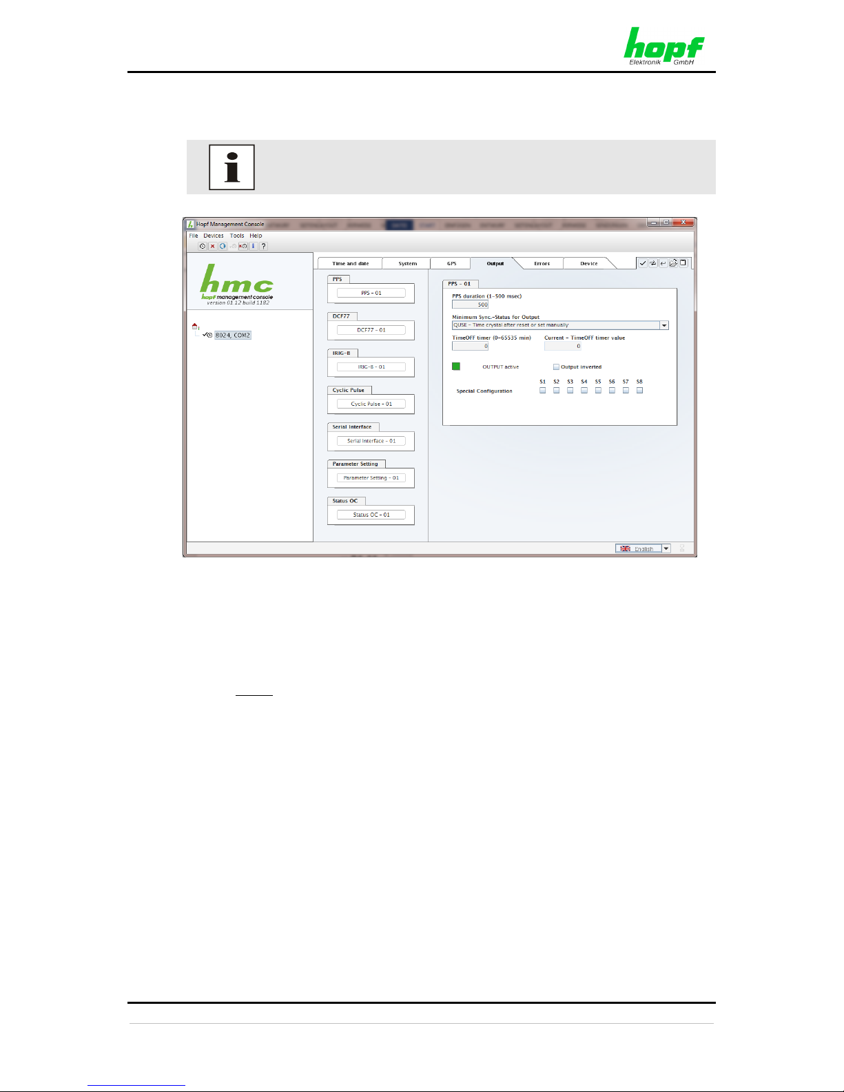
3.6.4.1 PPS - optional hardware necessary
The signal generation for the output of a PPS pulse (1Hz) may be configured in this panel.
For the output of this signal additional hardware (at system level) is
required (see system manual if applicable).
3.6.4.1.1 PPS duration
This section serves to select the pulse width to be transmitted. Basically it is possible to specify
the pulse width in milliseconds.
Possible values for the pulse duration:
• Minimum: 1 msec
• Maximum: 500 msec
3.6.4.1.2 Minimum Sync.-Status - Status-Dependent Pulse Output
Signal output can be configured only to be generated when the Sync Module 8024GPS has
reached a minimum synchronization status. As soon as this minimum synchronization status
drops below this value during operation, the signal output stops unless the TimeOFF Timer
has been set greater than 0. In this case the output is done for the duration of the TimeOFF
Timer despite the minimum synchronization status for the output falls below the configured
value.
Page 31
HMC (HOPF MANAGEMENT CONSOLE) SOFTWARE
8024GPS - GPS Sync Module - V02.00 31 / 76
hopf
Elektronik GmbH
Nottebohmstr. 41 • D-58511 Lüdenscheid • Tel.: +49 (0)2351 9386-86 • Fax: +49 (0)2351 9386-93 • Internet: http://www.hopf.com • E-Mail: [email protected]
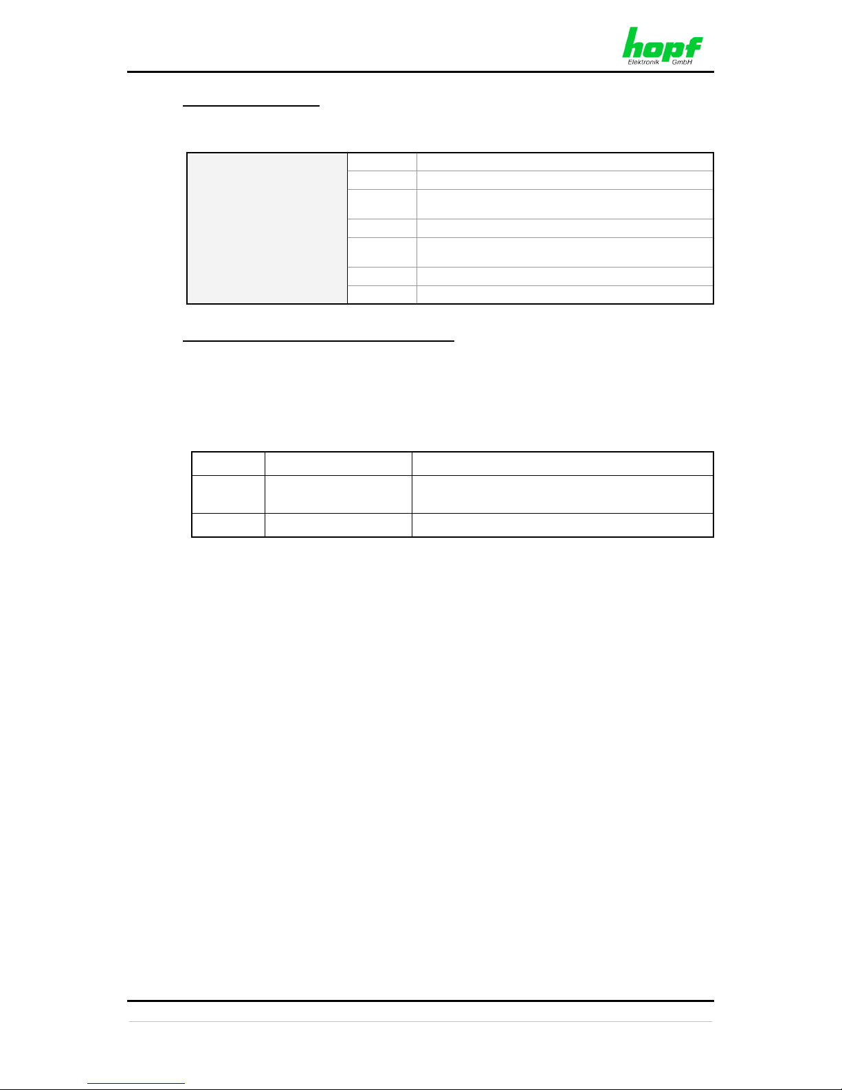
Range of Sync.-Status
The synchronization status is represented from the bottom of the following table (INVA) up
with increasing quality.
Synchronisation Status
SYNC
Time synchronized + quartz control started/running
SYOF
Time synchronized + SyncOFF running
SYSI
Time synchronized as simulation mode
(with no actual GPS reception)
QUON
Quartz/crystal time + SyncON running
QUEX
Quartz/crystal time (in freewheel after synchronization
failure Board was already synchronized)
QUSE
Quartz/crystal time after reset or manually set
INVA
Invalid time
Value range TimeOFF timer = 0 to 65635min.
3.6.4.1.3 Status of the Signal Output
The status of the output is stated via a display element with the following color and text
indications:
GREEN
OUTPUT active
There is a signal output
YELLOW
OUTPUT
+ TimeOFF active
There is a signal output
for the duration of the TimeOFF Timer
RED
OUTPUT blocked
There is no signal output
3.6.4.1.4 Output inverted – Polarity of the output Pulse
All outputs stated in the system manuals of the according devices are related to the DEFAULT
setting: Output not inverted.
If nevertheless the inverting of the output signal has to be configured the "Output inverted"
checkbox has to be enabled.
3.6.4.1.5 Special Configuration
If used, the correct settings are described in the additional system manual of the customerspecific device.
Otherwise for S1-S8 the DEFAULT-setting (all checkboxes disabled) should not be changed
due to compatibility reasons.
Page 32
HMC (HOPF MANAGEMENT CONSOLE) SOFTWARE
32 / 76 8024GPS - GPS Sync Module - V02.00
hopf
Elektronik GmbH
Nottebohmstr. 41 • D-58511 Lüdenscheid • Tel.: +49 (0)2351 9386-86 • Fax: +49 (0)2351 9386-93 • Internet: http://www.hopf.com • E-Mail: [email protected]
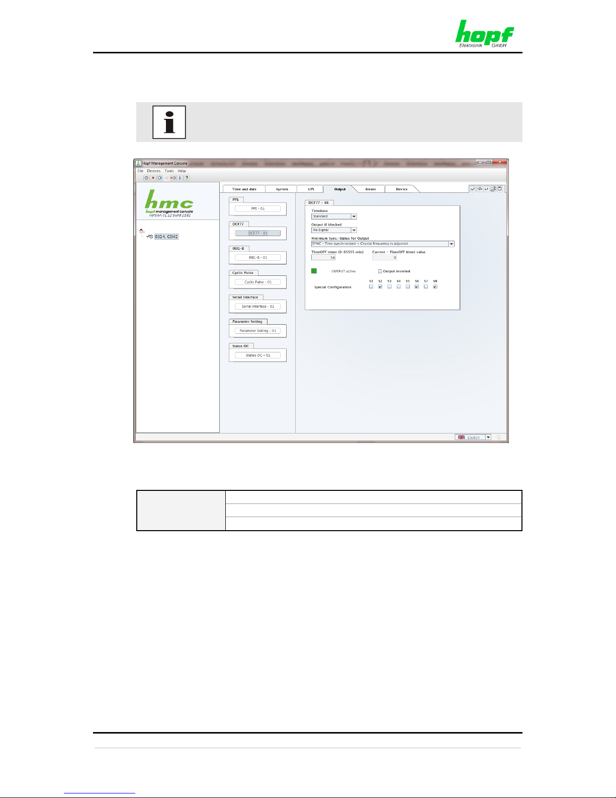
3.6.4.2 DCF77 - optional hardware necessary
The signal generation for the output of a DCF77 pulse (1Hz) may be configured in this panel.
For the output of this signal additional hardware (at system level) is
required (see system manual if applicable).
3.6.4.2.1 Time Base of the Transmitted DCF77 Pulse
Time Base
Local Time
Standard Time
UTC Time
In general the local time is set as the base. This time leaps forward/back 1 hour every daylight
saving time changeover. The standard or UTC time must be selected as the base if automatic
daylight saving time changeover shall be suppressed.
When setting standard time (winter time), the time offset to local summer time is minus 1 hour.
Standard time runs continuously (without time leap) throughout the whole year.
When setting UTC, the world time (formerly GMT) is used as the time base. This time base
also runs continuously (without time leap) throughout the whole year.
Page 33
HMC (HOPF MANAGEMENT CONSOLE) SOFTWARE
8024GPS - GPS Sync Module - V02.00 33 / 76
hopf
Elektronik GmbH
Nottebohmstr. 41 • D-58511 Lüdenscheid • Tel.: +49 (0)2351 9386-86 • Fax: +49 (0)2351 9386-93 • Internet: http://www.hopf.com • E-Mail: [email protected]
3.6.4.2.2 Output if blocked - Signal Output in the event of a Fault
Using this menu item the interference reaction of the DCF77 pulse can be controlled unless
the system status is lower than the reference value.
Fault signal
2 Hz Signal:
If the status of Sync Module 8024GPS is lower than the
reference value, a 2Hz signal instead of the DCF77 pulse is
provided.
No signal
If the status of Sync Module 8024GPS is lower than the
reference value there is no signal output.
Transmission of a 2Hz pulse in the event of a fault allows the connected
devices to monitor for line breakage.
3.6.4.2.3 Minimum Sync.-Status - Status-Dependent Pulse Output
The signal output can be adjusted only to be generated when the Sync Module 8024GPS has
reached a minimum synchronization status. As soon as this minimum synchronization status
drops below this value during operation, the signal output stops unless the TimeOFF Timer
has been set greater than 0. In this case the output is done for the duration of the TimeOFF
Timer despite the minimum synchronization status for the output falls below the set value.
Range of Sync.-Status
The synchronization status is represented from the bottom of the following table (INVA) up
with increasing quality.
Synchronisation Status
SYNC
Time synchronized + quartz control started/running
SYOF
Time synchronized + SyncOFF running
SYSI
Time synchronized as simulation mode
(with no actual GPS reception)
QUON
Quartz/crystal time + SyncON running
QUEX
Quartz/crystal time (in freewheel after synchronization
failure Board was already synchronized)
QUSE
Quartz/crystal time after reset or manually set
INVA
Invalid time
Value range TimeOFF timer = 0 to 65635min.
3.6.4.2.4 Status of the Signal Output
The status of the output is stated via a display element with the following color and text
indications:
GREEN
OUTPUT active
There is a signal output
YELLOW
OUTPUT
+ TimeOFF active
There is a signal output
for the duration of the TimeOFF Timer
RED
OUTPUT blocked
There is no signal output
Page 34

HMC (HOPF MANAGEMENT CONSOLE) SOFTWARE
34 / 76 8024GPS - GPS Sync Module - V02.00
hopf
Elektronik GmbH
Nottebohmstr. 41 • D-58511 Lüdenscheid • Tel.: +49 (0)2351 9386-86 • Fax: +49 (0)2351 9386-93 • Internet: http://www.hopf.com • E-Mail: [email protected]
3.6.4.2.5 Output inverted – Polarity of the output DCF77 Pulse
All outputs stated in the system manuals of the according devices are related to the DEFAULT
setting: Output not inverted.
If nevertheless the inverting of the output signal has to be configured the "Output inverted"
checkbox has to be enabled.
3.6.4.2.6 Special Configuration
If used, the correct settings are described in the additional system manual of the customerspecific device.
Otherwise for S1-S8 the DEFAULT-setting (all checkboxes disabled) should not be changed
due to compatibility reasons.
Page 35
HMC (HOPF MANAGEMENT CONSOLE) SOFTWARE
8024GPS - GPS Sync Module - V02.00 35 / 76
hopf
Elektronik GmbH
Nottebohmstr. 41 • D-58511 Lüdenscheid • Tel.: +49 (0)2351 9386-86 • Fax: +49 (0)2351 9386-93 • Internet: http://www.hopf.com • E-Mail: [email protected]
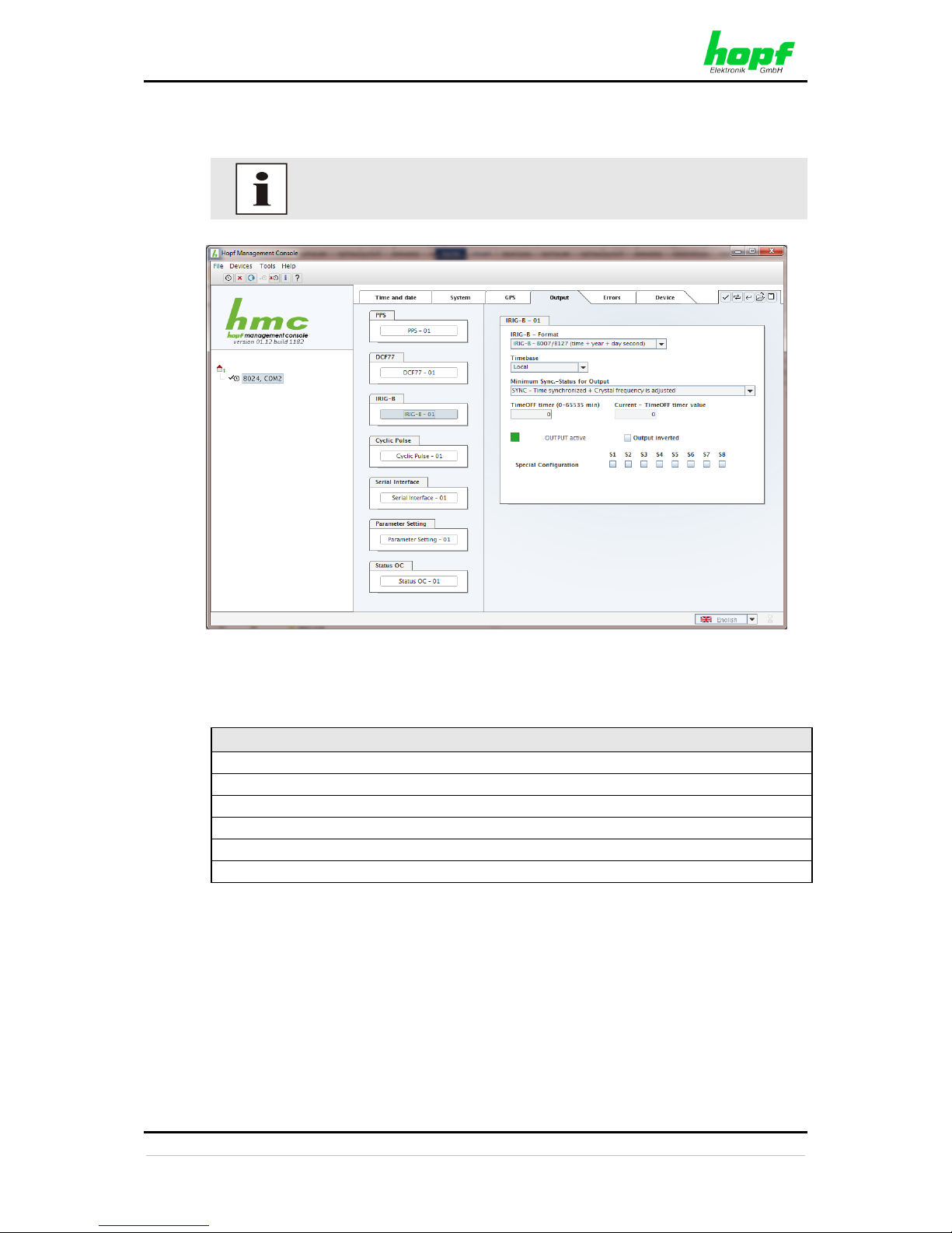
3.6.4.3 IRIG-B- optional hardware nesessary
The signal generation for the output of an IRIG-B signal may be configured in this panel.
For the output of this signal additional hardware (at system level) is
required (see system manual if applicable).
3.6.4.3.1 Selection of the IRIG-B Format
Following IRIG-B output formats are available:
Selection of Output Format IRIG-B / IEEE C37.118 / AFNOR
IRIG-B / B007+B127 (time, year, second of the day)
IRIG-B / B003+B123( time, second of the day)
IRIG-B / B006+B126 (time, year)
IRIG-B / B002+B122 (time)
IEEE C37.118 (previously IEEE 1344)
AFNOR NF S87-500
Page 36
HMC (HOPF MANAGEMENT CONSOLE) SOFTWARE
36 / 76 8024GPS - GPS Sync Module - V02.00
hopf
Elektronik GmbH
Nottebohmstr. 41 • D-58511 Lüdenscheid • Tel.: +49 (0)2351 9386-86 • Fax: +49 (0)2351 9386-93 • Internet: http://www.hopf.com • E-Mail: [email protected]
3.6.4.3.2 Timebase – Timebase of the output IRIG-B Signal
Timebase
Local Time
Standard Time
UTC Time
In general the local time is set as the base. This time leaps forward/back 1 hour every daylight
saving time changeover. The standard or UTC time must be selected as the base if automatic
daylight saving time changeover shall be suppressed.
When setting standard time (winter time), the time offset to local summer time is minus 1 hour.
Standard time runs continuously (without time leap) throughout the whole year.
When setting UTC, the world time (formerly GMT) is used as the time base. This time base
also runs continuously (without time leap) throughout the whole year.
3.6.4.3.3 Minimum Sync.-Status - Status-Dependent Pulse Output
The signal output can be adjusted only to be generated when the Sync Module 8024GPS has
reached a minimum synchronization status. As soon as this minimum synchronization status
drops below this value during operation, the signal output stops unless the TimeOFF Timer
has been set greater than 0. In this case the output is done for the duration of the TimeOFF
Timer despite the minimum synchronization status for the output falls below the set value.
Range of Sync.-Status
The synchronization status is represented from the bottom of the following table (INVA) up
with increasing quality.
Synchronisation Status
SYNC
Time synchronized + quartz control started/running
SYOF
Time synchronized + SyncOFF running
SYSI
Time synchronized as simulation mode
(with no actual GPS reception)
QUON
Quartz/crystal time + SyncON running
QUEX
Quartz/crystal time (in freewheel after synchronization
failure Board was already synchronized)
QUSE
Quartz/crystal time after reset or manually set
INVA
Invalid time
Value range TimeOFF timer = 0 to 65635min.
3.6.4.3.4 Status of the Signal Output
The status of the output is stated via a display element with the following color and text
indications:
GREEN
OUTPUT active
There is a signal output
YELLOW
OUTPUT
+ TimeOFF active
There is a signal output
for the duration of the TimeOFF Timer
RED
OUTPUT blocked
There is no signal output
Page 37
HMC (HOPF MANAGEMENT CONSOLE) SOFTWARE
8024GPS - GPS Sync Module - V02.00 37 / 76
hopf
Elektronik GmbH
Nottebohmstr. 41 • D-58511 Lüdenscheid • Tel.: +49 (0)2351 9386-86 • Fax: +49 (0)2351 9386-93 • Internet: http://www.hopf.com • E-Mail: [email protected]
3.6.4.3.5 Output inverted – Polarity of the output Pulse
All outputs stated in the system manuals of the according devices are related to the DEFAULT
setting: Output not inverted.
If nevertheless the inverting of the output signal has to be configured the "Output inverted"
checkbox has to be enabled.
3.6.4.3.6 Special Configuration
If used, the correct settings are described in the additional system manual of the customerspecific device.
Otherwise for S1-S8 the DEFAULT-setting (all checkboxes disabled) should not be changed
due to compatibility reasons.
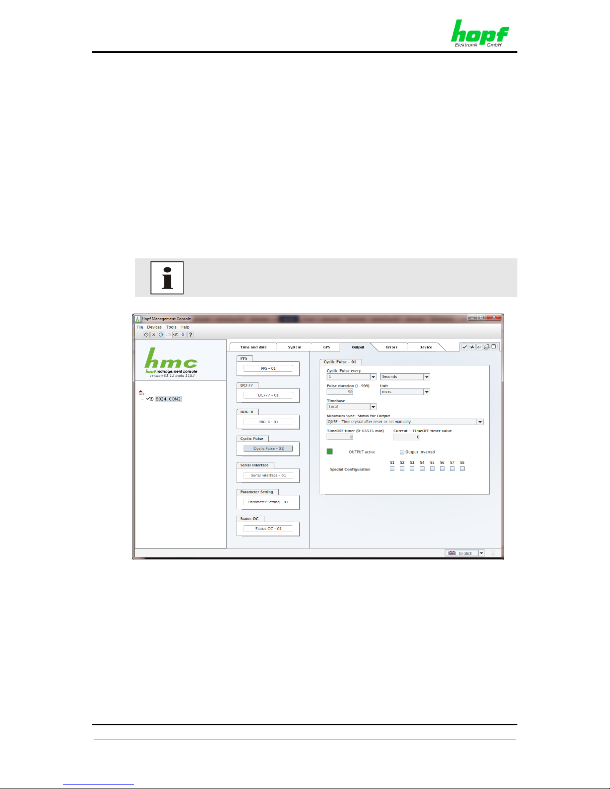
3.6.4.4 Cyclic Pulse - optional hardware nesessary
The signal generation for the output of cyclic pulses may be configured in this panel.
For the output of this signal additional hardware (at system level) is
required (see system manual if applicable).
3.6.4.4.1 Cyclic Pulse every
This section is used to select the pulse to be transmitted. Possible pulses are:
• Pulses every second: every 1, 2, 3, 4, 5, 6, 10, 12, 15, 20 or 30 seconds
• Pulses every minute: every 1, 2, 3, 4, 5, 6, 10, 12, 15, 20 or 30 minutes
• Pulses every hour: every 1, 2, 3, 4, 6, 8, 12 or 24 hours
Page 38
HMC (HOPF MANAGEMENT CONSOLE) SOFTWARE
38 / 76 8024GPS - GPS Sync Module - V02.00
hopf
Elektronik GmbH
Nottebohmstr. 41 • D-58511 Lüdenscheid • Tel.: +49 (0)2351 9386-86 • Fax: +49 (0)2351 9386-93 • Internet: http://www.hopf.com • E-Mail: [email protected]
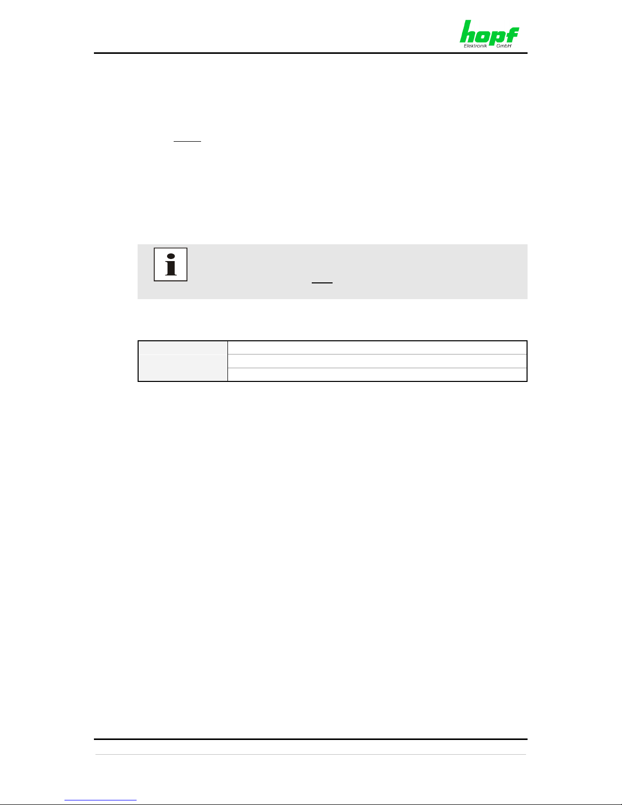
3.6.4.4.2 Pulse duration
This section is used to select the pulse width to be transmitted. Basically it is possible to specify
the pulse width in milliseconds or seconds.
Possible values for the pulse duration:
• Minimum: 1
• Maximum: 999
Possible values for the pulse duration unit:
• Second (sec)
• Millisecond (msec)
Certain inputs are automatically corrected:
• Value > 999 are automatically corrected to 999.
• The pulse lengths must be at least 20msec shorter than the pulse
interval.
3.6.4.4.3 Time Base of the Transmitted Cyclic Pulse
Time Base
Local Time
Standard Time
UTC Time
In general the local time is set as the base. This time leaps forward/back 1 hour every daylight
saving time changeover. The standard or UTC time must be selected as the base if automatic
daylight saving time changeover shall be suppressed.
When setting standard time (winter time), the time offset to local summer time is minus 1 hour.
Standard time runs continuously (without time leap) throughout the whole year.
When setting UTC, the world time (formerly GMT) is used as the time base. This time base
also runs continuously (without time leap) throughout the whole year.
3.6.4.4.1 Minimum Sync.-Status - Status-Dependent Pulse Output
The signal output can be adjusted only to be generated when the Sync Module 8024GPS has
reached a minimum synchronization status. As soon as this minimum synchronization status
drops below this value during operation, the signal output stops unless the TimeOFF Timer
has been set greater than 0. In this case the output is done for the duration of the TimeOFF
Timer despite the minimum synchronization status for the output falls below the set value.
Page 39
HMC (HOPF MANAGEMENT CONSOLE) SOFTWARE
8024GPS - GPS Sync Module - V02.00 39 / 76
hopf
Elektronik GmbH
Nottebohmstr. 41 • D-58511 Lüdenscheid • Tel.: +49 (0)2351 9386-86 • Fax: +49 (0)2351 9386-93 • Internet: http://www.hopf.com • E-Mail: [email protected]
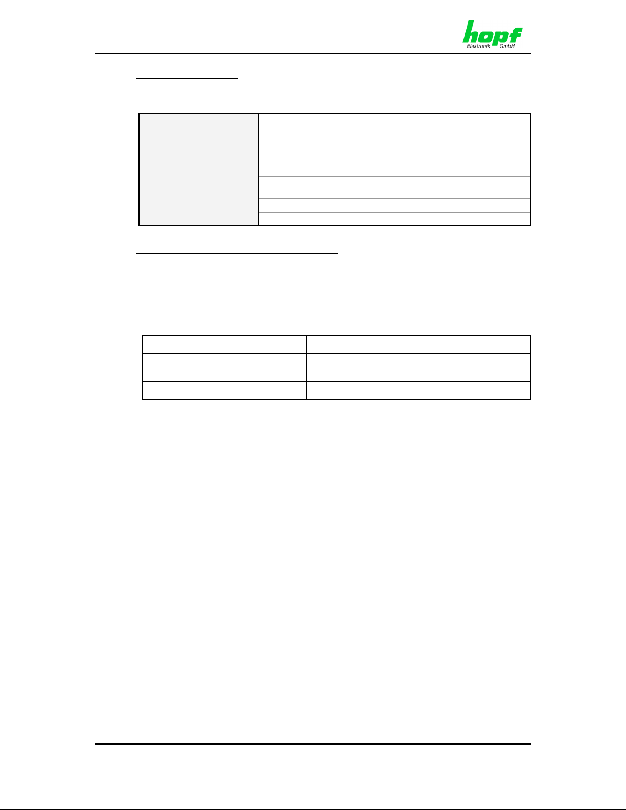
Range of Sync.-Status
The synchronization status is represented from the bottom of the following table (INVA) up
with increasing quality.
Synchronisation Status
SYNC
Time synchronized + quartz control started/running
SYOF
Time synchronized + SyncOFF running
SYSI
Time synchronized as simulation mode
(with no actual GPS reception)
QUON
Quartz/crystal time + SyncON running
QUEX
Quartz/crystal time (in freewheel after synchronization
failure Board was already synchronized)
QUSE
Quartz/crystal time after reset or manually set
INVA
Invalid time
Value range TimeOFF timer = 0 to 65635min.
3.6.4.4.2 Status of the Signal Output
The status of the output is stated via a display element with the following color and text
indications:
GREEN
OUTPUT active
There is a signal output
YELLOW
OUTPUT
+ TimeOFF active
There is a signal output
for the duration of the TimeOFF Timer
RED
OUTPUT blocked
There is no signal output
3.6.4.4.3 Output inverted – Polarity of the output Pulse
All outputs stated in the system manuals of the according devices are related to the DEFAULT
setting: Output not inverted.
If nevertheless the inverting of the output signal has to be configured the "Output inverted"
checkbox has to be enabled.
3.6.4.4.4 Special Configuration
If used, the correct settings are described in the additional system manual of the customerspecific device.
Otherwise for S1-S8 the DEFAULT-setting (all checkboxes disabled) should not be changed
due to compatibility reasons.
Page 40
HMC (HOPF MANAGEMENT CONSOLE) SOFTWARE
40 / 76 8024GPS - GPS Sync Module - V02.00
hopf
Elektronik GmbH
Nottebohmstr. 41 • D-58511 Lüdenscheid • Tel.: +49 (0)2351 9386-86 • Fax: +49 (0)2351 9386-93 • Internet: http://www.hopf.com • E-Mail: [email protected]
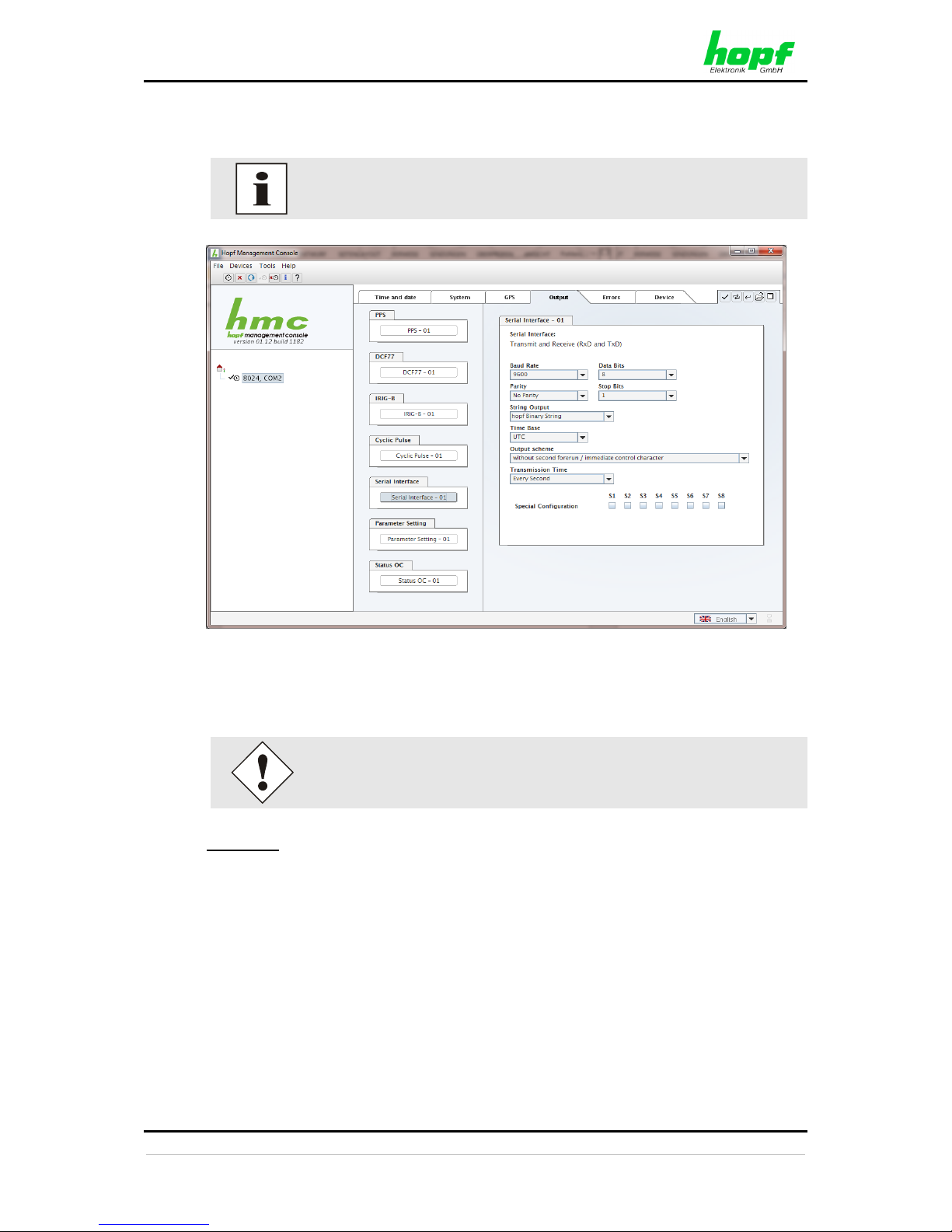
3.6.4.5 Serial Interface - optional hardware necessary
The serial data string generation may be configured in this panel.
For the output of serial data string additional hardware (at system level) is
required (see system manual if applicable).
3.6.4.5.1 Serial Interface parameter
Data strings are available by selection to change automatically the serial
parameter.
Baud Rate
• 9600 baud
• 2400 baud
• 4800 baud
• 9600 baud
• 19200 baud
• 38400 baud
• 57600 baud
• 115000 baud
Page 41
HMC (HOPF MANAGEMENT CONSOLE) SOFTWARE
8024GPS - GPS Sync Module - V02.00 41 / 76
hopf
Elektronik GmbH
Nottebohmstr. 41 • D-58511 Lüdenscheid • Tel.: +49 (0)2351 9386-86 • Fax: +49 (0)2351 9386-93 • Internet: http://www.hopf.com • E-Mail: [email protected]
Data bits
Possible settings are:
• 8 for 8 data bits
• 7 for 7 data bits
Parity
Possible settings are:
• No Parity
• Even Parity
• Odd Parity
Stop Bits
Possible settings are:
• 1 for 1 stop bit
• 2 for 2 stop bits
3.6.4.5.2 Timebase – Timebase of the output serial data string
Timebase
Local Time
Standard Time
UTC Time
In general the local time is set as the base. This time leaps forward/back 1 hour every daylight
saving time changeover. The standard or UTC time must be selected as the base if automatic
daylight saving time changeover shall be suppressed.
When setting standard time (winter time), the time offset to local summer time is minus 1 hour.
Standard time runs continuously (without time leap) throughout the whole year.
When setting UTC, the world time (formerly GMT) is used as the time base. This time base
also runs continuously (without time leap) throughout the whole year.
3.6.4.5.3 Output scheme
The output scheme for the transmission must be selected here:
• Without second forerun / immediate control character
• With second forerun / immediate control character
• With second forerun / control character every second
• With second forerun / control character delayed every second
3.6.4.5.4 Transmission Time
• Every Second
• EveryMinute
• Every Hour
• Remote
Page 42
HMC (HOPF MANAGEMENT CONSOLE) SOFTWARE
42 / 76 8024GPS - GPS Sync Module - V02.00
hopf
Elektronik GmbH
Nottebohmstr. 41 • D-58511 Lüdenscheid • Tel.: +49 (0)2351 9386-86 • Fax: +49 (0)2351 9386-93 • Internet: http://www.hopf.com • E-Mail: [email protected]
3.6.4.5.5 Special Configuration
If used, the correct settings are described in the additional system manual of the customerspecific device.
Otherwise for S1-S8 the DEFAULT-setting (all checkboxes disabled) should not be changed
due to compatibility reasons.
3.6.4.5.6 String Output
The string output for the transmission must be selected here:
•
hopf
Binäry String
•
hopf
time Universal
•
hopf
Master/Slave-String
•
hopf
Standard String (6021)
• Trimble Time String (TSIP)
• SINEC H1 Extended
• SAT 1703 Time String
• ABB Melody (CR/LF)
• ABB Melody (LF/CR)
•
hopf
6021 String 2000
• IEC-103 (ASDU Type 6)
3.6.4.5.6.1
hopf
Binary String
The
hopf
Binary String can be used to synchronize slave systems with the time data of the
master system.
Required:
• Transmision Time every second
• With second forerun / control character every second
• 9600 baud, 8 bit, 1 stop bit, no parity
Example:
(STX):TIME:80;0233D88F08;07E0;003C;F4108014*6B(CR)(LF) (ETX)
3.6.4.5.6.2
hopf
time Universal
The
hopf
time Universal String can be used to synchronize slave systems with the time data
of the master system.
Required:
• Transmision Time every second
• With second forerun / control character every second
• UTC time
• 9600 baud, 8 bit, 1 stop bit, no parity
Example:
(STX)731144501904201602+0000FFFF*23(CR)(LF) (ETX)
Page 43
HMC (HOPF MANAGEMENT CONSOLE) SOFTWARE
8024GPS - GPS Sync Module - V02.00 43 / 76
hopf
Elektronik GmbH
Nottebohmstr. 41 • D-58511 Lüdenscheid • Tel.: +49 (0)2351 9386-86 • Fax: +49 (0)2351 9386-93 • Internet: http://www.hopf.com • E-Mail: [email protected]
3.6.4.5.6.3
hopf
Master/Slave-String
The
hopf
Master/Slave-String can be used to synchronize slave systems with the time data
of the master system.
The
hopf
Master/Slave-String transmits:
• the full time information (hour, minute, second)
• the date (day, month, year [2 digits])
• the difference time local to UTC (hour, minute)
• the day of the week
• status information (announcement of DST changeover, announcement of a leap
second and the status of reception of the
hopf
Master/Slave-String source)
3.6.4.5.6.3.1 Specified Settings
Required:
The following settings are required for the synchronization of the
hopf
slave-systems:
• Normally points of time every minute, depending on system
also every second
• output second forerun
• ETX on the second change; selectable: data string at the
beginning or at the end of the 59. second.
• local time
• 9600 baud, 8 bit, 1 stop bit, no parity
Received data on the serial interface that are not specified in the pertinent
data string might disturb and interrupt the cyclic string output.
The receiving synchronization interface should be set to "transmitting on
request" for Sub-Master (Slave) Systems.
Page 44
HMC (HOPF MANAGEMENT CONSOLE) SOFTWARE
44 / 76 8024GPS - GPS Sync Module - V02.00
hopf
Elektronik GmbH
Nottebohmstr. 41 • D-58511 Lüdenscheid • Tel.: +49 (0)2351 9386-86 • Fax: +49 (0)2351 9386-93 • Internet: http://www.hopf.com • E-Mail: [email protected]
3.6.4.5.6.3.2 Structure
Character No.
Meaning
Hex-Value
1
STX (start of text)
$02 2 status
$30-39, $41-46
3
day of the week
$31-37
4
tens hour
$30-32
5
unit hour
$30-39
6
tens minute
$30-35
7
unit minute
$30-39
8
tens second
$30-36
9
unit second
$30-39
10
tens day
$30-33
11
unit day
$30-39
12
tens month
$30-31
13
unit month
$30-39
14
tens year
$30-39
15
unit year
$30-39
16
difference time tens hour / operational sign
$30-31, $38-39
17
difference time unit hour
$30-39
18
difference time tens minutes
$30-35
19
difference time unit minutes
$30-39
20
LF (line feed)
$0A
21
CR (carriage Return)
$0D
22
ETX (end of text)
$03
The difference time (time zone offset) is transmitted in hours and minutes following the year.
The transmission is done in BCD. The difference time may be up to ± 14.00h.
The operational sign is shown as the highest bit in the hours.
logic 1 = local time before UTC
logic 0 = local time after UTC
Example:
Data String
Tens Difference
Time Nibble
Difference Time
(STX)831234560301960300(LF)(CR)(ETX)
0000
- 03:00h
(STX)831234560301961100(LF)(CR)(ETX)
0001
- 11:00h
(STX)831234560301968230(LF)(CR)(ETX)
1000
+ 02:30h
(STX)831234560301969100(LF)(CR)(ETX)
1001
+ 11:00h
Page 45
HMC (HOPF MANAGEMENT CONSOLE) SOFTWARE
8024GPS - GPS Sync Module - V02.00 45 / 76
hopf
Elektronik GmbH
Nottebohmstr. 41 • D-58511 Lüdenscheid • Tel.: +49 (0)2351 9386-86 • Fax: +49 (0)2351 9386-93 • Internet: http://www.hopf.com • E-Mail: [email protected]
3.6.4.5.6.3.3 Status
b3
b2
b1
b0
Meaning
Status:
x x x 0
no announcement hour
x x x 1
announcement (DST changeover)
x x 0 x
standard time
x x 1 x
daylight saving time (DST)
x 0 x x
no announcement leap second
x 1 x x
announcement leap second
0 x x x
synchronization status code:
INVA / QUSE / QUEX / QUON
1 x x x
synchronization status code:
SYOF / SYNC
Day of the Week:
0 0 0 1
Monday
0 0 1 0
Tuesday
0 0 1 1
Wednesday
0 1 0 0
Thursday
0 1 0 1
Friday
0 1 1 0
Saturday
0 1 1 1
Sunday
Status
Operating Mode
Time
DST changeover
Leap Second
0 = 0000
INVA / QUSE /
QUEX / QUON
standard time
no announcement
no announcement
1 = 0001
INVA / QUSE /
QUEX / QUON
standard time
announcement
no announcement
2 = 0010
INVA / QUSE /
QUEX / QUON
DST
no announcement
no announcement
3 = 0011
INVA / QUSE /
QUEX / QUON
DST
announcement
no announcement
4 = 0100
INVA / QUSE /
QUEX / QUON
standard time
no announcement
announcement
5 = 0101
INVA / QUSE /
QUEX / QUON
standard time
announcement
announcement
6 = 0110
INVA / QUSE /
QUEX / QUON
DST
no announcement
announcement
7 = 0111
INVA / QUSE /
QUEX / QUON
DST
announcement
announcement
8 = 1000
SYOF / SYNC
standard time
no announcement
no announcement
9 = 1001
SYOF / SYNC
standard time
announcement
no announcement
A = 1010
SYOF / SYNC
DST
no announcement
no announcement
B = 1011
SYOF / SYNC
DST
announcement
no announcement
C = 1100
SYOF / SYNC
standard time
no announcement
announcement
D = 1101
SYOF / SYNC
standard time
announcement
announcement
E = 1110
SYOF / SYNC
DST
no announcement
announcement
F = 1111
SYOF / SYNC
DST
announcement
announcement
DST = daylight saving time
3.6.4.5.6.3.4 Example
(STX)841234561807028230(LF)(CR)(ETX)
• It is Thursday 18.07.2002 - 12:34:56 o'clock
• synchronization status code: SYNC
• no announcement of a changeover
• The difference time to UTC is +2.30 h
Page 46
HMC (HOPF MANAGEMENT CONSOLE) SOFTWARE
46 / 76 8024GPS - GPS Sync Module - V02.00
hopf
Elektronik GmbH
Nottebohmstr. 41 • D-58511 Lüdenscheid • Tel.: +49 (0)2351 9386-86 • Fax: +49 (0)2351 9386-93 • Internet: http://www.hopf.com • E-Mail: [email protected]
3.6.4.5.6.4
hopf
Standard String (6021)
Below the
hopf
Standard String is described.
3.6.4.5.6.4.1 Specified Settings
Required:
no
3.6.4.5.6.4.2 Structure
Character No.
Meaning
Hex-Value
1
STX (start of text)
$02 2 status (internal clock status)
$30-39, $41-46
3
day of the week (1=Monday ... 7=Sunday)
for UTC time bit 3 is set to 1 in the day of the
week
$31-37
4
tens hour
$30-32
5
unit hour
$30-39
6
tens minute
$30-35
7
unit minute
$30-39
8
tens second
$30-36
9
unit second
$30-39
10
tens day
$30-33
11
unit day
$30-39
12
tens month
$30-31
13
unit month
$30-39
14
tens year
$30-39
15
unit year
$30-39
16
LF (line feed)
$0A
17
CR (carriage return)
$0D
18
ETX (end of text)
$03
Page 47
HMC (HOPF MANAGEMENT CONSOLE) SOFTWARE
8024GPS - GPS Sync Module - V02.00 47 / 76
hopf
Elektronik GmbH
Nottebohmstr. 41 • D-58511 Lüdenscheid • Tel.: +49 (0)2351 9386-86 • Fax: +49 (0)2351 9386-93 • Internet: http://www.hopf.com • E-Mail: [email protected]
3.6.4.5.6.4.3 Status
The second and the third ASCII-character contain the status and the day of the week.
The status is decoded binary.
b3
b2
b1
b0
Meaning
Status:
x x x 0 no announcement hour
x x x 1 announcement (DST changeover)
x x 0 x standard time
x x 1 x daylight saving time (DST)
0 0 x x synchronization status code: INVA
0 1 x x synchronization status code: QUSE /
QUEX / QUON
1 0 x x synchronization status code: SYOF
1 1 x x synchronization status code: SYNC
Day of the Week:
0 x x x CEST / CET
1 x x x UTC - time
x 0 0 1 Monday
x 0 1 0 Tuesday
x 0 1 1 Wednesday
x 1 0 0 Thursday
x 1 0 1 Friday
x 1 1 0 Saturday
x 1 1 1 Sunday
Status
operation mode
time
announcement SZ-WZ-SZ
0 = 0000
INVA
winter
no announcement
1 = 0001
INVA
winter
announcement
2 = 0010
INVA
summer
no announcement
3 = 0011
INVA
summer
announcement
4 = 0100
QUSE / QUEX / QUON
winter
no announcement
5 = 0101
QUSE / QUEX / QUON
winter
announcement
6 = 0110
QUSE / QUEX / QUON
summer
no announcement
7 = 0111
QUSE / QUEX / QUON
summer
announcement
8 = 1000
SYOF
winter
no announcement
9 = 1001
SYOF
winter
announcement
A = 1010
SYOF
summer
no announcement
B = 1011
SYOF
summer
announcement
C = 1100
SYNC
winter
no announcement
D = 1101
SYNC
winter
announcement
E = 1110
SYNC
summer
no announcement
F = 1111
SYNC
summer
announcement
3.6.4.5.6.4.4 Example
(STX)E4123456180702(LF)(CR)(ETX)
• It is Thursday 18.07.2002 - 12:34:56 o'clock.
• synchronization status code: SYNC
• daylight saving time
• no announcement of a changeover
• ( ) - ASCII-control characters e.g. (STX)
Page 48

HMC (HOPF MANAGEMENT CONSOLE) SOFTWARE
48 / 76 8024GPS - GPS Sync Module - V02.00
hopf
Elektronik GmbH
Nottebohmstr. 41 • D-58511 Lüdenscheid • Tel.: +49 (0)2351 9386-86 • Fax: +49 (0)2351 9386-93 • Internet: http://www.hopf.com • E-Mail: [email protected]
3.6.4.5.6.5 Trimble Time String (TSIP)
The Trimble Time String (TSIP) can be used to synchronize slave systems with the time data
of the master system.
Example in Hex description (not ASCII):
10 8F 0B 00 00 41 0A 49 00 00 00 00 00 13 04 07 E0 00 00 00 00 00 00 00 00 00 00 00 00
00 00 00 00 00 00 00 00 00 00 00 00 00 00 00 00 00 00 00 00 00 00 00 00 00 00 00 00 00 00
00 00 00 00 00 00 00 00 00 00 00 00 00 00 00 00 00 10 03
Page 49
HMC (HOPF MANAGEMENT CONSOLE) SOFTWARE
8024GPS - GPS Sync Module - V02.00 49 / 76
hopf
Elektronik GmbH
Nottebohmstr. 41 • D-58511 Lüdenscheid • Tel.: +49 (0)2351 9386-86 • Fax: +49 (0)2351 9386-93 • Internet: http://www.hopf.com • E-Mail: [email protected]
3.6.4.5.6.6 SINEC H1 Extended
Below the data string SINEC H1 Extended is described.
String request
The data string SINEC H1 Extended can also be sent by request. The time of output shall be
configured to "send only by request" and the string will shall be requested with the ASCII
character "?".
3.6.4.5.6.6.1 Specified Settings
Required:
no
3.6.4.5.6.6.2 Structure
Character No.
Meaning
Hex-Value
1
STX (start of text)
$02
2
"D" ASCII D
$44 3 ":" colon
$3A 4 tens day
$30-33
5
unit day
$30-39
6
"." point
$2E 7 tens month
$30-31
8
unit month
$30-39
9
"." point
$2E
10
tens year
$30-39
11
unit year
$30-39
12
";" semicolon
$3B
13
"T" ASCII T
$54
14
":" colon
$3A
15
day of the week
$31-37
16
";" semicolon
$3B
17
"U" ASCII U
$55
18
":" colon
$3A
19
tens hour
$30-32
20
unit hour
$30-39
21
"." point
$2E
22
tens minute
$30-35
23
unit minutes
$30-39
24
"." point
$2E
25
tens second
$30-36
26
unit second
$30-39
27
";" semicolon
$3B
28
"#" or " " (space)
$23 / $20
29
"*" or " " (space)
$2A / $20
30
"S", "U" or " " (space)
$53 / $55 / $20
31
"!", "A" or " " (space)
$21 / $41 / $20
32
ETX (end of text)
$03
Page 50

HMC (HOPF MANAGEMENT CONSOLE) SOFTWARE
50 / 76 8024GPS - GPS Sync Module - V02.00
hopf
Elektronik GmbH
Nottebohmstr. 41 • D-58511 Lüdenscheid • Tel.: +49 (0)2351 9386-86 • Fax: +49 (0)2351 9386-93 • Internet: http://www.hopf.com • E-Mail: [email protected]
3.6.4.5.6.6.3 Status
The characters 28-31 in the data string SINEC H1 Extended tell the synchronization status of
the Sync Module 8024GPS.
The characters mean the following:
character no. 28 = "#" no synchronisation after reset, time invalid
"synchronization status code: INVA"
" " (space) synchronisation after reset, clock in crystal operation
"synchronization status code:
QUSE / QUEX / QUON / SYOF / SYNC"
character no. 29 = "*" time from internal crystal in the clock
"synch. status code: INVA / QUSE / QUEX / QUON”
" " (space) time by synchronisation
"synchronization status code: SYOF / SYNC”
character no. 30 = "S" daylight saving time
"U" UTC
" " (space) standard time
character no. 31 = "!" announcement of a DST or standard time changeover
"A" announcement of a leap second
" " (space) no announcement
3.6.4.5.6.6.4 Example
(STX)D:18.07.02;T:4;U:12.34.56; _ _ _ _ (ETX) ( _ ) = Space
• It is Thursday 18.07.02 - 12:34:56 o'clock
• The clock is synchronous (synchronization status code: SYNC)
• standard time (winter time)
• no announcement of a changeover
Page 51
HMC (HOPF MANAGEMENT CONSOLE) SOFTWARE
8024GPS - GPS Sync Module - V02.00 51 / 76
hopf
Elektronik GmbH
Nottebohmstr. 41 • D-58511 Lüdenscheid • Tel.: +49 (0)2351 9386-86 • Fax: +49 (0)2351 9386-93 • Internet: http://www.hopf.com • E-Mail: [email protected]
3.6.4.5.6.7 SAT 1703 Time String
All modes can be transmitted with the SAT 1703 Time String (e.g. with forerun or end character
at second change).
The SAT 1703 Time String can also be sent on request. The point of transmission shall be set
to "transmission on request". The SAT 1703 Time String may be requested with ASCIIcharacter "?".
3.6.4.5.6.7.1 Specified Settings
Required:
no
3.6.4.5.6.7.2 Structure
Character No.
Meaning
Hex-Value
1
STX (start of text)
$02
2
tens day
$30-33
3
unit day
$30-39
4
"."
$2E 5 tens month
$30-31
6
unit month
$30-39
7
"."
$2E 8 tens year
$30-39
9
unit year
$30-39
10
"/"
$2F
11
unit day of the week
$31-37
12
"/"
$2F
13
tens hours
$30-32
14
unit hours
$30-39
15
":"
$3A
16
tens minutes
$30-35
17
unit minutes
$30-39
18
":"
$3A
19
tens seconds
$30-35
20
unit seconds
$30-39
21
"M" or "M" or "U"
(Standard time,
Daylight saving time
or UTC)
$4D, $4D, $55
22
"E" or "E" or "T"
$45, $45, $54
23
"Z" or "S" or "C"
$5A, $53, $43
24
" " or "Z" or " "
$20, $5A, $20
25
" " ($20 synchronous) or
"*" ($2A not synchronous)
$20
$2A
26
" " ($20 no announcement) or
"!" ($21 announcement of a DST or
standard time changeover)
$20
$21
27
CR (carriage return)
$0D
28
LF (line feed)
$0A
29
ETX
$03
Page 52

HMC (HOPF MANAGEMENT CONSOLE) SOFTWARE
52 / 76 8024GPS - GPS Sync Module - V02.00
hopf
Elektronik GmbH
Nottebohmstr. 41 • D-58511 Lüdenscheid • Tel.: +49 (0)2351 9386-86 • Fax: +49 (0)2351 9386-93 • Internet: http://www.hopf.com • E-Mail: [email protected]
3.6.4.5.6.7.3 Status
The characters 21-26 in the SAT 1703 Time String indicate the synchronisation status of the
clock.
The characters mean the following:
Character no. 21-24 = "MESZ" Central European Summertime (Daylight Saving Time)
"MEZ " Central European Time (standard time / winter time)
"UTC " Coordinated Universal Time
Character no. 25 = "*" time from internal crystal in the clock
“synchronization status code:
INVA / QUSE / QUEX / QUON”
" " (space) time by synchronisation
“synchronization status code:
SYOF / SYNC”
Character no. 26 = "!" announcement of a DST or standard time changeover
" " (space) no announcement
3.6.4.5.6.7.4 Example
(STX)18.07.02/4/02:34:45UTC_ _ _(CR)(LF)(ETX)
• It is Thursday 18.07.02 - 02:34:45 o'clock UTC
• The clock is synchronous (synchronization status code: SYNC)
Page 53
HMC (HOPF MANAGEMENT CONSOLE) SOFTWARE
8024GPS - GPS Sync Module - V02.00 53 / 76
hopf
Elektronik GmbH
Nottebohmstr. 41 • D-58511 Lüdenscheid • Tel.: +49 (0)2351 9386-86 • Fax: +49 (0)2351 9386-93 • Internet: http://www.hopf.com • E-Mail: [email protected]
3.6.4.5.6.8 ABB Melody (CR/LF)
Below the ABB Melody DataString is described.
3.6.4.5.6.8.1 Specified Settings
Required:
The following settings are required for the synchronization:
• Output every minute
• Output without second forerun
• Output without ETX on the second change
• UTC time
• 9600 baud, 8 bit, 2 stop bit, parity even
3.6.4.5.6.8.2 Structure
Character No.
Meaning
Hex-Value
1
STX (start of text)
$02 2 status (internal clock status)
$30-39, $41-46
3
day of the week (1=Monday ... 7=Sunday)
for UTC time bit 3 is set to 1 in the day of the
week
$31-37
4
tens hour
$30-32
5
unit hour
$30-39
6
tens minute
$30-35
7
unit minute
$30-39
8
tens second
$30-36
9
unit second
$30-39
10
tens day
$30-33
11
unit day
$30-39
12
tens month
$30-31
13
unit month
$30-39
14
tens year
$30-39
15
unit year
$30-39
16
CR (carriage return)
$0D
17
LF (line feed)
$0A
18
ETX (end of text)
$03
Page 54
HMC (HOPF MANAGEMENT CONSOLE) SOFTWARE
54 / 76 8024GPS - GPS Sync Module - V02.00
hopf
Elektronik GmbH
Nottebohmstr. 41 • D-58511 Lüdenscheid • Tel.: +49 (0)2351 9386-86 • Fax: +49 (0)2351 9386-93 • Internet: http://www.hopf.com • E-Mail: [email protected]
3.6.4.5.6.8.3 Status
The second and the third ASCII-character contain the status and the day of the week.
The status is decoded binary.
b3
b2
b1
b0
Meaning
Status:
x x x 0 no announcement hour
x x x 1 announcement (DST changeover)
x x 0 x standard time
x x 1 x daylight saving time (DST)
0 0 x x synchronization status code: INVA
0 1 x x synchronization status code: QUSE /
QUEX / QUON
1 0 x x synchronization status code: SYOF
1 1 x x synchronization status code: SYNC
Day of the Week:
0 x x x CEST / CET
1 x x x UTC - time
x 0 0 1 Monday
x 0 1 0 Tuesday
x 0 1 1 Wednesday
x 1 0 0 Thursday
x 1 0 1 Friday
x 1 1 0 Saturday
x 1 1 1 Sunday
Status
operation mode
time
announcement SZ-WZ-SZ
0 = 0000
INVA
winter
no announcement
1 = 0001
INVA
winter
announcement
2 = 0010
INVA
summer
no announcement
3 = 0011
INVA
summer
announcement
4 = 0100
QUSE / QUEX / QUON
winter
no announcement
5 = 0101
QUSE / QUEX / QUON
winter
announcement
6 = 0110
QUSE / QUEX / QUON
summer
no announcement
7 = 0111
QUSE / QUEX / QUON
summer
announcement
8 = 1000
SYOF
winter
no announcement
9 = 1001
SYOF
winter
announcement
A = 1010
SYOF
summer
no announcement
B = 1011
SYOF
summer
announcement
C = 1100
SYNC
winter
no announcement
D = 1101
SYNC
winter
announcement
E = 1110
SYNC
summer
no announcement
F = 1111
SYNC
summer
announcement
3.6.4.5.6.8.4 Example
(STX)CC123456210416(CR)(LF)(ETX)
• It is Thursday 21.04.2016 - 12:34:56 o'clock.
• synchronization status code: SYNC
• UTC
• no announcement of a changeover
• ( ) - ASCII-control characters e.g. (STX)
Page 55

HMC (HOPF MANAGEMENT CONSOLE) SOFTWARE
8024GPS - GPS Sync Module - V02.00 55 / 76
hopf
Elektronik GmbH
Nottebohmstr. 41 • D-58511 Lüdenscheid • Tel.: +49 (0)2351 9386-86 • Fax: +49 (0)2351 9386-93 • Internet: http://www.hopf.com • E-Mail: [email protected]
3.6.4.5.6.9 ABB Melody (LF/CR)
Below the ABB Melody DataString is described.
3.6.4.5.6.9.1 Specified Settings
Required:
The following settings are required for the synchronization:
• Output every minute
• Output without second forerun
• Output without ETX on the second change
• UTC time
• 9600 baud, 8 bit, 2 stop bit, parity even
3.6.4.5.6.9.2 Structure
Character No.
Meaning
Hex-Value
1
STX (start of text)
$02 2 status (internal clock status)
$30-39, $41-46
3
day of the week (1=Monday ... 7=Sunday)
for UTC time bit 3 is set to 1 in the day of the
week
$31-37
4
tens hour
$30-32
5
unit hour
$30-39
6
tens minute
$30-35
7
unit minute
$30-39
8
tens second
$30-36
9
unit second
$30-39
10
tens day
$30-33
11
unit day
$30-39
12
tens month
$30-31
13
unit month
$30-39
14
tens year
$30-39
15
unit year
$30-39
16
LF (line feed)
$0A
17
CR (carriage return)
$0D
18
ETX (end of text)
$03
Page 56
HMC (HOPF MANAGEMENT CONSOLE) SOFTWARE
56 / 76 8024GPS - GPS Sync Module - V02.00
hopf
Elektronik GmbH
Nottebohmstr. 41 • D-58511 Lüdenscheid • Tel.: +49 (0)2351 9386-86 • Fax: +49 (0)2351 9386-93 • Internet: http://www.hopf.com • E-Mail: [email protected]
3.6.4.5.6.9.3 Status
The second and the third ASCII-character contain the status and the day of the week.
The status is decoded binary.
b3
b2
b1
b0
Meaning
Status:
x x x 0 no announcement hour
x x x 1 announcement (DST changeover)
x x 0 x standard time
x x 1 x daylight saving time (DST)
0 0 x x synchronization status code: INVA
0 1 x x synchronization status code: QUSE /
QUEX / QUON
1 0 x x synchronization status code: SYOF
1 1 x x synchronization status code: SYNC
Day of the Week:
0 x x x CEST / CET
1 x x x UTC - time
x 0 0 1 Monday
x 0 1 0 Tuesday
x 0 1 1 Wednesday
x 1 0 0 Thursday
x 1 0 1 Friday
x 1 1 0 Saturday
x 1 1 1 Sunday
Status
operation mode
time
announcement SZ-WZ-SZ
0 = 0000
INVA
winter
no announcement
1 = 0001
INVA
winter
announcement
2 = 0010
INVA
summer
no announcement
3 = 0011
INVA
summer
announcement
4 = 0100
QUSE / QUEX / QUON
winter
no announcement
5 = 0101
QUSE / QUEX / QUON
winter
announcement
6 = 0110
QUSE / QUEX / QUON
summer
no announcement
7 = 0111
QUSE / QUEX / QUON
summer
announcement
8 = 1000
SYOF
winter
no announcement
9 = 1001
SYOF
winter
announcement
A = 1010
SYOF
summer
no announcement
B = 1011
SYOF
summer
announcement
C = 1100
SYNC
winter
no announcement
D = 1101
SYNC
winter
announcement
E = 1110
SYNC
summer
no announcement
F = 1111
SYNC
summer
announcement
3.6.4.5.6.9.4 Example
(STX)CD123456220416(LF)(CR)(ETX)
• It is Friday 22.04.2016 - 12:34:56 o'clock.
• synchronization status code: SYNC
• UTC
• no announcement of a changeover
• ( ) - ASCII-control characters e.g. (STX)
Page 57
HMC (HOPF MANAGEMENT CONSOLE) SOFTWARE
8024GPS - GPS Sync Module - V02.00 57 / 76
hopf
Elektronik GmbH
Nottebohmstr. 41 • D-58511 Lüdenscheid • Tel.: +49 (0)2351 9386-86 • Fax: +49 (0)2351 9386-93 • Internet: http://www.hopf.com • E-Mail: [email protected]
3.6.4.5.6.10
hopf
6021 String 2000
Below the
hopf
6021 String 2000 is described.
3.6.4.5.6.10.1 Specified Settings
Required:
no
3.6.4.5.6.10.2 Structure
Character No.
Meaning
Hex-Value
1
STX (start of text)
$02 2 status (internal clock status)
$30-39, $41-46
3
day of the week (1=Monday ... 7=Sunday)
for UTC time bit 3 is set to 1 in the day of the
week
$31-37
4
tens hour
$30-32
5
unit hour
$30-39
6
tens minute
$30-35
7
unit minute
$30-39
8
tens second
$30-36
9
unit second
$30-39
10
tens day
$30-33
11
unit day
$30-39
12
tens month
$30-31
13
unit month
$30-39
14
thousand year
$32
15
hundred year
$30
16
tens year
$30-39
17
unit year
$30-39
18
LF (line feed)
$0A
19
CR (carriage return)
$0D
20
ETX (end of text)
$03
Page 58
HMC (HOPF MANAGEMENT CONSOLE) SOFTWARE
58 / 76 8024GPS - GPS Sync Module - V02.00
hopf
Elektronik GmbH
Nottebohmstr. 41 • D-58511 Lüdenscheid • Tel.: +49 (0)2351 9386-86 • Fax: +49 (0)2351 9386-93 • Internet: http://www.hopf.com • E-Mail: [email protected]
3.6.4.5.6.10.3 Status
The second and the third ASCII-character contain the status and the day of the week.
The status is decoded binary.
b3
b2
b1
b0
Meaning
Status:
x x x 0 no announcement hour
x x x 1 announcement (DST changeover)
x x 0 x standard time
x x 1 x daylight saving time (DST)
0 0 x x synchronization status code: INVA
0 1 x x synchronization status code: QUSE /
QUEX / QUON
1 0 x x synchronization status code: SYOF
1 1 x x synchronization status code: SYNC
Day of the Week:
0 x x x CEST / CET
1 x x x UTC - time
x 0 0 1 Monday
x 0 1 0 Tuesday
x 0 1 1 Wednesday
x 1 0 0 Thursday
x 1 0 1 Friday
x 1 1 0 Saturday
x 1 1 1 Sunday
Status
operation mode
time
announcement SZ-WZ-SZ
0 = 0000
INVA
winter
no announcement
1 = 0001
INVA
winter
announcement
2 = 0010
INVA
summer
no announcement
3 = 0011
INVA
summer
announcement
4 = 0100
QUSE / QUEX / QUON
winter
no announcement
5 = 0101
QUSE / QUEX / QUON
winter
announcement
6 = 0110
QUSE / QUEX / QUON
summer
no announcement
7 = 0111
QUSE / QUEX / QUON
summer
announcement
8 = 1000
SYOF
winter
no announcement
9 = 1001
SYOF
winter
announcement
A = 1010
SYOF
summer
no announcement
B = 1011
SYOF
summer
announcement
C = 1100
SYNC
winter
no announcement
D = 1101
SYNC
winter
announcement
E = 1110
SYNC
summer
no announcement
F = 1111
SYNC
summer
announcement
3.6.4.5.6.10.4 Example
(STX)E412345619072018(LF)(CR)(ETX)
• It is Thursday 19.07.2018 - 12:34:56 o'clock.
• synchronization status code: SYNC
• daylight saving time
• no announcement of a changeover
• ( ) - ASCII-control characters e.g. (STX)
Page 59
HMC (HOPF MANAGEMENT CONSOLE) SOFTWARE
8024GPS - GPS Sync Module - V02.00 59 / 76
hopf
Elektronik GmbH
Nottebohmstr. 41 • D-58511 Lüdenscheid • Tel.: +49 (0)2351 9386-86 • Fax: +49 (0)2351 9386-93 • Internet: http://www.hopf.com • E-Mail: [email protected]
3.6.4.5.6.11 IEC-103 (ASDU Type 6)
Reference: IEC60870-5-103
3.6.4.5.6.11.1 Specified Settings
Required:
• baud rate: 9600 Baud
• 8 data bit
• 1 stop bit
• parity: even
• transmission point = every minute
• control character at second change: off
• second forerun: off
• transmission delay: off
• S1, S2, S3, S4, S7, S8 all OFF
The following settings are selectable via S6 and S5:
(see also Chapter 3.6.4.5.6.11.4 Initialization String for IEC-103 (ASDU Type 6))
S6
S5
Initialization
OFF
OFF
254 (initialization address)
1-254
OFF
ON
127 (initialization address)
1-127
ON
OFF
63 (initialization address)
1-63
ON
ON
0 (initialization)
aus
Check before setting whether the values are permissible!
If invalid values are transmitted to the device, they will not be accepted by
the device.
Determine which values have actually been set in the device by reading
back the parameters, if an error message appears after the transfer.
Page 60
HMC (HOPF MANAGEMENT CONSOLE) SOFTWARE
60 / 76 8024GPS - GPS Sync Module - V02.00
hopf
Elektronik GmbH
Nottebohmstr. 41 • D-58511 Lüdenscheid • Tel.: +49 (0)2351 9386-86 • Fax: +49 (0)2351 9386-93 • Internet: http://www.hopf.com • E-Mail: [email protected]
3.6.4.5.6.11.2 Structure
Character No.
Meaning
Hex-Value
1
Start flag
$68
2
Length of Information
$0F 3 Repeated length of Information
$0F 4 Start flag
$68 5 Control field
$44 6 Station address
$FF 7 Frame Type identification
$06 8 Variable structure identifier
$81 9 Cause of transmission
$08
10
Common address of ASDU
$FF
11
Function type
$FF
12
Information number
$00
13
Milliseconds (Low octet)
$0000-$EA5F
14
Milliseconds (High octet)
15
Minutes (0..59) + MSB = Invalid Flag
$00-3B, $80-$BB
16
Hours (0..23) + MSB = SU Summer time Flag
$00-17, $80-$97
17
Days (1..31)
$01-$1B
18
Months (1..12)
$01-$0C
19
Years (00..99)
$00-$63
20
Checksum (sum of fields 5 to 19 mod 256)
$00-$FF
21
End flag
$16
MSB of minute: 1 = clock is not synchronous (time invalid or quartz)
0 = clock is synchronous
MSB of hour: 1 = daylight saving time
0 = standard time
The seconds are displayed in the value of the milliseconds.
Thus the millisecond value runs from 0 .. 59999 decimal or from 0000 .. EA5F hexadecimal.
(If output is set to the minute change this value is always 0)
The checksum is the sum of byte 5 to 19 Modulo 256.
3.6.4.5.6.11.3 Example
The length of the data string is fixed to 21 characters. All characters including special
characters are allowed. Only binaurally values are transmitted.
The transmitted values are given out hexadecimal:
<68><0f><0f><68><44><ff><06><81><08><ff><ff><00><00><00><05><88><11><07><09><fe><16>
• Time is 08:05:00.000 at 17th July 2009
• daylight saving time
• The clock is synchronous.
Page 61
HMC (HOPF MANAGEMENT CONSOLE) SOFTWARE
8024GPS - GPS Sync Module - V02.00 61 / 76
hopf
Elektronik GmbH
Nottebohmstr. 41 • D-58511 Lüdenscheid • Tel.: +49 (0)2351 9386-86 • Fax: +49 (0)2351 9386-93 • Internet: http://www.hopf.com • E-Mail: [email protected]
3.6.4.5.6.11.4 Initialization String for IEC-103 (ASDU Type 6)
This initialization string is sent with ascending IEC address every second unless the minute
change. The IEC address is continuously repeated from 1 to a selectable value of maximal
254 ($01-$FE). Setting up the IEC address is done via S6 and S5.
Disable the initialization string:
• Setting S6 and S5
Settings for Initialization String IEC-103
To be set with special settings S6 and S5:
B7
B6
B5
B4
B3
B2
B1
B0
DEZ
HEX
Notes to S6 & S5
0 0 0 0 0 0 0 0 0
$00
S6=1, S5=1 (deactivated)
0 0 0 0 0 0 0 1 1
$01 : : : : : : : : : 0 0 1 1 1 1 0 1
63
$3F
S6=1, S5=0
: : : : : : : : : 0 1 1 1 1 1 1 1
127
$7F
S6=0, S5=1
: : : : : : : : :
1 1 1 1 1 1 0 1 253
$FD 1 1 1 1 1 1 1 0 254
$FE
S6=0, S5=0 (max value)
Structure IEC-103
Character no.
Meaning
Hex Value
1
Start flag
10
2
Control field
47
3
IEC-Address
$01-$FE
4
Checksum (sum of fields 2 & 3 mod 256)
$00-$FF
5
End flag
16
Example
The length of data string consists of 5 characters. Just binary values are sent.
The hexadecimal values of the transmitted characters are stated:
<10><47><01><48><<16> (String initializes unit with the address 01)
<10><47><02><49><<16>
:
<10><47><0F><56><<16>
<10><47><10><57><<16>
:
<10><47><FE><45><<16> (String with maximal valid address)
Page 62
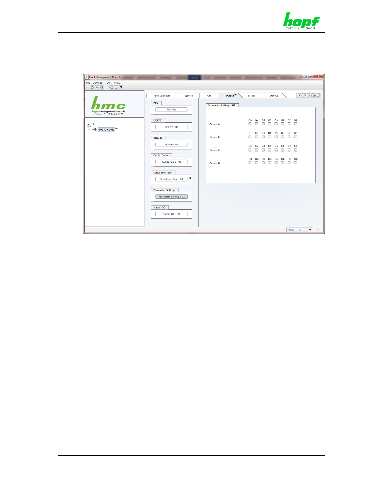
HMC (HOPF MANAGEMENT CONSOLE) SOFTWARE
62 / 76 8024GPS - GPS Sync Module - V02.00
hopf
Elektronik GmbH
Nottebohmstr. 41 • D-58511 Lüdenscheid • Tel.: +49 (0)2351 9386-86 • Fax: +49 (0)2351 9386-93 • Internet: http://www.hopf.com • E-Mail: [email protected]
3.6.4.6 Parameter Setting - optional hardware necessary
Panel for the additional configuration.
Page 63
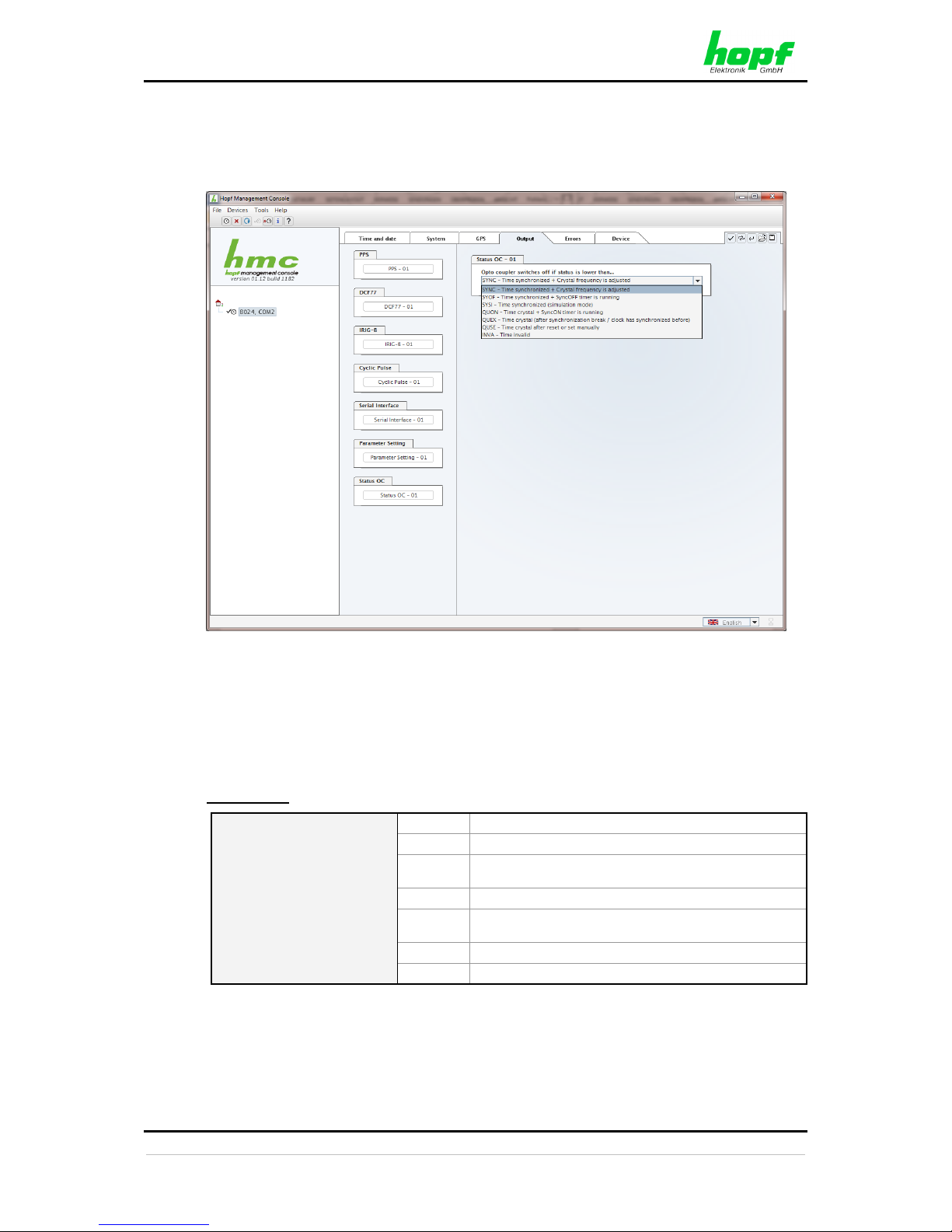
HMC (HOPF MANAGEMENT CONSOLE) SOFTWARE
8024GPS - GPS Sync Module - V02.00 63 / 76
hopf
Elektronik GmbH
Nottebohmstr. 41 • D-58511 Lüdenscheid • Tel.: +49 (0)2351 9386-86 • Fax: +49 (0)2351 9386-93 • Internet: http://www.hopf.com • E-Mail: [email protected]
3.6.4.7 Status OC
The output of the synchronization status via optical coupler (on the front panel of Sync Module
8024GPS) may be configured with this panel.
The synchronization status is represented from the bottom of the following table (INVA) up
with increasing quality.
Optical coupler:
• Selected status or better achieved – Optical coupler switched through
• Selected status not achieved – Optical coupler blocked
Value range
Optical Coupler Status
SYNC
Time synchronized + Quartz regulation started/running
SYOF
Time synchronized + SyncOFF running
SYSI
Time synchronized as simulation mode
(without actual GPS reception)
QUON
Quartz/Crystal time + SyncON running
QUEX
Quartz/Crystal time (in freewheel after synchronization
failure Board was already synchronized)
QUSE
Quartz/Crystal time after reset or manual setting
INVA
Invalid time
Page 64
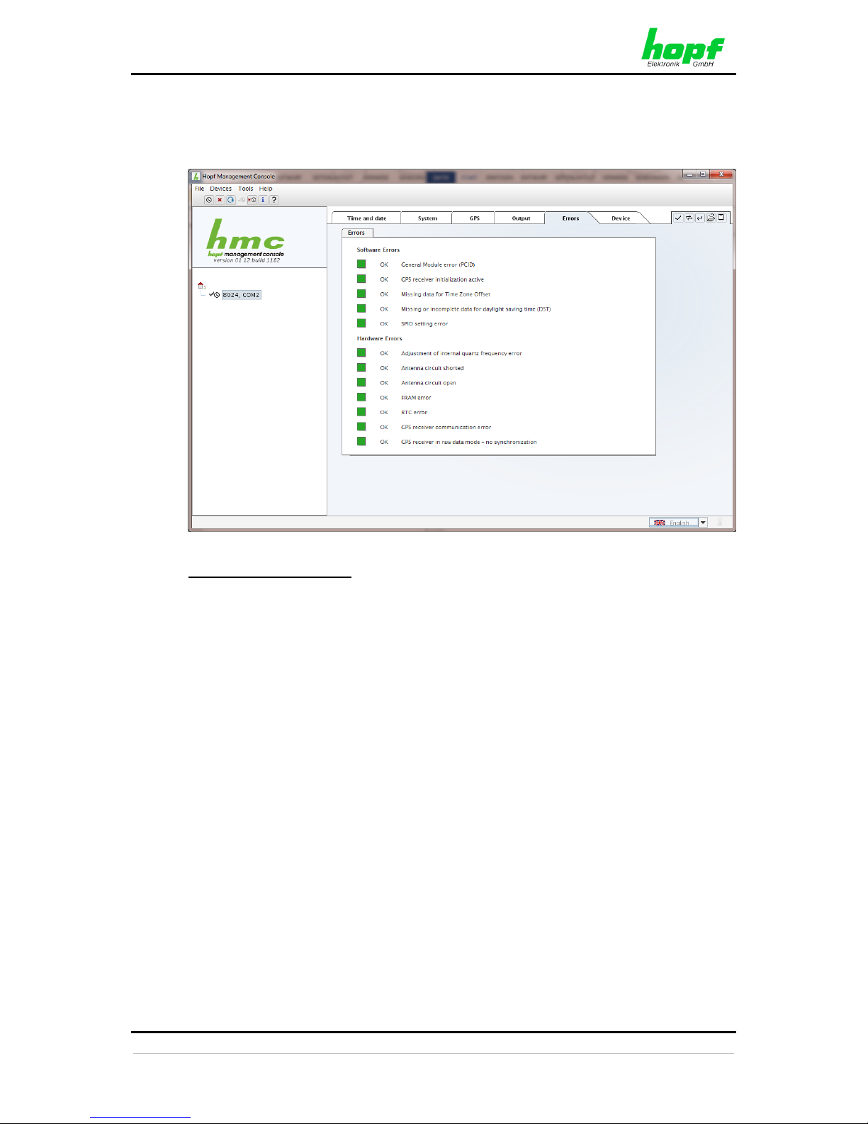
HMC (HOPF MANAGEMENT CONSOLE) SOFTWARE
64 / 76 8024GPS - GPS Sync Module - V02.00
hopf
Elektronik GmbH
Nottebohmstr. 41 • D-58511 Lüdenscheid • Tel.: +49 (0)2351 9386-86 • Fax: +49 (0)2351 9386-93 • Internet: http://www.hopf.com • E-Mail: [email protected]
3.6.5 Errors – Tab
This tab displays the current failure status of the Sync Module 8024GPS:
Overview Software Errors
• General Module error (PCID)
If this error occurs even after a Power down, the device is damaged.
• GPS receiver initialization active
This condition might last for max. 1 minute after particular actions.
• Missing data for Time Zone Offset
Difference time (Time Zone Offset) must be initially configured by the user.
Otherwise no synchronization of the Sync Source (here Module 8024GPS) is possible.
• Missing or incomplete data for daylight saving time (DST)
The switchover times for summer/winter time must be initially configured / disabled by
the user.
Otherwise no synchronization of the Sync Source (here Module 8024GPS) is possible.
• SPIO setting error
If this error occurs even after a voltage reset, the support team of company
hopf
needs to be contacted for further actions.
Page 65

HMC (HOPF MANAGEMENT CONSOLE) SOFTWARE
8024GPS - GPS Sync Module - V02.00 65 / 76
hopf
Elektronik GmbH
Nottebohmstr. 41 • D-58511 Lüdenscheid • Tel.: +49 (0)2351 9386-86 • Fax: +49 (0)2351 9386-93 • Internet: http://www.hopf.com • E-Mail: [email protected]
Overview Hardware Errors
• Adjustment of internal quartz frequency error
Problems with the internal quartz regulation of the Sync Source (here Module
8024GPS) have occurred. So the specified accuracy of the Sync Source cannot be
guaranteed anymore.
• Antenna circuit shorted
The Sync Source (here Module 8024GPS) has detected a short circuit in the antenna
system. The antenna system should be checked.
The error can be suppressed if e.g. an amplifier with its own power supply is used.
• Antenna circuit open
The Sync Source (here Module 8024GPS) has detected an open antenna input. The
antenna system should be checked.
• FRAM error
If this error occurs even after a voltage reset, the support team of company
hopf
needs to be contacted for further actions.
• RTC error
If this error occurs when time is configured or synchronized (synchronization status is
not INVA) and and even after a reset of the Sync Source (here Module 8024GPS) the
internal backup clock may be defective.
• GPS receiver communication error
If this error occurs even after a Power-Reset, the support team of company
hopf
needs to be contacted for further actions.
• GPS receiver in raw data mode – no synchronization
If this condition is indicated, the GPS receiver requires special data from the GPS
signal for which it needs up to 13 minutes signal reception of satellites. Only then the
Sync Source (here Module 8024GPS) can be synchronized.
This happens e.g. after resetting the Sync Source parameters to factory default
values.
Page 66
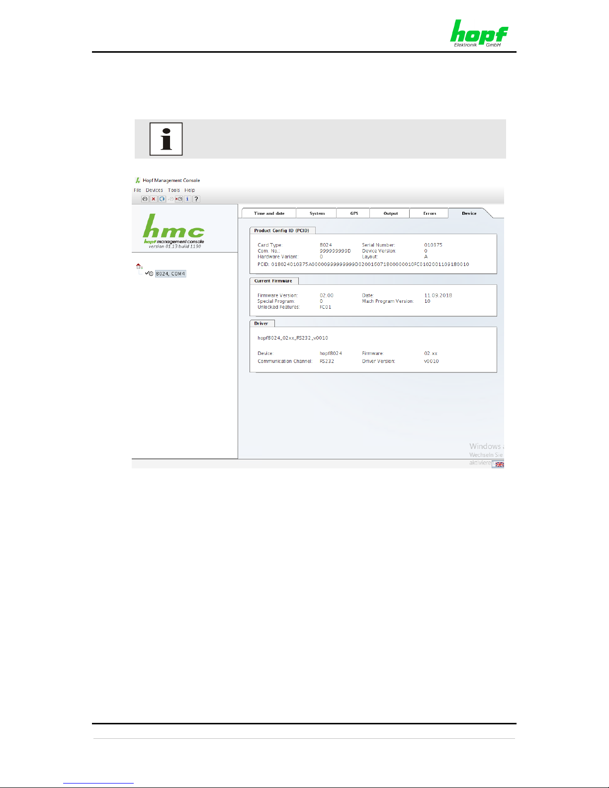
HMC (HOPF MANAGEMENT CONSOLE) SOFTWARE
66 / 76 8024GPS - GPS Sync Module - V02.00
hopf
Elektronik GmbH
Nottebohmstr. 41 • D-58511 Lüdenscheid • Tel.: +49 (0)2351 9386-86 • Fax: +49 (0)2351 9386-93 • Internet: http://www.hopf.com • E-Mail: [email protected]
3.6.6 Device – Tab
This tab indicates information about the hardware and software of the Module 8024GPS (Sync
Source).
These details might be provided for service and support purposes.
Page 67
FAULT ANALYSIS / TROUBLESHOOTING
8024GPS - GPS Sync Module - V02.00 67 / 76
hopf
Elektronik GmbH
Nottebohmstr. 41 • D-58511 Lüdenscheid • Tel.: +49 (0)2351 9386-86 • Fax: +49 (0)2351 9386-93 • Internet: http://www.hopf.com • E-Mail: [email protected]
4 Fault Analysis / Troubleshooting
Various indicators are available on the Sync Module 8024GPS for representation of the system
status and problem analysis. This status information can also be used to monitor the clock
system by means of a higher level management systems.
4.1 Fault Scenarios
This chapter describes various fault scenarios for initial analysis of the problem by the user. It
also provides assistance in describing the fault when contacting the
hopf
support team.
4.1.1 Complete Failure
Description
• The status LED’s on the front panel are off
Cause / Solution
• Equipment is switched off
• Power supply has failed
• Power supply unit is defective
4.1.2 No GPS Reception / No Synchronization
Description
• SYxx is not displayed on the status display of the time tab in the
hmc
software
• The status LED’s on the front panel do not signal any SYxx status
Cause / Solution
• System was not initialized correctly or initialization was incomplete
The following describes various effects and their possible causes in the case of a nonsynchronizing system:
Case 1:
Effect: No satellite appears on tab GPS of
hmc
software after first installation and
00 is displayed under In View.
Possible faults:
* The antenna cable is too long
* An incorrect type of cable was used for the antenna cable length
* The antenna cable is faulty
* The antenna cable is not connected
* The antenna is faulty
* The indirect lightning protector is faulty
Page 68
FAULT ANALYSIS / TROUBLESHOOTING
68 / 76 8024GPS - GPS Sync Module - V02.00
hopf
Elektronik GmbH
Nottebohmstr. 41 • D-58511 Lüdenscheid • Tel.: +49 (0)2351 9386-86 • Fax: +49 (0)2351 9386-93 • Internet: http://www.hopf.com • E-Mail: [email protected]
Case 2:
Effect: There are 7 satellites within the range of visibility (In View=07) but only a
maximum of 2 are displayed in the GPS tab. However, the values of these
satellites are 50 or higher.
Possible fault:
* The visibility range of the antenna to the sky is restricted.
Case 3:
Effect: 9 satellites in the range of visibility (In View=09), 6 satellites appear in the
GPS tab. The signal to noise ratios are all less than 30. The module does not
synchronize.
Possible faults:
* The cable is too long
* An incorrect type of cable was used for the length of the antenna equipment
* The BNC sockets are not mounted correctly
* The cable is kinked or broken
* The indirect lightning protector is faulty
* Faulty antenna
Case 4:
Effect: The module was working well previously but there has been no reception for
several days. There are 7 satellites in the range of visibility (In View=7).
However, no satellite is displayed.
Possible faults:
* The cable is damaged.
* There was excess voltage on the antenna equipment and the lightning
protection is damaged.
* The antenna is faulty.
* The GPS receiver on the Sync Module 8024GPS is faulty.
* A constructional change has had an effect on the antenna equipment (e.g.
shading of the antenna due to subsequent building work or the subsequent
laying of cables with high alternating fields in the close vicinity of the antenna
cable)
* Electronic devices with an interference effect on the GPS signal have been
put into operation in the vicinity of the GPS antenna equipment or receiver
(e.g. pager transmitter)
Further information on the subject of the GPS antenna equipment can be found in the
document titled "GPS Antenna Equipment".
Page 69
FAULT ANALYSIS / TROUBLESHOOTING
8024GPS - GPS Sync Module - V02.00 69 / 76
hopf
Elektronik GmbH
Nottebohmstr. 41 • D-58511 Lüdenscheid • Tel.: +49 (0)2351 9386-86 • Fax: +49 (0)2351 9386-93 • Internet: http://www.hopf.com • E-Mail: [email protected]
4.1.3 Incorrect Time Output
Description – Local Time
• Local time transmitted is at variance with the actual local time
Cause / Solution
• UTC/Local time offset not set or set incorrectly
• DST changeover points of time not set or set incorrectly
• Time was set manually, system running in quartz mode
• Time has drifted as the system has been running in quartz mode for a lengthy period
Description - UTC Time
• UTC time transmitted is at variance with the actual UTC time
Cause / Solution
• Time has drifted as the system has been running in quartz mode for a lengthy period
• Time was set manually, system running in quartz mode
Cause of incorrect UTC time when setting manually: incorrect local time entered (the
local time must always be entered when setting)
or the system was configured incorrectly (time zone offset, daylight saving time
changeover)
4.1.4 No DST changeover
Description
• "daylight saving time" (summer time) does not appear on the tab time and date of the
hmc
software.
• The "daylight saving time" (summer time) is not set under status in the output protocol.
Cause / Solution
• Changeover points of time not set or set incorrectly
• Output/display was configured for UTC and not local time
Page 70
FAULT ANALYSIS / TROUBLESHOOTING
70 / 76 8024GPS - GPS Sync Module - V02.00
hopf
Elektronik GmbH
Nottebohmstr. 41 • D-58511 Lüdenscheid • Tel.: +49 (0)2351 9386-86 • Fax: +49 (0)2351 9386-93 • Internet: http://www.hopf.com • E-Mail: [email protected]
4.2 Support from the
hopf
Company
Should the system show error indications other than those listed in Chapter 4.1 Fault
Scenarios, please contact the support team at
hopf
Elektronik GmbH with the exact
description of the fault and the following information:
• Serial number of the device
• Screenshot of the Module Info - tab and TIME - tab of the
hmc
software (if possible)
• Occurrence of the error: during commissioning or during operation
• Exact error description
• In the case of GPS reception/synchronization problems description of the antenna
equipment used:
o Components used (antenna, indirect lightning protector, etc.)
o Cable type used
o Total length of the antenna equipment
o Sequence of components and cable lengths between the components
o Antenna installation position (e.g. signal shading by building)
Please write to the following E-mail address with the above information:
Providing a detailed description of the error and the information listed above
avoids the need for additional clarification and leads to faster processing by
our support team.
Page 71
MAINTENANCE / CARE
8024GPS - GPS Sync Module - V02.00 71 / 76
hopf
Elektronik GmbH
Nottebohmstr. 41 • D-58511 Lüdenscheid • Tel.: +49 (0)2351 9386-86 • Fax: +49 (0)2351 9386-93 • Internet: http://www.hopf.com • E-Mail: [email protected]
5 Maintenance / Care
The module is generally maintenance-free. The following points should be noted if it is
necessary to clean the module/device.
The following must not be used to clean the receiver board:
• Fluids
• Cleaning agents containing solvents
• Cleaning agents containing acids
• Abrasive media
Do not use a wet cloth to clean the respective system.
There is the danger of an electric shock.
To clean the system use a cloth that is:
• Antistatic
• Soft
• Non-fabric
• Damp
Page 72
TECHNICAL DATA
72 / 76 8024GPS - GPS Sync Module - V02.00
hopf
Elektronik GmbH
Nottebohmstr. 41 • D-58511 Lüdenscheid • Tel.: +49 (0)2351 9386-86 • Fax: +49 (0)2351 9386-93 • Internet: http://www.hopf.com • E-Mail: [email protected]
6 Technical Data
General Data – Module only
Operation:
Via
hmc
software
Protection Class:
IP00
Voltage Supply:
5V DC ± 5% (device internal)
Power Consumption:
Typical approx. 120mA (max. 150mA)
Maintenance-free buffering of the
internal back-up clock:
more then 3 days
Weight:
approx. 0.2kg
Environmental Conditions
Temperature range:
Operation:
0°C to +55°C
Storage:
-20°C to +75°C
Humidity:
max. 95%, not condensed
Accuracy
Internal PPS pulse on GPS reception
(after 5min. continuous GPS reception):
Standard Quartz: < ± 30ns
VCTCXO: < ± 15ns
VCO control
of the internal quartz base
(after 5 min continuous GPS reception):
Standard Quartz: < ± 0.030ppm
VCTCXO: < ± 0.015ppm
Freewheel accuracy:
Standard Quartz: < ± 0.1ppm
after at least 5min. GPS reception/ T = +20° C
Drift for T = +20° C (constant):
- after 1h: 0.36msec.
- after 24h: 8.64msec.
VCTCXO: < ±0.02ppm
after at least 5min. GPS reception/ T = +20° C
Drift for T = +20° C (constant):
- after 1h: 0.72msec.
- after 24h: 1.73msec.
Internal back-up clock (RTC):
± 25ppm /
for T = +10° C to +50° C (constant)
Page 73
TECHNICAL DATA
8024GPS - GPS Sync Module - V02.00 73 / 76
hopf
Elektronik GmbH
Nottebohmstr. 41 • D-58511 Lüdenscheid • Tel.: +49 (0)2351 9386-86 • Fax: +49 (0)2351 9386-93 • Internet: http://www.hopf.com • E-Mail: [email protected]
Module - Signal Outputs
Full-duplex serial remote interface
(without handshake):
Via 9-pole SUB-D (male) connector in the
front panel (in RS232 level)
Status Optical Coupler:
Via 3-pole stackable screw terminal
Resistive circuit-breaking capacity:
max. 50mA / 80V DC
GPS Data
Receiver type:
22 channel phase tracking receiver, C/A code
Evaluation:
L1 frequency (1575.42MHz)
Sensitivity:
Tracking: -161dBm
Cold Start: -148dBm
Synchronization time
TTF (Time to First Fix):
• Warm start: < 1 Minuten
• Cold start: < 5 Minuten
• First initialization < 12,5 Minuten
(without valid leap second infomation)
Antenna connection:
• Via BNC socket
• For active antennas,
Ub = 5V DC / max. 70mA
• Antenna power fed via BNC socket of the module
Special production:
Modifications can be made to hardware and software in accordance with customer
specifications.
hopf
Elektronik GmbH reserves the right to modify hardware and software at
any time.
Page 74

FACTORY DEFAULT
74 / 76 8024GPS - GPS Sync Module - V02.00
hopf
Elektronik GmbH
Nottebohmstr. 41 • D-58511 Lüdenscheid • Tel.: +49 (0)2351 9386-86 • Fax: +49 (0)2351 9386-93 • Internet: http://www.hopf.com • E-Mail: [email protected]
7 Factory default
1. Deletion of the current leap second information
2. Time settings
• Difference time = Not initially set by the user
• Changeover points of time: = Not initially set by the user
• SyncON / SyncOFF timeout = 0000 / 0055 (minutes)
3. GPS settings
• Reception mode = Stationary-Mode (Position-fix)
4. Status optical coupler
• Synchronization status OK = SYNC
5. PPS - 01
• PPS duration = 10 msec
• Minimum sysnchronisation status
for a signal output = QUSE
• Value for a TimeOFF Timer = 0
• Outpu invertetd = deactivated
• Special Configuration = All deactivated
6. DCF77 - 01
• Time basis = Local
• Signal output for fault = 2Hz pulse
• Minimum sysnchronisation status
for a signal output = QUSE
• Value for a TimeOFF Timer = 0
• Outpu invertetd = deactivated
• Special Configuration = All deactivated
7. IRIG-B - 01
• IRIG-B - Format = B007/B127 (Time / Year / Second of day)
• Time basis = Local
• Minimum sysnchronisation status
for a signal output = QUSE
• Value for a TimeOFF Timer = 0
• Outpu invertetd = deactivated
• Special Configuration = All deactivated
8. Cyclic Pulse - 01
• Interval for cyclic pulse = 1 second
• Pulse duration = 50 msec
• Time basis = Local
• Minimum sysnchronisation status
for a signal output = QUSE
• Value for a TimeOFF Timer = 0
• Outpu invertetd = deactivated
• Special Configuration = All deactivated
Page 75
FACTORY DEFAULT
8024GPS - GPS Sync Module - V02.00 75 / 76
hopf
Elektronik GmbH
Nottebohmstr. 41 • D-58511 Lüdenscheid • Tel.: +49 (0)2351 9386-86 • Fax: +49 (0)2351 9386-93 • Internet: http://www.hopf.com • E-Mail: [email protected]
1. Serial Interface- 01
• Serial Interface Parameter = 9600 / 8 / n /1
• String Output =
hopf
binär String
• Time Base = UTC
• Output Scheme = Without second forerun /
immediate Control character
• Sendezeitpunkkt = Every Second
• Spezielle Einstellungen = All deactivated
2. Parameter Setting - 01
• Param A = All deactivated
• Param B = All deactivated
• Param C = All deactivated
• Param D = All deactivated
After the module has been reset to the DEFAULT values, the GPS receiver
requires after the initial setting of the difference time and the daylight saving
changeover times up to 13 minutes of continuous satellite reception to
determine the correct leap second information from the GPS data. The
Module 8024GPS can only synchronize after this has been done.
The following message appears on the error display during this period:
GPS-Receiver in raw data mode – no synchronization
Page 76

APPENDIX
76 / 76 8024GPS - GPS Sync Module - V02.00
hopf
Elektronik GmbH
Nottebohmstr. 41 • D-58511 Lüdenscheid • Tel.: +49 (0)2351 9386-86 • Fax: +49 (0)2351 9386-93 • Internet: http://www.hopf.com • E-Mail: [email protected]
8 Appendix
8.1 GPS (Global Positioning System)
Satellites circumnavigate the earth about twice per day at an altitude of approximately 20,000
km, on 6 different courses and at different angles.
The GPS system was developed based on 18 satellites with 3 replacement satellites. In order
to prevent short-term gaps in coverage the number was increased during development to 21
satellites with 3 replacement satellites. Above any point on the skyline, therefore, there are
always between 6 and 11 satellites visible. Highly precise atomic clocks are on board every
satellite (accuracy min. 1*10
-12
).
A base frequency of 10.23 MHz is taken from the atomic clocks. The two carrier frequencies
used, L1 and L2, are produced from this base frequency.
• Transmission frequency L1 = 154 * Base frequency = 1575.42 MHz
• Transmission frequency L2 = 120 * Base frequency = 1227.60 MHz
Each satellite sends all important navigation and system data by modulation on these two
carrier frequencies. In the public domain, data transmitted on L1 frequency may be evaluated.
The precise time can be calculated from this data by defining the position via the antenna.
The GPS antenna receives the signals of all satellites that are within sighting range above the
skyline and forwards them to the GPS receiver via a coaxial cable. 4 satellites are required for
continuous time evaluation.
Time calculation
The GPS receiver calculates world time UTC (Universal Coordinated Time) from GPS world
time (GPS-UTC) radiated by the satellite, by subtracting the leap seconds; at present (status:
March 2014) world time is running 16 seconds behind GPS-UTC time. The difference is not
constant and changes with the insertion of leap seconds.
The current standard time for the respective time zone is calculated by the addition of a time
offset to the UTC time. The time offset is the time difference between UTC time and the time
zone in which the clock system is situated, is set in the clock system by the user during
commissioning of the clock.
Any DST changeover that is due in the time zone is carried out via a switching function that is
to be configured in the clock system.
Advantages/Disadvantages GPS:
+
High accuracy
+
High security against interference
+
Worldwide application possible
+
High security against failure (terrestrial transmitters are often switched off when bad
weather conditions prevail at the transmission location)
+
High independent clock accuracy
–
Outdoor antenna required
–
Limited antenna cable lengths
 Loading...