

Page 1

Technical Description
GPS Satellite Controlled Clock
6875
Version 04.00 16.07.2008
Page 2
COMPANY INFO
Page 2 GPS Satellite Controlled Clock 6875 - Ver. 04.00
hopf Elektronik GmbH
Nottebohmstr. 41 58511 Lüdenscheid
Postfach 1847 58468 Lüdenscheid
Tel.: ++49 (0)2351 / 9386-86
Fax: ++49 (0)2351 / 9386-93
Internet: http://www.hopf.com
e-mail: [email protected]
Safety information
The safety regulations and technical data are important for the smooth running of the devices and
the protection of people and equipment. Strict compliance with these regulations is required. In case
of non-compliance with these regulations the guarantee and warranty claims for the device expire.
There is no liability for possible consequential damages.
Safety of the Devices
The production of this device follows the latest technological standards and safety regulations.
The device must not be assembled by anyone but trained personnel. Please make sure that all the
connected cables are laid and fixed properly. The device is to be run with the supply voltage stated
on the identification plate only.
Only trained personnel or specialists may operate the device.
Repair on opened devices must not be carried out by anyone but specially trained staff or by the
hopf Elektronik GmbH company.
If the maintenance work requires the opening of a device or if a fuse needs changing the device
must be separated from all voltage supplies.
If there are reasons to believe that the operational safety can no longer be guaranteed the device
must be taken out of service and labelled accordingly. The safety may be impaired when the device
does not operate properly or if it is obviously damaged.
Page 3

TABLE OF CONTENTS
CONTENTS Page
GPS Satellite Controlled Clock 6875 - Ver. 04.00 Page 3
1 General information 5
2 Quick installation 6
3 Hardware 7
3.1 Front panel components 7
3.2 Installation 8
3.2.1 Power supply 8
3.2.2 Connecting the antenna 8
3.2.3 Installation of the configuration software 8
3.3 Technical Data 9
4 Software 11
4.1 System requirements 11
4.2 Installation of the remote software 12
4.2.1 Uninstalling the remote software 12
4.2.2 Start programme 12
4.2.3 Trouble shooting 13
4.3 Functions of the configuration software 14
4.3.1 General 14
4.3.2 Selecting the serial interface 14
4.3.3 Changing the language 14
4.3.4 Information 15
4.3.5 Extras 15
4.3.6 Date & Time 17
4.3.7 Time Zone 18
4.3.8 Changeover time/changeover point 19
4.3.9 Position 20
4.3.10 Satellites 21
4.3.11 System Byte 22
4.3.12 Serial Parameters 24
4.3.13 Mode bytes 25
4.3.14 Optical coupler 27
4.3.15 Outputs 29
4.3.16 DCF77 Simulation 30
4.3.17 IRIG-B / IRIG Time Code 31
4.3.17.1 IRIG Time Code Structure and Timing-Diagram 32
4.3.17.2 Format categories IRIG-Bxxx according to IRIG Standard 200-04 33
4.3.17.3 IRIG IEEE 1344-1995 33
4.3.17.4 AFNOR NFS 87-500 33
4.3.18 Version / Reset 34
5 Data strings 35
5.1 General information on the serial data output of the 6875 board 35
5.2 Set-up of the standard (hopf6021) string 35
5.2.1 Status and day of the week nibble 36
5.2.2 Configuration for NTP (Network Time Protocol) 36
5.3 Data string: Standard (hopf6021) with year 2000 37
5.3.1 Status and day of the week nibble 38
5.4 Data string SINEC H1 39
5.4.1 Status in data string SINEC H1 40
Page 4

TABLE OF CONTENTS - CONTINUED
CONTENTS Page
Page 4 GPS Satellite Controlled Clock 6875 - Ver. 04.00
5.5 Data string T-String 41
5.6 Data string Master/Slave 42
5.6.1 Status in Data String Master/Slave 43
5.6.2 Setting 43
5.7 GPS2000 Data String 44
5.7.1 Time Accuracy in the GPS2000Data String 44
5.7.2 Configuration for GPS2000 Data String 45
5.8 Data String SAT 1703 Time String 46
5.8.1 Specified Settings 46
5.8.2 Data String Structure 46
5.8.3 Data String Example 47
5.9 SINEC H1 Extended 48
5.9.1 Data String Structure 48
5.9.2 Status 49
5.9.3 Example of a Transmitted Data String 49
6 Examples of connections 50
6.1 Assignment of the screw clips 50
6.1.1 Examples of connections for OC1-3 50
7 Dimensions of Snap-in Module Housing 52
8 Glossary und Abbreviations 52
Page 5

GENERAL INFORMATION
GPS Satellite Controlled Clock 6875 - Ver. 04.00 Page 5
1 General information
The 6875 radio-controlled clock is a universal GPS reception module with a highly accurate time
reference developed for controlling industrial processes. The 6875 snap-in module for 35mm
(DIN) track mounting is fitted with three PhotoMOS signal relays, an analogue and digital TTL
output and up to four independent serial interfaces.
The PhotoMOS signal relay outputs can be used, for example, for the SPS or measuring process control. Following output modes are available:
• DCF77 pulse
• System status (radio-controlled or quartz)
• Status of the power supply on/off
• Cyclical pulses
• Non-cyclical pulses (1 pulse per day at a defined time, 1 pulse per year at a defined
time and on a defined date)
The analogue output can be used to synchronize DCF77 or IRIG-B systems.
The serial interfaces COM0...COM3 are used for the output of different pulses and data strings.
Each interface can be configured with hopf remote software.
The 6875 snap-in module has further features:
• Potential-free antenna circuit
• All outputs potential-free
• All settings can be parametered via the COM0 serial interface
• COM1 interface can be switched from RS232 to RS422 via configuration software
• switchable analogue output IRIG-B / DCF77
The following versions of the system are available (indicated on the identification label):
• FG6875G00 (GPS 6875 snap-in module basic version) with
• 3 PhotoMOS pulse outputs
• serial interface COM0: RS232
• serial interface COM1: RS232/RS422
• simulation output for DCF77 antenna simulation or IRIG-B 12x (x=0..3)
• programming cable, remote software and technical documentation included
• FG6875G01 (6875 snap-in module) with
• GPS 6875 snap-in module basic version FG6875G00
• Serial interface COM2: optical output
• FG6875G02 (6875 snap-in module) with
• GPS 6875 snap-in module basic version FG6875G00
• Serial interface COM2: optical output
• Serial interface COM3: optical output
• FG6875G03 (6875 snap-in module) with
• GPS 6875 snap-in module basic version 6875
• Serial interface COM2: optical output
• Serial interface COM2: optical input
The configuration software on the CD supplied is available for the most common MS Windows,
Linux and Sun Solaris operating systems (for more details see 4.1).
Page 6

QUICK INSTALLATION
Page 6 GPS Satellite Controlled Clock 6875 - Ver. 04.00
2 Quick installation
Synchronization is accelerated by initialising the GPS 6875 satellite clock when first putting into
operation. It is not absolutely necessary to enter set-up values. However, without initialisation it
may be several hours before the first signals are received.
For quick installation it is necessary to set the following set-up values in the GPS 6875 satellite
controlled clock:
• Earth the device
• Connect the antenna
• Create communication between the PC and the remote-controlled clock
• Connect the power supply
• Install and start the remote software
• Set the current local time
• Ser the local time difference to UTC (local time - UTC)
• Set changeover dates
• Set the position data of the location; if this is not known then set an approximate value
or set everything to zero
• Activate the reset of the clock after the next minute change
• Wait approx. 10 minutes to 4 hours before synchronizing the radio-controlled clock
The individual menu items of the programme are explained on the following pages.
Page 7
HARDWARE
GPS Satellite Controlled Clock 6875 - Ver. 04.00 Page 7
3 Hardware
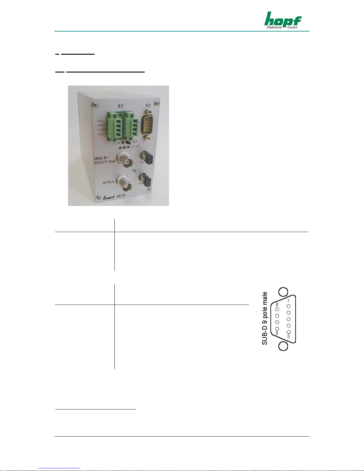
3.1 Front panel components
Connector X1
2 x 4 pole plug-in connectors (female) with codeable profile and threaded
flange (corresponding connector (male) is included)
+Vin Connection for positive potential of the power supply
–Vin Connection for negative potential of the power supply
+OC3, +OC2, +OC1 PhotoMOS signal relay connection for positive voltage potential (Drain)
−OC3, −OC2, −OC1
PhotoMOS signal relay connection for negative voltage potential (Source)
Connector X2
9 pole SUB-D connector
Pin No.: Function
1, 5 GND
4 Digital output, TTL
COM0 RS232
2 Receiving line
(RxD0)
3 Transmission line
(TxD0)
COM1 RS232 RS422
6 Transmission line
TxD1 +TxD1
1
7 Transmission line
-TxD1
2
8 Receiving line
RxD1 -RxD1
2
9 Receiving line
+RxD1
1
1
high active
2
low active
Page 8
HARDWARE
Page 8 GPS Satellite Controlled Clock 6875 - Ver. 04.00
LED / Key
Function
CLK green, indicates the synchronization status of the clock
C1-C3 yellow, indicates the switch status of the corresponding PhotoMOS signal
relay
DEF key (DEF)ault key for restoring the standard configuration
BNC connectors
IRIG-B /
DCF77-Out
analogue output for the output of the modulated IRIG-B or DCF77 signal
(BNC female connector)
GPS-In input for GPS antenna (BNC connector)
Option
optical interfaces COM2, COM3 (ST connection: bayonet)
FL 1 optical transmitter for serial interface COM2
FL 2 optical transmitter COM3 / optical receiver for serial interface COM2
3.2 Installation
3.2.1 Power supply
The power supply is connected via the 2 x 4-pole connectors, as supplied, with threaded flange,
connections +Vin und -Vin on the connecting unit X1. The system is provided with a voltage of
18...72 VDC..
The internal voltage supply of the 6875 snap-in module is potential-free. It must be earthed on
the rear side of the housing via the screw as labelled, in order to compensate the potential difference between the ground potential of the housing and the earth.
Please Note: ALTHOUGH THERE IS INTERNAL PROTECTION AGAINST WRONG POLING, ATTENTION
MUST BE PAID TO THE CORRECT VOTLAGE AND POLARITY WHEN CONNECTING THE
POWER. ONLY QUALIFIED STAFF SHOULD FIRST PUT THE EQUIPMENT INTO OPERATION.
3.2.2 Connecting the antenna
The antenna is connected via the hopf antenna cable to the GPS-In BNC connector (more information in the GPS appendix).
3.2.3 Installation of the configuration software
see 4.2.
Page 9

HARDWARE
GPS Satellite Controlled Clock 6875 - Ver. 04.00 Page 9
3.3 Technical Data
General
Snap-in module dimensions of
housing
width: 65 mm, height: 105 mm, depth: 130 mm
max. outer dimensions width: 65 mm, height: 105 mm, depth: 155 mm
Power supply
min. 18 to max. 72 VDC
Output isolation 500V DC
typical / max. performance 3,5 VA / 4 VA
Temperature range 0...+ 50 °C with improved free wheeling characteristics
0...+ 70 °C with restricted free wheeling characteristics
MTBF
> 295.000 hrs.
Accuracy (GPS Model)
PPS pulse (internal) ± 300 nsec
VCO control (internal time
base)
± 0,1 ppm, after approx. ½ hr. continuous GPS recep-
tion
Free wheeling characteristics
± 0,05 ppm, after VCO control at a constant tempera-
ture +10...+50 °C
PPS drift depending on
changes in power supply in free
wheeling status
± 0,0002 ppm/V
PPS drift depending on
changes in temperature in free
wheeling status
± 0,16 ppm/°C, at constant Uin=24V and temperature
radient of approx. 1,5°C/min
Accuracy (quartz model)
Free wheeling characteristics ± 0,5 ppm, after factory setting of VCO control at a con-
stant temperature of +20°C
Drift
max. ±4 ppm/Year
Backup Clock
Accuracy ± 25 ppm from +10°C to +50°C
Backup (maintenance free) min. 3 / typ. 10 / max. 15 days
Optical coupler
max. performance, capacity in
Ohms
60V DC / 200 mA
Switch on/off delay 130 / 70 µsec. at 10 mA switch mode power supply
Output isolation 500V DC
DCF77 pulse
output at COM1,COM2 (FL1),
COM3 (FL2), TTL (X2)
accuracy same as internal PPS pulse
signal level depending on output interface
DCF77 simulation output
output at BNC (IRIG-B / DCF77-Out)
accuracy same as internal PPS pulse
carrier signal frequency 77.5 kHz ± 25 ppm
signal level
3...5 mV
pp
at 50 Ohm
Page 10

HARDWARE
Page 10 GPS Satellite Controlled Clock 6875 - Ver. 04.00
Info: The IRIG-B Output is done by the IRIG Standard 200-04!
IRIG Time Code (digital)
output at COM1,COM2 (FL1),
COM3 (FL2), TTL (X2)
accuracy same as internal PPS pulse
signal level depending on output interface
IRIG Time Code Format IRIG-B - B002 / B003 / B006 / B007,
IEEE1344, AFNOR NFS 87-500
IRIG Time Code (analogue)
output at BNC (IRIG-B / DCF77-Out)
accuracy same as internal PPS pulse
carrier signal jitter (1kHz) ± 2 µsec
signal level ca. 2 V
pp
(± 10%) at 50 Ohm
ca. 2 V
pp
(± 10%) at 600 Ohm
modulation ratio 3 : 1
IRIG Time Code Format IRIG-B – B122 / B123 / B126 / B127,
IEEE1344, AFNOR NFS 87-500
Interfaces: COM0, COM1
asynchronous, without handshake
Baud rate 300 - 19.200 Baud
Stop bit 1 / 2 bit
Word length 7 / 8 bit
Parity no, even or odd
Line length The line lengths depend on the type of line and the
setting of the Baud rate.
Option:
optical interface, λ = 820 nm
Interfaces: COM2, COM3
asynchronous, without handshake, optical
Baud rate 300 - 19.200 Baud
Stop bit 1 / 2 bit
Word length 7 / 8 bit
Parity no, even or odd
Optical transmitter:
COM2 (FL 1), COM3 (FL 2)
Optical receiver:
COM2 (FL 1)
Connection: ST series (bayonet)
Wave length
λ = 820 nm
Cable types supported (multimode)
50/125 µm, 62.5/125 µm, 100/140 µm or
200 µm HCS ® fibre
GPS receiver
8 canal, C/A Code, code plus carrier tracking
Log-in sensitivity -134 dBm
Log-out sensitivity -143 dBm
Frequency range L1 = 1575,42 MHz
Recording time
Warm start < 1 min. (backup max. 3 days)
Cold start 30 min. - 4 hrs.
(1
st
installation without definition of position)
Accuracy ± 300 nsec
Temperature range 0...+ 60 °C
Additional components: see GPS accessories
Please Note: SUBJECT TO ERRORS AND TECHNICAL MODIFICATIONS
Page 11
SOFTWARE
GPS Satellite Controlled Clock 6875 - Ver. 04.00 Page 11
4 Software
4.1 System requirements
The hopf 6875 configuration software is for configuration of a hopf 6875 radio-controlled clock
via a serial interface. The serial interface cable included is connected between the computer (at
the free serial interface) and the radio-controlled clock (COM0).
Depending on the platform the following system requirements are necessary for the remote software and/or the installation programme:
Windows
• Windows 95, 98, ME, NT, 2000, XP
• min. 32 MB RAM (128 MB recommended)
• min. 40 MB free hard disk memory
• screen resolution min. 640x480 (1024x768 recommended)
Linux
• RedHat 7.1, SuSE 7.2 or Debian 2.2R3
• glibc 2.x
• libstdc++-libc6.1-1.so.2
• X-Windows
• min. 32 MB RAM (128 MB recommended)
• min. 110 MB free hard disk memory
• screen resolution min. 640x480 (1024x768 recommended)
Solaris SPARC
• Solaris 8
• X-Windows
• min. 32 MB RAM (128 MB recommended)
• min. 75 MB free hard disk memory
• screen resolution min. 640x480 (1024x768 recommended)
Solaris x86
• Solaris (x86) 8
• X-Windows
• min. 32 MB RAM (128 MB recommended)
• min. 75 MB free hard disk memory
• screen resolution min. 640x480 (1024x768 recommended)
Please Note: FOR PROBLEM-FREE EXECUTION THE INSTALLER AND/OR THE CONFIGURATION
SOFTWARE REQUIRE ADMINISTRATOR OR ROOT RIGHTS FOR THE CORRESPONDING INTERFACE DEVICE.
Page 12
SOFTWARE
Page 12 GPS Satellite Controlled Clock 6875 - Ver. 04.00
4.2 Installation of the remote software
To install the remote software the installation programme/script must be started. This requires a
graphic user interface:
Windows
6875_v01_03_Win32_install.exe
Linux
6875_v01_03_Linux_install.bin
Solaris SPARC
6875_v01_03_Solaris_SPARC_install.bin
Solaris x86
6875_v01_03_Solaris_x86_install.bin
Follow the instructions in the installation programme to complete the installation.
4.2.1 Uninstalling the remote software
Windows
The application can be uninstalled via system control:
• Start menu Ö Set-up Ö System control Ö Select software
• Select remote software and click add/remove Ö Uninstall-programme starts
• Follow the instructions in the uninstall-programme
Unix Platforms
The application can be removed via the uninstall-programme supplied (Uninstall6875) which is
found in the corresponding subdirectory UninstallerData
(e.g. /opt/Hopf/6875/UninstallerData/Uninstall6875).
4.2.2 Start programme
Windows
After installation has been completed in the chosen directory (e.g. C:\rogramme\Hopf\6875) the
configuration software can be started by selecting the appropriate link (e.g. Start Ö Programme
Ö Hopf Ö Hopf 6875).
Unix Platforms
After completing installation into the chosen directory (e.g. /opt/Hopf/6875) the configuration
software can be started via Startscript (Hopf6875) which can be found in the bin-directory (e.g.
/opt/Hopf/6875/bin/Hopf6875).
Please Note: SINCE THE VALUES SHOWN ARE CONSTANTLY UPDATED, DELAYED REACTION
TIMES IN THE INPUT FIELDS WITH MOUSE OR KEYBOARD ENTRIES ARE POSSIBLE
WITH LESS POWERFUL SYSTEMS.
Page 13

SOFTWARE
GPS Satellite Controlled Clock 6875 - Ver. 04.00 Page 13
4.2.3 Trouble shooting
• If there is an initialisation error when the configuration software is started then the serial
interface is either incorrectly configured or is being used by another programme.
• If a communication error arises during the execution of the configuration software, then
the radio- controlled clock is incorrectly connected or another instrument is connected to
the interface selected.
• If another programme is using the same serial interface as the configuration software
(e.g. an NTP service), then this must be ended to ensure that the configuration software
functions correctly.
• If the monitor resolution is low or some fonts are missing there may be slight distortion
in the script of the configuration software. This does not however affect the functions.
• If during installation a JAVA VM version is selected which is already installed, then care
must be taken that the minimum version is Java2 1.3. Usually we advise using or installing JAVA-Runtime as supplied.
• Information about possible errors specific to operating systems can be found in the corresponding readme-file as supplied.
If there are any questions or installation problems please contact the support team at Ruprecht
& Partner OEG under the e-mail address: [email protected]
Updated versions can be found on the website of Ruprecht & Partner OEG: http://www.rdcs.at/
Page 14
SOFTWARE
Page 14 GPS Satellite Controlled Clock 6875 - Ver. 04.00
4.3 Functions of the configuration software
4.3.1 General
The hopf 6875 configuration software is for convenient configuration of a hopf radio-controlled
clock 6875 via an RS232 interface. All the parameters of the radio-controlled clock can be displayed or set via a graphic user interface. These are divided into categories (e.g. time zone,
changeover time, serial parameters, etc.). Each of these categories is illustrated on a tab in the
upper section of the window.
A click of the mouse activates a tab – the window with the corresponding details is switched up.
This is divided into two areas: the current values and the values to be set. When a tab is selected, the current values of the radio-controlled clock are requested and displayed. In this case
the values to be set correspond to the current values and can be changed by clicking the corresponding arrow fields or by manual input.
Activating the button "SEND" transmits the values to be set to the radio-controlled clock. If an
error occurs a message is emitted, otherwise the current values are updated.
The software can be ended by activating the button "END".
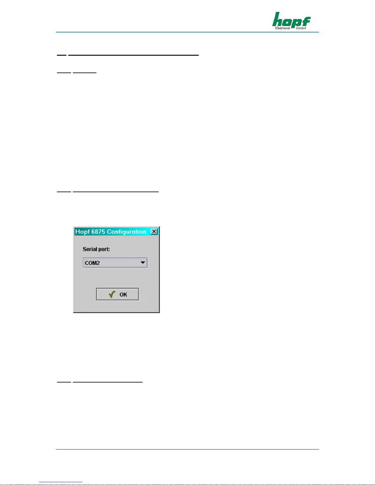
4.3.2 Selecting the serial interface
The serial interface to which the radio-controlled clock is connected can only be selected when
the programme is started.
Depending on the PC or operating system it may take some time to set up the selection window.
After selecting the appropriate interface the hopf 6875 configuration software will try to connect
to the radio-controlled clock. If no connection can be made a corresponding message will appear. In this case please check that the cable is correct and/or that the cable is connected to the
correct interfaces.
A new attempt to make a connection on the same interface can be made by selecting any other
tab. If this is to be tried on another interface then the programme must be ended and re-started.
4.3.3 Changing the language
The language used in the software can be changed during operation by selecting the desired
language in the selection menu on the left hand side of the window. This takes effect immediately after closing the selection window (perhaps with a slight delay, depending on the type of
PC).
Page 15
SOFTWARE
GPS Satellite Controlled Clock 6875 - Ver. 04.00 Page 15
4.3.4 Information
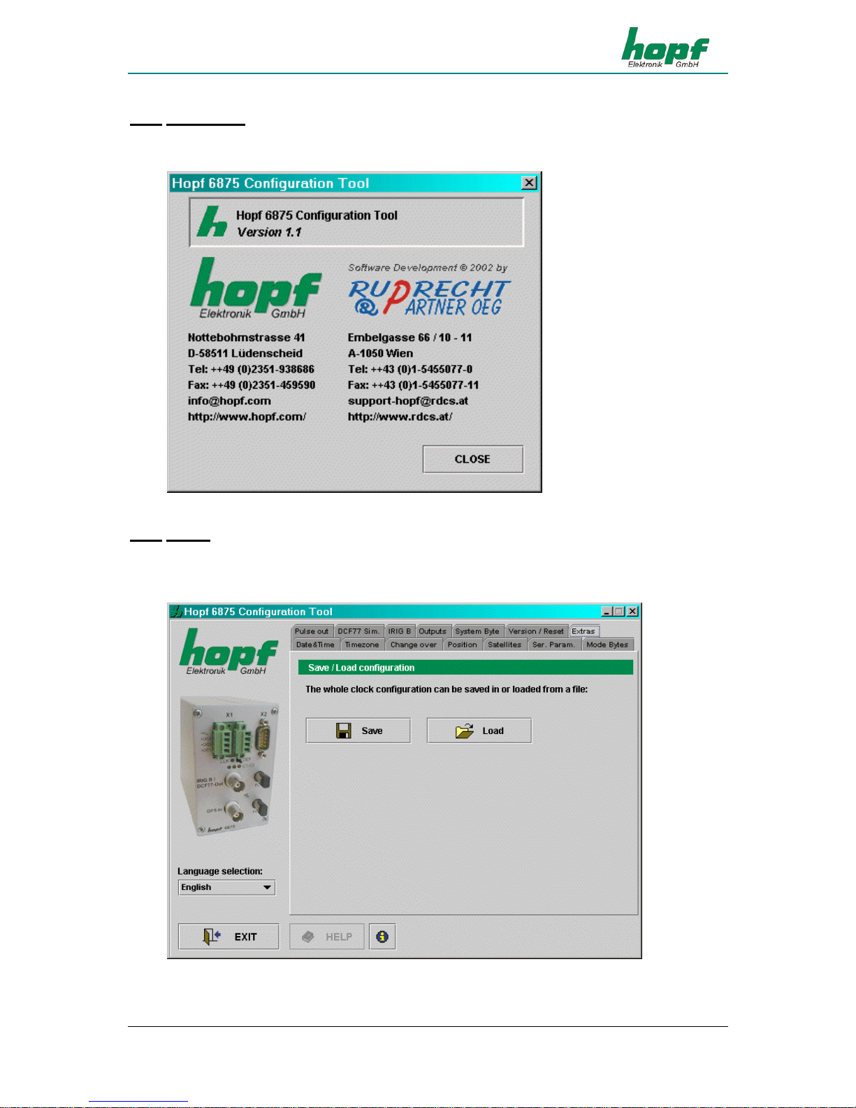
In this section information about the software or contacts can be found in the info dialogue
which is activated by clicking on the info button (on the right next to the button “help”).
4.3.5 Extras
This section makes it possible to save a complete configuration of a radio-controlled clock in a
configuration file (text file) or to load down from a configuration file and transmit to the radiocontrolled clock.
Page 16

SOFTWARE
Page 16 GPS Satellite Controlled Clock 6875 - Ver. 04.00
SAVE (IN A FILE)
Selecting the button "SAVE" opens a dialogue which enables selection of a target directory or
indication of a file name. After the target directory or a file name has been defined the current
configuration of the radio-controlled clock can be saved by selecting the button “SAVE“. As soon
as “SAVE” has finished, a confirmation dialogue appears which reports either success or error.
LAODING (FROM A FILE)
If a configuration is to be loaded which is already available or has already been saved then the
button “LOAD” should be clicked. A dialogue appears in which the file to be loaded is selected.
After selecting the file and confirming this with the button “OPEN” the following dialogue appears:
[LOAD DIALOGUE]
This dialogue shows in a well-structured form all the configuration data in the file which has
been loaded. The left column contains the definition of the value, the middle column the actual
value and the right column the status. If the status is “OK” (green), then this value is available –
if not, then the status of this value is “ERROR” (red). If at least one value has the status “ERROR”, the configuration cannot be transmitted to the radio-controlled clock. Otherwise the configuration shown can be transmitted to the radio-controlled clock by activating the button
“SEND”. This procedure can take some time and is confirmed after completion with a success
or error message. The dialogue can be ended by selecting the button “CLOSE”:
The button "HELP" is for activating online help – this contains all the information contained in
this document and additional general information about GPS.
Page 17
SOFTWARE
GPS Satellite Controlled Clock 6875 - Ver. 04.00 Page 17
4.3.6 Date & Time
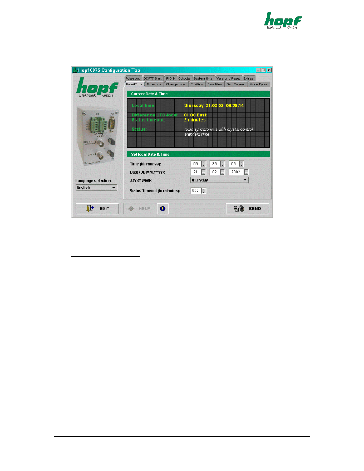
This section makes it possible to display and/or change values relating to date and time.
The following values are displayed or can be configured:
Day of the week, date, time:
Setting the day of the week, the date and the time is only necessary when commissioning the
radio-controlled clock. In this case the configuration software checks the plausibility of the time
and date values entered. Before transmission of the time to the radio-controlled clock the correct day of the week for the date entered is checked – if the day of the week entered differs from
that which is calculated then a corresponding message will appear.
Time difference:
Shows the actual time difference between local time and UTC in hours and minutes.
In this section the value is for information purposes only and can only be changed in the section
“Time Zone“ (4.3.7).
Status Timeout:
Shows the time delay in minutes until the resetting of the radio-controlled bit in the time status.
This value can be between 2 and 255 minutes.
Page 18
SOFTWARE
Page 18 GPS Satellite Controlled Clock 6875 - Ver. 04.00
Status:
Is made up of: synchronization status (e.g. quartz mode, radio-controlled mode, etc.) and actual
time status (e.g. daylight saving, standard time, announcement of changeover etc.). It is for in-
formation purposes only and cannot be changed.
Synchronization status of the radio-controlled clock:
• invalid time of day
• quartz mode
• radio-controlled mode (without quartz frequency control)
• radio-controlled mode (with high accuracy / with quartz frequency control)
Time status for local time of day:
• standard time
• daylight saving time
• announcement of changeover
• announcement of leap second
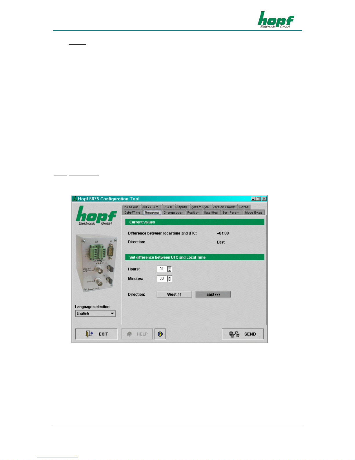
4.3.7 Time Zone
In this section the time zone for the location of the radio-controlled clock can be displayed and
adjusted. Setting the time difference is only necessary when commissioning.
The time difference (country- or location- specific time offset to UTC, difference between local
time and UTC) is made up of the following information:
Hour, minute and the information as to whether the location is west or east of the 0 meridian
(Greenwich).
The configuration software checks the plausibility of the values entered.
Example: West (-) 08:00 USA and Canada (Pacific Time)
East (+) 01:00 Germany
Page 19
SOFTWARE
GPS Satellite Controlled Clock 6875 - Ver. 04.00 Page 19
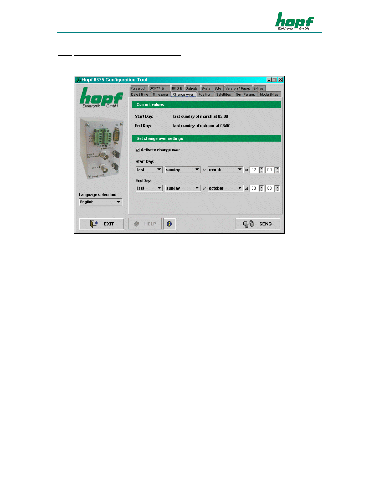
4.3.8 Changeover time/changeover point
In this section the daylight saving/standard and standard/daylight saving changeover times can
be displayed and changed.
In order to set the changeover times the changeover function must first be activated. If no
changeover is required this must be deactivated Ö time of day (local time) then runs in standard time status.
To set the changeover times the following information is required:
• first, second, third, fourth or last day of the week in the month
• day of the week
• month
• time in hours and minutes
Page 20
SOFTWARE
Page 20 GPS Satellite Controlled Clock 6875 - Ver. 04.00
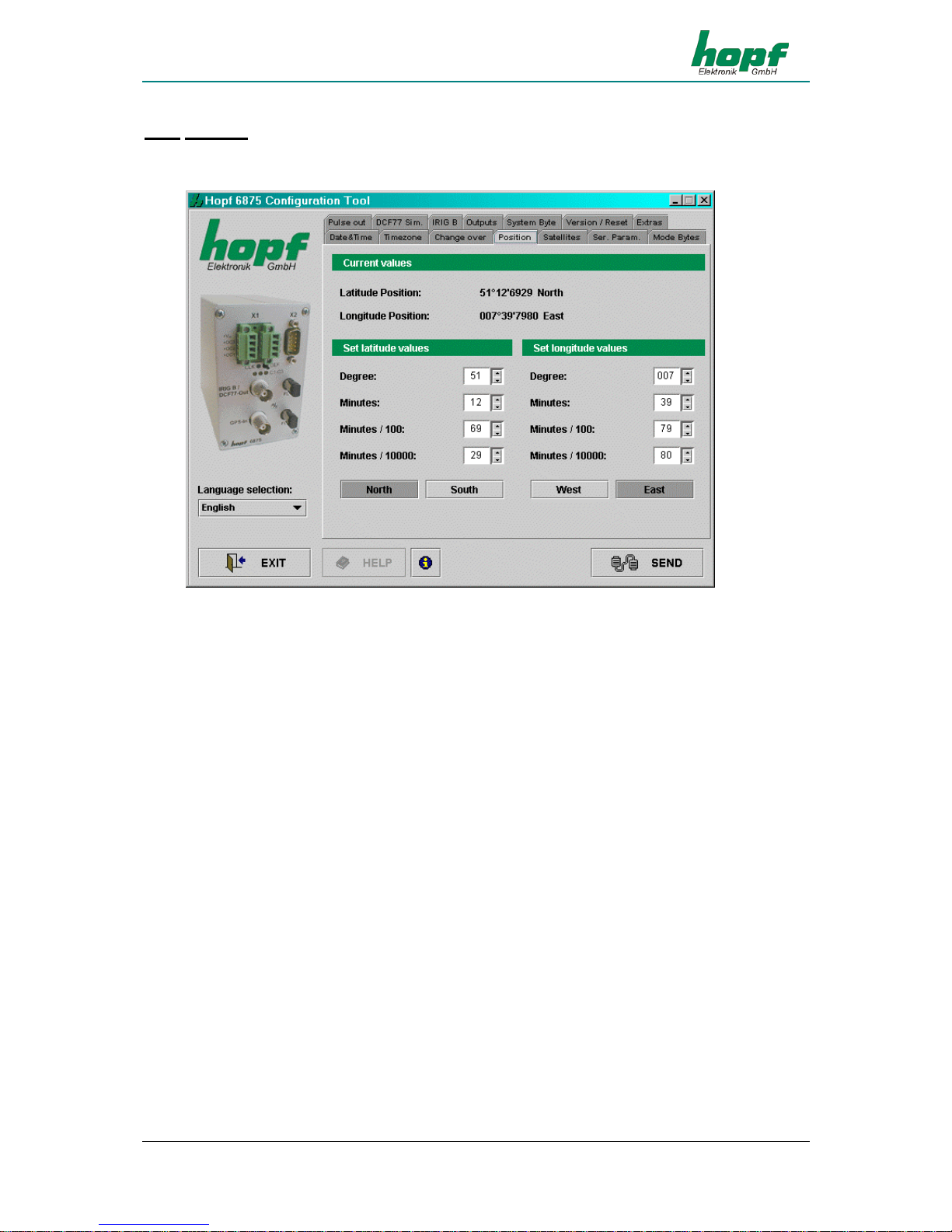
4.3.9 Position
This section enables the display and setting of the geographical position of the radio-controlled
clock.
Setting the approximate location position (if known) shortens the time required for first initialisation of the GPS receiver in the radio-controlled clock.
The entries of latitude and longitude are in degrees, minutes, 1/100 und 1/10000 minutes and
the following additional information concerning the geographical location:
Entry for latitude:
North = northern hemisphere
South = southern hemisphere Example: North 51°12,3651
Entry for longitude:
East = east of Greenwich meridian
West = west of Greenwich meridian Example: East 007°37,8426
For accelerated synchronization the GPS radio-controlled clock requires only the entry of the
approximate location. For the exact position shown in the above example the following entry
would suffice:
North 50°00,0000
East 007°00,0000
Page 21
SOFTWARE
GPS Satellite Controlled Clock 6875 - Ver. 04.00 Page 21
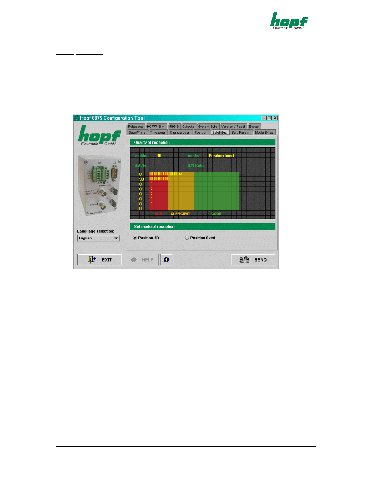
4.3.10 Satellites
This function enables display of the current satellite receiver quality as well as the configuration
of the GPS reception mode. The following values (updated periodically) are shown:
• number of satellites visible at the given time
• reception quality as S/N Ratio (signal to noise ratio ) for individual satellites
• evaluation mode for GPS satellite reception
The GPS reception mode can be set to 3D or Position fixed.
The accuracy of the time is determined by the accuracy of the calculation of the position of implementation of the clock. For this calculation reception from at least 4 satellites is necessary
(GPS reception mode 3D).
In the GPS reception mode Position fixed the accuracy depends considerably on the exact entry of the location of implementation. When entering the position up to ± 1 minute, the accuracy
of the second mark is already better than ± 20 µsec.
Position fixed has the advantage that the GPS radio-controlled clock can be synchronized with
one satellite only. The antenna can also be installed in locations where less than a quarter of
the sky is visible. In many cases it is possible to mount the antenna indoors near the window
(short cable lengths, no lightning protection).
If, in this mode, 4 satellites are available the evaluation jumps automatically to GPS reception
mode 3D and calculates the exact position.
Page 22
SOFTWARE
Page 22 GPS Satellite Controlled Clock 6875 - Ver. 04.00
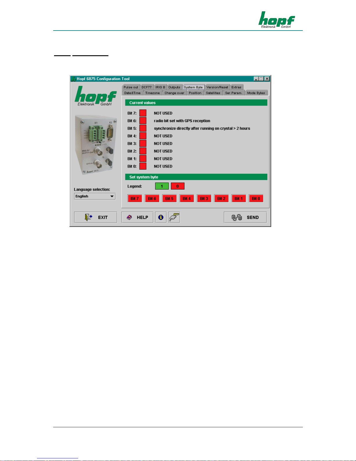
4.3.11 System Byte
This section permits the configuration of additional internal system functions. These are activated and deactivated by the setting and resetting of a bit.
Page 23
SOFTWARE
GPS Satellite Controlled Clock 6875 - Ver. 04.00 Page 23
Each bit has two possible statuses: IN (1) and OUT (0).
Default system byte configuration: Bit No.: 0 ... 7 = OUT (0).
Bit No.: IN (1) OUT (0)
7
unassigned unassigned
6
Permanent simulation of the time status
"radio synchronous ..." even without
valid GPS reception
Time status "radio synchronous ..."
only set in case of valid GPS reception
5
direct synchronisation of the second
and the millisecond with the exact GPS
second mark (*)
direct synchronisation of the second
and the millisecond with the exact GPS
second mark only after 2 hours (*)
4
unassigned unassigned
3
unassigned unassigned
2
unassigned unassigned
1
unassigned unassigned
0
unassigned unassigned
(*) Explanation referring to the function in system byte Bit-No.: 5:
• Bit-No.: 5 = OUT (0):
- Crystal operation < 2 hours Ö
The internal second and millisecond mark are slowly adjusted to the GPS second mark after the GPS resynchronisation (without leap).
- Crystal operation > 2 hours Ö
The internal second and millisecond mark are directly set to the GPS second
mark after the GPS resynchronisation (leap of the internal second mark).
• Bit-No.: 5 = IN (1):
- Crystal operation Ö
The internal second and millisecond mark are directly set to the GPS second
mark after the GPS resynchronisation (leap of the internal second mark).
- When "Output in crystal operation is locked" is activated, the signal output
of "IMP 1" and "IMP 2" (see chapter optical coupler) will be carried out at the
time status "radio synchronous with crystal regulation". Depending on the
accuracy demands for the application, the pulse output of the drifting pulses
(based on the fluctuant environmental conditions, like e.g. temperature) will be
locked or rather disconnected, if the GPS synchronisation fails.
Page 24
SOFTWARE
Page 24 GPS Satellite Controlled Clock 6875 - Ver. 04.00
4.3.12 Serial Parameters
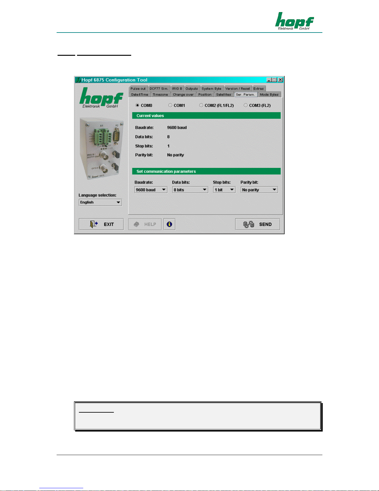
This section permits display and modification of the transmission parameters of the serial interfaces of the radio-controlled clock.
The selection of the interface to be configured is made in the upper part of the frame by clicking
the appropriate interface [COM0, COM1, COM2 (FL1/FL2) und COM3 (FL2)]. The current values for the selected interface are requested and displayed. These values can be changed by
selecting from the lists intended for this purpose.
The following serial parameters may be set:
Baud rate
input of the Baud rate: between 150, 300, 600, 1200, 2400, 4800, 9600 and
19200 Baud
Data bits
input of the word length: 8 or 7 Bit
Stoppbits
number of stop bits: 1 or 2
Parität
parity input: no, odd, even
If the serial interface COM0 of the clock has already been (previously) configured with different
parameters (status ex works <9600 baud, 8 data bits, 1 stop bit, no parity>), then the configuration data must be adjusted accordingly so that communication is possible between the configuration software and the clock. The transmission parameters for the serial interface via which the
configuration software is configured are stored in the configuration file <settings.conf>. This is
found in the installation directory (Windows platforms) or in the directory <Installation directory>/etc/ (UNIX-Platforms).
Please Note: BY ACTIVATING THE DEF KEY (PRESSS FOR AT LEAST 10 SECONDS) ON THE
FRONT PANEL OF THE CLOCK THE SERIAL PARAMETERS OF THE CLOCK ARE SET TO
<9600 BAUD, 8 DATA BITS, 1 STOP BIT, NO PARITY>.
Page 25
SOFTWARE
GPS Satellite Controlled Clock 6875 - Ver. 04.00 Page 25
In order to set the transmission parameters for the serial interface in <settings.conf> to the following values <9600 Baud, 8 data bits, 1 stop bit, no parity> the following entries are required:
baudrate=9600
databits=8
stopbits=1
parity=N
4.3.13 Mode bytes
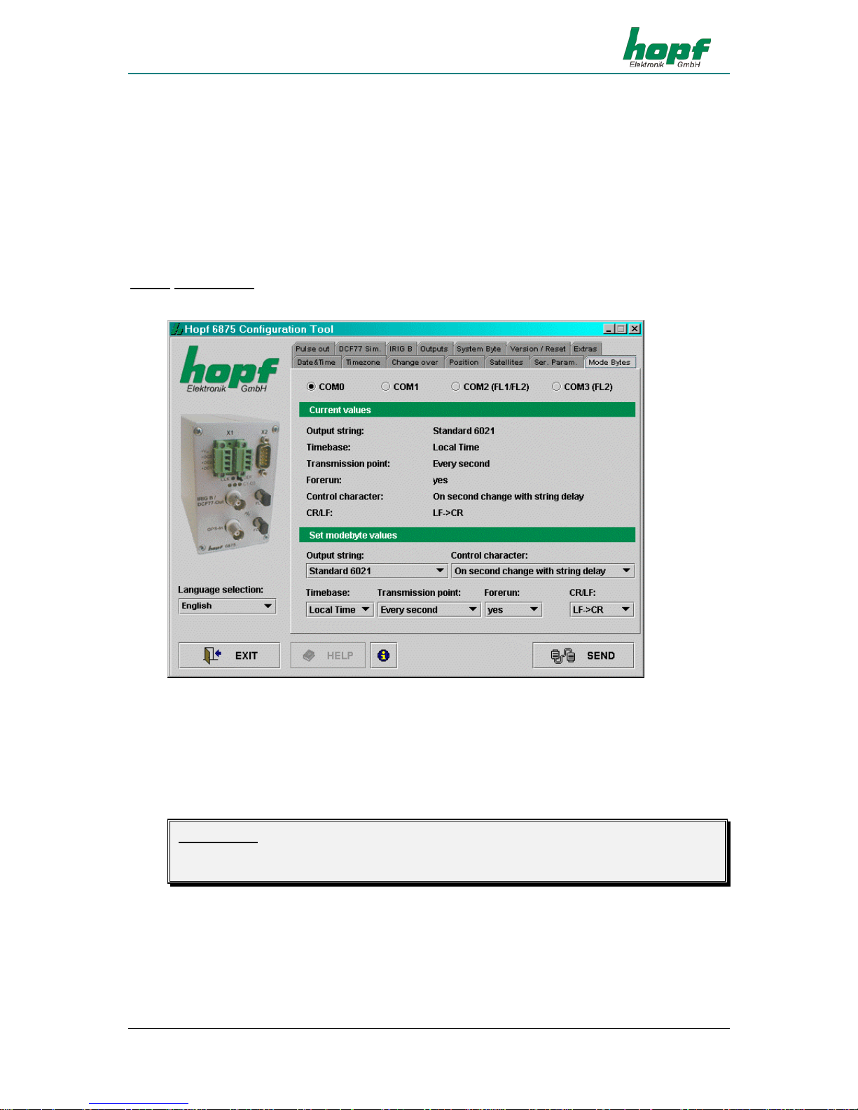
In this section the output strings of the serial interfaces are displayed and changed.
The serial interface to be configured is selected in 4.3.12.
There is a detailed description of the individual data strings in section 5.
The interface(s) designated for the output of the data strings as set must be indicated additionally in section 4.3.15.
Please Note: THE ENTRIES “C01 CUSTOM STRING” TO “C16 CUSTOM STRING“ IN THE SELEC-
TION “TRANSMISSION STRING“ ARE RESERVED FOR SPECIAL SOLUTIONS AND NORMALLY HAVE NO FUNCTION.
Page 26

SOFTWARE
Page 26 GPS Satellite Controlled Clock 6875 - Ver. 04.00
The following settings are possible:
Transmission
string
Type of data string to be emitted:
Standard 6021,
Standard 6021 with year 2000,
Master/Slave,
Siemens Sinec H1,
T-String,
GPS2000,
SAT 1703 Time String,
SINEC H1 Ext.
Control character
Output of ETX control character in the data string:
Standard (direct, no delay),
At the second change (no delay) or
At the second change (with delay)
Time basis
Time basis for the data string: Local time, UTC
Transmission
time
Output of the data string at the second change:
Each second
Each minute
Each hour
On request
Second forerun
Output of the data string with 1 second forerun: no, yes
CR / LF
Sequence for CR and LF: CR->LF, LF->CR
Page 27
SOFTWARE
GPS Satellite Controlled Clock 6875 - Ver. 04.00 Page 27
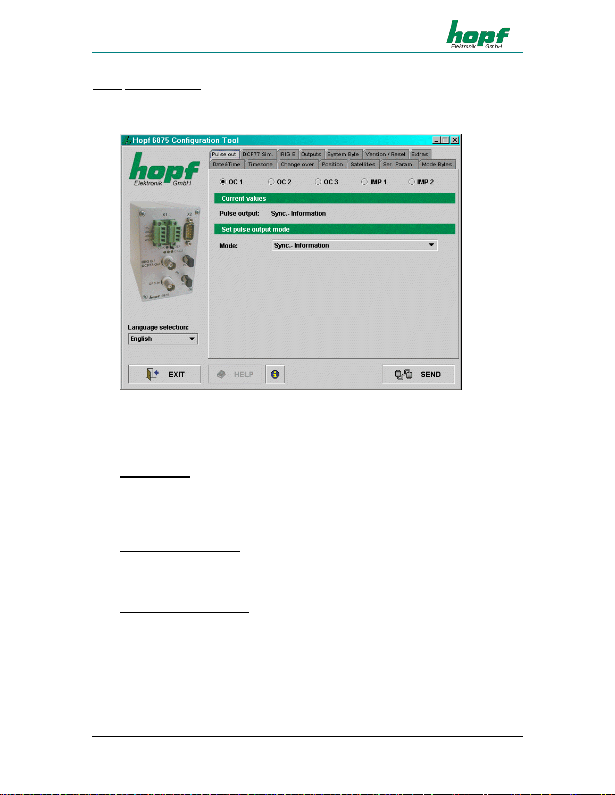
4.3.14 Optical coupler
This section enables the configuration of 3 PhotoMOS signal relay outputs and 2 additional
pulses. The selection of the signal relay outputs to be configured ("OK 1", "OK 2" and "OK 3")
and the pulses ("IMP 1" und "IMP 2") is made by clicking on the upper part of the frame.
The current values for the selected output or pulse are requested and displayed. Depending on
the "Modus" which has been set additional methods of configuration will appear or fade. The
following modes are supported:
DCF77 (Mode 0)
In this setting the DCF77 pulse will be emitted at the appropriate output. This setting is used, for
example, for the synchronization of further DCF77radio-controlled clocks with DCF77 pulse in-
put such as hopf 6850. If desired this signal can be inverted. The settings for the DCF77 pulse
are in the DCF77 menu and apply to all outputs emitting this.
Sync. Information (Mode 1)
In this setting the internal clock radio-control status is emitted at the corresponding output. If the
PhotoMOs signal relay is switched through then the clock is in radio-controlled status. The lapsing of the signals indicates quartz mode. The signal output can not be inverted.
System Information (Mode 2)
In this mode the corresponding output is switched through when the power supply is set. If there
is interference the signal lapses and hereby emits an alarm. The signal output cannot be inverted.
Page 28
SOFTWARE
Page 28 GPS Satellite Controlled Clock 6875 - Ver. 04.00
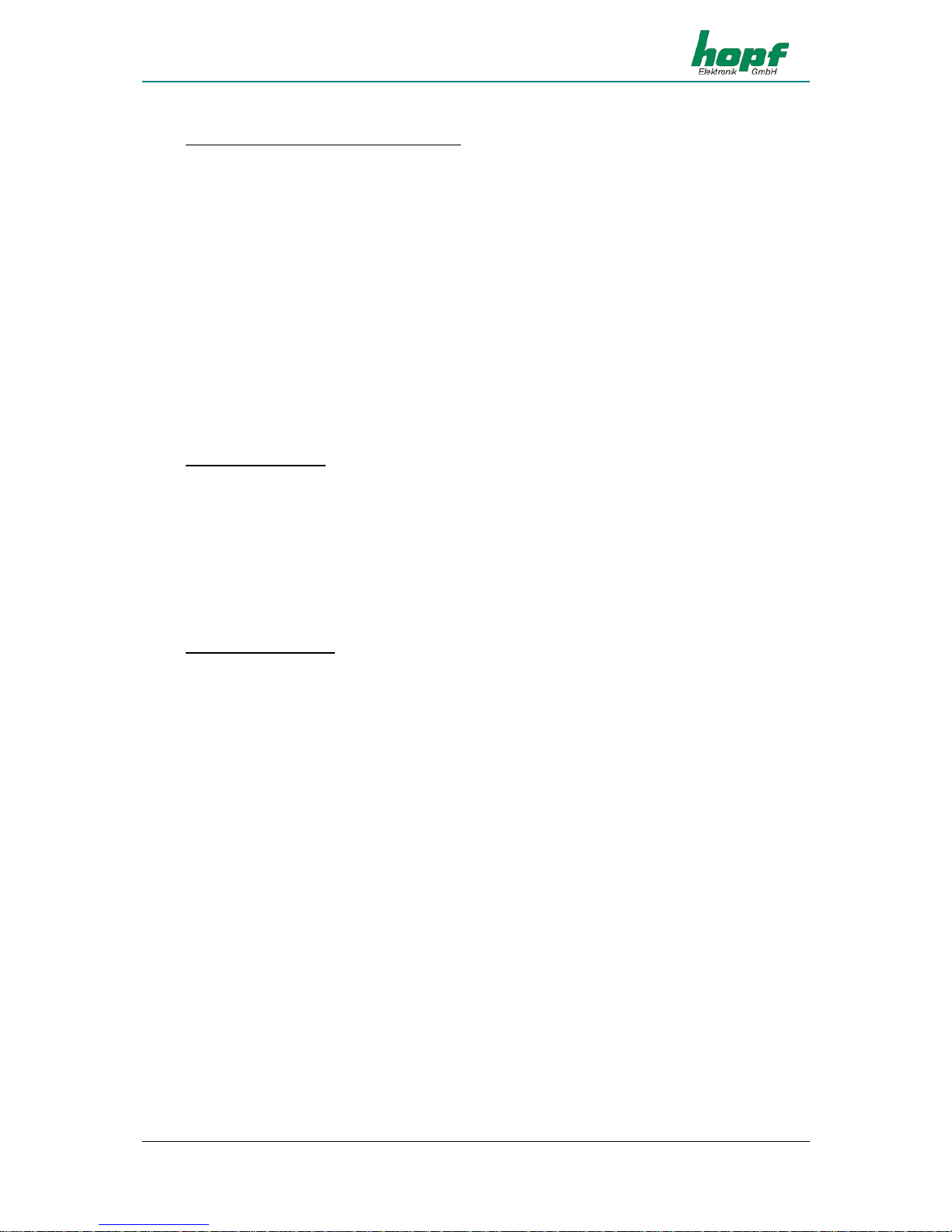
Cyclical output: within 24 hours (Mode 3)
In this mode cyclical pulses with an adjustable pulse width can be created on the corresponding
output. The following pulse intervals are possible:
every 1, 2, 3, 4, 6, 8, 12 hours
every 1, 2, 3, 4, 5, 6 , 10, 12, 15, 20, 30 minutes
every 1, 2, 3, 4, 5, 6 , 10, 12, 15, 20, 30 seconds
The output time of the pulse is fixed by clicking with the mouse on the appropriate arrow filed in
the input fields designated for this. A combination of hours, minutes and seconds is not allowed
and is prevented by the software.
The pulse length can be selected in the range of 10- 2550 msec in 10 msec steps. The Pulse
length should not exceed the cycle time, because then the output remains constantly switched
through.
It is possible to invert the signal output.
Daily pulse (Mode 4)
This mode creates a single pulse per day at the time entered at the output. The output time of
the pulse is fixed by clicking on the corresponding fields or by manual entry in the input fields
designated for this purpose.
The entries for day, month and year are deactivated.
The pulse length can be selected in the range of 10- 2550 msec in 10 msec steps.
It is possible to invert the signal output.
Single pulse (Mode 5)
This mode creates a single pulse per time and date at the output.
This mode creates a single pulse at a defined point in time. The output time of the pulse is fixed
by means of a mouse click on the corresponding arrow fields or by manual entry in the fields
designated for this.
The pulse length can be selected in the range of 10- 2550 msec in 10 msec steps. It is possi-
ble to invert the signal output.
In the settings Mode 2 and 3 it is of no benefit to invert the output, since, in the case of power
failure, false information would be passed on to the outputs. In the following paragraphs there is
an exact description of the individual modes.
By activating the checkbox "Disable output in quartz mode" it is possible, in the modes 4 and
3, to bind the pulses to the radio-controlled status, specially for IMP 1 and IMP 2. That means
that there is only a pulse output when the clock is in radio-controlled mode.
By deactivating the checkbox "Disable output in quartz mode" pulses are emitted in quartz
mode.
Configuration for an inverted output of the pulses IMP 1 and IMP 2 takes place in the section
“Outputs“ in 4.3.15.
The settings for the individual PhotoMos signal relays are each transmitted individually to the
radio-controlled clock.
Page 29
SOFTWARE
GPS Satellite Controlled Clock 6875 - Ver. 04.00 Page 29
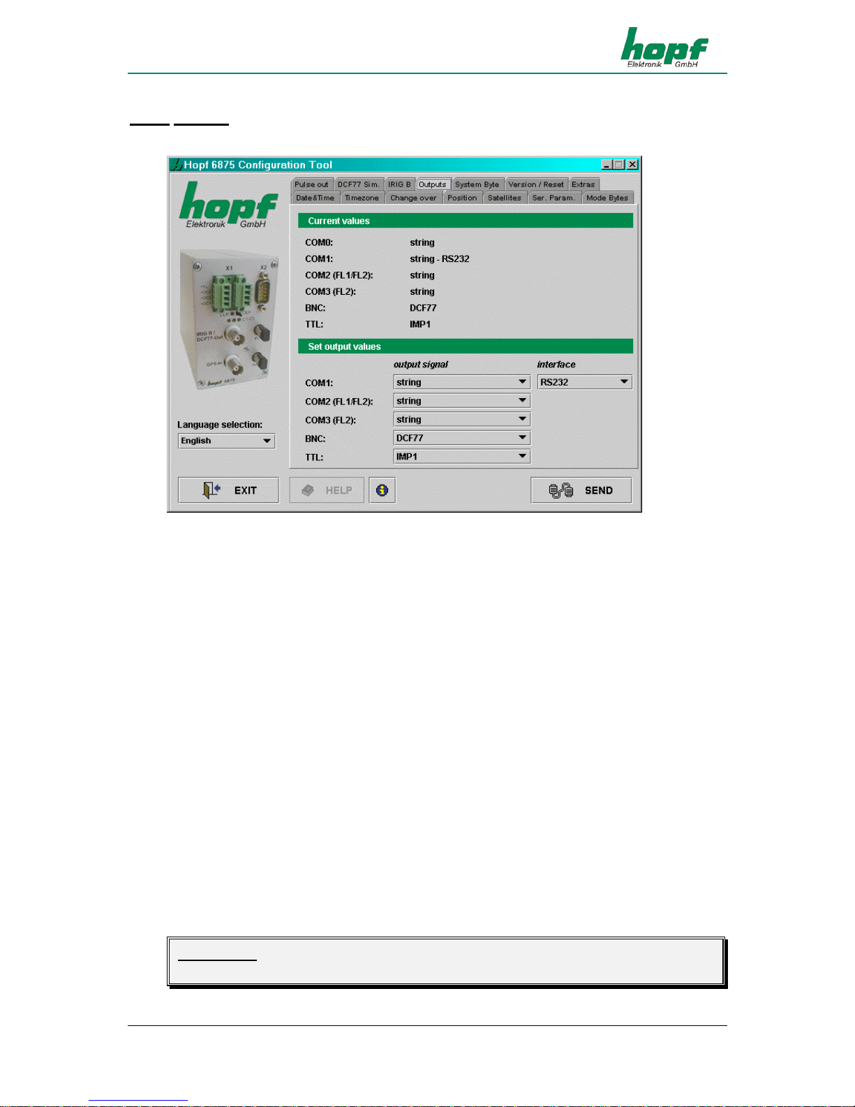
4.3.15 Outputs
This section permits the shunting of output signals to the outputs of the radio-controlled clock.
All the settings are made via selection lists.
Only the output of serial data strings is possible via the serial interface COM0. This is used
mainly for the configuration of the equipment or as a synchronization source.
The outputs: COM0, COM1, COM2 (FL1 / FL2) and COM3 (FL2) are serial interfaces, the output BNC refers to the analogue output IRIG-B / DCF77-Out and TTL describes the digital TTL
output on the connector X2.
Methods of configuring COM1 (serial interface COM1 in the radio-controlled clock):
• Output signal: data string, IMP1 (pulse1), IMP2 (pulse2), IRIG-B pulse
• Interface: RS232, RS422 full-duplex
• The output signals can also be emitted inversely
Methods of configuring COM2 and COM3 (optical serial interfaces):
• Output signal: data string, IMP1 (pulse1), IMP2 (pulse2), IRIG-B pulse
• The output signals can also be emitted inversely
Methods of configuring BNC:
• Output signal: DCF77 simulation or IRIG-B signal generation
Methods of configuring TTL (digital TTL output in the radio-controlled clock):
• Output signal: data string, IMP1 (pulse1), IMP2 (pulse2), IRIG-B pulse
• The output signals can also be emitted inversely.
Please Note: THE CONFIGURATION OF IMP1 (PULSE1) AND IMP2 (PULSE2) IS IN THE “OPTICAL
COUPLER“ MENU.
Page 30
SOFTWARE
Page 30 GPS Satellite Controlled Clock 6875 - Ver. 04.00
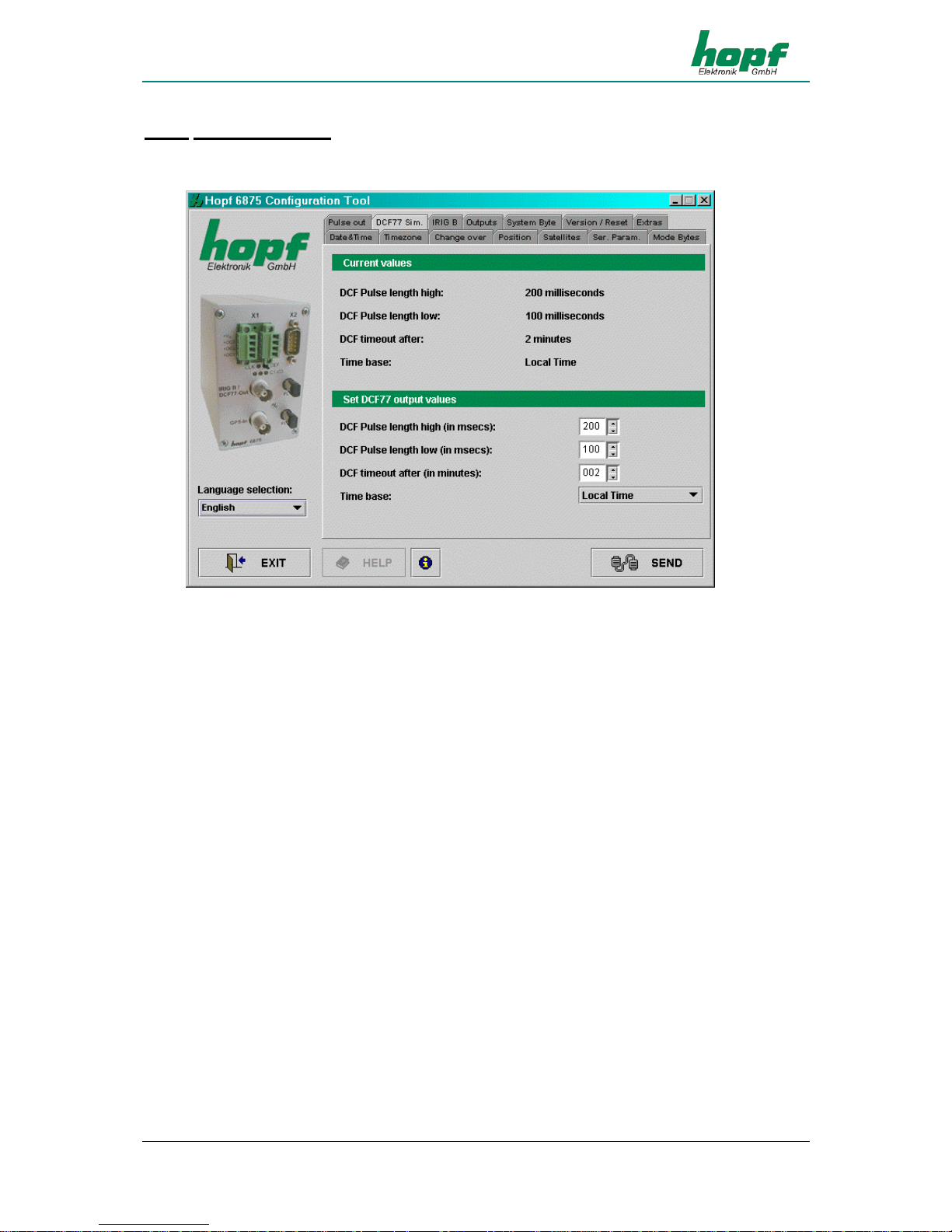
4.3.16 DCF77 Simulation
In this section settings can be made for the DCF77 simulation and the DCF77 pulse. These are
global settings and are valid for all outputs which emit a DCF77 simulation or DCF77 pulse.
The outputs at which a DCF77 pulse is emitted can be indicated in 4.3.15.
The following entries are required for configuration:
• Pulse length Highbit in the range 140...240 msec (Standard: 200 msec)
• Pulse length Lowbit in the range 70...130 msec (Standard: 100 msec)
• Delay for DCF77 switch-off in the range 2...255 minutes (at 255 Ö
∞)
• Time basis: local time or UTC
The pulse lengths and the switch-off delays are determined by mouse click on the corresponding input fields or by manual entry, the time basis is entered via the selection list.
The value "DCF77 timeout after" indicates the delay time in minutes for the output of the
DCF77 simulation or the DCF77 pulse when changing to quartz mode. If this value is set at 255
the DCF77 simulation and/or DCF77 pulse will be emitted permanently.
Page 31

SOFTWARE
GPS Satellite Controlled Clock 6875 - Ver. 04.00 Page 31
4.3.17 IRIG-B / IRIG Time Code
In this section the settings for the IRIG Time Code signal generation (analogue) are made.
These are global settings and are valid for the output of the analogous amplitude modulated
signal (e.g. IRIG-B B12x) as well as for the digital pulse width modulated signal (e.g. IRIG-B
B00x).
The 'analogue' IRIG Time Code is given out at the BNC-connector (IRIG-B). The outputs for
IRIG Time Code (digital) can be configured as described in chapter 4.3.15.
IRIG Time Code Formats
The following formats of IRIG Time Code are available:
o IRIG-B - B002/B122 (time)
o IRIG-B - B003/B123 (time, seconds of day)
o IRIG-B - B006/B126 (time, year)
o IRIG-B - B007/B127 (time, year, seconds of day)
o IEEE1344
o AFNOR NFS 87-500
Info: The IRIG-B output is done by the IRIG Standard 200-04.
Time Base for IRIG Time Code
For special applications the time basis transmitted in the IRIG Time Code can be configured.
o Local Time
o UTC Time
Timeout for delayed Output Break
This value acts as bypass for the reception failure for the output break of the IRIG Time Code
referring to delicate reception conditions.
With regard to a reception failure of the sync. source (here GPS) the turning off of the IRIG-B
signal is delayed by the adjusted figure.
The value can be set between 002 and 255 minutes.
Page 32
SOFTWARE
Page 32 GPS Satellite Controlled Clock 6875 - Ver. 04.00
4.3.17.1 IRIG Time Code Structure and Timing-Diagram
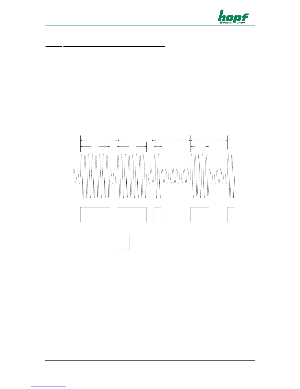
The IRIG format consists of one time code with 74 bits and has a repeatability rate of one second. The bit frame is 10 msec. The rating of a bit is displayed by a pulse width modulation and
is shown in multiples of a millisecond.
With analogue output the positive zero cycle of a sinus oscillation (carrier frequency 1000Hz) is
modulated with the rising edge of the IRIG signal. The rate of modulation for the signal information of H/L level should be between 3:1 and 6:1. The Din-Rail Module 6870 distributes a modulation of 3:1.
To synchronize to the beginning of a second a neutral logic status is required which is called the
identifier.
Logic 0 = 2 msec H-level
Logic 1 = 5 msec H-level
Identifier = 8 msec H-level
low
high
PPS
IRIG-B
digital
IRIG-B
analog
2msec
5msec
reference bit
position identifier
8ms 8ms
The 74 time code bits are divided into
30 bits for the BCD value of seconds, minutes, hours and the current day of year
27 bits for the input of control information
17 bits for the binary value of the current seconds of day
100 bit frames can be transmitted in one second. Unused bit frames are filled with a logical
zero.
Page 33
SOFTWARE
GPS Satellite Controlled Clock 6875 - Ver. 04.00 Page 33
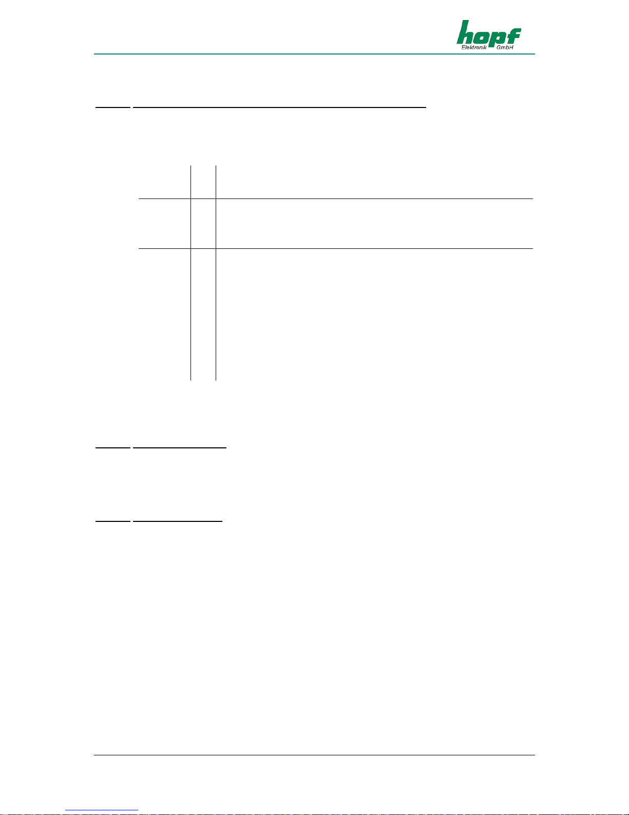
4.3.17.2
Format categories IRIG-Bxxx according to IRIG Standard 200-04
Signal output can be digital or analogue and also with different data content. The variations are
indicated by attaching a three-digit combination of figures.
The figures have the following meaning:
Figure 1
0 = digital output
1 = analogue output via carrier
Figure 2
0 = no carrier
1 = carrier 100 Hz
2 = carrier 1000 Hz
Figure 3
0 = time, second of day, control information
1 = time, control information
2 = time
3 = time, second of day
4 = time, year, second of day, control information
5 = time, year, control information
6 = time, year
7 = time, year, second of day
e.g. IRIG-B123 = analogue output, carrier 1000 Hz,
= data content time information and binary seconds of day
4.3.17.3 IRIG IEEE 1344-1995
This IRIG standard is based on IRIG Standard 200-89. Fixed data such as year, time offset etc.
are assigned to the 27 bits of the control information field.
The IRIG Standard 200-89 is contained as subset in the IEEE1344.
4.3.17.4
AFNOR NFS 87-500
The AFNOR NFS 87-500 Code is similar to the IRIG Time Code Standard. It has been laid
down by the French institute for standards and is based on the IRIG Standard 200-4.
The IRIG-B Standard 200-89 is contained as subset in the AFNOR NFS 87-500.
Page 34
SOFTWARE
Page 34 GPS Satellite Controlled Clock 6875 - Ver. 04.00
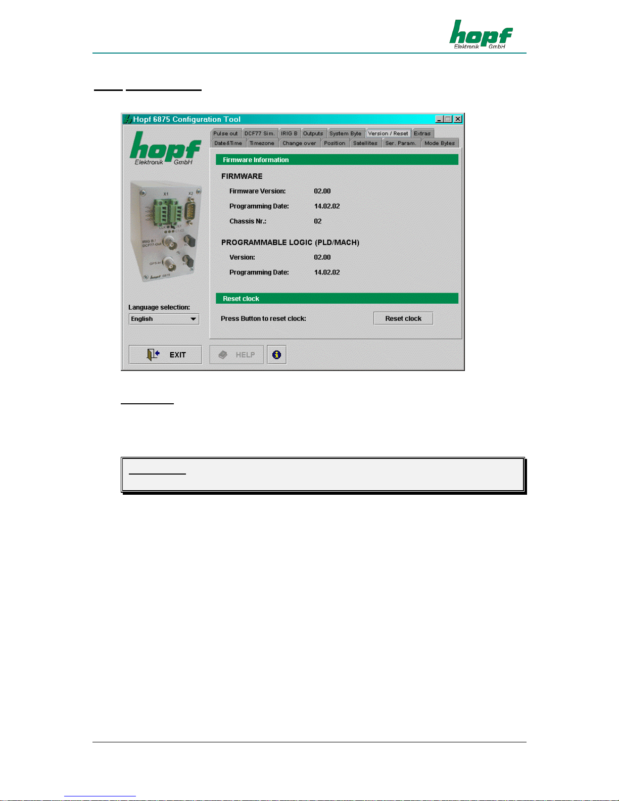
4.3.18 Version / Reset
Firmware information is shown in this section.
Reset clock
A restart of the clock is initiated by this function. The function does not change any of the settings made previously, in contrast to the DEF key in the front panel. A reset is necessary after
inputs are completed in order to accelerate the first synchronization.
Please Note: WHEN CHANGES HAVE BEEN MADE ON THE RADIO-CONTROLLED CLOCK IT IS AD-
VISABLE TO WAIT FOR THE MINUTE CHANGE BEFORE SETTING UP RESET.
Page 35

DATA STRINGS
GPS Satellite Controlled Clock 6875 - Ver. 04.00 Page 35
5 Data strings
5.1 General information on the serial data output of the 6875 board
When setting ETX to the second change a transmission gap occurs, depending on the Baud
rate, of up to 970 msec. Please pay attention to this when programming timeout on the receiving side.
On all data strings the output of control character CR and LF can be exchanged with mode-
byte.
The transmitted data string are compatible with the data strings of the following hopf clocks:
• Board 6020/6021 standard with control character
• Board 7200/7201 standard with control character
• Board 7220/7221 standard with control character
• Board 7240/7245 standard with control character
• Board 6840/6841 standard with control character
• System 4465 standard with control character
• System 6870 standard with control character
5.2 Set-up of the standard (hopf6021) string
character no.: Meaning Hex
1 STX (Start of Text) $02
2 status (internal status of the clock) $30-39, $41-46
3 day of the week (1=Monday ... 7=Sunday) $31-37
bit 3 in the day of the week is set to 1 with UTC
4 tens hours $30-32
5 unit hours $30-39
6 tens minutes $30-35
7 unit minutes $30-39
8 tens seconds $30-36
9 unit seconds $30-39
10 tens days $30-33
11 unit days $30-39
12 tens months $30-31
13 unit months $30-39
14 tens years $30-39
15 unit years $30-39
16 LF (Line Feed) $0A
17 CR (Carriage Return) $0D
18 ETX (End of Text) $03
Page 36
DATA STRINGS
Page 36 GPS Satellite Controlled Clock 6875 - Ver. 04.00
5.2.1 Status and day of the week nibble
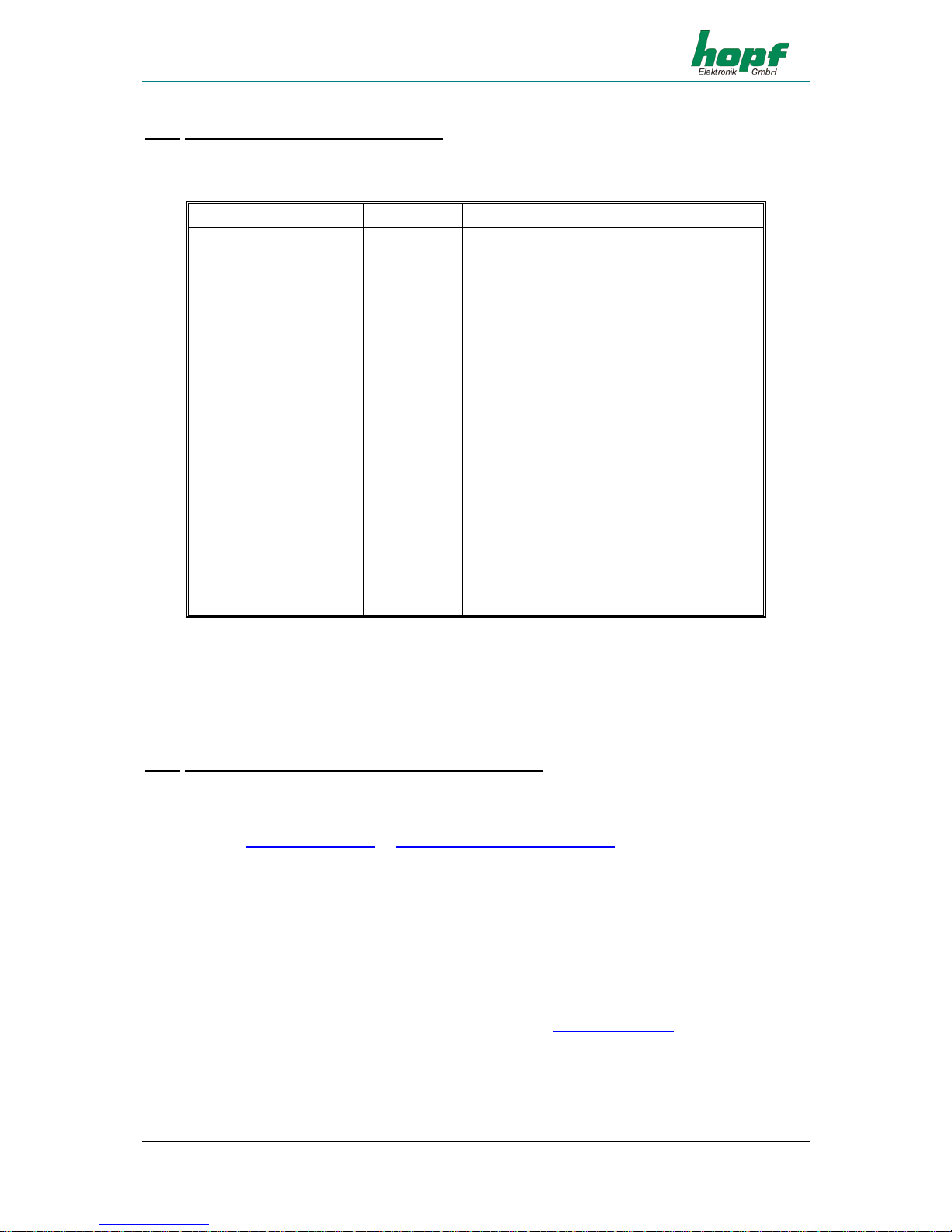
The second and third ASCII character in the string contain the status and the day of the week.
The evaluation of the status is binary. Set-up of the characters:
b3 b2 b1 b0
Meaning
Status nibble:
x x x 0 No announcement hour
x x x 1 Announcement (DST-ST-DST)
x x 0 x Standard time (ST)
x x 1 x Daylight saving time (DST)
0 0 x x Time/date invalid
0 1 x x Quartz mode
1 0 x x Radio-controlled mode
1 1 x x Radio-controlled mode (high accuracy)
Day of the week nibble:
0 x x x CEDST/CET
1 x x x UTC time
x 0 0 1 Monday
x 0 1 0 Tuesday
x 0 1 1 Wednesday
x 1 0 0 Thursday
x 1 0 1 Friday
x 1 1 0 Saturday
x 1 1 1 Sunday
Example: (STX)E3123456170496(LF)(CR)(ETX)
Radio-controlled mode (high accuracy)), daylight saving time, no announcement
It is Wednesday 17.04.96 - 12:34:56 hrs.
( ) – ASCII control characters e.g. (STX)
5.2.2 Configuration for NTP (Network Time Protocol)
NTP or also xNTP is a programme package for synchronizing different computer and operating
systems with network support. It is the standard for Internet protocol TCP/IP (RFC-1305).
Source code and documentation are available as freeware in the Internet under the following
address: http://www.ntp.org
or http://www.eecis.udel.edu/~ntp/
NTP supports the hopf protocol as described in section 5.2. The following settings are required
in the clock board:
Transmission parameters: 9600 Baud, 8 data bits, no parity, 1 stop bit
Transmission mode: Standard 6021 (hopf6021, time and date), outputevery sec-
ond, time basis: UTC, with second forerun, with ETX at the
second change with control characters (STX...ETX), LF->CR
There are already pre-configured NTP packages for hopf radio-controlled clocks with serial interface. On the homepage of Ruprecht&Partner (OEG) (http://www.rdcs.at/
) these are available
for downloading for the following operating systems:
• RedHat Linux 7.1, SuSE Linux 7.2
• Solaris 8 (SPARC)
Page 37

DATA STRINGS
GPS Satellite Controlled Clock 6875 - Ver. 04.00 Page 37
5.3 Data string: Standard (hopf6021) with year 2000
The structure of the data string is identical to the standard string. It differs only in the 4-digit
transmission of the year.
Current char. no..: Meaning
1 STX (Start of Text)
2 status (internal status of clock)
3 day of the week (1=Monday ... 7=Sunday)
bit 3 in the day of the week is set to 1 with UTC time
4 tens hours
5 unit hours
6 tens minutes
7 unit minutes
8 tens seconds
9 unit seconds
10 tens days
11 unit days
12 tens months
13 unit months
14 tens centuries
15 unit centuries
16 tens years
17 unit years
18 LF (Line Feed)
19 CR (Carriage Return)
20 ETX (End of Text)
Page 38
DATA STRINGS
Page 38 GPS Satellite Controlled Clock 6875 - Ver. 04.00
5.3.1 Status and day of the week nibble
The second and third ASCII characters in the string contain the status and the day of the week.
The evaluation of the status is binary. Set-up of the characters:
b3 b2 b1 b0
Meaning
Status nibble:
x x x 0 No announcement hour
x x x 1 Announcement (DST-ST-DST)
x x 0 x Standard time (ST)
x x 1 x Daylight saving time (DST)
0 0 x x Time/date invalid
0 1 x x Quartz mode
1 0 x x Radio-controlled mode
1 1 x x Radio-controlled mode (high accuracy)
Day of the week nibble:
0 x x x CEDST/CET
1 x x x UTC time
x 0 0 1 Monday
x 0 1 0 Tuesday
x 0 1 1 Wednesday
x 1 0 0 Thursday
x 1 0 1 Friday
x 1 1 0 Saturday
x 1 1 1 Sunday
Example: (STX)E312345603011996(LF)(CR)(ETX)
Radio-controlled mode (high accuracy), daylight saving time, no announcement
It is Wednesday 03.01.1996 - 12:34:56 hrs.
( ) – ASCII control characters e.g. (STX)
Page 39

DATA STRINGS
GPS Satellite Controlled Clock 6875 - Ver. 04.00 Page 39
5.4 Data string SINEC H1
The control characters STX and ETX are only transmitted when the output is set "with control
characters". Other wise these control characters do not apply. With the setting "ETX delayed"
the last character (ETX) is transmitted at exactly the next second change.
The data string can be accessed with "?" and "T".
Current char. no.: Meaning Value (value range)
1 STX (start of text) $02
2 "D" ASCII D $44
3 ":" colon $3A
4 tens days $30-33
5 unit days $30-39
6 "." point $2E
7 tens months $30-31
8 unit months $30-39
9 "." point $2E
10 tens years $30-39
11 unit years $30-39
12 ";" semi-colon $3B
13 "T" ASCII T $54
14 ":" colon $3A
15 day of the week $31-37
16 ";" semi-colon $3B
17 "U" ASCII U $55
18 ":" colon $3A
19 tens hours $30-32
20 unit hours $30-39
21 "." point $2E
22 tens minutes $30-35
23 unit minutes $30-39
24 "." point $2E
25 tens seconds $30-36
26 unit seconds $30-39
27 ";" semi-colon $3B
28 "#" or space $23 / $20
29 "*" or space $2A / $20
30 "S" or space $53 / $20
31 "!" or space $21 / $20
32 ETX (end of text) $03
Page 40

DATA STRINGS
Page 40 GPS Satellite Controlled Clock 6875 - Ver. 04.00
5.4.1 Status in data string SINEC H1
The characters 28-31 in the data string SINEC H1 provide information about the synchronization status of the clock.
The meanings are as follows::
Character no.: 28 = "#" no radio-controlled synchronization after reset, time invalid
space radio-controlled synchronization after reset, hrs and min in
quartz mode
Character no.: 29 = "*" time from the internal quartz crystal of the clock
space time via radio-controlled reception
Character no.: 30 = “S” "DST" daylight saving time
space "ST" standard time
Character no.: 31 ="!" announcing a changeover from ST/DST or DST/ST
space no announcement
Example: (STX)D:03.01.96;T:1;U:12.34.56; _ _ _ _ (ETX) ( _ ) = Space
Radio-controlled mode, no announcement, standard time
It is Wednesday 03.01.96 - 12:34:56 hrs.
Page 41

DATA STRINGS
GPS Satellite Controlled Clock 6875 - Ver. 04.00 Page 41
5.5 Data string T-String
The T-string can be transmitted with all modes (e.g. with forerun or final character at the second
change).
The data string can be accessed with "T".
Current char. no.: Meaning Value (value range)
1 "T" ASCII T $54
2 ":" colon $3A
3 tens years $30-39
4 unit years $30-39
5 ":" colon $3A
6 tens months $30-31
7 unit months $30-39
8 ":" colon $3A
9 tens days $30-33
10 unit days $30-39
11 ":" colon $3A
12 tens days of the week $30
13 unit days of the week $31-37
14 ":" colon $3A
15 tens hours $30-32
16 unit hours $30-39
17 ":" colon $3A
18 tens minutes $30-35
19 unit minutes $30-39
20 ":" colon $3A
21 tens seconds $30-36
22 unit seconds $30-39
23 CR (carriage return) $0D
24 LF (line feed) $0A
Example: T:96:01:03:03:12:34:56(CR)(LF)
It is Wednesday 03.01.96 - 12:34:56 hrs.
Page 42

DATA STRINGS
Page 42 GPS Satellite Controlled Clock 6875 - Ver. 04.00
5.6 Data string Master/Slave
With master/slave data strings slave systems can be synchronized to an accuracy of ± 0,5 msec
with the time data of the master system. In the data sting the time difference to UTC is also
transmitted.
After the year the time difference in hours and minutes is transmitted. The transmission is in
BCD. The time difference may be up to ± 11.59 hrs.
The operational sign appears as the highest bit in the hours.
Logic "1" = local time before UTC
Logic "0" = local time after UTC
Example :
90.00 time difference + 10.00 hrs.
01.30 time difference – 01.30 hrs.
81.30 time difference + 01.30 hrs.
The whole data string has the following structure:
Current char. no.: Meaning Value (value range)
1 STX (start of text) $02
2 status $30-39, $41-46
3 day of week $31-37
4 tens hours $30-32
5 unit hours $30-39
6 tens minutes $30-35
7 unit minutes $30-39
8 tens seconds $30-36
9 unit seconds $30-39
10 tens days $30-33
11 unit days $30-39
12 tens months $30-31
13 unit months $30-39
14 tens years $30-39
15 unit years $30-39
16 time diff.10 + symbol $30,$31,$38,$39
17 time diff. Unit hrs. $30-39
18 time diff. 10 minutes $30-35
19 time diff. Unit minutes $30-39
20 LF (line feed) $0A
21 CR (carriage return) $0D
22 ETX (end of text) $03
Page 43
DATA STRINGS
GPS Satellite Controlled Clock 6875 - Ver. 04.00 Page 43
5.6.1 Status in Data String Master/Slave
b3 b2 b1 b0
Meaning
Status nibble:
x x x 0 No announcement hour
x x x 1 announcement (DST-ST-DST)
x x 0 x Standard time (ST)
x x 1 x Daylight saving time (DST)
x 0 x x No announcement switchover second
x 1 x x Announcement switchover second
0 x x x Quartz mode
1 x x x Radio-controlled mode (high accuracy))
Day of the week nibble:
0 0 0 1 Monday
0 0 1 0 Tuesday
0 0 1 1 Wednesday
0 1 0 0 Thursday
0 1 0 1 Friday
0 1 1 0 Saturday
0 1 1 1 Sunday
Example: (STX)831234560301968230(LF)(CR)(ETX)
Radio-controlled mode, no announcement, standard time
It is Wednesday 03.01.96 - 12:34:56 hrs.
The time difference to UTC is + 2.30 hrs.
5.6.2 Setting
To synchronize the hopf slave systems the following settings are required:
• Output every minute
• Output second forerun
• ETX at the second change
• 9600 Baud, 8 bit, 1 stop bit, no parity
With these settings there is optimal control of the time basis in the slave systems.
Please Note: THE OUTPUT OF UTC TIME CAN BE ACTIVATED FOR SPECIAL APPLICATIONS.
Page 44
DATA STRINGS
Page 44 GPS Satellite Controlled Clock 6875 - Ver. 04.00
5.7 GPS2000 Data String
With the GPS2000 data string systems can be synchronized to an accuracy of ± 1 µsec with the
time data of the master system.
The whole data string has the following structure:
Current char. no.: Meaning Value (value range)
1 SOH (start of header) $01
2 hundreds day in the year $30-33
3 tens day in the year $30-39
4 unit day in the year $30-39
5 : (colon) $3A
6 tens hours $30-39
7 unit hours $30-36
8 : (colon) $3A
9 tens minutes $30-33
10 unit minutes $30-39
11 : (colon) $3A
12 tens seconds $30-39
13 unit seconds $30-39
14 time accuracy $3F, $23, $2A, $2E, $20
15 CR (carriage return) $0D
16 LF (line feed) $0A
5.7.1 Time Accuracy in the GPS2000Data String
Hex-
value
ASCII-
value
Description
Meaning, details of accuracy
$3F ? question mark Error greater than 1 msec
$23 # double dagger Error greater than 100 µsec
$2A * star Error greater than 10 µsec
$2E . point Error greater than 1 µsec
$20 space Error greater than 1 µsec
Example: (SOH)042:12:34:56*(CR)(LF)
It is day of the year 42, 12:34:56 hrs., the system time inaccuracy is greater than 10 µsec.
Page 45

DATA STRINGS
GPS Satellite Controlled Clock 6875 - Ver. 04.00 Page 45
5.7.2 Configuration for GPS2000 Data String
For exact synchronization of the equipment the following settings must are required:
For the first serial interface (e.g. COM0 in 6875)
• 9600 Baud, 8 bit, 1 stop bit, even parity
• Output every second
• Control characters: standard (direct, without delay)
• Time basis and second forerun as required
• Transmission time: every second
• CR -> LF
In addition the output of a second pulse is required at the 2nd RS232 serial interface. The pulse
width is 10 msec. The falling edge is synchronized to the second mark.
The pulse must be configured separately (e.g. in 6875: IMP1 as cyclical output every second,
pulse length 10 msec; emit IMP1 to COM1 as RS232).
Page 46
DATA STRINGS
Page 46 GPS Satellite Controlled Clock 6875 - Ver. 04.00
5.8 Data String SAT 1703 Time String
The SAT 1703 Time String can be transmitted with all modes (e.g. with forerun or ETX to the
second change).
The SAT 1703 Time String can also be transmitted on request. The point of transmission will be
set to "transmission on request" and the data string can be requested by "?".
5.8.1 Specified Settings
All parameter are free adjustable
o Baud rate: 9600 Baud
o Data bits: 8
o Stop bit(s): 1
o Parity: no
o Point of transmission: every second
o Second forerun: no
o Control character: yes
o CR/LF: CR Ö LF
5.8.2 Data String Structure
Character No. Meaning Hex-Value
1 STX (start of text) $02
2 tens day $30-33
3 unit day $30-39
4 "." $2E
5 tens month $30-31
6 unit month $30-39
7 "." $2E
8 tens year $30-39
9 unit year $30-39
10 "/" $2F
11 day of the week $31-37
12 "/" $2F
13 tens hour $30-32
14 unit hour $30-39
15 ":" $3A
16 tens minute $30-35
17 unit minute $30-39
18 ":" $3A
19 tens second $30-35
20 unit second $30-39
Page 47

DATA STRINGS
GPS Satellite Controlled Clock 6875 - Ver. 04.00 Page 47
Character No. Meaning Hex-Value
21 "M" or "M" or "U" $4D, $4D, $55
22 "E" or "E" or "T" $45, $45, $54
23 "Z" or "S" or "C" $5A, $53, $43
24 " " or "Z" or " "
(standard time
[CET],
summer time
[CEST]
or UTC)
$20, $5A, $20
25
" " ($20 Ö synchronous) or
"*" ($2A Ö not synchronous)
$20
$2A
26
" " ($20 Ö no announcement) or
"!" ($21 Ö announcement of S/D- or
D/S-changeover)
$20
$21
27 CR (carriage return) $0D
28 LF (line feed) $0A
29 ETX $03
5.8.3 Data String Example
(STX)18.07.02/4/02:34:45UTC_ _(CR)(LF)(ETX)
• It is Thursday 18.07.2002 - 02:34:45 o'clock UTC
• The clock is synchronised with GPS
Page 48
DATA STRINGS
Page 48 GPS Satellite Controlled Clock 6875 - Ver. 04.00
5.9 SINEC H1 Extended
The SINEC H! Extended String can be transmitted with all modes (e.g. with forerun or ETX to
the second change).
The SINE H1 Extended String can also be transmitted on request. The point of transmission will
be set to "transmission on request" and the data string can be requested by "?".
5.9.1 Data String Structure
character no. meaning value (value range)
1 STX (start of text) $02
2 "D" ASCII D $44
3 ":" colon $3A
4 tens day $30-33
5 unit day $30-39
6 "." point $2E
7 tens month $30-31
8 unit month $30-39
9 "." point $2E
10 tens year $30-39
11 unit year $30-39
12 ";" semicolon $3B
13 "T" ASCII T $54
14 ":" colon $3A
15 day of the week $31-37
16 ";" semicolon $3B
17 "U" ASCII U $55
18 ":" colon $3A
19 tens hours $30-32
20 unit hours $30-39
21 "." point $2E
22 tens minute $30-35
23 unit minute $30-39
24 "." point $2E
25 tens seconds $30-36
26 unit seconds $30-39
27 ";" semicolon $3B
28 "#" or space $23 / $20
29 "*" or space $2A / $20
30 "S", "U" or space $53 / $55 / $20
31 "!", "A" or space $21 / $41 / $20
32 ETX (end of text) $03
Page 49

DATA STRINGS
GPS Satellite Controlled Clock 6875 - Ver. 04.00 Page 49
5.9.2 Status
The characters 28-31 in the data string SINEC H1 Extended give information about the synchronisation status of the clock.
meaning of the following:
character no.:28 = "#" no radio synchronisation after reset, time invalid
space radio synchronisation after reset, clock at least in crystal
operation
character no.: 29 = "*" time from the internal crystal
space time from radio reception
character no.: 30 = "S" daylight saving time
"U" UTC
space standard time
character no.: 31 = "!" announcement of a W/S or S/W changeover
"A" announcement of a leap second
space no announcement
5.9.3 Example of a Transmitted Data String
(STX)D:03.01.96;T:3;U:12.34.56; _ _ _ _ (ETX) ( _) = Space
radio operation, no announcement, standard time
It is Wednesday 03.01.96 - 12:34:56 h
Page 50
EXAMPLES OF CONNECTIONS
Page 50 GPS Satellite Controlled Clock 6875 - Ver. 04.00
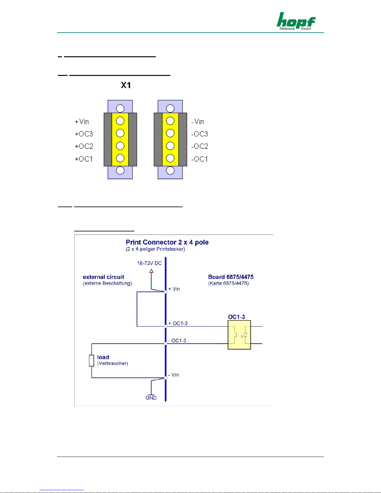
6 Examples of connections
6.1 Assignment of the screw clips
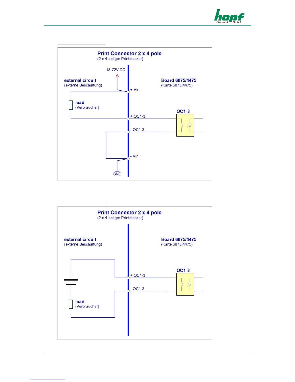
6.1.1 Examples of connections for OC1-3
Active, positive pulse
Page 51
EXAMPLES OF CONNECTIONS
GPS Satellite Controlled Clock 6875 - Ver. 04.00 Page 51
Active, negative pulse
Passive, positive pulse
Page 52
DIMENSIONS OF SNAP-IN MODULE HOUSING
Page 52 GPS Satellite Controlled Clock 6875 - Ver. 04.00
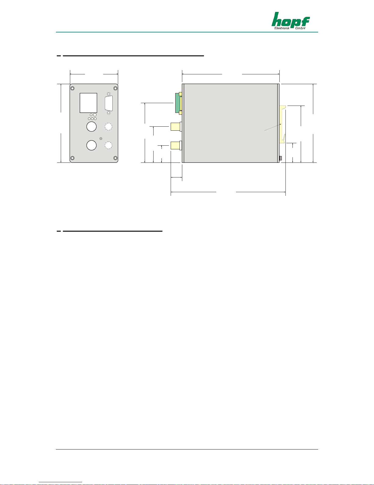
7 Dimensions of Snap-in Module Housing
Clip fastening for
mounting rail DIN EN 50 022
Klammerbefestigun g für
Tragschiene DIN EN 50022
7,5mm x 35mm oder 15mm x 35mm
7,5mm x 35mm oder 15mm x 35mm
Earth Screw
Erdungsschraube
64,5 (2.54”)
153,5 (6.04”)
105,0 (4.13”)
26,0
(1.02”)
76,0 (2.99”)
15,0
(0.59”)
130,0 (5.12”)
23,0
(0.91”)
48,0 (1.89”)
79,5 (3.13”)
105,0 (4.13”)
8 Glossary und Abbreviations
UTC Universal time coordinated
GPS Global positioning system
DCF77 (D) Deutsches (C) Langwellensignal (F) Frankfurt a.M. (77) Fre-
quenz in kHz German longwave signal Frankfurt a.M. Frequency
in kHz
PPS Pulse Per Second
Standard time Standard time – wintertime
DST Daylight Saving Time - summertime
IRIG-B Inter-Range Instrumentation Group B
AFNOR L’Association Française de Normalisation - Französische Gesell-
schaft für Normung (French Standards Association)
IEEE Institute of Electrical and Electronics Engineers
FL Fiber Optic Link
 Loading...