

Page 1
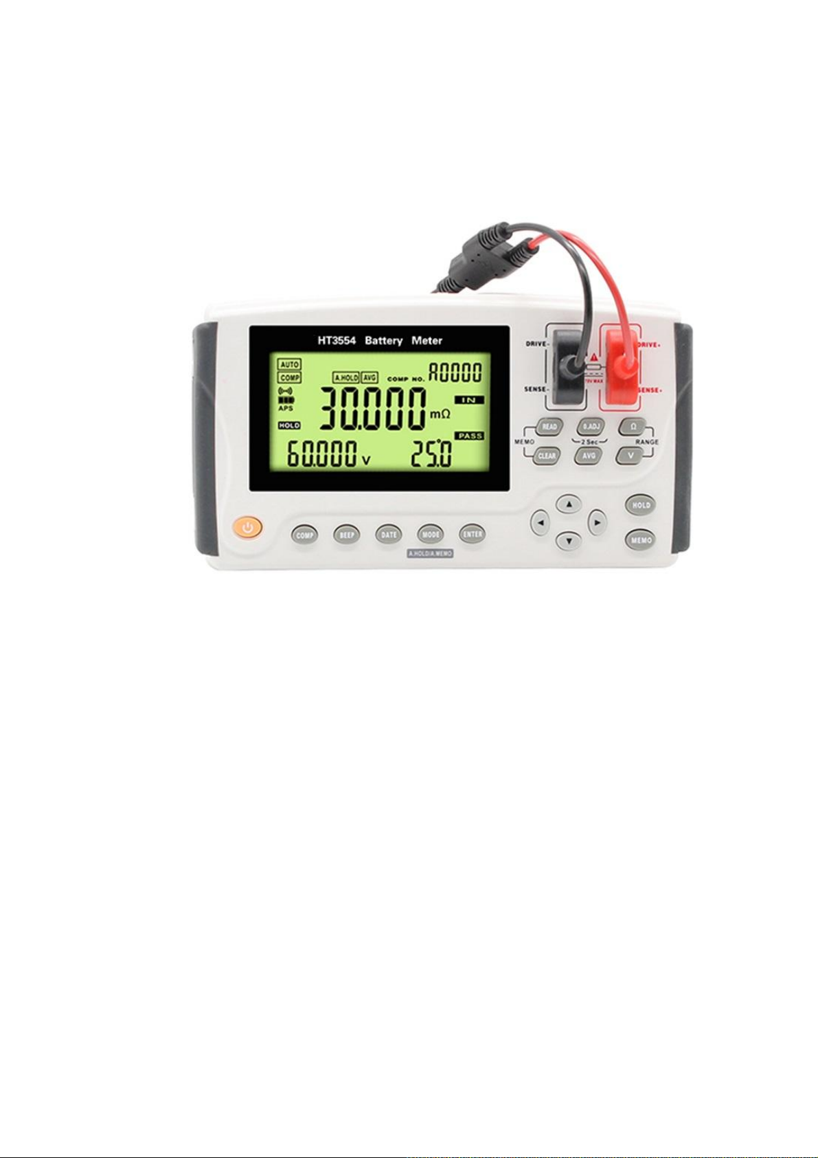
PORTABLE BATTERY TESTER
HT3554 HT3554A HT3554B HT3554D
Page 2

Contents
Introduction .............................................................................. 4
Checking Package Contents ......................................................... 4
Safety Notes .............................................................................. 6
Usage Notes .............................................................................. 8
Chapter 1 Overview ................................................................. 10
1.1 Overview .................................................................................................................... 10
1.2 Features ..................................................................................................................... 10
1.3 Names and Functions of Parts ................................................................................... 11
1.4 Measurement steps ................................................................................................... 13
1.5 Dimensions ................................................................................................................ 14
Chapter 2 Preparing for Measurement ....................................... 15
2.1 Attaching the Strap .................................................................................................... 15
2.2 Installing/Replacing Alkaline Batteries ...................................................................... 16
2.3 Connecting the Test Leads ......................................................................................... 18
2.4 Turning the Power On/Off ......................................................................................... 18
2.5 Clock Function ........................................................................................................... 19
Chapter 3 Basic Measurement ................................................... 21
3.1 Pre-operation Inspection ........................................................................................... 22
3.2 Setting the Measurement Range ............................................................................... 22
3.3 Zero Adjustment ........................................................................................................ 23
3.4 Retaining the Displayed Values ................................................................................. 25
3.5 Determining Battery-wear Judgment Values ............................................................ 26
3.6 Measuring the Temperature ..................................................................................... 26
Chapter 4 Comparator Function ................................................ 28
4.1 Overview ................................................................................................................. 28
4.2 Turning On the Comparator Function ....................................................................... 28
4.3 Select comparison mode ........................................................................................... 28
4.4 Set the comparator group number ........................................................................... 29
4.5 Set comparator .......................................................................................................... 29
4.6 Setting the Comparator Buzzer ................................................................................. 33
Chapter 5 Storage function ....................................................... 36
5.1 Overview .................................................................................................................... 36
5.2 Storing Data in the Memory ...................................................................................... 36
2
Page 3

5.3 Canceling the Memory Function ............................................................................... 37
5.4 Reading Out Stored Data ........................................................................................... 37
5.5 Clearing Stored Data .................................................................................................. 38
5.6 Download stored data ............................................................................................... 41
Chapter 6 Other Function ......................................................... 43
6.1.Averaging Function .................................................................................................... 43
6.2 Auto-hold Function .................................................................................................... 44
6.3 Auto-memory Function ............................................................................................. 44
6.4 Auto Power Save Function ........................................................................................ 45
6.5 Battery Level Warning ............................................................................................... 46
Chapter 7 Specifications ........................................................... 47
7.1 General Specifications ............................................................................................... 47
Chapter 8 Maintenance and Service ........................................... 49
8.1 Repair, Inspection, Cleaning ...................................................................................... 49
Chapter 9 Appendix ................................................................. 50
9.1 Effect of extended test line and induced voltage ...................................................... 50
9.2 Influence of Eddy Current....................................................................................... 50
9.3 AC 4-terminal Measurement Method .................................................................... 51
3
Page 4
Introduction
Thank you for purchasing Hope Instrument HT3554 series Battery Tester. To obtain maximum
performance from the product, please read this manual first, and keep it handy for future
reference.
Registered trademarks
Windows and Excel are registered trademarks of Microsoft Corporation in the United States or
other countries.
Checking Package Contents
When you receive the instrument, inspect it carefully to ensure that no damage occurred during
shipping. In particular, check the accessories, panel switches, and connectors. If damage is evident,
or if it fails to operate according to the specifications, contact your authorized Hope Instrument
distributor or reseller.
When transporting the instrument, use the same packaging materials used for the delivery to you.
Check the package contents as follows
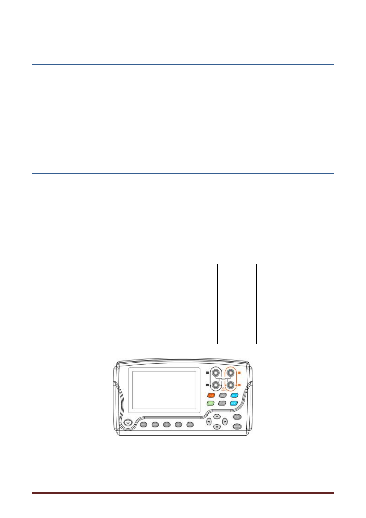
No. Item Quantity
1 Battery Tester 1
2 User s Manual 1
3 9803 USB Cable 1
4 Test lead 1
5 Strap 1
6 Lithium battery 1
7 Carrying Bag 1
HT3554 Battery Tester
4
Page 5
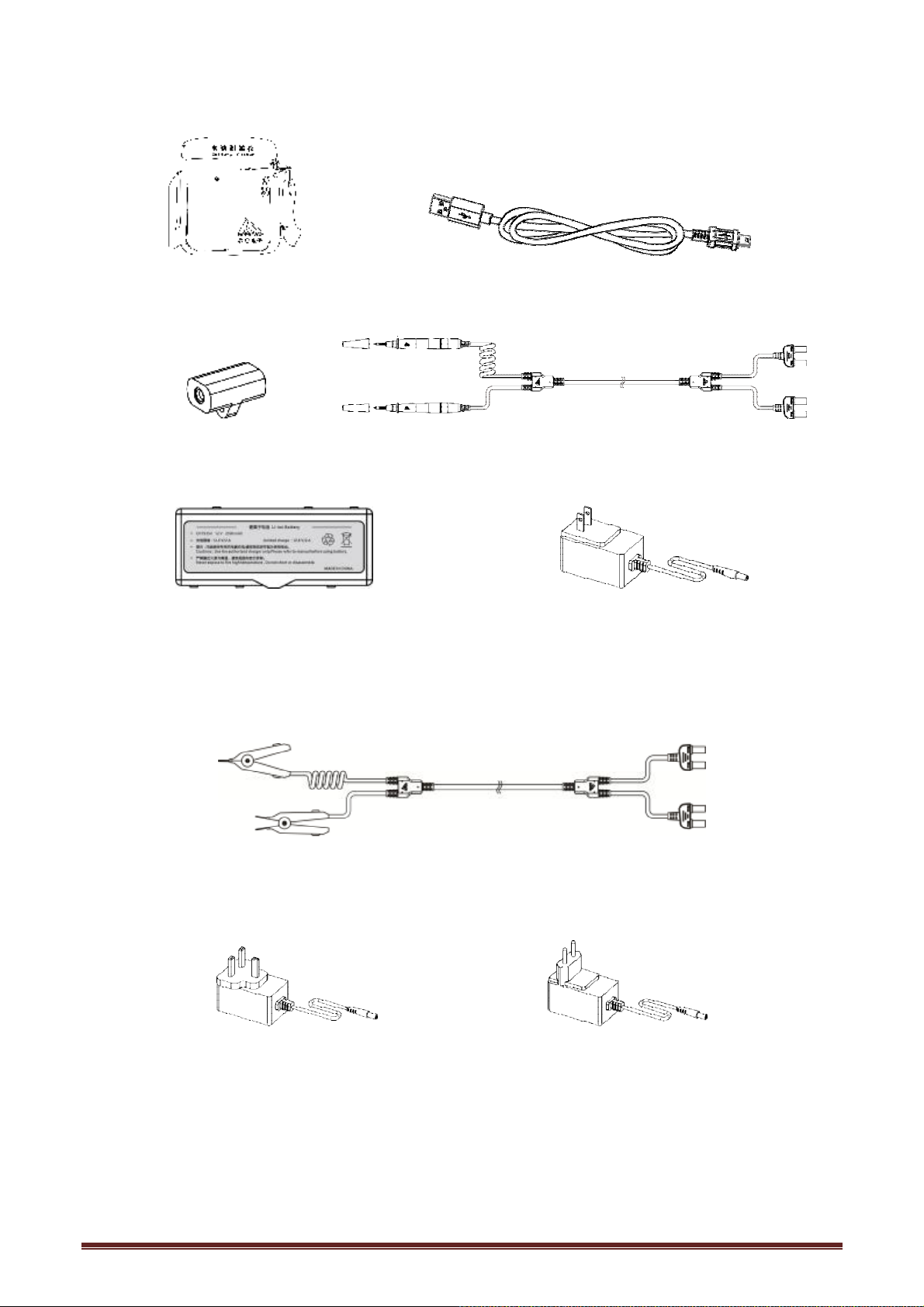
Carrying Bag 9803 USB Cable
zero adjustment block 9363-B Pin Type test lead(for HT3554)
Option
Lithium battery Battery Charger (Chinese standard)
9363-A Test Clip(for MP700500、MP700501、MP700502)
(British standard) (European standard)
Battery Charger
5
Page 6
Safety Notes
The instrument is designed to conform to IEC 61010 Safety Standards, and has been thoroughly
tested for safety prior to shipment. However, using the instrument in a way not described in this
manual may negate the provided safety features.
Before using the instrument, be certain to carefully read the following safety notes.
Note
Mishandling during use could result in injury or death, as well as damage to the instrument. Be
certain that you understand the instructions and precautions in the manual before use.
Notation
This manual contains information and warnings essential for safe operation of the instrument and
for maintaining it in safe operating condition. Before using the instrument, be certain to carefully
read the following safety notes.
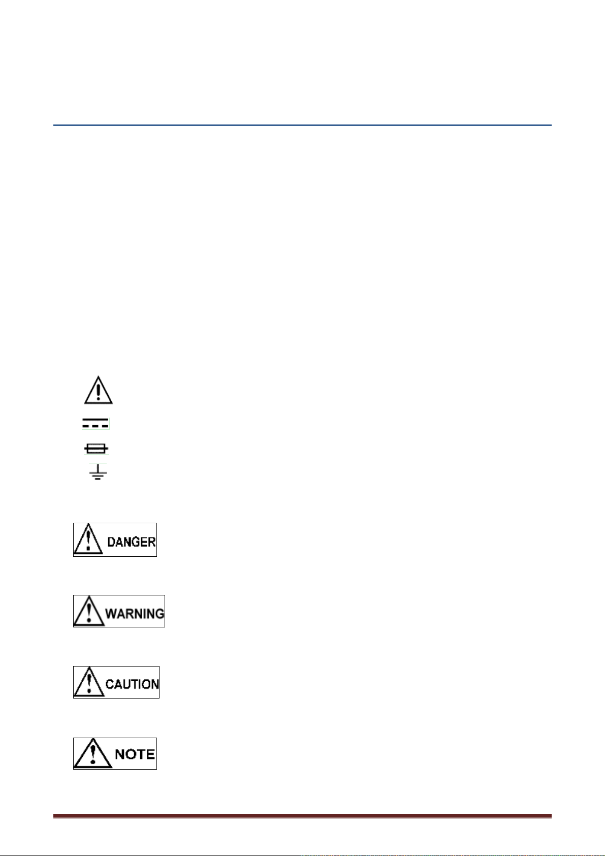
Indicates very important message in this manual. When the symbol is printed on the instrument,
refer to a corresponding topic in the Instruction Manual.
Indicates DC (direct current)
Indicates a fuse
Indicates earth terminal
In this manual, the risk seriousness and the hazard levels are classified as follows.
Indicates an imminently hazardous situation that will result in death or serious injury
to the operator.
Indicates a potentially hazardous situation that will result in death or serious injury
to the operator.
Indicates a potentially hazardous situation that may result in minor or moderate
injury to the operator or damage to the instrument or malfunction.
Indicates functions of the instrument or relative suggestion of a correct operation.
6
Page 7
Accuracy
We define measurement tolerances in terms of f.s. (full scale), rdg. (reading) and dgt. (digit) values,
with the following meanings:
f.s. (Maximum display value)
This is usually the maximum display value. In the instrument, this indicates
the currently used range.
rdg.
dgt.
(Reading or displayed value)
The value currently being measured and indicated on the measuring
instrument.
(Resolution)
The smallest displayable unit on a digital measuring instrument, i.e., the
input value that causes the digital display to show a !1".
7
Page 8
Usage Notes
Installation environment
² Operating temperature and humidity ranges
0#C to 40#C 80%RH or less (no condensation)
² Storage temperature and humidity ranges
23 $5#C 80%RH or less (no condensation)
Installing the instrument in inappropriate locations may cause a malfunction of instrument or may
give rise to an accident. Avoid the following locations.
² Exposed to direct sunlight or high temperature
² Exposed to corrosive or combustible gases
² Exposed to water, oil, chemicals, or solvents
² Exposed to high humidity or condensation
² Exposed to a strong electromagnetic field or electrostatic charge
² Exposed to high quantities of dust particles
² Near induction heating systems (such as high-frequency induction Heating systems)
² Susceptible to vibration
Checking before use
Before using the instrument, the first time, verify that it operates normally to ensure that no
damage occurred during storage or shipping. If you find any damage, contact your authorized Hope
Instrument distributor or reseller.
Before using the instrument, check that the coating of the test leads or cables are
neither ripped nor torn and that no metal parts are exposed. Using the instrument
under such conditions could result in electrocution. Contact your authorized Hope
Instrument distributor or reseller in this case
Handling Precautions
Do not modify, disassemble, or repair the instrument. This may result in fire, electric
shock accident, or injury.
Do not place the instrument on an unstable or slanted surface. It may drop or fall,
causing injury or instrument failure.
To avoid corrosion and/or damage to the instrument due to battery leakage, remove
the batteries from the instrument if it is to be kept in storage for an extended period.
Be sure to turn the power off after using it.
8
To avoid electric shock accident and short circuit, please operate the instrument as
following:
Page 9
VDC(HT3554B)/1000 VDC(HT3554D).
Do not test the terminal-to-ground voltage over 70 VDC(HT3554)/100
VDC(HT3554A)/300 VDC(HT3554B)/1000 VDC(HT3554D).
Do not test AC voltage.
Be sure to connect the test lead correctly.
Wear gloves of rubber or similar materials during measurement.
Ensure sufficient ventilation when testing batteries in the measurement room to
prevent explosions. Sparks may occur when the test leads are connected to batteries,
which can ignite any accumulated inflammable gases such as hydrogen.
Handling leads and cables
When using the instrument, use only the test line 9363-B or test leads specified by our
company.
To avoid damaging the cables, do not bend or pull the base of cables and the leads.
The ends of pin type leads are sharp. Be careful to avoid injury.
To avoid damage to the test leads, when plug/pull the test line, don’t hold the cable
but connector.
9
Page 10

Chapter 1 Overview
1.1 Overview
The HT3554 series Battery Tester measures internal resistance, voltage, and terminal
temperature of lead-acid, nickel-cadmium, nickel-hydrogen, and other types of batteries,
enabling you to determine if the battery is worn out.
The measurement data can be copied to a computer by connecting the instrument to a computer
after measurement with the USB cable provided.
1.2 Features
Enables measurement without shutting down UPS systems(only HT3554)
This instrument uses high-precision AC resistance measurement technology. Time required
for measurement is reduced since the instrument is capable of measuring live wires without
requiring the UPS system to be shut down.
Reliable measurement values
This instrument is capable of obtaining reliable measurement values without being affected by
lead or connector resistance because it uses the AC 4-terminal method to measure internal
resistance.
Simultaneous display of resistance, voltage, and temperature
Without changing functions, this instrument can display battery internal resistance, voltage, and
terminal temperature simultaneously.
Comparator function
The comparator function enables you to set threshold values for internal resistance and voltage.
This can determine battery wear more easily.
Large memory capacity
This instrument can store up to 2400 sets of data combining presently measured values
(resistance, voltage, temperature, and comparator measurement results). It can be used to
measure up to 12 units of 200-cell cubicles.
Auto-memory function
Turning this function on stores the measurement values in the instrument's internal memory
automatically, the instant when each set of data is held. This can lead to increased operational
efficiency.
PC interface
Measurement data can be loaded into a computer.
10
Page 11
Small size
Press the key to change the range by the
The instrument has a similar size with A5 paper,easy to carry.
Users will be not tired after long time operation since the instrument gross weight is only 800g.
Model 9363B Pin Type Lead
Using the model 9363B Pin Type Lead with a pin tip designed to fit in holes of %5 mm enables
measurement without removing terminal covers. Measurement is possible in virtually any
location because the pin can be inserted diagonally in hard-to-reach places.
Remote Control Switch (optional) for storing measurement values
The Remote Control Switch makes it possible to hold and store measurement values by
pressing a key. This is useful when both hands of the operator are busy.
1.3 Names and Functions of Parts
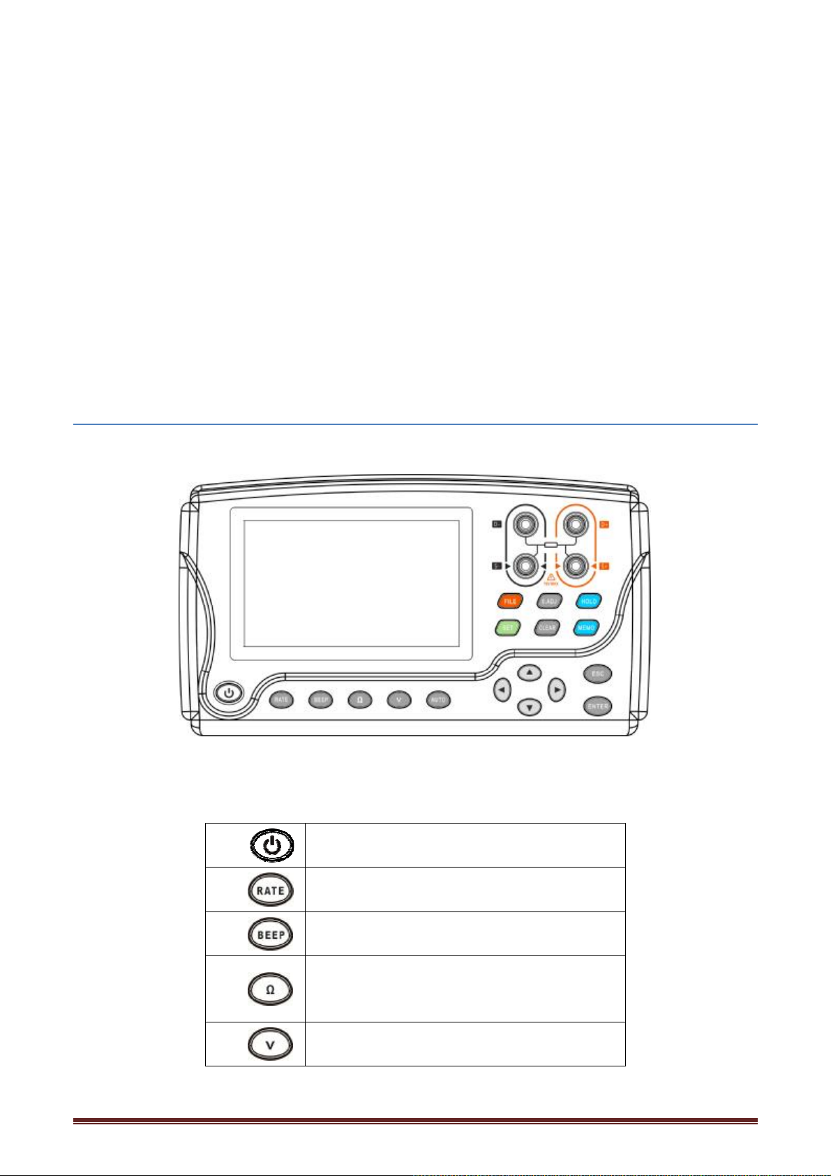
Front Panel
Turn the power ON/OFF.
Set test speed
Turn the comparator buzzer ON/OFF.
Changes the resistance range.
loop.
Changes the voltage range.
Press the key to change the range by the
11
Page 12
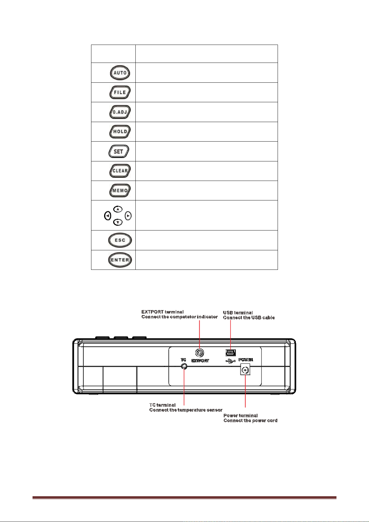
loop.
Set up automatic range test
Invokes the stored test value
Execute zero ajustment function
Holds or cancels the measurement values
Switch system setup interface
Deletes the settings
Stores display value to memory
Top view
Selects a configuration setting or changes
the value.
Exit the Settings
Confirms the settings.
12
Page 13
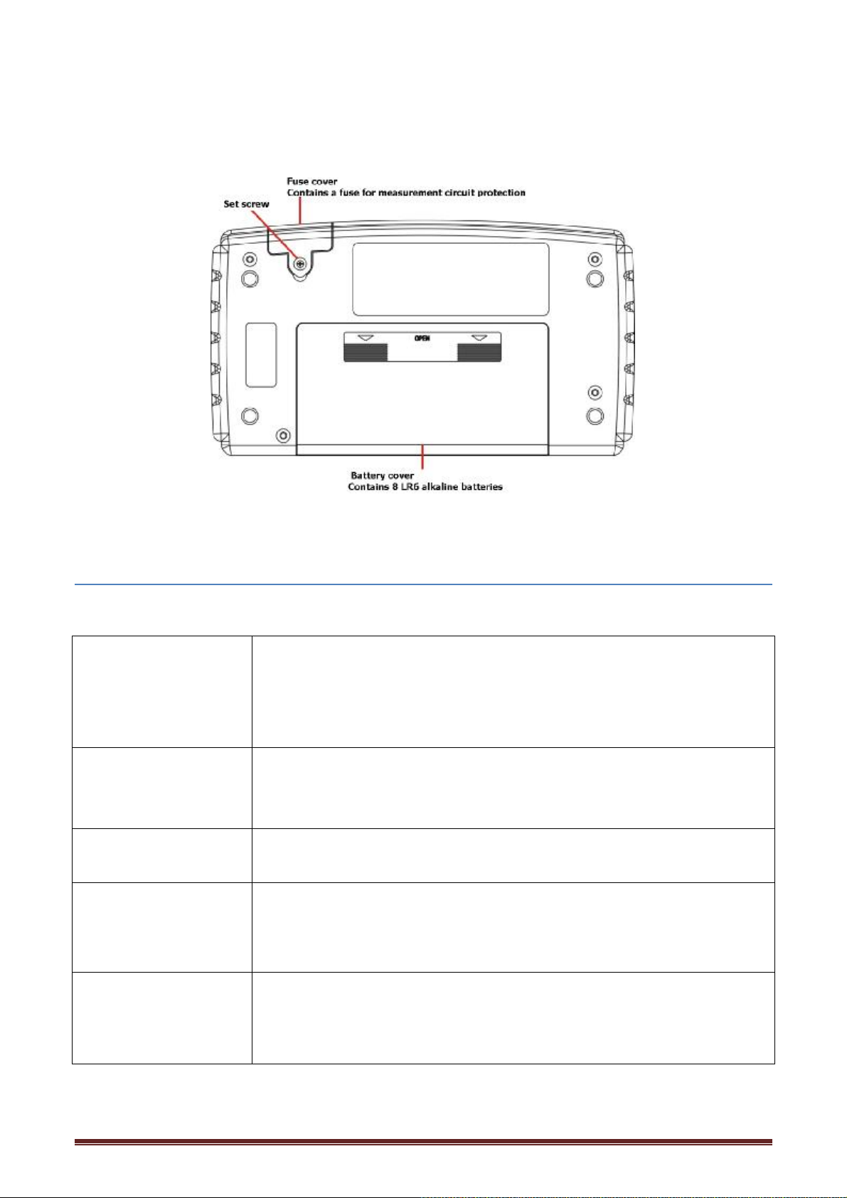
Rear view
1.4 Measurement steps
The measurement process is shown as below:
Measurement
preparation
Setting the
Measurement range
Zero Adjustment Performing zero adjustment is according to the zero ajusting method
Start of the test 1. Connect the test leads to the battery
End of the test 1.Disconnect the test lead and turn off the power
1. Install the neck strap
2.Check the remaining batteries of the instrument
3. Connect the test lead
4. Turning the Power ON/OFF
5. Set the clock
1. Set resistance range
2. Set voltage range
required by specified test leads
2. Read the measurement values
3. To retain measurement values
4. To store measurement values
2. By using the USB cable included with the instrument you can send the
stored data to a computer.(data transmission software needs to be
installed).
13
Page 14
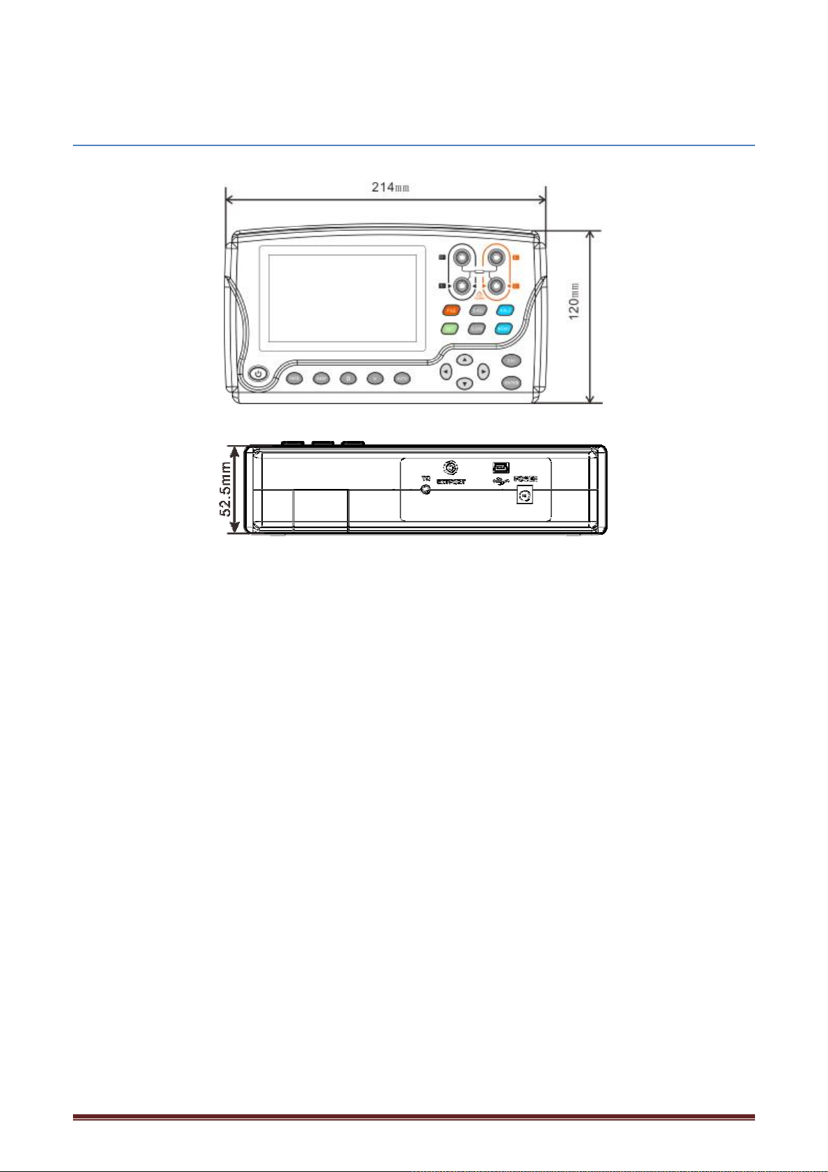
1.5 Dimensions
14
Page 15
Chapter 2 Preparing for Measurement
2.1 Attaching the Strap
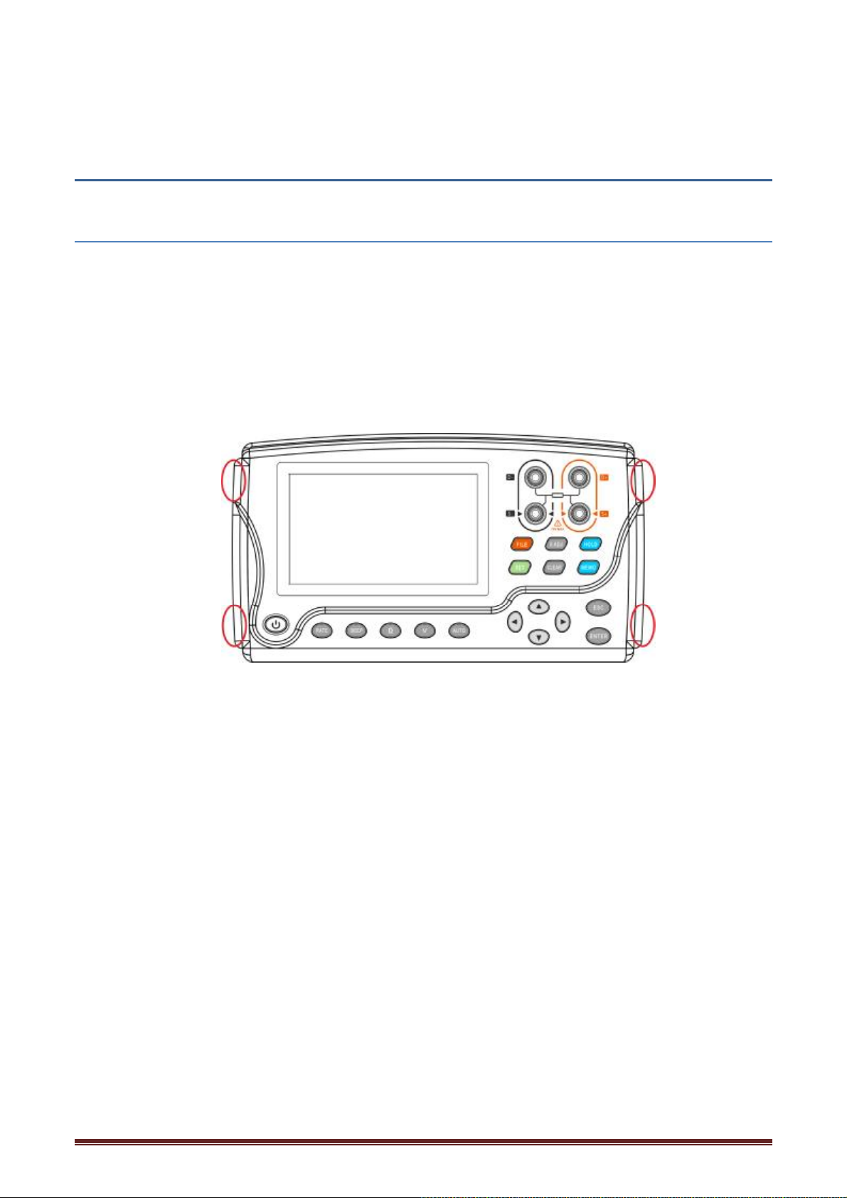
Attaching the strap to the instrument allows you to use it with the strap around your neck. Follow
the procedure below to attach the strap.
1. Switch off the instrument and remove the test leads.
2. Pass the neck strap through the attachments marked in red circle and fasten it in place with the
buckles.
3. Adjust the length of the neck strap.
Note:
Use the four attachment points on the instrument to attach the strap securely. Otherwise, the
instrument may drop during carrying, damaging the instrument and the operator may get hurt.
15
Page 16
2.2 Installing/Replacing Alkaline Batteries
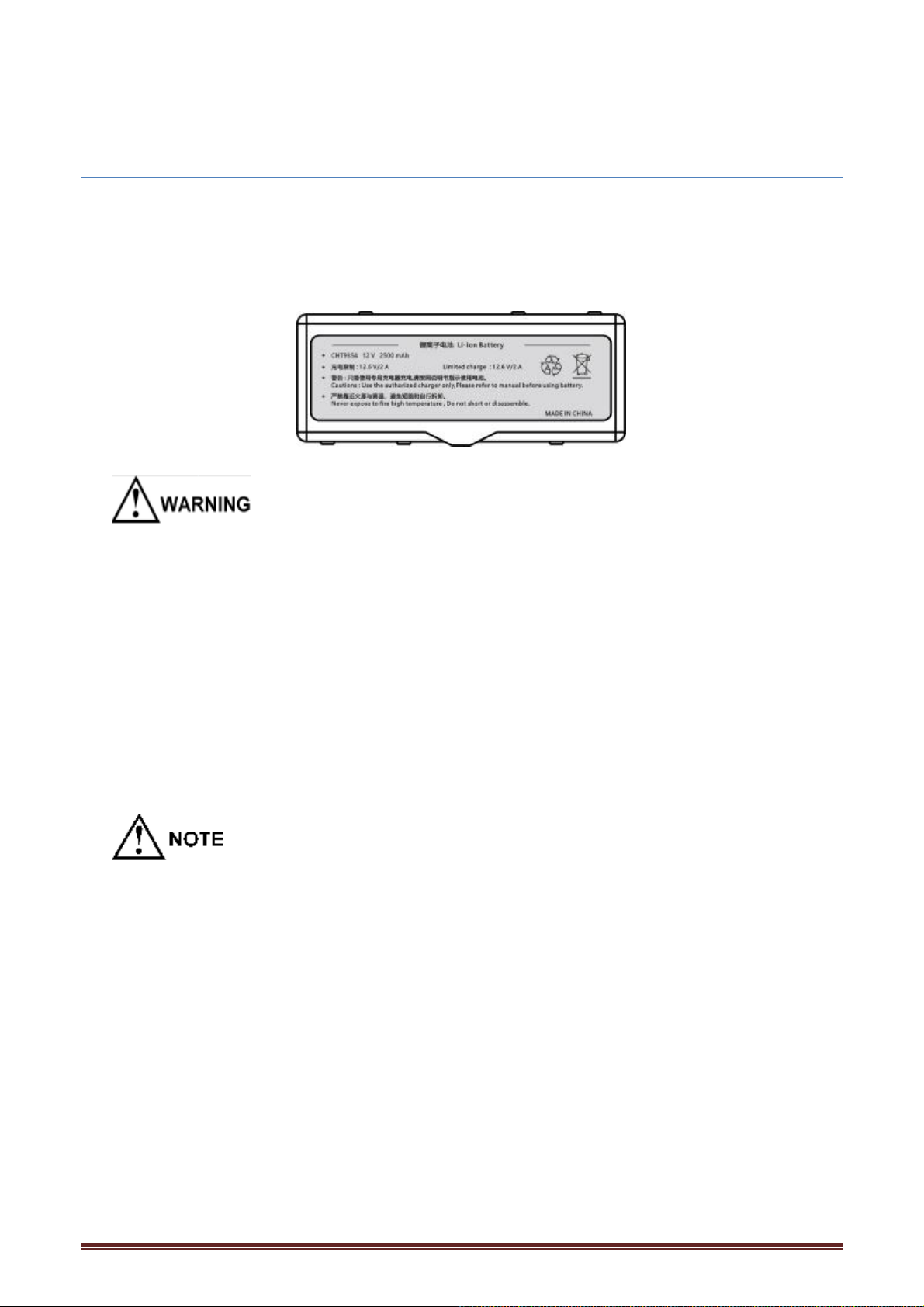
Before using the instrument for the first time, load the eight alkaline batteries (LR6) or the lithium
rechargeable battery. Before measurement, check that the instrument has sufficient remaining
battery power. If the remaining battery level is low, replace the batteries. See the battery indicator
to check the remaining battery level.
² Do not short circuit, charge, disassemble, or incinerate batteries. Doing so may cause an
explosion and is dangerous.
² To avoid electric shock accident, remove any test leads before replacing batteries.
² After the replacement, be sure to reattach the cover.
² Poor performance or damage from battery leakage could result. Observe the cautions listed
below.
² Do not use both old and new batteries or different types of batteries together.
² Be careful to observe battery polarity. Otherwise, poor performance or damage from battery
leakage could result.
² Do not use batteries after their recommended expiry date.
² Dispose of batteries in accordance with local regulations.
² When the remaining battery indicator is lit, the battery becomes low. Charge or replace the
batteries as soon as possible.
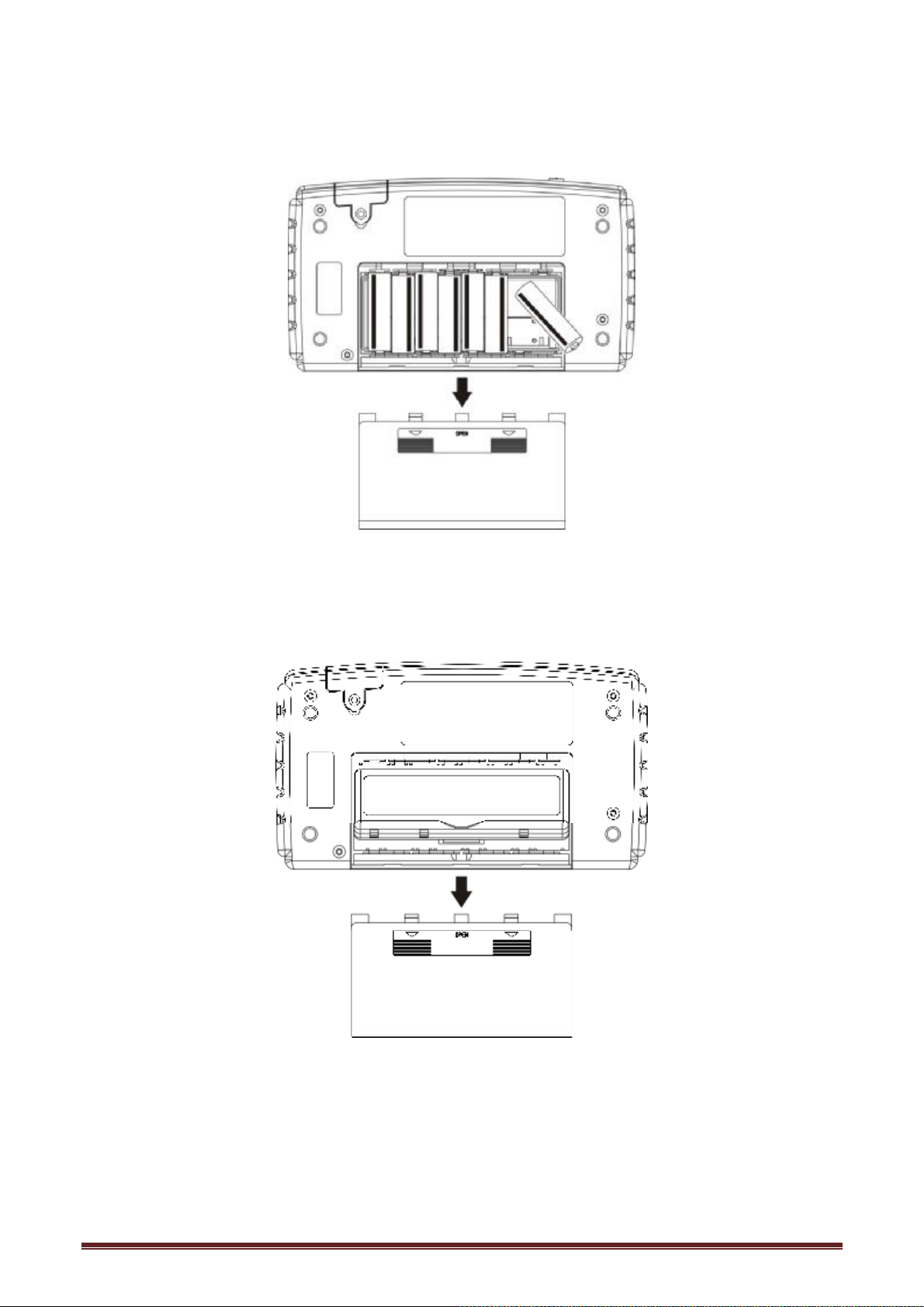
Replacing the battery steps:
1. Turn the power off. Remove any test leads.
2. Remove the battery cover on the back for the instrument.
3. Load the LR6*8 batteries or the lithium battery. Be careful of their polarity.
4. Reattached the battery cover on the back of the instrument.
16
Page 17
LR6 battery replacement
Lithium battery replacement
17
Page 18
2.3 Connecting the Test Leads
² To avoid electric shock accident, connect the test leads correctly.
² To be safe, do not use any test lead other than the ones specified by our company.
² The ends of leads are sharp. Be careful to avoid injury.
² Connect the test leads to the instrument. Connect the four terminals: DRIVE (+, -) and SENSE (+,
-).
2.4 Turning the Power On/Off
Press the [POWER] key to turn the power on or off. Check the clock settings when using
the instrument for the first time。
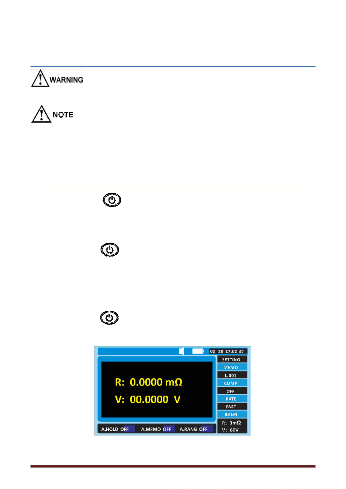
Turning the power on
Press the [POWER] key to turn the power on. Hold the key down until the entire display
turns on:
1. Display model and version number;
2. Entire display lit.
Turning the power off
Press the [POWER] key to turn the power off. Hold the key down until the entire display
turns off: Entire display off.
18
Page 19
2.5 Clock Function
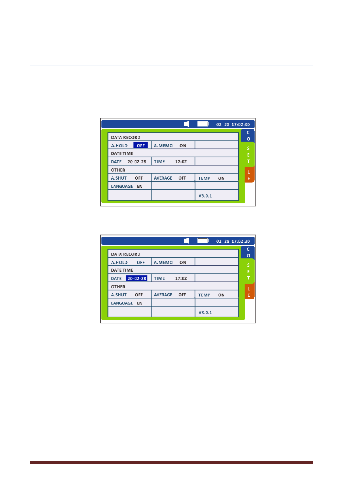
Date and time can be set in the system setup interface. Check the clock Settings the first time you
use this device.
2.5.1 Set the date
1. Press the [SET] key on the test page twice to switch to the system setting interface.
2. Select relevant options.
Press the direction key to move the cursor position, press the [ENTER] key to select the date, and
then press the direction key to adjust the value at the corresponding position.
3. Press the [ENTER] key to store the date and time Settings.
19
Page 20
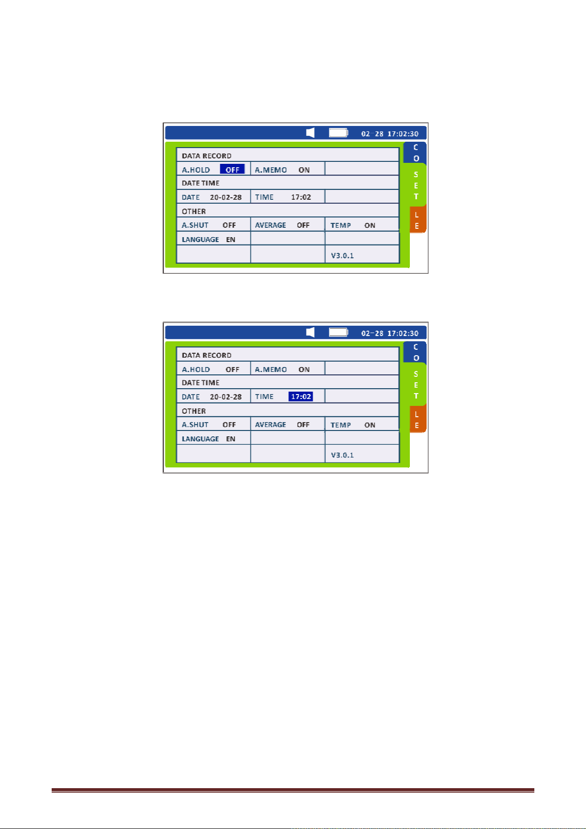
2.5.2 Set the clock
1. Press the [SET] key on the test page twice to switch to the system Settings interface.
2 Select the relevant options.
Press the direction key to move the cursor position, press the [ENTER] key to select the time,
and then press the direction key to adjust the value at the corresponding position.
3. Press the [ENTER] key to store the date and time Settings.
20
Page 21
Chapter 3 Basic Measurement
Before measurement, be sure to read this chapter.
To avoid electric shock accident and short circuit, please operate the instrument as following:
² Do not test the voltage over 70 VDC(HT3554)/100 VDC(HT3554A)/
300 VDC(HT3554B)/1000 VDC(HT3554D).
² Do not test the terminal-to-ground voltage over 70 VDC(HT3554)/
100 VDC(HT3554A)/300 VDC(HT3554B)/1000 VDC(HT3554D).
² Do not test AC voltage.
² If a voltage or current is applied beyond the rated range, the instrument will be damaged.
² After measuring the high voltage battery, you should put the test leads together and make
them shored first, and then test the low voltage batteries. In this way, the power of DC
cutoff capacitance can be removed, otherwise the overvoltage may damage the
low-voltage battery.
² Internal battery resistance varies considerably depending on charge or discharge status. To
increase measurement accuracy, make measurements under similar conditions (for
example, a fully charged battery).
² Lead-acid batteries (measuring objects) have high levels of terminal resistance. For this
reason, resistance values may differ between the case and the tip of the terminal. Be sure
to connect the test lead to the terminals at a fixed location.
² Use the optional Clip Type Lead with Temperature Sensor to measure the battery
temperature. Or, use a non- contact thermometer, such as a radiation thermometer, for
safety.
² Measurement may not be possible for insulated terminals, due to insufficient flow of
current for measurement. In such a case, clean the terminal (remove the insulation) before
measurement.
21
Page 22
3.1 Pre-operation Inspection
Inspection item Action
Is he fuse burned out?
Is the test lead
disconnected?
Is the battery level
sufficient?
Inspecting batteries
Touch the test lead to the zero adjustment board. If
the resistance display s&ll shows [''''], the fuse
might be burned out or the test lead may be
disconnected. If so, replace it with a new one.
At the upper left-hand area of the screen, indicates
the present alkaline battery status.
Measurement may not be possible for insulated
terminals, due to insufficient flow of current for
measurement. In such a case, clean the terminal
(remove the insulation) before measurement.
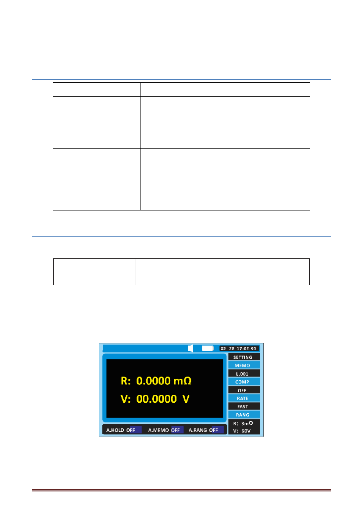
3.2 Setting the Measurement Range
Set resistance and voltage measurement ranges as described below.
Resistance range
Voltage range 6 V/ 60 V
3 m( / 30 m( / 300 m( / 3 (
Resistance range
Press the [Ω] key to set the current range. Press the key repeatedly to cycle through the ranges.
Voltage range
Press the [V] key to set the current range. Press the key repeatedly to cycle through the ranges.
22
Page 23
Manual range switching is effective even when the automatic range function is turned on (the
automatic range function is automatically turned off when the automatic range function is turned
on and the manual range function is turned off when the automatic range function is turned on)
At the measuring interface, press the [AUTO] key to switch the automatic range.
3.3 Zero Adjustment
The zero adjustment function displays subsequent measurement results using the measured value
(correction value) obtained when it was performed as zero.
The function is able to get a more reliable accurate measurement result. It is recommended to use
zero function before measurement.
² Performing zero adjustment adjusts the zero points of all ranges.
² It takes 5 seconds to perform the zero adjustment
² Even after the instrument is turned off, the correction values are retained and the zero
adjustment function is not canceled.
² After replacing the test lead, be sure to perform zero adjustment prior to measurement.
² Be sure to use the included zero adjustment block 9363-B when performing zero adjustment.
² Be sure to keep the test lead shorted during zero adjustment.
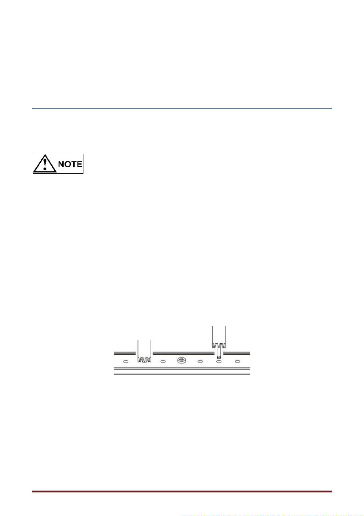
3.3.1 Shorting Methods for Various Test Leads
For Pin Type Leads 9363-B
Use the zero adjustment board included with the instrument. The zero adjustment can be achieved
using the AC 4-terminal method. Select the holes corresponding to the distance between the
battery ports, center on the center screw of the zero adjustment plate, and press down the test
probes symmetrically at both ends. The zeroing plate is at least 10 cm away from the instrument.
9365 zero adjustment plate
Or, using the zero adjustment block, insert the two ends of the probe into the middle hole of the
zero adjustment block and press down symmetrically.
23
Page 24
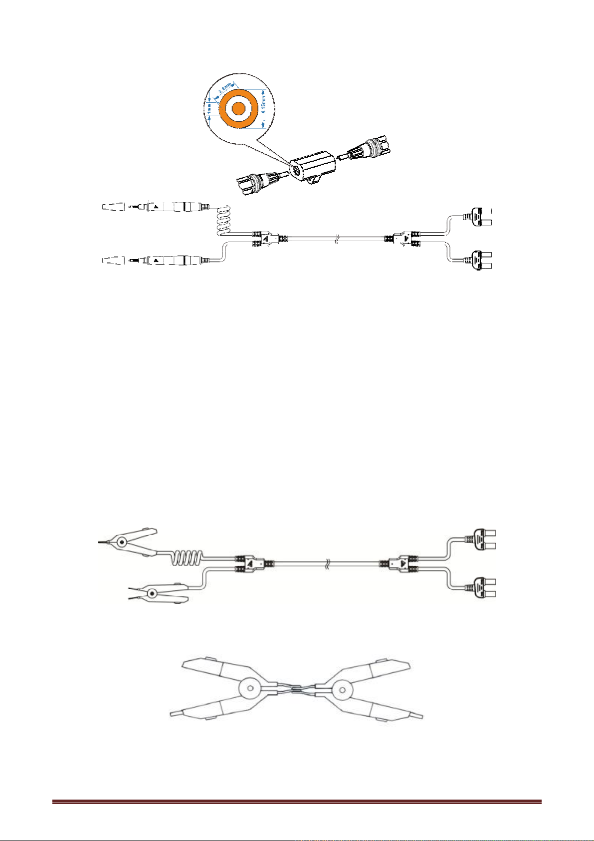
9363-B pin type test lead
Be sure to connect each of the DRIVE and SENSE terminals by inserting the tip of the pin into the
holes on the zero adjustment board. (See the figure above.)
Do not place the zero adjustment board on top of the battery or any metal. Electromagnetic
induction effect could result in unstable measurement values. In such a case, keep the zero
adjustment board away from any metal.
Be sure to use the included zero adjustment board when performing zero adjustment.
When the distance between the terminals on the battery (measurement target) is more than the
distance between the holes on the zero adjustment board, use the holes at both corners to perform
zero adjustment.
For Clip Type Leads
Perform zero adjustment by engaging red and black clips together.
9363-A test clip
3.3.2 Performing Zero Adjustment
24
Page 25
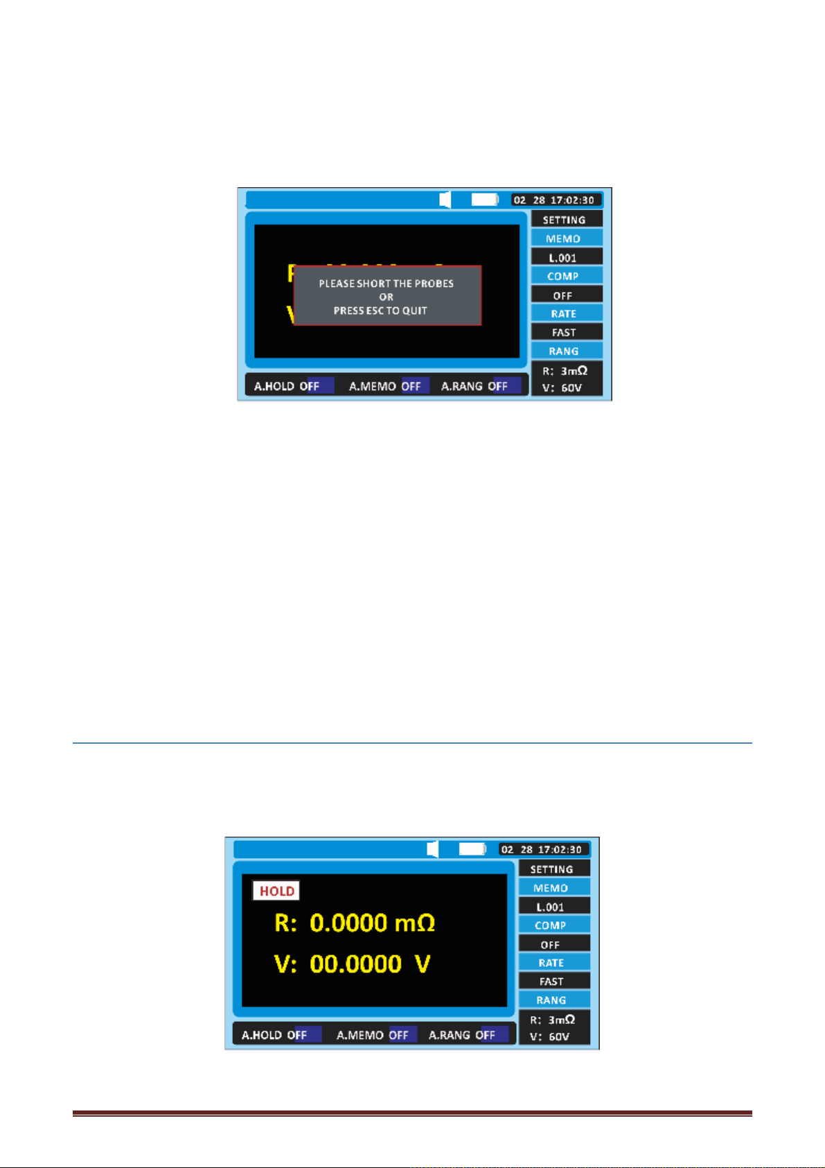
1. Check to ensure that the test leads are connected properly.
Disconnect any leads connected to the measurement target.
2. Press the [0.ADJ] key.
3. Press the key [ENTER] to perform zero adjustment.
If the test leads are not shorted while the display is blinking, it will result in an error.
When the screen shows error information: The error message is displayed without the correct
compensation value. The error may be caused by:
) for resistance or voltage values, the compensation value is over 300 units.
* Ensure that the test lead is properly connected to the instrument.
* The test lead is likely to be damaged. Try new test leads.
* Try to clean the zero adjustment board.
4. The instrument automatically begins obtaining correction values. When the zero adjustment
operation is complete, [0.ADJ] is lit up and the instrument returns to the measurement mode:
3.3.3 Canceling the Zeros Operation
When the zeroing function is performed, press [ESC] to cancel the zeroing adjustment operation.
3.4 Retaining the Displayed Values
3.4.1 Retaining the measurement values
Measurement values displayed on the screen can be retained. Pressing the [HOLD] key will light up
[HOLD], and retain the measurement values.
25
Page 26

3.4.2 Canceling the Retaining State
Pressing the [HOLD] key again cancels the retaining state.
When the warning display or voltage is displayed as [''''], the values cannot be retained.
² Changing any of the settings cancels retaining.
² Turning off the power cancels retaining.
3.5 Determining Battery-wear Judgment Values
1. Please refer to "pre-operation inspection of section 3.1" to set the range and zero operation.
2. The test lead is connected to a new or well-conditioned battery.
3. Read the measurement values.
4. Press the [HOLD] key to retain the measurement values.
) when the test value shows "OF", it indicates that the resistance or voltage value shown exceeds
the corresponding test range.
) when the resistance value is "--", it indicates that the test line is open or disconnected, or that the
current is unstable for other reasons and cannot be tested.
"--" will also be displayed when the test line is not properly connected to the measured object or
when the resistance of the measured object is far beyond the test range.
) when measuring the resistance of a relay or a connector, note the maximum open circuit voltage
(approx. 27 V) of the instrument. Measurements may damage the contact or oxide layer of the
object being measured, resulting in measurement errors.
End test
Press the [POWER] button to turn off the POWER of the instrument and remove the test line from
the instrument.
3.6 Measuring the Temperature
Press the [SET] key on the test page twice to switch to the system Settings interface.
26
Page 27
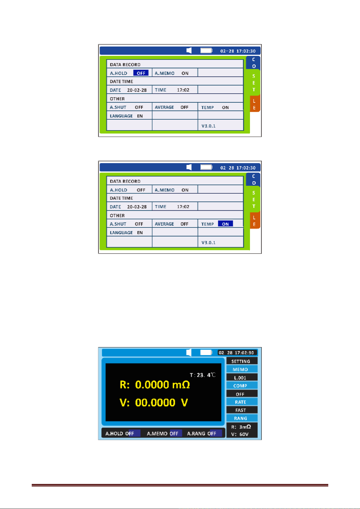
Select relevant options
Press the direction key to move the cursor position, press [ENTER] to select the temperature
measurement, and then press the left and right keys to turn on and off the temperature
measurement function.
3. Press [ENTER] to store the setting of temperature measurement function, and press [ESC] to
return to the measurement interface.
Use the optional model PT1000 Clip Type Lead with Temperature Sensor to measure the battery
temperature.
27
Page 28
Chapter 4 Comparator Function
4.1 Overview
The battery measurement values can be compared with the present threshold values using
the comparator function to determine the ranges in which the values fall within: PASS, or
FAIL. Up to 200 comparator conditions can be set.
A buzzer sounds when the test result is not qualified in the range.
4.2 Turning On the Comparator Function
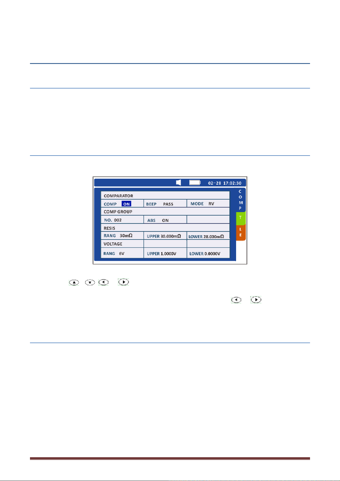
1.Press [SET] on the test page. Switch to the comparator interface.
2. Press the / / keys to move the cursor to the comparator switch position,
press [ENTER] to select the comparator switch, and then press the / keys to set the
comparator ON or OFF.
4.3 Select comparison mode
1. Press [SET] on the test page. Switch to the comparator interface.
28
Page 29
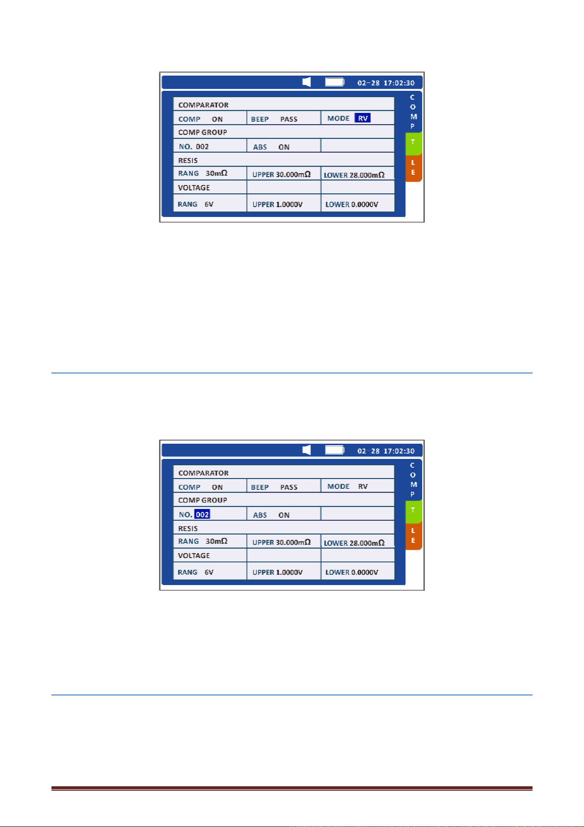
Press the direction key to move the cursor to the mode position, press the [ENTER] key to select
the comparison mode, and then press the left and right keys to set the comparison mode R, V or RV.
Press [ENTER] to store the comparison mode.
Mode R: compare resistance only, mode V: compare voltage only, mode RV: compare voltage
resistance.
4.4 Set the comparator group number
The instrument has the function of preserving 200 record groups.
1. Press [SET] on the test page. Switch to the comparator interface.
Press the direction key to move the cursor to the comparator group number, press the [ENTER] key
to set the group number, and then press the left and right keys to set the record group 1-200. Press
[ENTER] to store the comparator record group number.
4.5 Set comparator
Set the comparator threshold
1. Press [SET] on the test page. Switch to the comparator interface.
29
Page 30
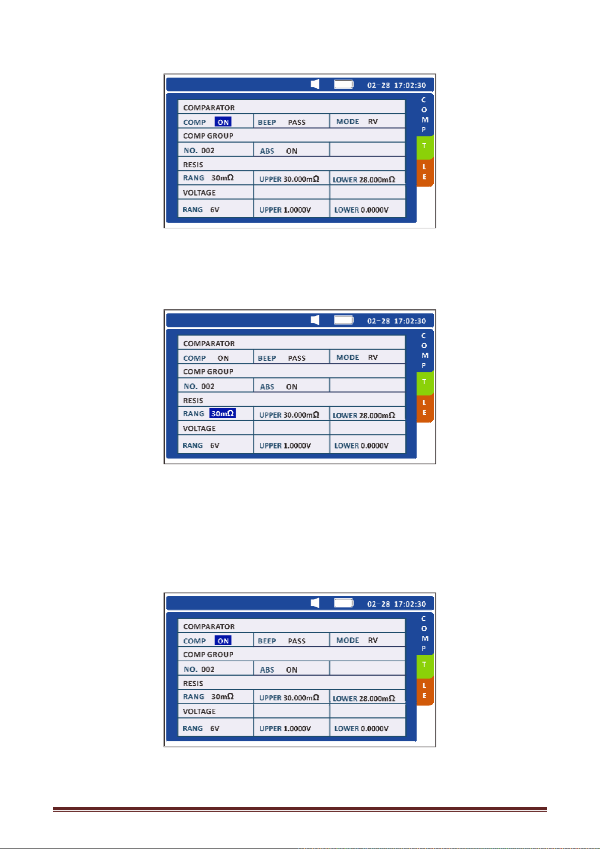
Press the direction key to move the cursor, press [ENTER] to select the comparator switch, and
then press the left and right keys to turn the comparator on or off.
2. Press the direction key to move the cursor to the resistance range position.
Press [ENTER] to select the resistance range to be set, and then press left and right to set the
resistance range. Press [ENTER] again to complete. Press [ESC] to return to the measurement
interface.
Set the comparator voltage threshold
1. Press [SET] on the test page. Switch to the comparator interface.
30
Page 31
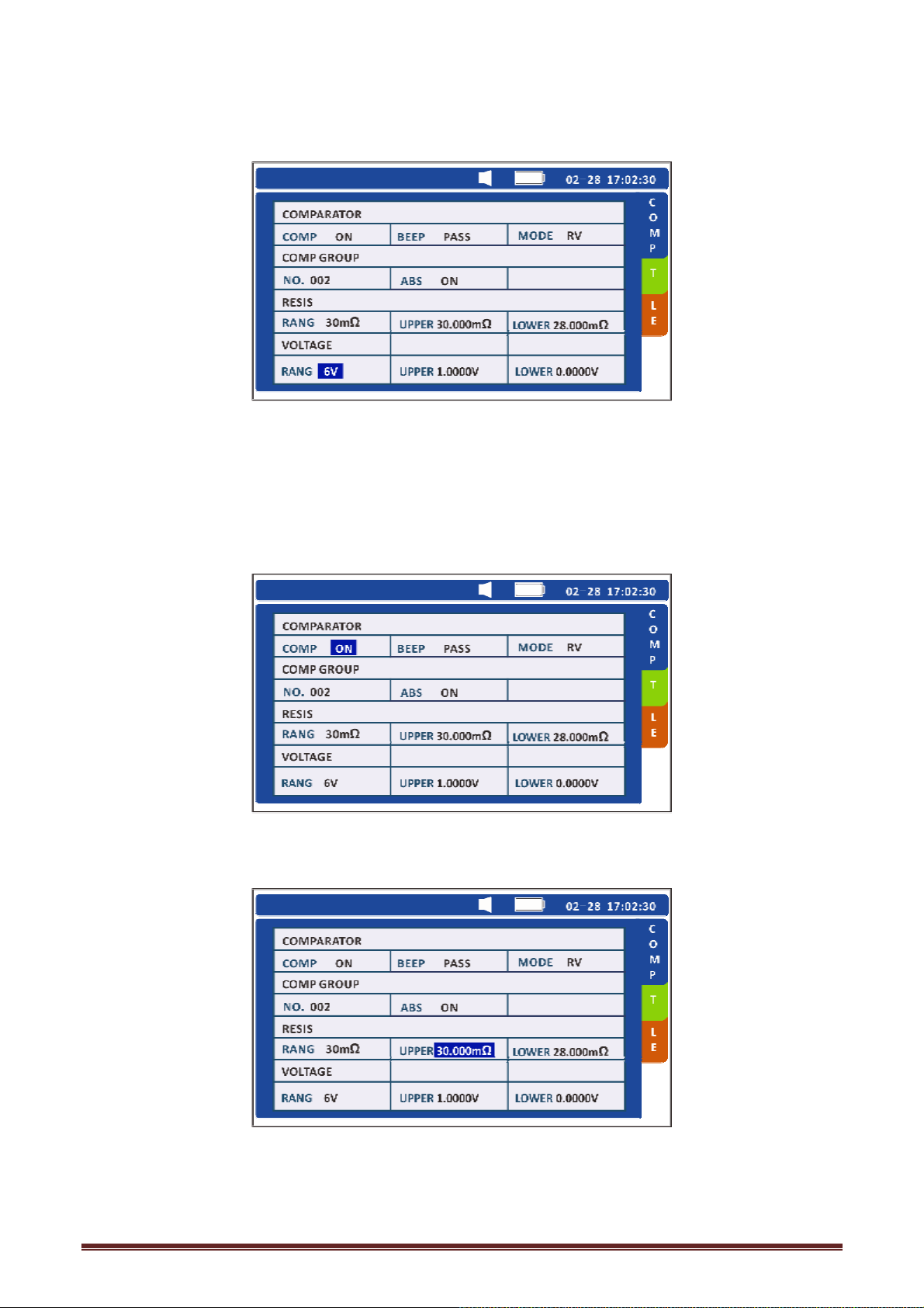
2. Press the direction key to move the cursor to the voltage range position.
Press [ENTER] to select the voltage range to be set, and then press the left and right keys to set the
voltage range. Press [ENTER] again to complete. Press [ESC] to return to the measurement
interface.
Set the comparator resistance threshold
1. Press [SET] on the test page. Switch to the comparator interface.
2. Press the direction key to move the cursor to the upper resistance position.
31
Page 32
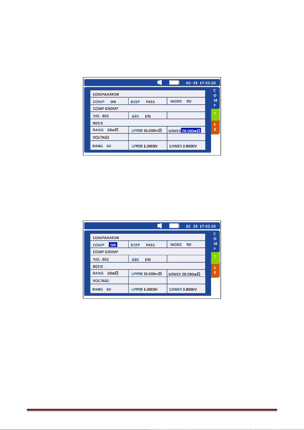
Press [ENTER] to select the upper limit of resistance to be set, press left and right keys to move the
cursor, and press up and down keys to set the upper limit of resistance. Press [ENTER] again to
complete.
3. Press the direction key to move the cursor to the lower resistance position.
Press [ENTER] to select the lower limit of resistance to be set, press left and right keys to move the
cursor, and press up and down keys to set the lower limit of resistance. Press [ENTER] again to
complete.
Set the comparator voltage threshold
1. Press [SET] on the test page. Switch to the comparator interface.
2. Press the direction key to move the cursor to the upper voltage position.
32
Page 33
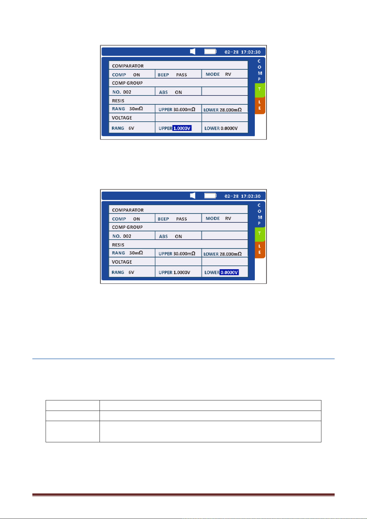
Press [ENTER] to select the voltage upper limit to be set, press left and right to move the cursor,
and press up and down to set the voltage upper limit. Press [ENTER] again to complete.
3. Press the direction key to move the cursor to the lower voltage position.
Press [ENTER] to select the voltage lower limit to be set, press left and right to move the cursor,
and press up and down to set the voltage lower limit. Press [ENTER] again to complete. Press [ESC]
to return to the measurement interface.
4.6 Setting the Comparator Buzzer
The buzzer can be enabled in accordance with comparison results when the comparator function is
used. The buzzer can be set to sound in the following states. By default, the buzzer is configured to
sound when the comparison result is WARNING or FAIL.
OFF The buzzer will not sound regardless of comparison results.
PASS(ON) The buzzer sounds when comparison results are PASS.
FAIL(ON)
When you press the [BEEP] key, the present comparator buzzer setting is displayed. Press the key
repeatedly to cycle through the settings.
33
The red backlight turns on, along with the buzzer sounds when
comparison results are WARNING or FAIL.
Page 34
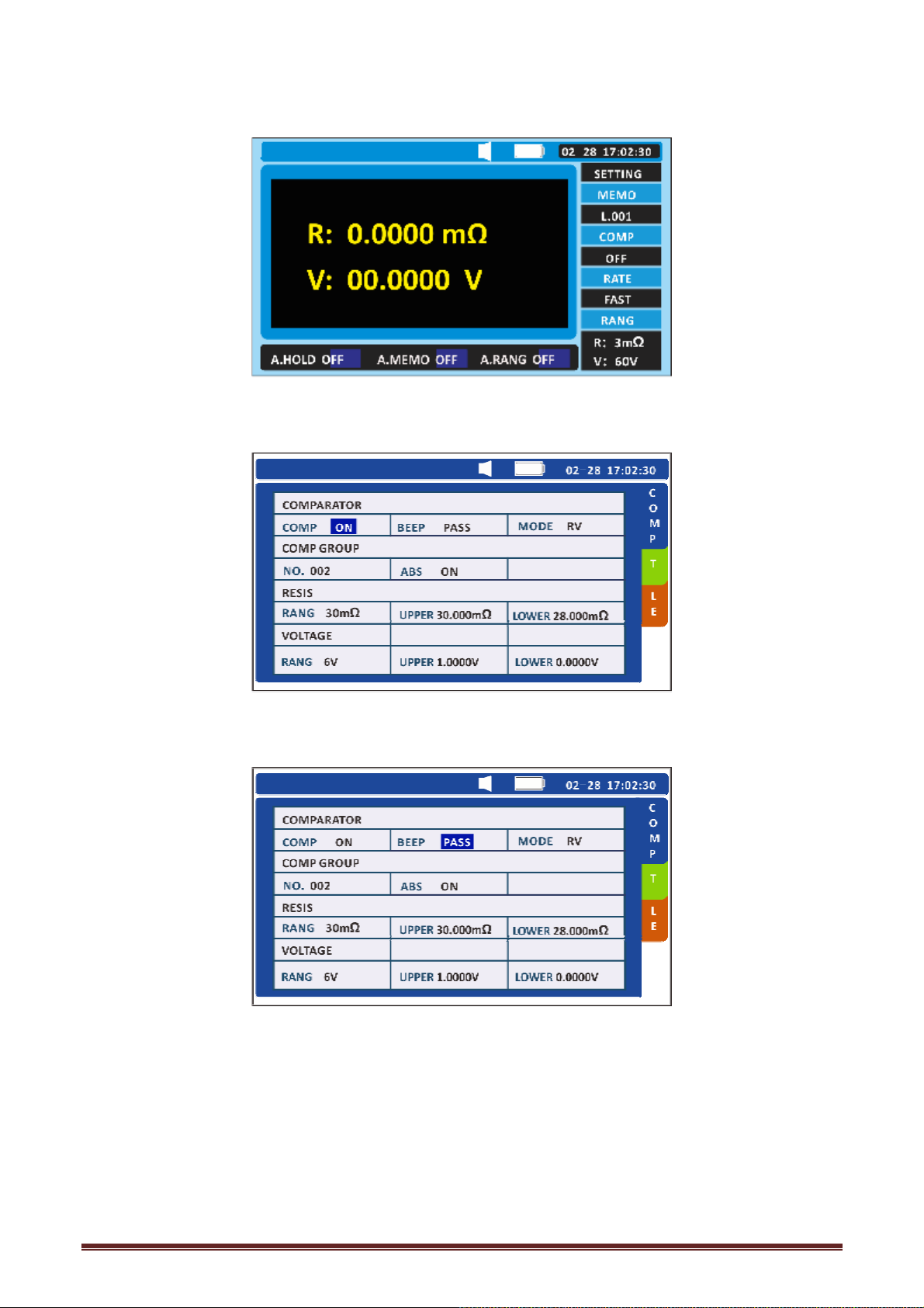
1. Press [SET] on the test page. Switch to the comparator interface.
2. Press the direction key to move the cursor to the signal.
Press [ENTER] to select the mode of message ringing that needs to be set, and press the left and
right keys to switch between qualified ringing and unqualified ringing. Press [ENTER] again to
complete.
34
Page 35

) The range keys cannot be used while the comparator function is turned on.
) If there are no measurement values, [''''] is displayed and a comparator judgment cannot be
performed.
) Even when the power is turned off, the comparator settings are saved and the comparator will
be restored to on when the power is again turned on.
35
Page 36

Chapter 5 Storage function
5.1 Overview
This instrument can store up to 2400 sets of data combining presently measured values*( Date and
time, resistance, voltage, temperature, comparator threshold values, and results of judgment).
After measurement, saved data can be displayed or transferred to a computer.
The structure of the internal memory is as follows:
Memory Structure
Unit name
(12 units)
A 1 2 3 ..... 198 199 200
b 1 2 3 ..... 198 199 200
C 1 2 3 ..... 198 199 200
d 1 2 3 ..... 198 199 200
E 1 2 3 ..... 198 199 200
F 1 2 3 ..... 198 199 200
G 1 2 3 ..... 198 199 200
H 1 2 3 ..... 198 199 200
J 1 2 3 ..... 198 199 200
Memory number (200 cells)
L 1 2 3 ..... 398 199 200
n 1 2 3 ..... 198 199 200
P 1 2 3 ..... 198 199 200
5.2 Storing Data in the Memory
Pressing the [HOLD] key and then press the [MEMO] key to save the current measurement values.
36
Page 37
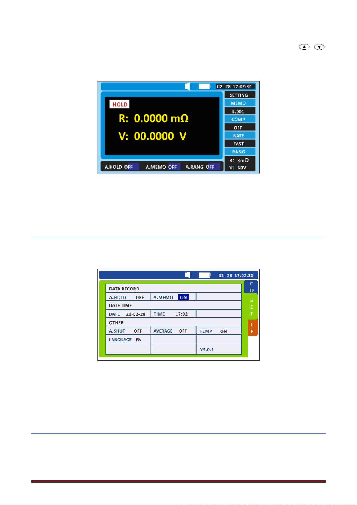
1. If the data is stored at a different address than the memory address shown, use the /
key to change the address cell number. This can be done at any time as long as storage is enabled.
2. Retain the measurement values by pressing the [HOLD] key.
3. Using the key [MEMO] to store the measurement values. The measurement values are stored in
the cell with the selected memory number.
4. After the data is stored, the next available memory number is displayed.
5.3 Canceling the Memory Function
1. Press the [SET] key on the test page. Switch to the system Settings interface.
2. Press the direction key to move the cursor to automatic storage.
3. Press the [ENTER] key to select ON or OFF to set the automatic storage function, and press the
left and right keys to switch OFF. Press [ENTER] again to turn off automatic storage. Press [ESC] to
return to the measurement interface.
5.4 Reading Out Stored Data
The stored measurement values are displayed after they are read out.
1. Press the [FILE] key on the test page. Switch to the file reading interface.
37
Page 38
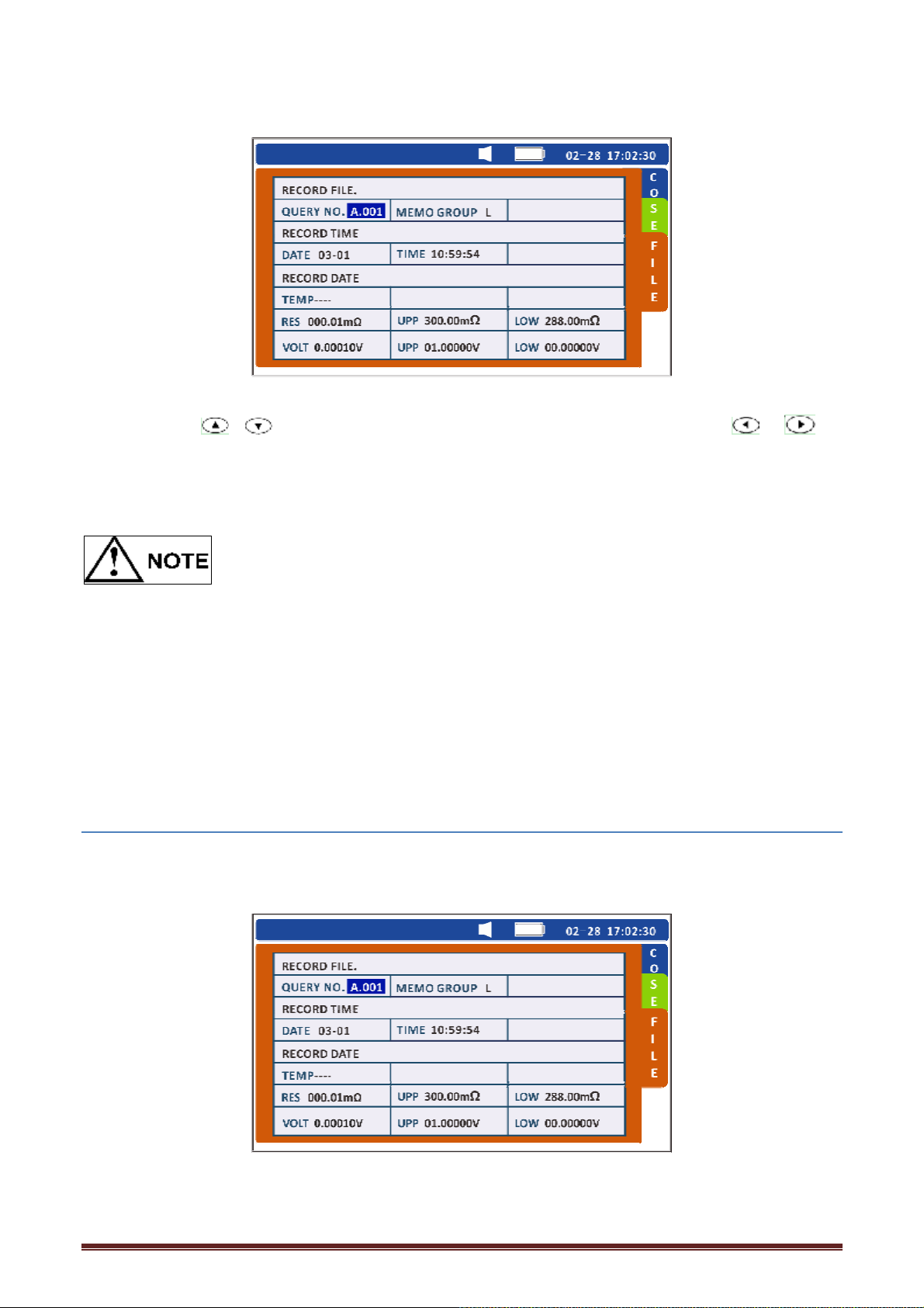
2. Use the key / to select the memory number to be read out. Use the key / to
locate the memory number The measurement values for the selected memory number are
displayed.
l Press the DATE key to check the date and time when the data was stored.
l The comparator result for the data being read out is also displayed.
l You cannot select the number of the memory location in which no data is stored.
l If no data has been stored, [''''] is displayed in the memory number display
l area and the instrument returns to the measurement screen.
l For data measured using the optional model PT1000 Clip Type Lead with Temperature Sensor,
the temperature is also displayed.
5.5 Clearing Stored Data
5.5.1 Clearing a group of data
1. Press [FILE] on the test page. Switch to the file reading interface.
38
Page 39
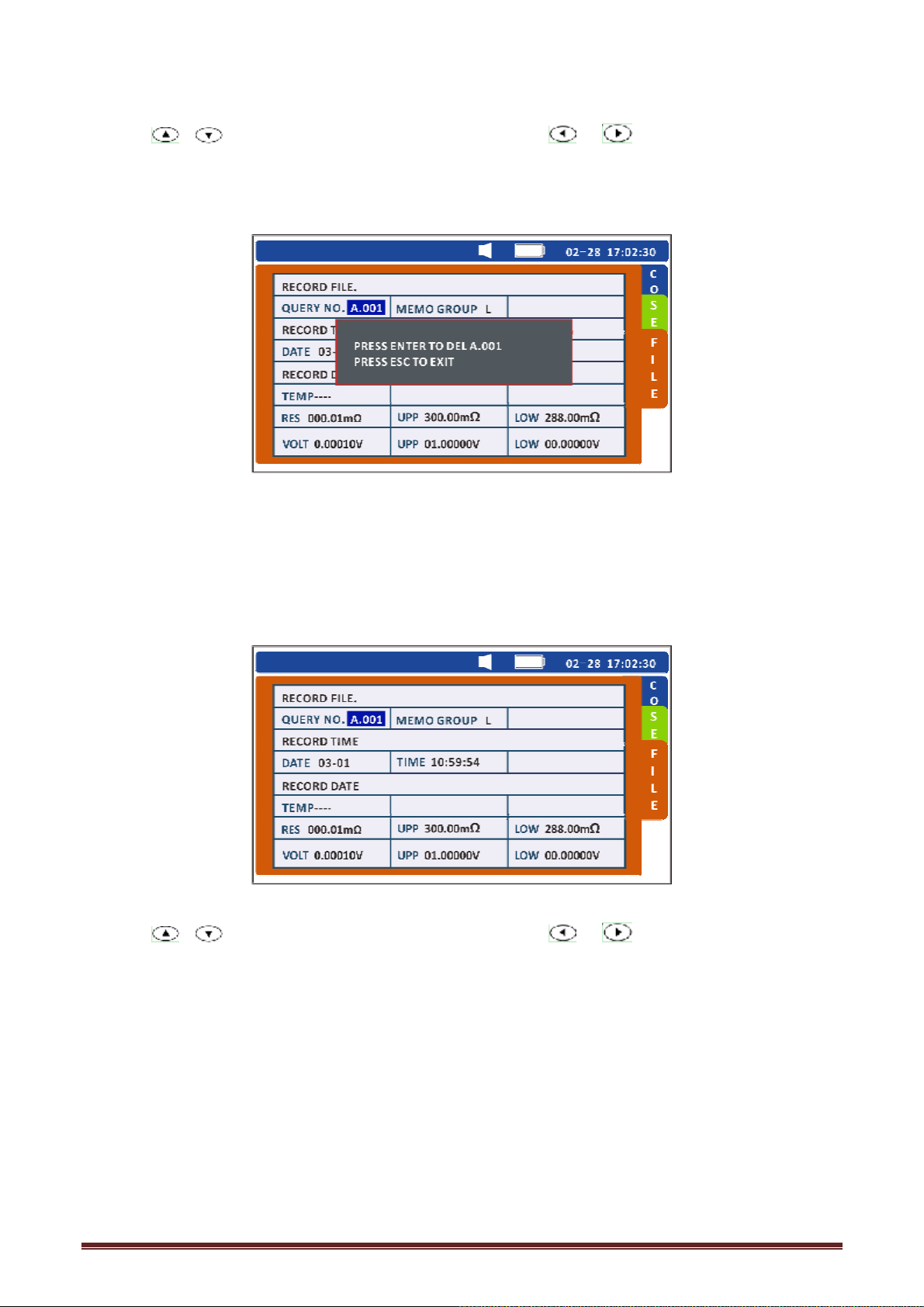
2. Press / to select the memory address unit. Press / to select a place.
3. Press [CLEAR] to delete the current group of data.
4. Press [ENTER] again to confirm that the data stored in the selected memory address is deleted.
5.5.2 Clearing a cell (200 groups) of data
1. Press [FILE] on the test page. Switch to the file reading interface.
2. Press / to select the memory address unit. Press / to select a place.
3. Press [CLEAR] twice to delete the cell data.
39
Page 40
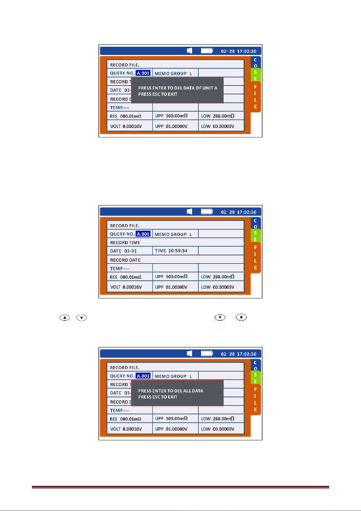
4. Press [ENTER] again to confirm that the data stored in the selected cell is deleted.
5.5.3 Clearing All Data
1. Press [FILE] on the test page. Switch to the file reading interface.
2. Press / to select the memory address unit. Press / to select a place.
3. Press [CLEAR] 3 times to delete all data.
4. Press [ENTER] again to delete all the stored data.
40
Page 41
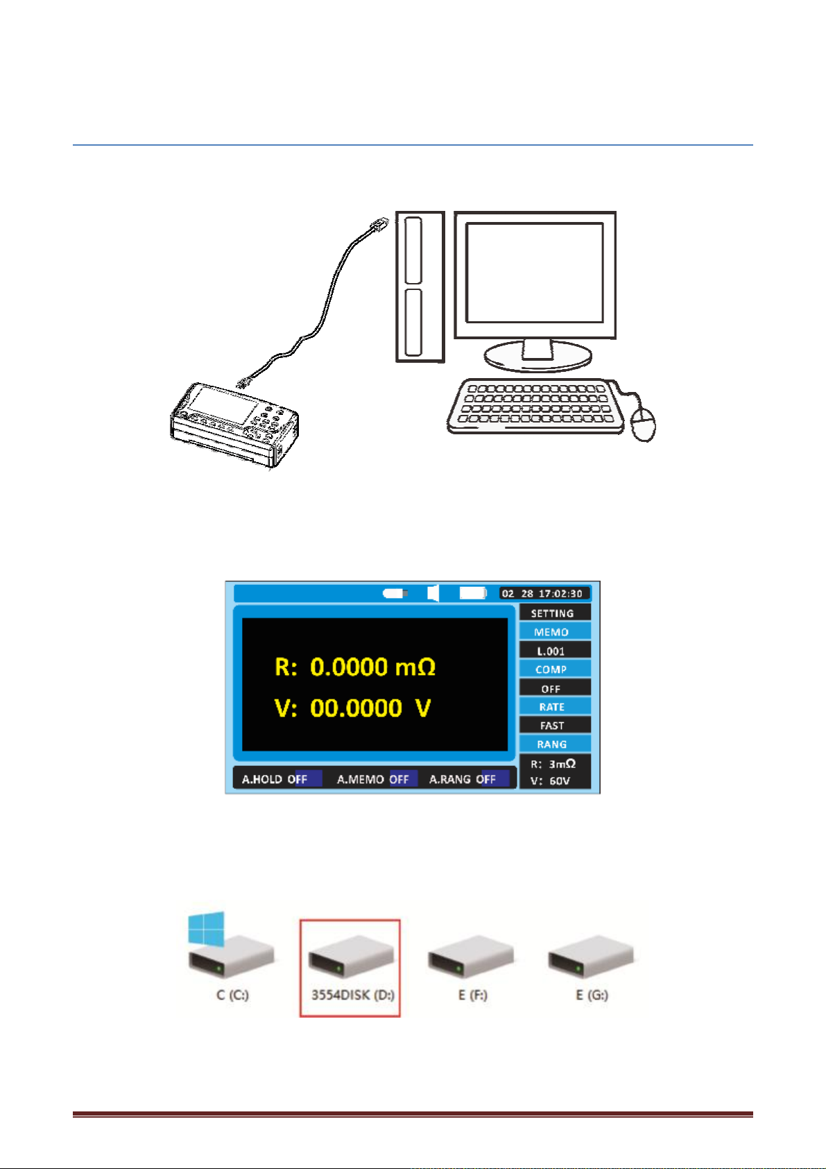
5.6 Download stored data
The test is complete and the stored test data can be downloaded to the computer.
1.Connect one end of the 9803 USB communication cable to the personal computer and the other
end to the PC interface above the HT3554.
2. When the cable is connected, USB small icon appears in the status bar above the tester, and the
3554 DISK is found on the computer.
41
Page 42

3.Open the 3554DISK, the data is stored in the FILE_A、FILE_B and other files inside, which can be
Resistance(mΩ)
Low Setting(mΩ)
High Setting(mΩ)
Voltage(V)
Low Setting(V)
High Setting(V)
downloaded according to the need.
Open as follows:
Battery Test
Serial Number HP3554
Test Start Date&Time00-268470120 05:00:15469
Memory Location A
Battery Location
Battery Type
Battery No.
1 1.5192 1.0000 2.0000 4.05856 3.60000 4.30000PASS 21.02020/4/30 10:59
2 1.5170 1.0000 2.0000 4.05850 3.60000 4.30000PASS 21.12020/4/30 10:59
3 1.5167 1.0000 2.0000 4.05860 3.60000 4.30000PASS 21.22020/4/30 10:59
4 1.5130 1.0000 2.0000 4.05959 3.60000 4.30000PASS 21.02020/4/30 11:00
5 1.4950 1.0000 2.0000 4.05753 3.60000 4.30000PASS 20.92020/4/30 11:00
6 1.5000 1.0000 2.0000 4.05844 3.60000 4.30000PASS 21.02020/4/30 11:02
7 2.1078 1.0000 2.0000 4.05851 3.60000 4.30000FAIL 21.32020/4/30 11:03
Pass/FailTemp(℃)Test Date&Time
42
Page 43
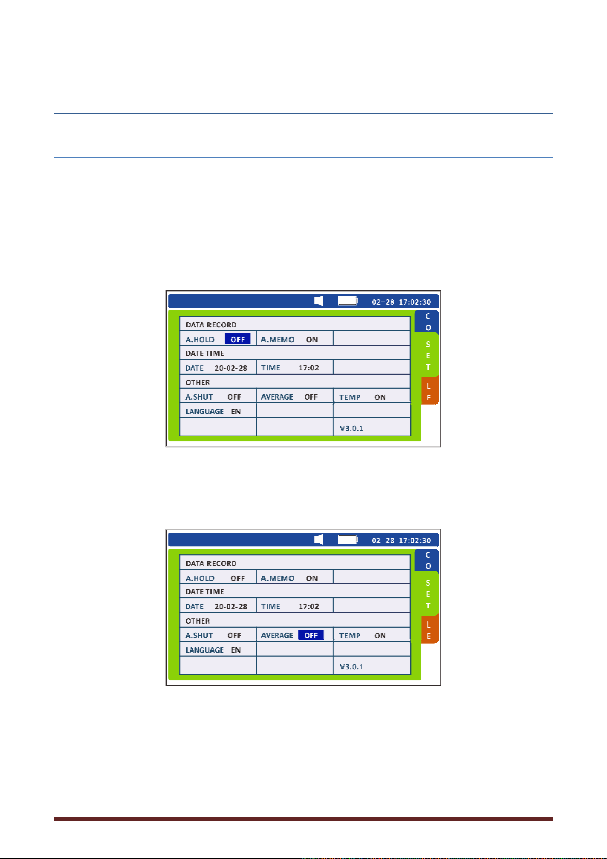
Chapter 6 Other Function
6.1.Averaging Function
This function averages the measurement values in order to display a single value. It helps to
stabilize fluctuations in the measured values.
When the test value is not stable, the average function can be used. The average number can be
selected as 2, 3, or 4.
1. Press [SET] on the test page. Switch to the system Settings interface.
2. Press the direction key to move the cursor to the average number of times.
Press [ENTER] to select the average number of times you want to set, and press left and right to
switch OFF, 2,3,4. Press [ENTER] again to complete. Press [ESC] to return to the measurement
interface.
43
Page 44
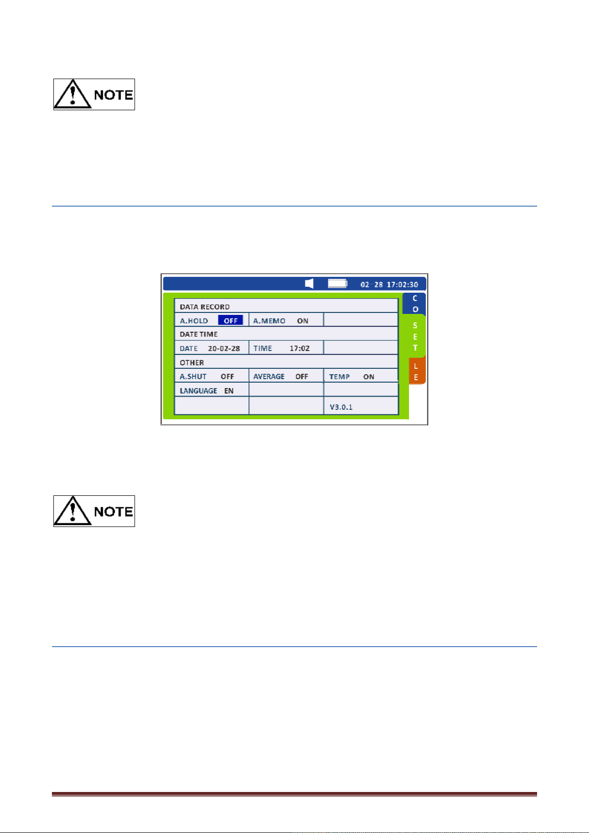
l The average function can be used when measure resistance values.
l The average function is used to change the display update rate of the test value.
l When the average function is not used, select "OFF".
6.2 Auto-hold Function
This function automatically recognizes the stability of measurement values and retains them.
Set auto hold function
1. Press [SET] on the test page. Switch to the system Settings interface.
Press the [ENTER] key to select whether to turn ON the auto save function, and press the left
and right keys to switch OFF, ON. Press [ENTER] again to complete. Press [ESC] to return to the
measurement interface.
•
When ['''']is displayed, data is not retained automa+cally.
•
The instrument retains and stores measurement values automatically when the auto-memory
function is used together with this function.
6.3 Auto-memory Function
This function automatically stores measurement values in memory immediately after they are
retained.
Set up automatic storage
1. Press [SET] on the test page. Switch to the system Settings interface.
44
Page 45
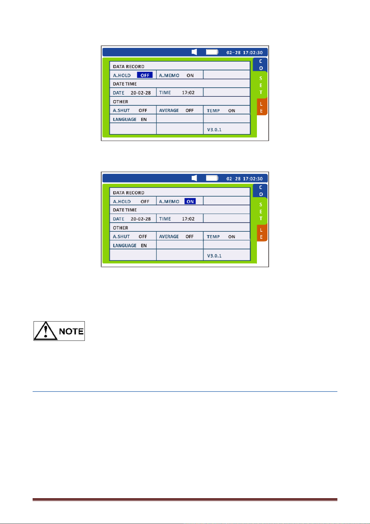
2. Press the direction key to move the cursor to the automatic storage function.
Press the [ENTER] key to turn ON or OFF the automatic storage function, and press the left and
right keys to switch OFF, ON. Press [ENTER] again to complete. Press [ESC] to return to the
measurement interface.
The instrument retains and stores measurement values automatically when the auto-memory
function is used together with auto-hold function.
6.4 Auto Power Save Function
The auto power save function can be used to reduce power consumption of the instrument. The
instrument is turned off automatically if any of the following conditions continues for
approximately 10 minutes with no key operation:
) [''''] is displayed as a resistance value.
) Data is being retained. (Measurement is suspended.)
) A state other than measurement state. (Any of the setup screens or the data readout screen is
displayed.)
) After completion of communication.
45
Page 46
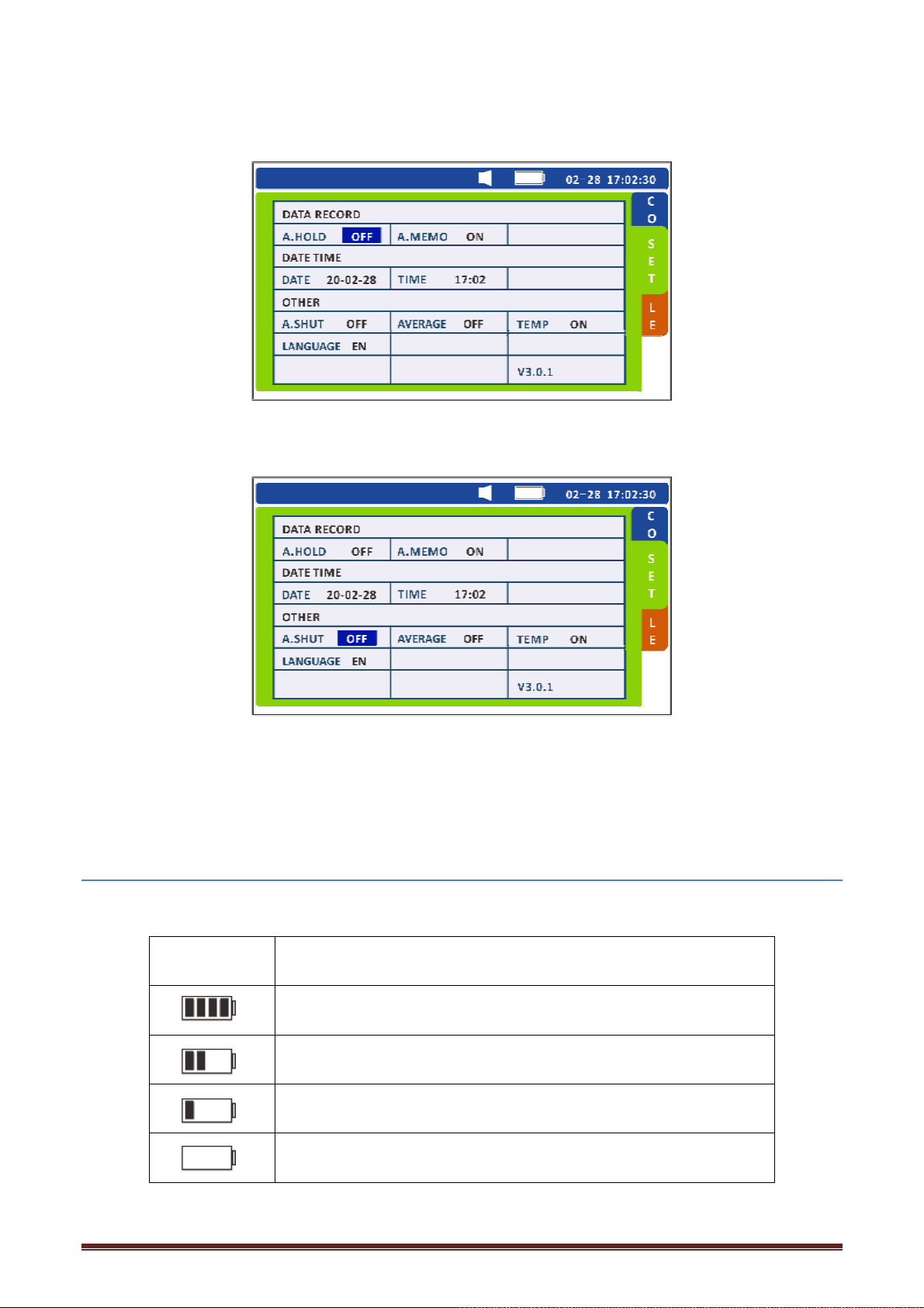
1. Press [SET] on the test page. Switch to the system Settings interface.
2. Press the direction key to move the cursor to automatic shutdown.
Press [ENTER] to select the automatic shutdown function, and press the left and right keys
to switch OFF, ON. Press [ENTER] again to complete. Press [ESC] to return to the measurement
interface.
6.5 Battery Level Warning
The battery level of the instrument is displayed at the upper-right corner of the screen.
Battery
level indicator
Battery status when it is used about 6 hours
Battery status
Battery fully charged.
Battery status when it is used about 4 hours
Battery level is low. Charge the battery timely
(Flashing) Battery status when it is used about 8 hours
Battery level is low. Charge the battery as soon as possible
46
Page 47
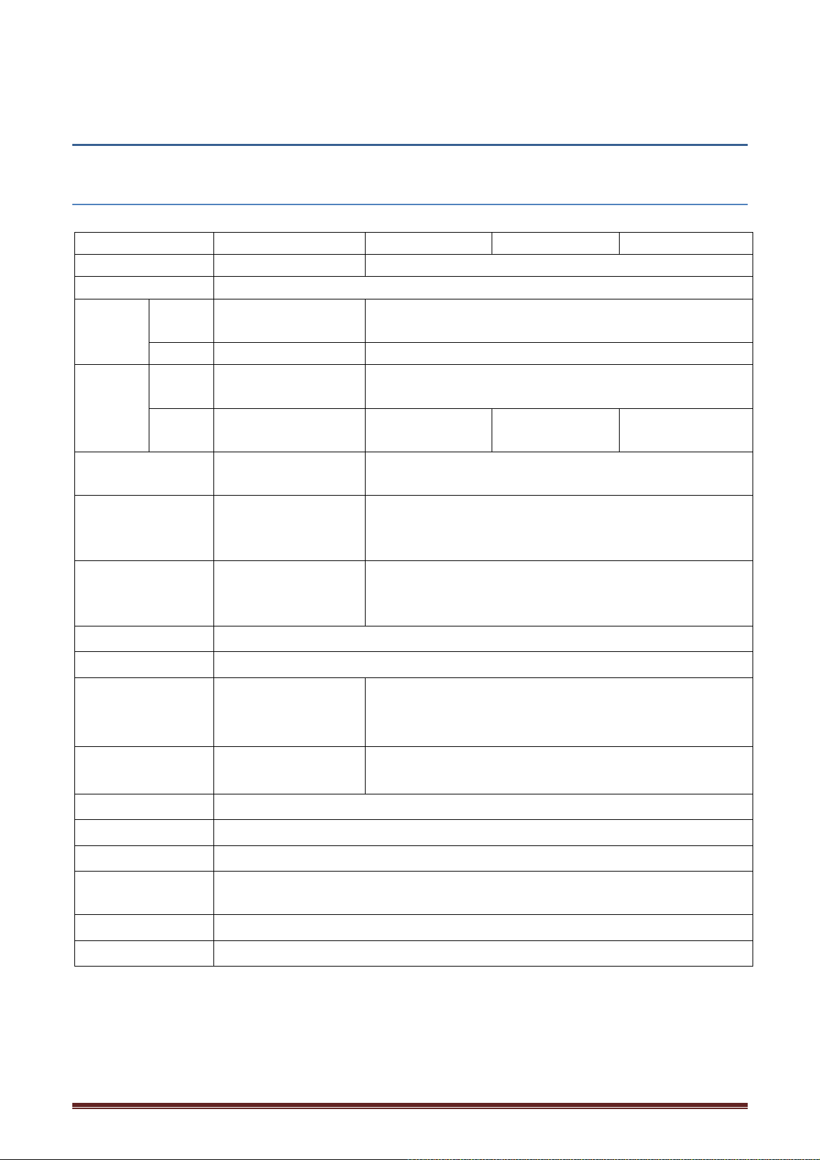
Chapter 7 Specifications
7.1 General Specifications
Model HT3554 HT3554A HT3554B HT3554D
Display 4.3" VFD display 4.3"TFT LCD Display
Measurements ESR, DCV
Resistan
ce
Voltage Accura
Signal Source AC 1kHz test
Range 3m(/30m(/300m(
Sampling Rate 1 meas/sec
Temperature
Correction
Comparator
Internal Data
Store
Trigger
Interface
Power Supply
Maximum rated
power
Dimensions
Weight
Accura
cy
Range 0.001m,~3.100, 0.001m, ~ 30.100,
cy
Range 0.0001V~60.000V 0.00001V~100.0
current: <150mA
number optional)
WARNING//FAIL/PA
Store up to 2400 set
$1% $0.5%
$0.02% $0.02%
0.00001V~300.0
00V
AC 1kHz open circuit voltage: <5VTest current <150mA
3m(/30m(/300m(/3(/30(;
/3(;
4 ranges in all
(the average
Range:-10#C ~60#C Accuracy:$1#C
200set
SS sorting
Store up to 2400 set test data (upgradable to 4800 set)
data
USB, EXPORT (port execute the hold function)
12V/2500mAh Lithium battery or AA (LR6) Alkaline batteries x8
(L) 208 x (W)120 x (D)52.5mm without sleeve
Auto and manual test mode in 5-level range
20 meas/sec, 3 meas/sec
Short circuit test for all ranges
200set Storage data
Internal/auto trigger
4VA
0.81kg
00V
0.00001V~1000.0
00V
47
Page 48
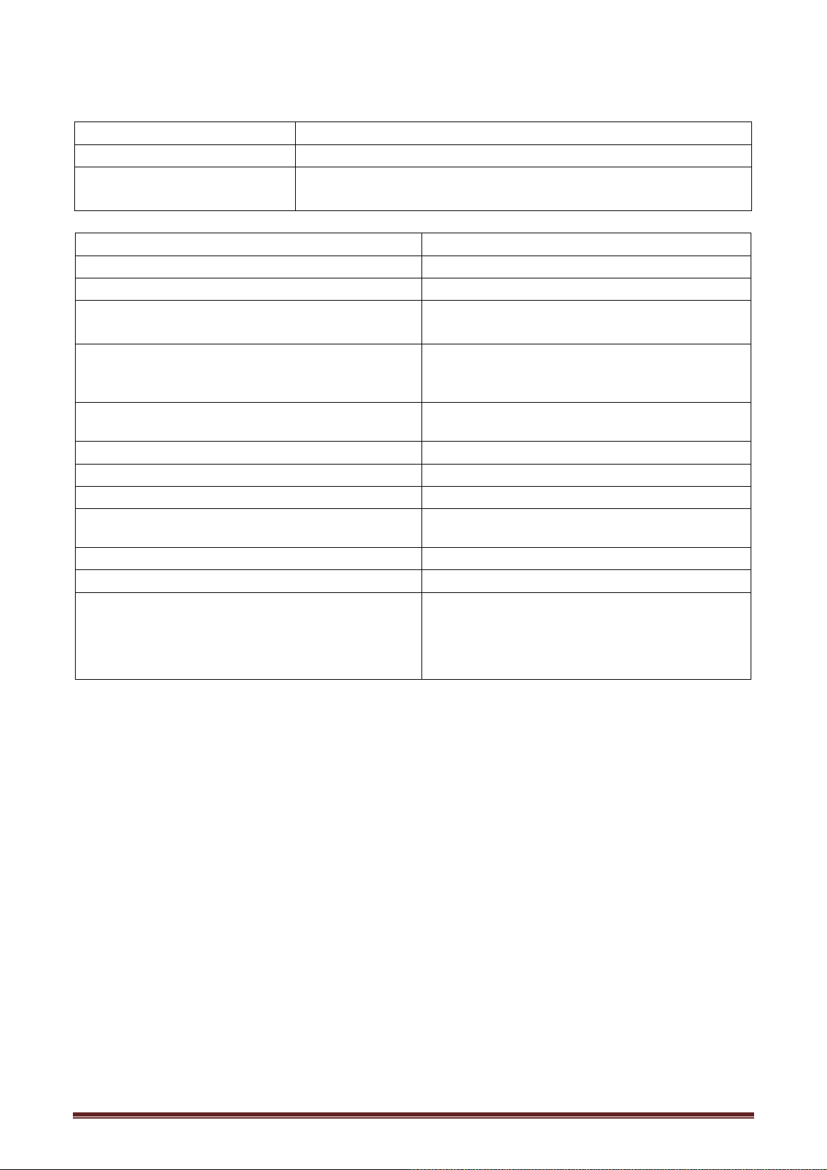
Timer
Feature 24-hour clock; leap years are adjusted automatically
Accuracy About $4 min per month.
Other
Built-in backup lithium battery
Battery life: about 2 years
Operation keys Plastic keys
Display LCD screen
Accuracy guarantee 1 year
Operating temperature and humidity
80%RH (no condensation)
0#C to 40#C
Storage temperature and humidity
80%RH (no condensation)
-10#C to 60#C
Operating environment Indoor, maximum altitude 2000 M
Power lithium battery 2500 mAh
Voltage 12V
Maximum rated power 4VA
Continuous working hours about 8 hours
Size about 205x110x55
Weight about 810g
DC 70V(HT3554)
Maximum input voltage Positive and negative
test terminals:
DC 100V(HT3554A)
DC 300V(HT3554B)
DC 1000V(HT3554D)
48
Page 49
Chapter 8 Maintenance and Service
key
8.1 Repair, Inspection, Cleaning
Customers are not allowed to modify, disassemble, or repair the instrument. Doing so may cause
fire, electric shock, or injury.
When the instrument is being repaired, batteries and parts should be removed to prevent
damage during transportation. Add gasket material to prevent the instrument from moving in the
box. Try to clarify in detail the problems encountered. The company is not responsible for
damages that occur during transportation.
Before Returning for Repair
If the instrument is not operating correctly, check the following:
Error Cause and Solution
Nothing is displayed on the
screen even after the POWER
is pressed.
Incorrect measurement values
are displayed
[''''] is displayed on the screen
[OF] is displayed on the screen
Pressing the ( or V key has no
effect.
The battery is drained.
* Charge the battery
The batteries are inserted incorrectly.
* C Reinsert the batteries correctly
The test lead is not connected correctly.
* Connect the test lead correctly.
The test lead is disconnected.
* Replace with a new test lead.
Zero adjustment is not performed correctly.
* Perform zero adjustment correctly
An appropriate range is not selected.
* Select the appropriate range using the range key.
The comparator function is turned on.
* Use the COMP key to turn off the comparator
function.
Pressing the MEMO key has no
effect.
Nothing is displayed on the
screen even after the READ key is
pressed.
The comparison result of the
comparator is not correct.
49
The data is not retained
This key cannot be used when no data has been stored.
The comparator threshold values are not set correctly.
* Use the HOLD key to retain the data.
* Set the correct threshold values.
Page 50

Chapter 9 Appendix
9.1 Effect of extended test line and induced voltage
Test lines can usually be extended by customization. If you want to extend the test line, please
contact the dealer or Hope Instrument. The user can not extend the test line privately.
Reduce induction voltage
Because the instrument under AC power to test resistance with very small resistance, the inductive
voltage will affect the test. The inductive voltage makes the current in the instrument produce
inductive coupling inside the wire, which will affect the in-line signal. Because the AC current
(reference signal) is 90 degrees different from the phase of the induced voltage, the synchronous
detector circuit can remove the induced voltage when the voltage is low. But when the voltage is
high, the inductive voltage will distort the signal and produce the wrong synchronous detection
signal. The instrument detects the internal inductive voltage, if the voltage rises to a certain height,
will produce the wrong test signal. Reducing the length of the test line, especially the length of the
branch part, will weaken the inductive voltage. When the standard test line is used, the induced
voltage will affect the deviation of the result value by about 15 dgt.. if the zero adjustment
and the test wiring are extremely different in 3 mΩ range.
9.2 Influence of Eddy Current
The AC current in the instrument will generate eddy current around the metal plate, and the
eddy current will generate inductive voltage inside the test line. Because the phase of the
induced voltage is 180 degrees different from the phase of the AC current (reference current),
the synchronous detection current cannot eliminate the induced voltage, which leads to a test
error. Eddy effect is unique to the ohmmeter of AC power supply. The distance between the
metal parts including the metal plate and the test line (branch part) should be reduced to avoid
the influence of eddy current.
50
Page 51
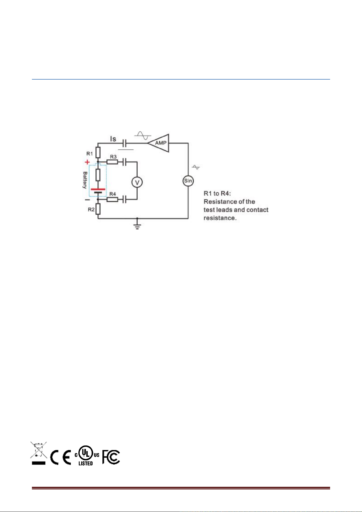
9.3 AC 4-terminal Measurement Method
The instrument uses AC four-terminal measurement method, so when measuring resistance,
it is not necessary to consider the internal resistance of the test line and the contact
resistance between the test line and the object under test.
The AC current (Is) flowing from the SOURCE port of the instrument flows through the
tested battery. The voltage drop (VIS) of the internal resistance of the battery is measured
by the SENSE port. At this point, since the SENSE port is connected to an internal voltmeter
with a high impedance, there is no current passing on the R2 and R3 representing the
resistance and contact resistance in the test line. Therefore, there is no voltage drop on
the resistance R2 and R3, because the voltage drop of the resistance and contact
resistance in the test line is very small, which can be ignored. In the instrument, using a
synchronous detection system, the internal resistance is divided into impedance and
reactance, showing only the actual part.
if the resistance within the test line, the contact resistance between the object under test
and the test line or the contact resistance between the test line and the instrument
increases, then the instrument will be supplied to the abnormal current of the object
under test, which will cause the test state error, showing the "------" symbol where the
resistance is tested.
INFORMATION ON WASTE DISPOSAL FOR CONSUMERS OF ELECTRICAL & ELECTRONIC EQUIPMENT.
When this product has reached the end of its life it must be treated as Waste Electrical & Electronics
Equipment (WEEE). Any WEEE marked products must not be mixed with general household waste, but
kept separate for the treatment, recovery and recycling of the materials used. Contact your local authority
for details of recycling schemes in your area.
Made in China
LS12 2QQ
51
 Loading...