

Page 1
Page 1
RF65
Tel: +86-755-82973805 Fax: +86-755-82973550 E-mail: [email protected] http://www.hoperf.com
Part Number
Delivery
MOQ / Multiple
RF65
Tape & Reel
3000 pieces
Decimation and
&
Filtering
Demodulator &
Bit
Synchronizer
Packet Engine
& 66 Bytes
FIFO
Control Registers
- Shift
Registers
- SPI
Interface
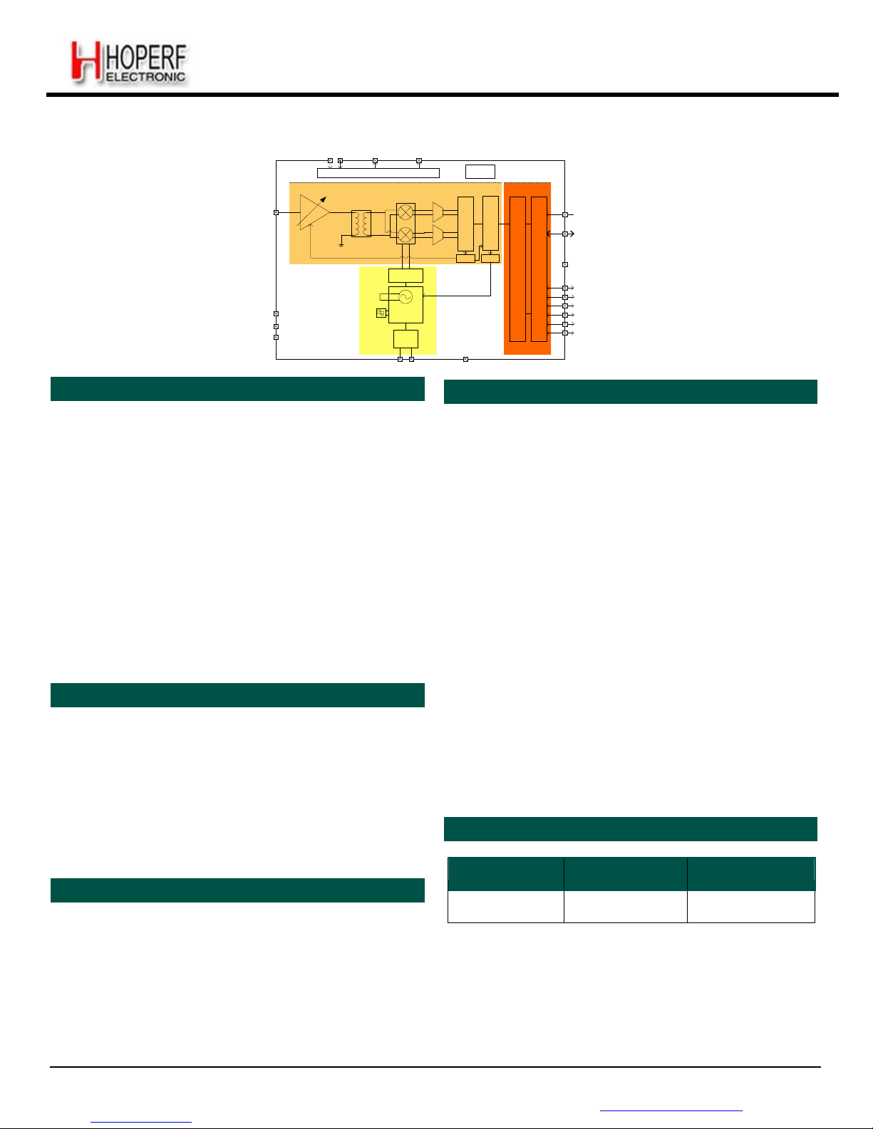
Low Power Integrated UHF Receiver With -120dBm High Sensitivity
VBAT1&2 VR_ANA VR_DIG
Power
Distribution System
RC
Oscillator
RFIN
LNA
Single to
Differential
Mixers
Σ/
Δ
Modulators
RESET
SPI
Division by
2, 4 or 6
RSSI
AFC
GND
Tank
I
nductor
Loop
NC
Filter
NC
NC
Frac-N PLL
Synthesizer
XO
32
MHz
DIO0
DIO1
DIO2
DIO3
DIO4
DIO5
GENERAL DESCRIPTION
XTAL
GND
KEY PRODUCT FEATURES
The RF65 is a highly integrated RF receiver capable of
operation over a wide frequency range, including the
315,433,868 and 915 MHz license-free ISM (Industry
Scientific and Medical) frequency bands. Its highly
integrated architecture allows for a minimum of external
components whilst maintaining maximum design flexibility.
All major RF communication parameters are programmable
and most of them can be dynamically set. The RF65 offers
the unique advantage of programmable narrow-band and
wide-band communication modes without the need to
modify external components. The RF65 is optimized for
low power consumption while offering high sensitivity and
channelized operation. TrueRF™ technology enables a
lowcost external component count (elimination of the SAW
filter) whilst still satisfying ETSI and FCC regulations.
APPLICATIONS
Automated Meter Reading
Wireless Sensor Networks
Home and Building Automation
Wireless Alarm and Security Systems
Industrial Monitoring and Control
High Sensitivity: down to -120 dBm at 1.2 kbps
High Selectivity: 16-tap FIR Channel Filter
Bullet-proof front end: IIP3 = -18 dBm, IIP2 = +35 dBm,
80 dB Blocking Immunity, no Image Frequency response
Low current: Rx = 16 mA, 100nA register retention
Constant RF performance over voltage range of chip
FSK Bit rates up to 300 kb/s
Fully integrated synthesizer with a resolution of 61 Hz
FSK, GFSK, MSK, GMSK and OOK demodulation
Built-in Bit Synchronizer performing Clock Recovery
Incoming Sync Word Recognition
115 dB+ Dynamic Range RSSI
Automatic RF Sense with ultra-fast AFC
Packet engine with CRC, AES-128 encryption and 66-
byte FIFO
Built-in temperature sensor and Low Battery indicator
ORDERING INFORMATION
MARKETS
Europe: EN 300-220-1
North America: FCC Part 15.247, 15.249,
15.231
Narrow Korean and Japanese bands
QFN 28 Package - Operating Range [-40;+85°C]
Pb-free, Halogen free, RoHS/WEEE compliant product
Page 2

Page 2
RF65
Tel: +86-755-82973805 Fax: +86-755-82973550 E-mail: [email protected] http://www.hoperf.com
3.4.15.
Frequency Error Indicator.......................................................................................................................
26
3.4.16.
Automatic Frequency
Correction
............................................................................................................
27
3.4.17.
Optimized Setup for Low Modulation Index
Systems
.............................................................................
28
ADVANCED COMMUNICATIONS & SENSING DATASHEET
Table of Contents
Page
1. General
Description .................................................................................................................................................
8
1.1. Simplified Block
Diagram
.................................................................................................................................8
1.2. Pin and Marking
Diagram................................................................................................................................... 9
1.3. Pin
Description
......................................................................................................................................10
2. Electrical
Characteristics..........................................................................................................................................
11
2.1. ESD
Notice....................................................................................................................................................... 11
2.2. Absolute Maximum Ratings ...................................................................................................................11
2.3. Operating
Range.............................................................................................................................................. 11
2.4. Chip Specification ................................................................................................................................ 12
2.4.1. Power
Consumption
................................................................................................................................. 12
2.4.2. Frequency
Synthesis
................................................................................................................................ 12
2.4.3. Receiver
.....................................................................................................................................................
13
2.4.4. Digital
Specification
.................................................................................................................................. 14
3. Chip
Description......................................................................................................................................................
15
3.1. Power Supply
Strategy..................................................................................................................................... 15
3.2. Low Battery
Detector........................................................................................................................................ 15
3.3. Frequency
Synthesis........................................................................................................................................ 15
3.3.1. Reference
Oscillator
................................................................................................................................. 15
3.3.2. CLKOUT Output .......................................................................................................................................16
3.3.3. PLL
Architecture
....................................................................................................................................... .16
3.3.4. Lock Time .................................................................................................................................................17
3.3.5. Lock Detect Indicator................................................................................................................................. 17
3.4. Receiver
Description
...............................................................................................................................17
3.4.1. Block
Diagram
........................................................................................................................................... 17
3.4.2. LNA - Single to Differential Buffer .............................................................................................................18
3.4.3. Automatic Gain Control ............................................................................................................................. 18
3.4.4. Continuous-Time DAGC............................................................................................................................ 20
3.4.5. Quadrature Mixer - ADCs - Decimators..................................................................................................... 20
3.4.6. Channel
Filter
............................................................................................................................................20
3.4.7. DC Cancellation ........................................................................................................................................21
3.4.8. Complex Filter -
OOK
................................................................................................................................22
3.4.9.
RSSI ............................................................................................................................................................
22
3.4.10.
Cordic .......................... ..............................................................................................................................
22
3.4.11. Bit Rate Setting .......................................................................................................................................22
3.4.12. FSK
Demodulator
....................................................................................................................................23
3.4.13. OOK Demodulator ..................................................................................................................................24
3.4.14. Bit Synchronizer .................................................................................................................................... 26
Page 3

Page 3
RF65
Tel: +86-755-82973805 Fax: +86-755-82973550 E-mail: [email protected] http://www.hoperf.com
5.4.1. General Description..................................................................................................................................
43
5.4.2. Rx Processing ..........................................................................................................................................
43
5.5. Packet
Mode
.................................................................................................................................................
44
5.5.1.
General Description..................................................................................................................................
44
5.5.2.
Packet
Format
..........................................................................................................................................
44
5.5.3.
Processing (without AES).........................................................................................................................
47
5.5.4.
AES ..........................................................................................................................................................
47
5.5.5.
Handling Large Packets ...........................................................................................................................
48
5.5.6.
Packet Filtering.........................................................................................................................................
48
5.5.7.
DC-Free Data
Mechanisms
......................................................................................................................
50
Configuration and Status
Registers
...................................................................................................................... 52
6.1.
General Description ......................................................................................................................................
52
6.2.
Common Configuration
Registers
.................................................................................................................
55
6.3.
Receiver Registers ........................................................................................................................................
58
ADVANCED COMMUNICATIONS & SENSING DATASHEET
3.4.18. Temperature Sensor ............................................................................................................................29
3.4.19. Timeout
Function....................................................................................................................................
29
4. Operating Modes
..................................................................................................................................................
30
4.1. Basic
Modes..................................................................................................................................................
30
4.2. Automatic Sequencer and Wake-Up
Times
.................................................................................................30
4.2.1. Receiver Startup Time.............................................................................................................................30
4.2.2. Rx Start
Procedure
..................................................................................................................................32
4.2.3. Optimized Frequency Hopping
Sequences
..............................................................................................32
4.3. Listen Mode
...................................................................................................................................................
33
4.3.1.
Timings .......................... ...........................................................................................................................
33
4.3.2.
Criteria ......................................................................................................................................................
34
4.3.3. End of Cycle Actions ............................................................................................................................... 34
4.3.4. RC Timer Accuracy ..................................................................................................................................35
4.4. AutoModes
.................................................................................................................................................... .
36
5. Data
Processing.................................................................................................................................................... .
37
5.1.
Overview .........................................................................................................................................................
37
5.1.1. Block
Diagram
..........................................................................................................................................37
5.1.2. Data Operation Modes .............................................................................................................................37
5.2. Control Block
Description
.............................................................................................................................. 38
5.2.1. SPI
Interface..............................................................................................................................................
38
5.2.2. FIFO
..........................................................................................................................................................
39
5.2.3. Sync Word
Recognition
............................................................................................................................ 40
5.2.4. Packet
Handler
......................................................................................................................................... 41
5.2.5.
Control ........................................................................................................................................................
41
5.3. Digital IO Pins Mapping
...................................................................................................................................
42
5.3.1. DIO Pins Mapping in Continuous Mode ................................................................................................... 42
5.3.2. DIO Pins Mapping in Packet Mode .......................................................................................................... 42
5.4. Continuous Mode
............................................................................................................................................
43
6.
Page 4

Page 4
RF65
Tel: +86-755-82973805 Fax: +86-755-82973550 E-mail: [email protected] http://www.hoperf.com
8.1.
Package Outline Drawing..............................................................................................................................
69
8.2.
Thermal Impedance ......................................................................................................................................
69
9. Chip
Revisions ........................................................................................................................................................
70
9.1. RC Oscillator Calibration...............................................................................................................................
70
9.2. Listen Mode...................................................................................................................................................
70
9.2.1. Resolutions...............................................................................................................................................
70
9.2.2. Exiting Listen
Mode
..................................................................................................................................
71
9.3. OOK Floor Threshold Default Setting ...........................................................................................................
71
9.4. AFC Control ..................................................................................................................................................
71
9.4.1. AfcAutoClearOn .......................................................................................................................................
71
9.4.2. AfcLowBetaOn and LowBetaAfcOffset.....................................................................................................
71
9.5. ContinuousDagc............................................................................................................................................
71
ADVANCED COMMUNICATIONS & SENSING DATASHEET
6.4.
IRQ and Pin Mapping Registers ....................................................................................................................
60
6.5.
Packet Engine
Registers
...............................................................................................................................
62
6.6.
Temperature Sensor
Registers
.....................................................................................................................
65
6.7.
Test
Registers
...............................................................................................................................................
65
7. Application Information ......................................................................................................................................... 66
7.1.
Crystal Resonator
Specification
....................................................................................................................
66
7.2.
Reset of the Chip ..........................................................................................................................................
66
7.2.1.
POR............................................................................................................................................................
66
7.2.2. Manual Reset ...........................................................................................................................................67
7.3. Reference Design ......................................................................................................................................... 67
8. Packaging
Information
...........................................................................................................................................69
Page 5

Page 5
RF65
Tel: +86-755-82973805 Fax: +86-755-82973550 E-mail: [email protected] http://www.hoperf.com
ADVANCED COMMUNICATIONS & SENSING DATASHEET
Index of Figures Page
Figure 1. Block Diagram
................................................................................................................ ................................
8
Figure 2. Pin Diagram
.................................................................................................................... ................................
9
Figure 3. Marking Diagram
............................................................................................................................................
9
Figure 4. TCXO Connection
........................................................................................................................................
15
Figure 5. Receiver Block Diagram
...............................................................................................................................
17
Figure 6. AGC Thresholds Settings
.............................................................................................................................
19
Figure 7. Cordic Extraction
..........................................................................................................................................
22
Figure 8. OOK Peak Demodulator Description
............................................................................................................
24
Figure 9. Floor Threshold Optimization
.......................................................................................................................
25
Figure 10. Bit Synchronizer Description
......................................................................................................................
26
Figure 11. FEI Process
................................................................................................................................................
27
Figure 12. Optimized Afc (AfcLowBetaOn=1)
..............................................................................................................
28
Figure 13. Temperature Sensor Response
.................................................................................................................
29
Figure 14. Rx Startup - No AGC, no AFC
....................................................................................................................
31
Figure 15. Rx Startup - AGC, no AFC
.........................................................................................................................
31
Figure 16. Rx Startup - AGC and AFC
........................................................................................................................
31
Figure 17. Listen Mode Sequence (no wanted signal is received)
..............................................................................
33
Figure 18. Listen Mode Sequence (wanted signal is received)
...................................................................................
35
Figure 19. Auto Modes of Packet Handler
...................................................................................................................
36
Figure 20. RF65 Data Processing Conceptual View
...................................................................................................
37
Figure 21. SPI Timing Diagram (single access)
..........................................................................................................
38
Figure 22. FIFO and Shift Register (SR)
.....................................................................................................................
39
Figure 23. FifoLevel IRQ Source Behavior
..................................................................................................................
40
Figure 24. Sync Word Recognition
..............................................................................................................................
41
Figure 25. Continuous Mode Conceptual View
............................................................................. ..............................
43
Figure 26. Rx Processing in Continuous Mode
............................................................................. ..............................
43
Figure 27. Packet Mode Conceptual View
...................................................................................................................
44
Figure 28. Fixed Length Packet Format
......................................................................................................................
45
Figure 29. Variable Length Packet Format
..................................................................................................................
46
Figure 30. Unlimited Length Packet Format
................................................................................................................
46
Figure 31. CRC Implementation
.................................................................................................... ..............................
50
Figure 32. Manchester Decoding
................................................................................................................................
50
Figure 33. Data De-Whitening
.....................................................................................................................................
51
Figure 34. POR Timing Diagram
.................................................................................................................................
66
Figure 35. Manual Reset Timing Diagram
...................................................................................................................
67
Figure 36. Application Schematic
................................................................................................................................
67
Figure 37. Package Outline Drawing
...........................................................................................................................
68
Figure 38. Listen Mode Resolutions, V2a
...................................................................................................................
69
Figure 39. Listen Mode Resolution, V2b
.....................................................................................................................
69
Page 6

Page 6
RF65
Tel: +86-755-82973805 Fax: +86-755-82973550 E-mail: [email protected] http://www.hoperf.com
ADVANCED COMMUNICATIONS & SENSING DATASHEET
Figure 40. Exiting Listen Mode in RF65 V2a
...............................................................................................................
70
Figure 41. RegTestOok Description
............................................................................................................................
70
Index of Tables Page
Table 1. RF65 Pinouts
..................................................................................................................................................
10
Table 2. Absolute Maximum Ratings
............................................................................................................................
11
Table 3. Operating Range
............................................................................................................................................
11
Table 4. Power Consumption Specification
..................................................................................................................
12
Table 5. Frequency Synthesizer Specification
..............................................................................................................
12
Table 6. Receiver Specification
....................................................................................................................................
13
Table 7. Digital Specification
........................................................................................................................................
14
Table 8. LNA Gain Settings
..........................................................................................................................................
18
Table 9. Receiver Performance Summary
....................................................................................................................
19
Table 10. Available RxBw Settings
...............................................................................................................................
21
Table 11. Bit Rate Examples
........................................................................................................................................
23
Table 12. Basic Receiver Modes
..................................................................................................................................
30
Table 13. Range of Durations in Listen Mode
..............................................................................................................
33
Table 14. Signal Acceptance Criteria in Listen Mode
....................... ............................................................................
34
Table 15. End of Listen Cycle Actions
..........................................................................................................................
34
Table 16. Status of FIFO when Switching Between Different Modes of the Chip
.........................................................
40
Table 17. DIO Mapping, Continuous Mode
..................................................................................................................
42
Table 18. DIO Mapping, Packet Mode
.........................................................................................................................
42
Table 19. Registers Summary
......................................................................................................................................
52
Table 20. Common Configuration Registers
.................................................................................................................
55
Table 21. Receiver Registers
.......................................................................................................................................
58
Table 22. IRQ and Pin Mapping Registers
...................................................................................................................
60
Table 23. Packet Engine Registers
..............................................................................................................................
62
Table 24. Temperature Sensor Registers
.....................................................................................................................
65
Table 25. Test Registers
..............................................................................................................................................
65
Table 26. Crystal Specification
.....................................................................................................................................
66
Table 27. Chip Identification
.........................................................................................................................................
70
Table 28. Revision History
............................................................................................................................................
72
Page 7

Page 7
RF65
Tel: +86-755-82973805 Fax: +86-755-82973550 E-mail: [email protected] http://www.hoperf.com
ADVANCED COMMUNICATIONS & SENSING DATASHEET
Acronyms
BOM Bill Of Materials LSB Least Significant Bit
BR Bit Rate MSB Most Significant Bit
BW Bandwidth NRZ Non Return to Zero
CCITT Comité Consultatif International
Téléphonique et Télégraphique - ITU
OOK On Off Keying
CRC Cyclic Redundancy Check PA Power Amplifier
DAC Digital to Analog Converter PCB Printed Circuit Board
ETSI European Telecommunications Standards
Institute
PLL Phase-Locked Loop
FCC Federal Communications Commission POR Power On Reset
Fdev Frequency Deviation RBW Resolution BandWidth
FIFO First In First Out RF Radio Frequency
FIR Finite Impulse Response RSSI Received Signal Strength Indicator
FS Frequency Synthesizer Rx Receiver
FSK Frequency Shift Keying SAW Surface Acoustic Wave
GUI Graphical User Interface SPI Serial Peripheral Interface
IC Integrated Circuit SR Shift Register
ID IDentificator Stby Standby
IF Intermediate Frequency Tx Transmitter
IRQ Interrupt ReQuest uC Microcontroller
ITU International Telecommunication Union VCO Voltage Controlled Oscillator
LFSR Linear Feedback Shift Register XO Crystal Oscillator
LNA Low Noise Amplifier XOR eXclusive OR
LO Local Oscillator
Page 8
Page 8
RF65
Tel: +86-755-82973805 Fax: +86-755-82973550 E-mail: [email protected] http://www.hoperf.com
Decimation and
& Filtering
Demodulator &
Bit Synchronizer
Packet Engine & 66 Bytes FIFO
Control Registers - Shift Registers - SPI Interface
ADVANCED COMMUNICATIONS & SENSING DATASHEET
This product datasheet contains a detailed description of the RF65 performance and functionality.
.
1. General Description
The RF65 is a single-chip integrated circuit ideally suited for today's high performance ISM band RF applications. The
RF65's advanced features set, including state of the art packet engine greatly simplifies system design whilst the high
level of integration reduces the external BOM to a handful of passive decoupling and matching components. It is intended
for use as high-performance, low-cost FSK and OOK RF receiver for robust frequency agile RF links, and where stable
and constant RF performance is required over the full operating range of the device down to 1.8V.
The RF65 is intended for applications over a wide frequency range, including the 433 MHz and 868 MHz European and
the 902-928 MHz North American ISM bands. Coupled with a very aggressive sensitivity, the advanced system features of
the RF65 include a 66 byte RX FIFO, configurable automatic packet handler, listen mode, temperature sensor and
configurable DIOs which greatly enhance system flexibility whilst at the same time significantly reducing MCU
requirements.
The RF65 complies with both ETSI and FCC regulatory requirements and is available in a 5 x 5 mm QFN 28 lead
package
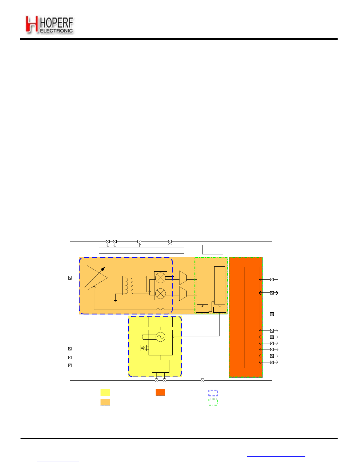
1.1. Simplified Block Diagram
VBAT1&2 VR_ANA VR_DIG
Power Distribution System
RC
Oscillator
LNA
Single to
Differential
Mixers
Σ/Δ
Modulators
RFIN
RESET
SPI
Tank
Inductor
Loop
NC
Filter
NC
NC
Division by
2, 4 or 6
Frac-N PLL
Synthesizer
XO
32 MHz
RSSI AFC
GND
DIO0
DIO1
DIO2
DIO3
DIO4
DIO5
Frequency Synthesis
Receiver Blocks
XTAL GND
Control Blocks
Primarily Analog
Primarily Digital
Figure 1. Block
Diagram
Page 9
Page 9
RF65
Tel: +86-755-82973805 Fax: +86-755-82973550 E-mail: [email protected] http://www.hoperf.com
ADVANCED COMMUNICATIONS & SENSING DATASHEET
1.2. Pin and Marking Diagram
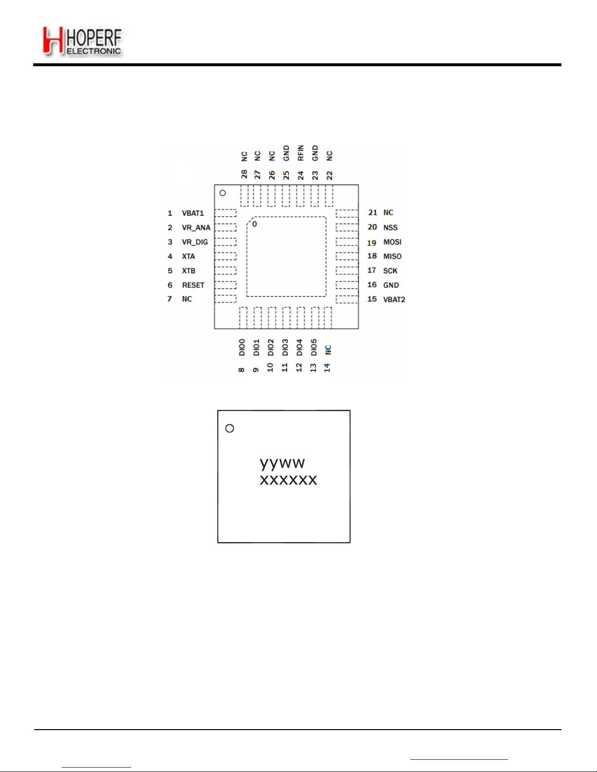
The following diagram shows the pin arrangement of the QFN package, top view.
Figure 2. Pin
Diagram
Notes yyww refers to the date code
xxxxxx refers to the lot number
Figure 3. Marking Diagram
RF65
Page 10
Page 10
RF65
Tel: +86-755-82973805 Fax: +86-755-82973550 E-mail: [email protected] http://www.hoperf.com
ADVANCED COMMUNICATIONS & SENSING DATASHEET
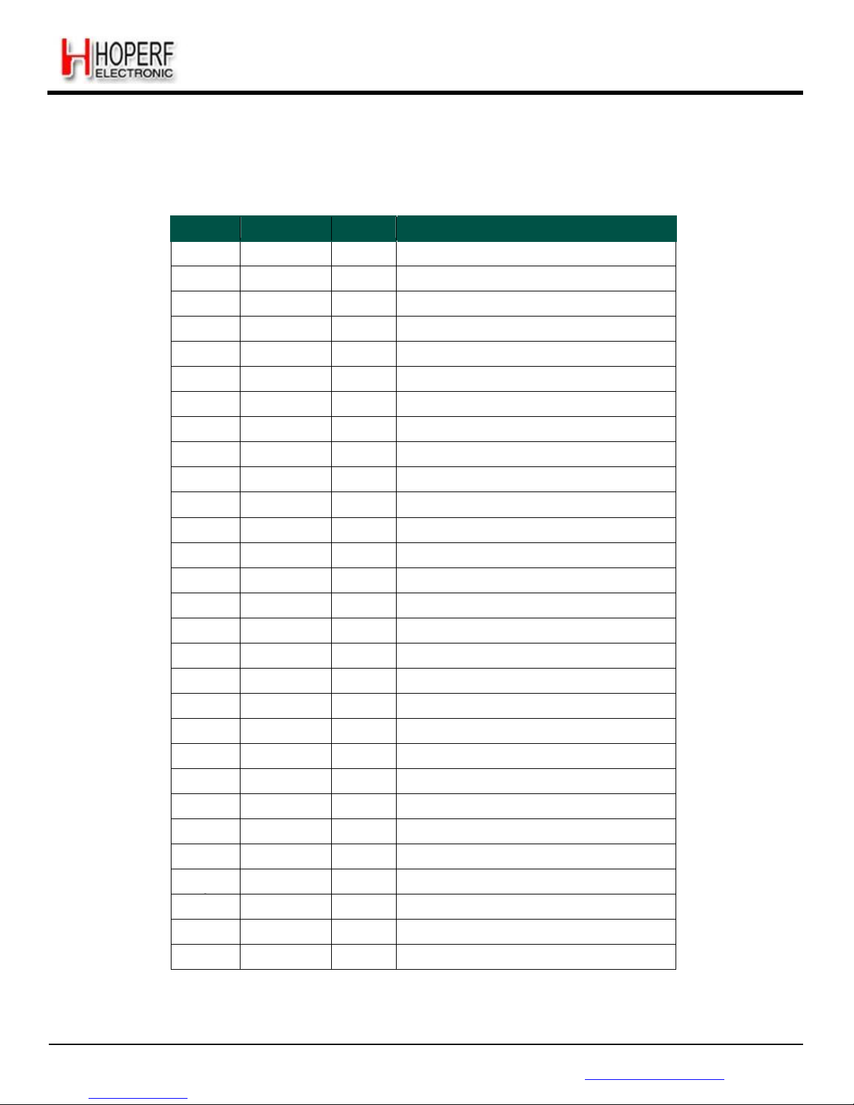
1.3. Pin Description
Table 1 RF65 Pinouts
Number
Name
Type
Description
0
GROUND
-
Exposed ground pad
1
VBAT1
-
Supply voltage
2
VR_ANA
-
Regulated supply voltage for analogue circuitry
3
VR_DIG
-
Regulated supply voltage for digital blocks
4
XTA
I/O
XTAL connection
5
XTB
I/O
XTAL connection
6
RESET
I/O
Reset trigger input
7
NC
-
Connect to GND or Do not connect
8
DIO0
I/O
Digital I/O, software configured
9
DIO1/DCLK
O
Digital Output, software configured
10
DIO2/DATA
O
Digital Output, software configured
11
DIO3
I/O
Digital I/O, software configured
12
DIO4
I/O
Digital I/O, software configured
13
DIO5
I/O
Digital I/O, software configured
14
NC
-
Connect to GND or Do not connect
15
VBAT2
-
Supply voltage
16
GND
-
Ground
17
SCK
I
SPI Clock input
18
MISO
O
SPI Data output
19
MOSI
I
SPI Data input
20
NSS
I
SPI Chip select input
21
NC
-
Connect to GND or Do not connect
22
NC
-
Do not connect
23
GND
-
Ground
24
RFIN
I
RF input
25 GND
-
Ground
26
NC
-
Do not connect
27
NC
-
Do not connect
28
NC
-
Connect to GND or Do not connect
Page 11
Page 11
RF65
Tel: +86-755-82973805 Fax: +86-755-82973550 E-mail: [email protected] http://www.hoperf.com
ADVANCED COMMUNICATIONS & SENSING DATASHEET
2. Electrical Characteristics
2.1. ESD Notice
The RF65 is a high performance radio frequency device.
Class 2 of the JEDEC standard JESD22-A114-B (Human Body Model) on all pins.
Class B of the JEDEC standard JESD22-A115-A (Machine Model) on all pins.
Class IV of the JEDEC standard JESD22-C101C (Charged Device Model) on pins 2-3-24-26-27, Class III on all other pins.
It should thus be handled with all the necessary ESD precautions to avoid any permanent damage.
2.2. Absolute Maximum Ratings
Stresses above the values listed below may cause permanent device failure. Exposure to absolute maximum ratings for
extended periods may affect device reliability.
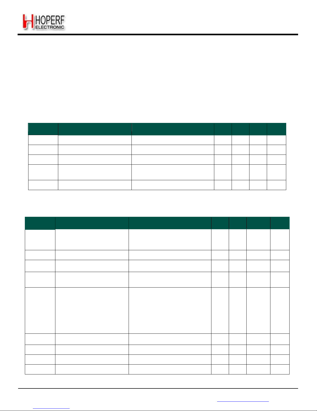
Table 2 Absolute Maximum Ratings
Symbol
Description
Min
Max
Unit
VDDmr
Supply Voltage
-0.5
3.9
V
Tmr
Temperature
-55
+115
° C
Tj
Junction temperature
-
+125
° C
Pmr
RF Input Level
-
+6
dBm
2.3. Operating Range
Table 3 Operating Range
Symbol
Description
Min
Max
Unit
VDDop
Supply voltage
1.8
3.6
V
Top
Operational temperature range
-40
+85
°C
Clop
Load capacitance on digital ports
-
25
pF
ML
RF Input Level
-
0
dBm
Page 12
Page 12
RF65
Tel: +86-755-82973805 Fax: +86-755-82973550 E-mail: [email protected] http://www.hoperf.com
ADVANCED COMMUNICATIONS & SENSING DATASHEET
2.4. Chip Specification
The tables below give the electrical specifications of the receiver under the following conditions: Supply voltage VBAT1=
VBAT2=VDD=3.3 V, temperature = 25 °C, FXOSC = 32 MHz, F
RF
= 915 MHz, 2-level FSK modulation without pre-filtering,
Bit Rate = 4.8 kb/s and terminated in a matched 50 Ohm impedance, unless otherwise specified.
Note Unless otherwise specified, the performances in the other frequency bands are similar or better.
2.4.1. Power Consumption
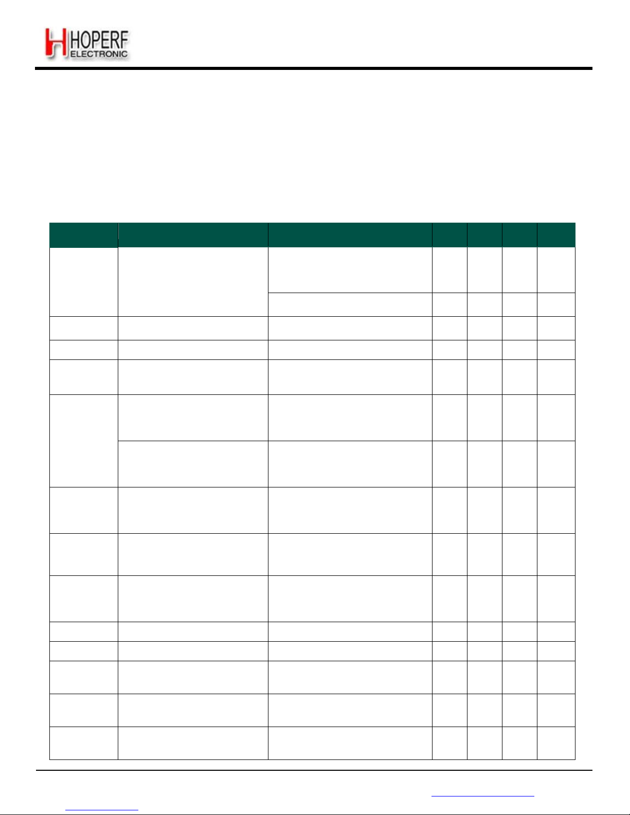
Table 4 Power Consumption Specification
Symbol
Description
Conditions
Min
Typ
Max
Unit
IDDSL
Supply current in sleep mode
-
0.1
1
uA
IDDIDLE
Supply current in Idle mode
RC oscillator enabled
-
1.2
-
uA
IDDST
Supply current in standby mode
Crystal oscillator enabled
-
1.25
1.5
mA
IDDFS
Supply current in synthesizer
mode
- 9 -
mA
IDDR
Supply current in receive mode
-
16 - mA
2.4.2. Frequency Synthesis
Table 5 Frequency Synthesizer Specification
Symbol
Description
Conditions
Min
Typ
Max
Unit
FR
Synthesizer Frequency Range
Programmable
290
424
862
-
-
-
340
510
1020
MHz
MHz
MHz
FXOSC
Crystal oscillator frequency
See section 7.1
-
32 - MHz
TS_OSC
Crystal oscillator wake-up time
-
250
500
us
TS_FS
Frequency synthesizer wake-up
time to PllLock signal
From Standby mode
-
80
150
us
TS_HOP
Frequency synthesizer hop time
at most 10 kHz away from the
target
200 kHz step
1 MHz step
5 MHz step
7 MHz step
12 MHz step
20 MHz step
25 MHz step
-
-
-
-
-
-
-
20
20
50
50
80
80
80
-
-
-
-
-
-
-
us
us
us
us
us
us
us
FSTEP
Frequency synthesizer step
FSTEP = FXOSC/2
19
-
61.0
-
Hz
FRC
RC Oscillator frequency
After calibration
-
62.5
-
kHz
BRF
Bit rate, FSK
Programmable
1.2 - 300
kbps
BRO
Bit rate, OOK
Programmable
1.2 - 32.768
kbps
Page 13
Page 13
RF65
Tel: +86-755-82973805 Fax: +86-755-82973550 E-mail: [email protected] http://www.hoperf.com
ADVANCED COMMUNICATIONS & SENSING DATASHEET
2.4.3. Receiver
All receiver tests are performed with RxBw = 10 kHz (Single Side Bandwidth) as programmed in RegRxBw, receiving a
PN15 sequence with a BER of 0.1% (Bit Synchronizer is enabled), unless otherwise specified. The LNA impedance is set
to 200 Ohms, by setting bit LnaZin in RegLna to 1. Blocking tests are performed with an unmodulated interferer. The
wanted signal power for the Blocking Immunity, ACR, IIP2, IIP3 and AMR tests is set 3 dB above the nominal sensitivity
level.
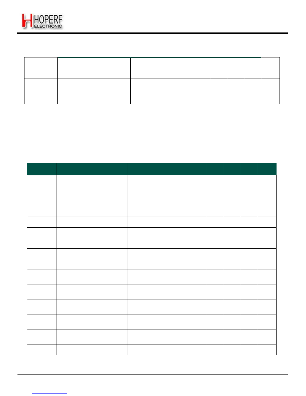
Table 6 Receiver Specification
Symbol
Description
Conditions
Min Typ Max Unit
RFS_F
FSK sensitivity, highest LNA gain
FDA = 5 kHz, BR = 1.2 kb/s
FDA = 5 kHz, BR = 4.8 kb/s
FDA = 40 kHz, BR = 38.4 kb/s
-
-
-
-118
-114
-105
-
-
-
dBm
dBm
dBm
FDA = 5 kHz, BR = 1.2 kb/s*
-
-120
-
dBm
RFS_O
OOK sensitivity, highest LNA gain
BR = 4.8 kb/s
-
-112
-109
dBm
CCR
Co-Channel Rejection
-13
-10
-
dB
ACR
Adjacent Channel Rejection
Offset = +/- 25 kHz
Offset = +/- 50 kHz
-
37
42
42 - -
dB
dB
BI
Blocking Immunity
Offset = +/- 1 MHz
Offset = +/- 2 MHz
Offset = +/- 10 MHz
-
-
-
-45
-40
-32
-
-
-
dBm
dBm
dBm
Blocking Immunity
Wanted signal at sensitivity
+16dB
Offset = +/- 1 MHz
Offset = +/- 2 MHz
Offset = +/- 10 MHz
-
-
-
-36
-33
-25
-
-
-
dBm
dBm
dBm
AMR
AM Rejection , AM modulated
interferer with 100% modulation
depth, fm = 1 kHz, square
Offset = +/- 1 MHz
Offset = +/- 2 MHz
Offset = +/- 10 MHz
-
-
-
-45
-40
-32
-
-
-
dBm
dBm
dBm
IIP2
2nd order Input Intercept Point
Unwanted tones are 20 MHz
above the LO
Lowest LNA gain
Highest LNA gain
- - +75
+35 - -
dBm
dBm
IIP3
3rd order Input Intercept point
Unwanted tones are 1MHz and
1.995 MHz above the LO
Lowest LNA gain
Highest LNA gain
-
-23
+20
-18 - -
dBm
dBm
BW_SSB
Single Side channel filter BW
Programmable
2.6 - 500
kHz
IMR_OOK
Image rejection in OOK mode
Wanted signal level = -106 dBm
27
30 - dB
TS_RE
Receiver wake-up time, from PLL
locked state to RxReady
RxBw = 10 kHz, BR = 4.8 kb/s
RxBw = 200 kHz, BR = 100 kb/s
- - 1.7
96 - -
ms
us
TS_RE_AGC
Receiver wake-up time, from PLL
locked state, AGC enabled
RxBw= 10 kHz, BR = 4.8 kb/s
RxBw = 200 kHz, BR = 100 kb/s
-
3.0
163
ms
us
TS_RE_AGC
&AFC
Receiver wake-up time, from PLL
lock state, AGC and AFC enabled
RxBw= 10 kHz, BR = 4.8 kb/s
RxBw = 200 kHz, BR = 100 kb/s
4.8
265
ms
us
Page 14
Page 14
RF65
Tel: +86-755-82973805 Fax: +86-755-82973550 E-mail: [email protected] http://www.hoperf.com
ADVANCED COMMUNICATIONS & SENSING DATASHEET
TS_FEI
FEI sampling time
Receiver is ready
-
4.T
bit
-
-
TS_AFC
AFC Response Time
Receiver is ready
-
4.T
bit
-
-
TS_RSSI
RSSI Response Time
Receiver is ready
-
2.T
bit
-
-
DR_RSSI
RSSI Dynamic Range
AGC enabled Min
Max
- - -115 0 - - dBm
dBm
* Set SensitivityBoost in RegTestLna to 0x2D to reduce the noise floor in the receiver
2.4.4. Digital Specification
Conditions: Temp = 25°C, VDD = 3.3V, FXOSC = 32 MHz, unless otherwise specified.
Table 7 Digital Specification
Symbol
Description
Conditions
Min
Typ
Max
Unit
V
IH
Digital input level high
0.8 - -
VDD
V
IL
Digital input level low
- - 0.2
VDD
V
OH
Digital output level high
Imax = 1 mA
0.9 - -
VDD
V
OL
Digital output level low
Imax = -1 mA
- - 0.1
VDD
F
SCK
SCK frequency
- - 10
MHz
t
ch
SCK high time
50 - -
ns
t
cl
SCK low time
50 - -
ns
t
rise
SCK rise time
- 5 -
ns
t
fall
SCK fall time
- 5 -
ns
t
setup
MOSI setup time
from MOSI change to SCK rising
edge
30 - -
ns
t
hold
MOSI hold time
from SCK rising edge to MOSI
change
60 - -
ns
t
nsetup
NSS setup time
from NSS falling edge to SCK rising
edge
30 - -
ns
t
nhold
NSS hold time
from SCK falling edge to NSS rising
edge, normal mode
30 - -
ns
t
nhigh
NSS high time between SPI
accesses
20 - -
ns
T_DATA
DATA hold and setup time
250 - -
ns
Page 15
Page 15
RF65
Tel: +86-755-82973805 Fax: +86-755-82973550 E-mail: [email protected] http://www.hoperf.com
ADVANCED COMMUNICATIONS & SENSING DATASHEET
3. Chip Description
This section describes in depth the architecture of the RF65 low-power, highly integrated receiver.
3.1. Power Supply Strategy
The RF65 employs an advanced power supply scheme, which provides stable operating characteristics over the full
temperature and voltage range of operation.
The RF65 can be powered from any low-noise voltage source via pins VBAT1 and VBAT2. Decoupling capacitors should be
connected, as suggested in the reference design on VR_DIG and VR_ANA pins to ensure a correct operation of the
built-in voltage regulators.
3.2. Low Battery Detector
A low battery detector is also included allowing the generation of an interrupt signal in response to passing a
programmable threshold adjustable through the register RegLowBat. The interrupt signal can be mapped to any of the DIO
pins, through the programmation of RegDioMapping.
3.3. Frequency Synthesis
The LO generation on the RF65 is based on a state-of-the-art fractional-N PLL. The PLL is fully integrated with
automatic calibration.
3.3.1. Reference Oscillator
The crystal oscillator is the main timing reference of the RF65. It is used as a reference for the frequency synthesizer and
as a clock for the digital processing.
The XO startup time, TS_OSC, depends on the actual XTAL being connected on pins XTA and XTB. When using the builtin sequencer, the RF65 optimizes the startup time and automatically triggers the PLL when the XO signal is stable. To
manually control the startup time, the user should either wait for TS_OSC max, or monitor the signal CLKOUT which will
only be made available on the output buffer when a stable XO oscillation is achieved.
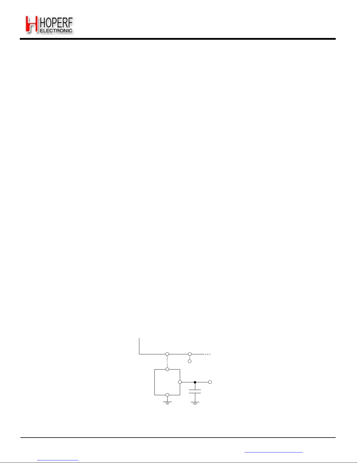
An external clock can be used to replace the crystal oscillator, for instance a tight tolerance TCXO. To do so, bit 4 at
address 0x59 should be set to 1, and the external clock has to be provided on XTA (pin 4). XTB (pin 5) should be left open.
The peak-peak amplitude of the input signal must never exceed 1.8 V. Please consult your TCXO supplier for an
appropriate value of decoupling capacitor, CD.
XTA
XTB
TCXO
32
MHz
NC
OP
Vcc
Vcc
GND
C
D
Figure 4. TCXO
Connection
Page 16

Page 16
RF65
Tel: +86-755-82973805 Fax: +86-755-82973550 E-mail: [email protected] http://www.hoperf.com
F =
XOS
C
ADVANCED COMMUNICATIONS & SENSING DATASHEET
3.3.2. CLKOUT Output
The reference frequency, or a fraction of it, can be provided on DIO5 (pin 13) by modifying bits ClkOut in RegDioMapping2.
Two typical applications of the CLKOUT output include:
To provide a clock output for a companion processor, thus saving the cost of an additional oscillator. CLKOUT can be
made available in any operation mode except Sleep mode and is automatically enabled at power on reset.
To provide an oscillator reference output. Measurement of the CLKOUT signal enables simple software trimming of the
initial crystal tolerance.
Note to minimize the current consumption of the RF65, please ensure that the CLKOUT signal is disabled when not
required.
3.3.3. PLL Architecture
The frequency synthesizer generating the LO frequency for the receiver is a fractional-N sigma-delta PLL. The PLL
incorporates a third order loop capable of fast auto-calibration, and it has a fast switching-time. The VCO and the loop filter
are both fully integrated, removing the need for an external tight-tolerance, high-Q inductor in the VCO tank circuit.
3.3.3.1. VCO
The VCO runs at 2, 4 or 6 times the RF frequency (respectively in the 915, 434 and 315 MHz bands) to reduce any LO
leakage in receiver mode, to improve the quadrature precision of the receiver.
The VCO calibration is fully automated. A coarse adjustment is carried out at power on reset, and a fine tuning is
performed each time the RF65 PLL is activated. Automatic calibration times are fully transparent to the end-user, as their
processing time is included in the TS_RE specifications.
3.3.3.2. PLL Bandwidth
The bandwidth of the RF65 Fractional-N PLL is wide enough to allow for very fast PLL lock times, enabling both short
startup and fast hop times required for frequency agile applications.
3.3.3.3. Carrier Frequency and Resolution
The RF65 PLL embeds a 19-bit sigma-delta modulator and its frequency resolution, constant over the whole frequency
range, and is given by:
F
STE
P
---------------2
19
The carrier frequency is programmed through RegFrf, split across addresses 0x07 to 0x09:
F
RF
= F
STEP
×
Frf(23,0)
Note The Frf setting is split across 3 bytes. A change in the center frequency will only be taken into account when the
least significant byte FrfLsb in RegFrfLsb is written.
Page 17
Page 17
RF65
Tel: +86-755-82973805 Fax: +86-755-82973550 E-mail: [email protected] http://www.hoperf.com
Decimator
Processing
ADVANCED COMMUNICATIONS & SENSING DATASHEET
3.3.4. Lock Time
PLL lock time TS_FS is a function of a number of technical factors, such as synthesized frequency, frequency step, etc.
When using the built-in sequencer, the RF65 optimizes the startup time and automatically starts the receiver when the
PLL has locked. To manually control the startup time, the user should either wait for TS_FS max given in the specification,
or monitor the signal PLL lock detect indicator, which is set when the PLL has is within its locking range.
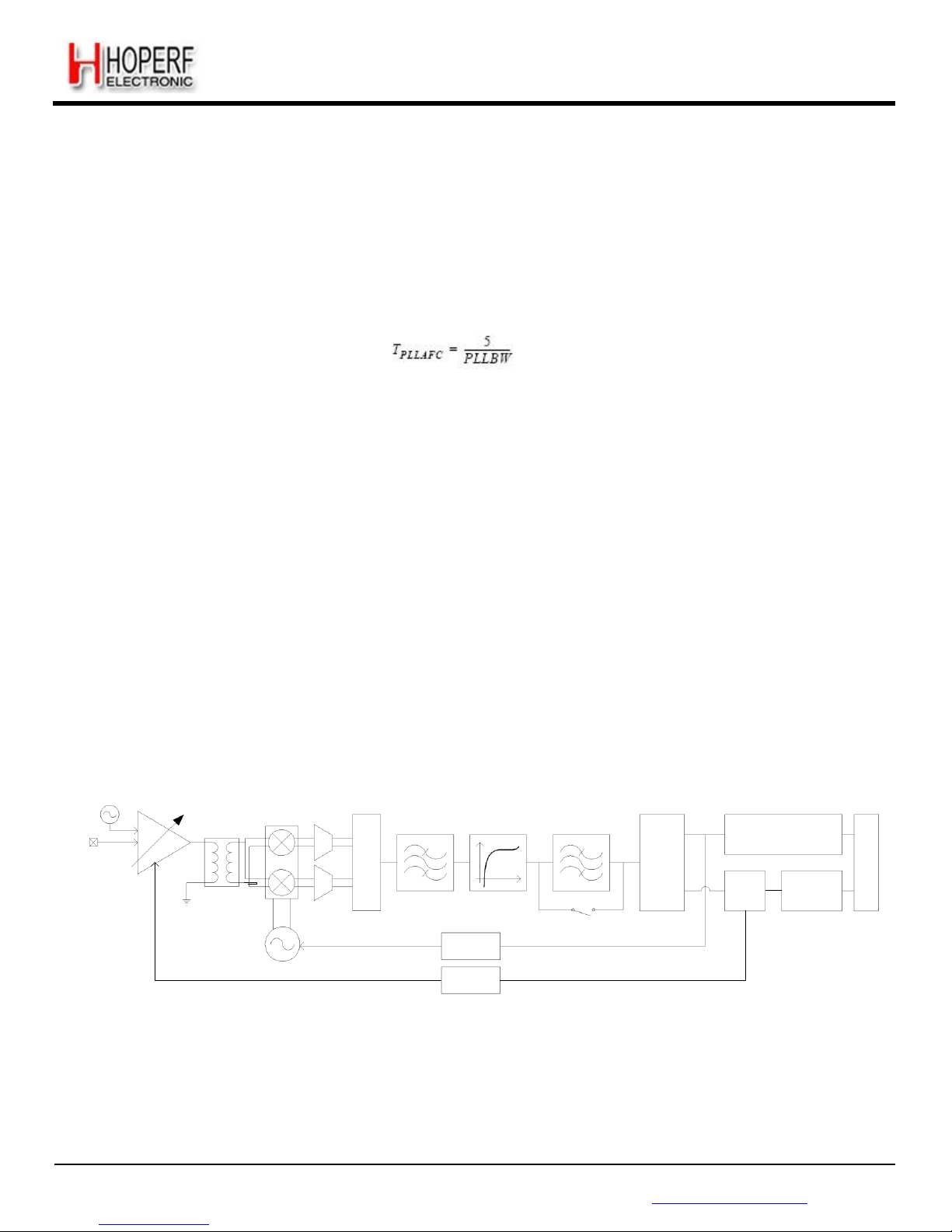
When performing an AFC, which usually corrects very small frequency errors, the PLL response time is approximately:
In a frequency hopping scheme, the timings TS_HOP given in the table of specifications give an order of magnitude for the
expected lock times.
3.3.5. Lock Detect Indicator
A lock indication signal can be made available on some of the DIO pins, and is toggled high when the PLL reaches its
locking range. Please refer to Table 17 and Table 18 to map this interrupt to the desired pins.
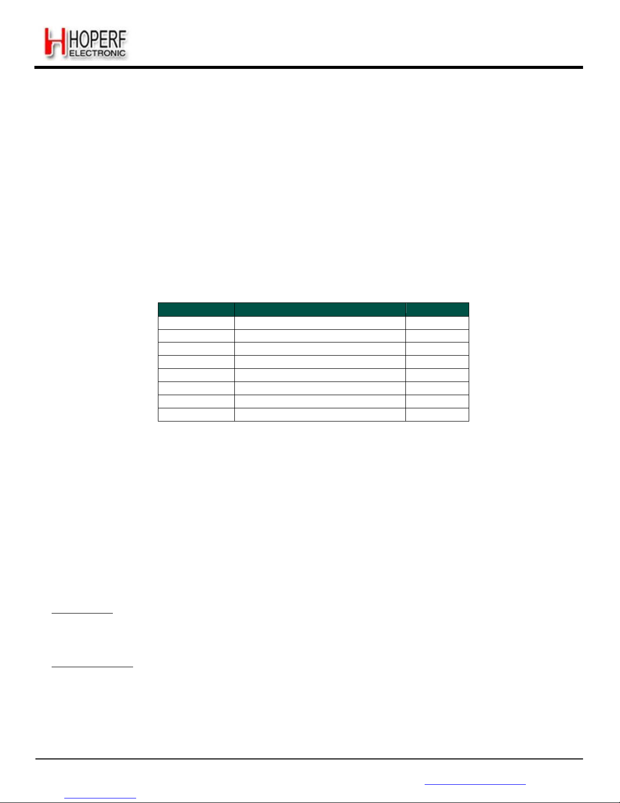
3.4. Receiver Description
The RF65 features a digital receiver with the analog to digital conversion process being performed directly following the
LNA-Mixers block. The zero-IF receiver is able to handle (G)FSK and (G)MSK modulation. ASK and OOK modulation is,
however, demodulated by a low-IF architecture. All the filtering, demodulation, gain control, synchronization and packet
handling is performed digitally, which allows a very wide range of bit rates and frequency deviations to be selected. The
receiver is also capable of automatic gain calibration in order to improve precision on RSSI measurements.
3.4.1. Block Diagram
Rx Calibration
Reference
RFIN
LNA
Single to
Differential
Mixers
Σ/
Δ
Modulators
Channel
Filter
DC
Cancellation
Complex
Filter
CORDIC
Phase
Output
Module
Output
RSSI
FSK
Demodulator
OOK
Demodulator
Local
Oscillator
AFC
Bypassed
in FSK
AGC
Figure 5. Receiver Block
Diagram
The following sections give a brief description of each of the receiver blocks.
Page 18
Page 18
RF65
Tel: +86-755-82973805 Fax: +86-755-82973550 E-mail: [email protected] http://www.hoperf.com
ADVANCED COMMUNICATIONS & SENSING DATASHEET
3.4.2. LNA - Single to Differential Buffer
The LNA uses a common-gate topology, which allows for a flat characteristic over the whole frequency range. It is
designed to have an input impedance of 50 Ohms or 200 Ohms (as selected with bit LnaZin in RegLna), and the parasitic
capacitance at the LNA input port is cancelled with the external RF choke. A single to differential buffer is implemented to
improve the second order linearity of the receiver.
The LNA gain, including the single-to-differential buffer, is programmable over a 48 dB dynamic range, and control is either
manual or automatic with the embedded AGC function.
Note In the specific case where the LNA gain is manually set by the user, the receiver will not be able to properly handle
FSK signals with a modulation index smaller than 2 at an input power greater than the 1dB compression point,
tabulated in section 3.4.3.
Table 8 LNA Gain Settings
LnaGainSelect
LNA Gain
Gain Setting
000
Any of the below, set by the AGC loop
-
001
Max gain
G1
010
Max gain - 6 dB
G2
011
Max gain - 12 dB
G3
100
Max gain - 24 dB
G4
101
Max gain - 36 dB
G5
110
Max gain - 48 dB
G6
111
Reserved
-
3.4.3. Automatic Gain Control
By default (LnaGainSelect = 000), the LNA gain is controlled by a digital AGC loop in order to obtain the optimal sensitivity/
linearity trade-off.
Regardless of the data transfer mode (Packet or Continuous), the following series of events takes place when the receiver
is enabled:
The receiver stays in WAIT mode, until RssiValue exceeds RssiThreshold for two consecutive samples. Its power
consumption is the receiver power consumption.
When this condition is satisfied, the receiver automatically selects the most suitable LNA gain, optimizing the sensitivity/
linearity trade-off.
The programmed LNA gain, read-accessible with LnaCurrentGain in RegLna, is carried on for the whole duration of the
packet, until one of the following conditions is fulfilled:
Packet mode: if AutoRxRestartOn = 0, the LNA gain will remain the same for the reception of the following packet. If
AutoRxRestartOn = 1, after the controller has emptied the FIFO the receiver will re-enter the WAIT mode described
above, after a delay of InterPacketRxDelay, allowing for the distant transmitter to ramp down, hence avoiding a false
RSSI detection. In both cases (AutoRxRestartOn=0 or AutoRxRestartOn=1), the receiver can also re-enter the WAIT
mode by setting RestartRx bit to 1. The user can decide to do so, to manually launch a new AGC procedure.
Continuous mode: upon reception of valid data, the user can decide to either leave the receiver enabled with the same
LNA gain, or to restart the procedure, by setting RestartRx bit to 1, resuming the WAIT mode of the receiver, described
above.
Notes - the AGC procedure must be performed while receiving preamble in FSK mode
- in OOK mode, the AGC will give better results if performed while receiving a constant “1”
sequence
Page 19
Page 19
RF65
Tel: +86-755-82973805 Fax: +86-755-82973550 E-mail: [email protected] http://www.hoperf.com
ADVANCED COMMUNICATIONS & SENSING DATASHEET
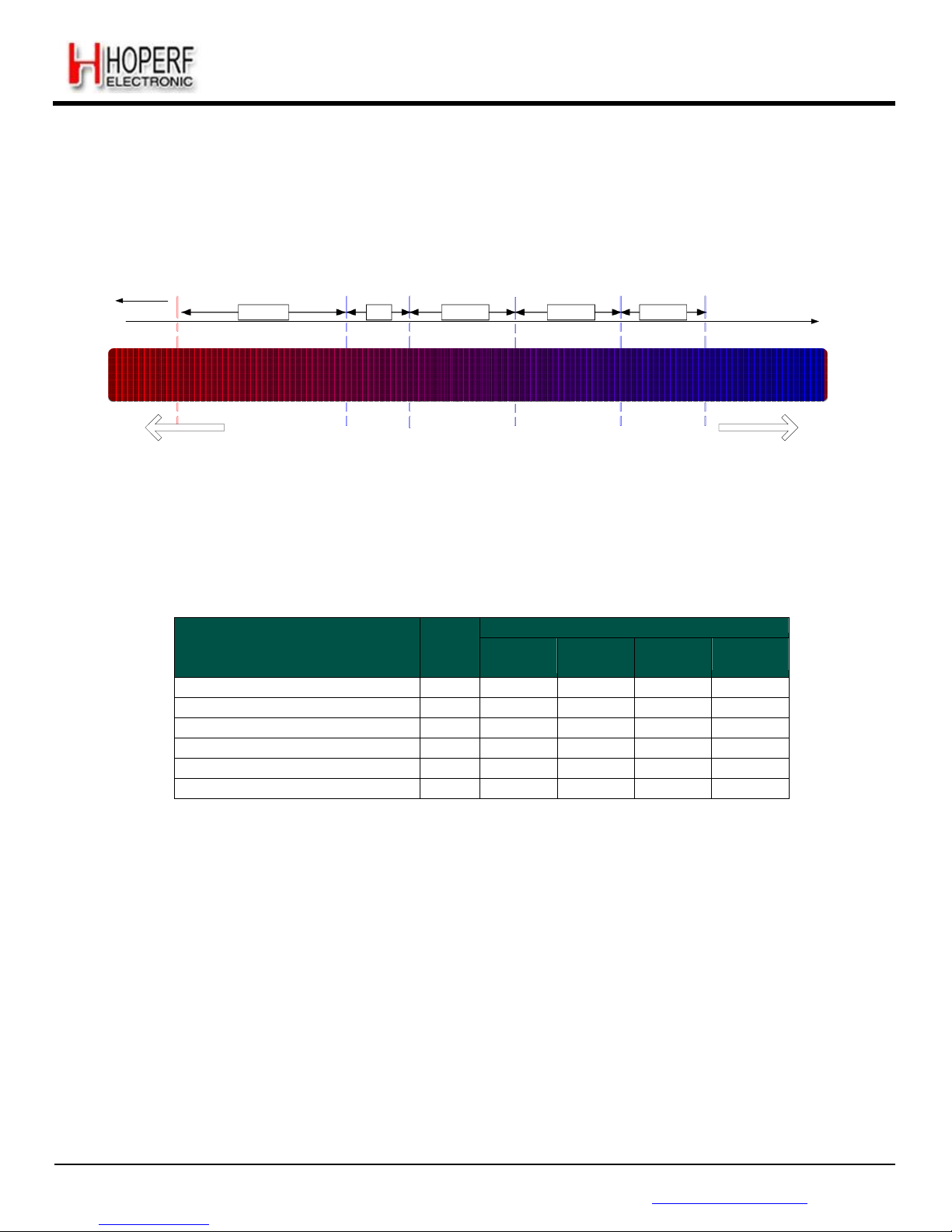
The following figure illustrates the AGC behavior::
Towards
-125
dBm
16dB 7dB 11dB 9dB 11dB
Pin
[dBm]
G1 G2 G3 G4 G5
G6
Higher
Sensitivity
Lower
Linearity
Lower Noise
Figure
Lower
Sensitivity
Higher
Linearity
Higher Noise
Figure
Figure 6. AGC Thresholds
Settings
The following table summarizes the performance (typical figures) of the complete receiver:
Table 9 Receiver Performance Summary
Input Power
Pin
Gain
Setting
Receiver Performance (typ)
P
-1dB
[dBm]
NF
[dB]
IIP3
[dBm]
IIP2
[dBm]
Pin < AgcThresh1
G1
-37 7 -18
+35
AgcThresh1 < Pin < AgcThresh2
G2
-31
13
-15
+40
AgcThresh2 < Pin < AgcThresh3
G3
-26
18
-8
+48
AgcThresh3 < Pin < AgcThresh4
G4
-14
27
-1
+62
AgcThresh4 < Pin < AgcThresh5
G5
>-6
36
+13
+68
AgcThresh5 < Pin
G6
>0
44
+20
+75
3.4.3.1. RssiThreshold Setting
For correct operation of the AGC, RssiThreshold in RegRssiThresh must be set to the sensitivity of the receiver. The
receiver will remain in WAIT mode until RssiThreshold is exceeded.
Note When AFC is enabled and performed automatically at the receiver startup, the channel filter used by the receiver
during the AFC and the AGC is RxBwAfc instead of the standard RxBw setting. This may impact the sensitivity of
the receiver, and the setting of RssiThreshold accordingly
3.4.3.2. AGC Reference
The AGC reference level is automatically computed in the RF65, according to:
AGC Reference [dBm] = -174 + NF + DemodSnr +10.log(2*RxBw) + FadingMargin [dBm]
Page 20

Page 20
RF65
Tel: +86-755-82973805 Fax: +86-755-82973550 E-mail: [email protected] http://www.hoperf.com
ADVANCED COMMUNICATIONS & SENSING DATASHEET
3.4.4. Continuous-Time DAGC
In addition to the automatic gain control described in section 3.4.3, the RF65 is capable of continuously adjusting its gain in
the digital domain, after the analog to digital conversion has occured. This feature, named DAGC, is fully transparent to the
end user. The digital gain adjustment is repeated every 2 bits, and has the following benefits:
Fully transparent to the end user
Improves the fading margin of the receiver during the reception of a packet, even if the gain of the LNA is frozen
Improves the receiver robustness in fast fading signal conditions, by quickly adjusting the receiver gain (every 2 bits)
Works in Continuous, Packet, and unlimited length Packet modes
The DAGC is enabled by setting RegTestDagc to 0x10 for low modulation index systems (i.e. when AfcLowBetaOn=1,
refer to section 3.4.17), and 0x30 for other systems. See section 9.5 for details. It is recommended to always enable the
DAGC.
3.4.5. Quadrature Mixer - ADCs - Decimators
The mixer is inserted between output of the RF buffer stage and the input of the analog to digital converter (ADC) of the
receiver section. This block is designed to translate the spectrum of the input RF signal to base-band, and offer both high
IIP2 and IIP3 responses.
In the lower bands of operation (290 to 510 MHz), the multi-phase mixing architecture with weighted phases improves the
rejection of the LO harmonics in receiver mode, hence increasing the receiver immunity to out-of-band interferers.
The I and Q digitalization is made by two 5
th
order continuous-time Sigma-Delta Analog to Digital Converters (ADC). Their
gain is not constant over temperature, but the whole receiver is calibrated before reception, so that this inaccuracy has no
impact on the RSSI precision. The ADC output is one bit per channel. It needs to be decimated and filtered afterwards. This
ADC can also be used for temperature measurement, please refer to section 3.4.18 for more details.
The decimators decrease the sample rate of the incoming signal in order to optimize the area and power consumption of
the following receiver blocks.
3.4.6. Channel Filter
The role of the channel filter is to filter out the noise and interferers outside of the channel. Channel filtering on the RF65 is
implemented with a 16-tap Finite Impulse Response (FIR) filter, providing an outstanding Adjacent Channel Rejection
performance, even for narrowband applications.
Note to respect oversampling rules in the decimation chain of the receiver, the Bit Rate cannot be set at a higher value
than 2 times the single-side receiver bandwidth (BitRate < 2 x RxBw)
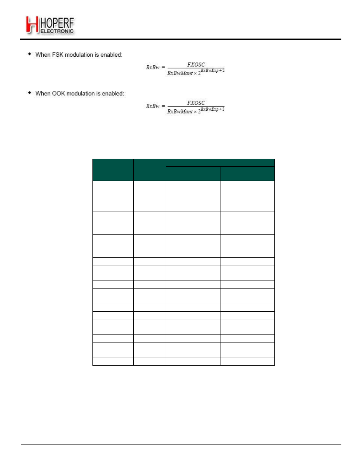
The single-side channel filter bandwidth RxBw is controlled by the parameters RxBwMant and RxBwExp in RegRxBw:
Page 21
Page 21
RF65
Tel: +86-755-82973805 Fax: +86-755-82973550 E-mail: [email protected] http://www.hoperf.com
ADVANCED COMMUNICATIONS & SENSING DATASHEET
The following channel filter bandwidths are accessible (oscillator is mandated at 32 MHz):
Table 10 Available RxBw Settings
RxBwMant
(binary/value)
RxBwExp
(decimal)
RxBw (kHz)
FSK
ModulationType=00
OOK
ModulationType=01
10b / 24 7 2.6
1.3
01b / 20 7 3.1
1.6
00b / 16 7 3.9
2.0
10b / 24 6 5.2
2.6
01b / 20 6 6.3
3.1
00b / 16 6 7.8
3.9
10b / 24 5 10.4
5.2
01b / 20 5 12.5
6.3
00b / 16 5 15.6
7.8
10b / 24 4 20.8
10.4
01b / 20 4 25.0
12.5
00b / 16 4 31.3
15.6
10b / 24 3 41.7
20.8
01b / 20 3 50.0
25.0
00b / 16 3 62.5
31.3
10b / 24 2 83.3
41.7
01b / 20 2 100.0
50.0
00b / 16 2 125.0
62.5
10b / 24 1 166.7
83.3
01b / 20 1 200.0
100.0
00b / 16 1 250.0
125.0
10b / 24 0 333.3
166.7
01b / 20 0 400.0
200.0
00b / 16 0 500.0
250.0
3.4.7. DC Cancellation
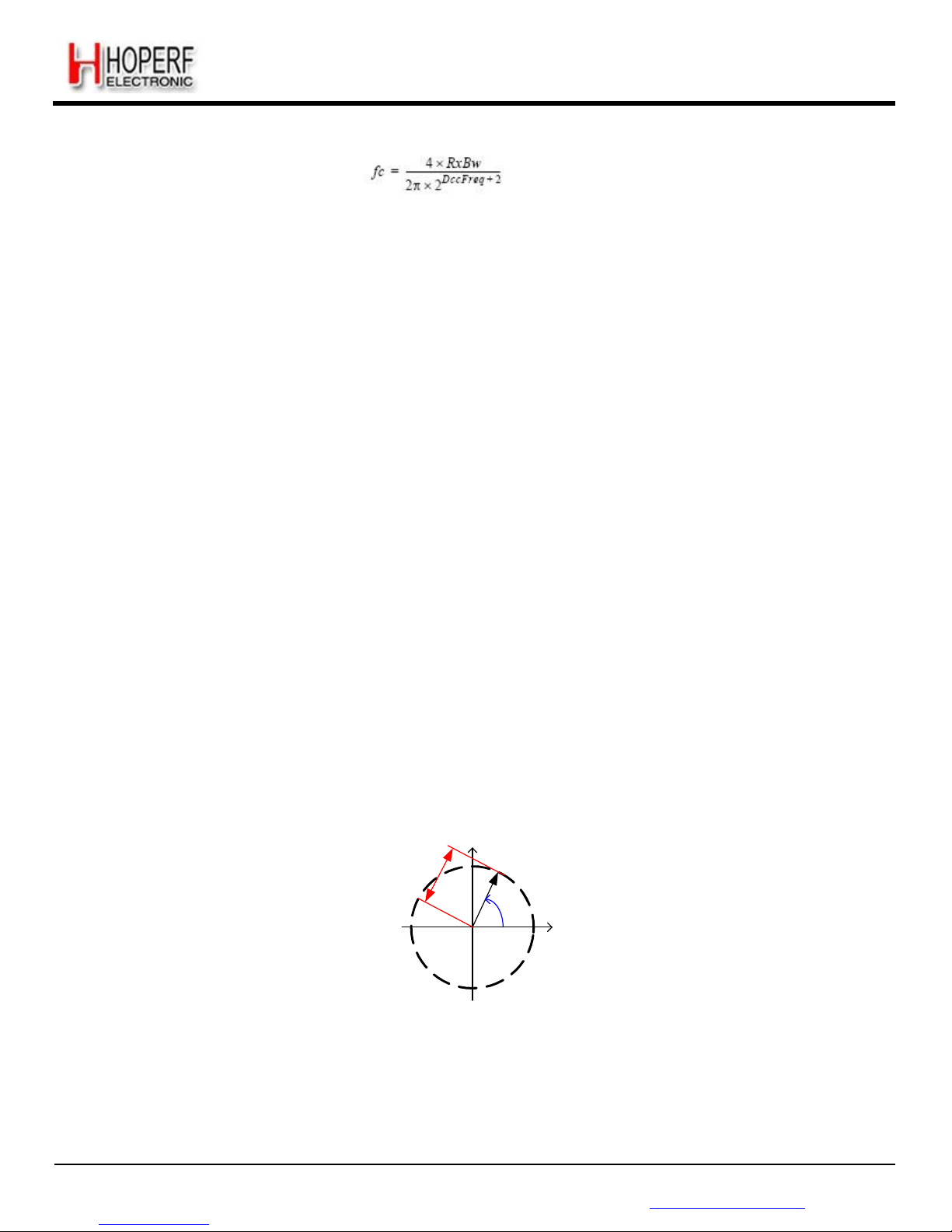
DC cancellation is required in zero-IF architecture receivers to remove any DC offset generated through self-reception. It is
built-in the RF65 and its adjustable cutoff frequency fc is controlled in RegRxBw:
Page 22
Page 22
RF65
Tel: +86-755-82973805 Fax: +86-755-82973550 E-mail: [email protected] http://www.hoperf.com
ADVANCED COMMUNICATIONS & SENSING DATASHEET
fc =
---
------
The default value of DccFreq cutoff frequency is typically 4% of the RxBw (channel filter BW). The cutoff frequency of the
DCC can however be increased to slightly improve the sensitivity, under wider modulation conditions. It is advised to adjust
the DCC setting while monitoring the receiver sensitivity.
3.4.8. Complex Filter - OOK
In OOK mode the RF65 is modified to a low-IF architecture. The IF frequency is automatically set to half the single side
bandwidth of the channel filter (F
IF
= 0.5 x RxBw). The Local Oscillator is automatically offset by the IF in the OOK receiver.
A complex filter is implemented on the chip to attenuate the resulting image frequency by typically 30 dB.
Note this filter is automatically bypassed when receiving FSK signals (ModulationType = 00 in RegDataModul).
3.4.9. RSSI
The RSSI block evaluates the amount of energy available within the receiver channel bandwidth. Its resolution is 0.5 dB,
and it has a wide dynamic range to accommodate both small and large signal levels that may be present. Its acquisition
time is very short, taking only 2 bit periods. The RSSI sampling must occur during the reception of preamble in FSK, and
constant “1” reception in OOK.
Note - The receiver is capable of automatic gain calibration, in order to improve the precision of its RSSI measurements.
This function injects a known RF signal at the LNA input, and calibrates the receiver gain accordingly. This
calibration is automatically performed during the PLL start-up, making it a transparent process to the end-user.
- RssiValue can only be read when it exceeds RssiThreshold
3.4.10. Cordic
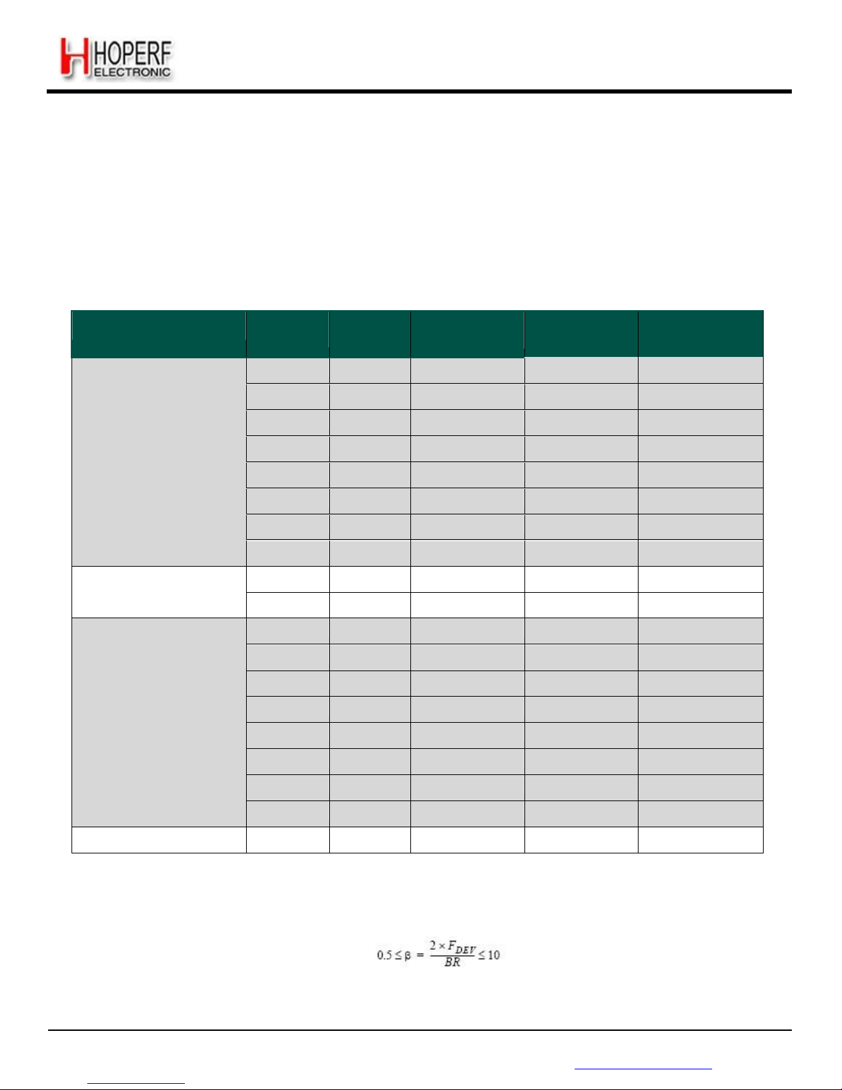
The Cordic task is to extract the phase and the amplitude of the modulation vector (I+j.Q). This information, still in the
digital domain is used:
Phase output: used by the FSK demodulator and the AFC blocks.
Amplitude output: used by the RSSI block, for FSK dem odulation, AGC and automatic gain calibration purposes.
Real-time
Magnitude
Q(t)
Real-time Phase
I(t)
Figure 7. Cordic
Extraction
3.4.11. Bit Rate Setting
Page 23
Page 23
RF65
Tel: +86-755-82973805 Fax: +86-755-82973550 E-mail: [email protected] http://www.hoperf.com
ADVANCED COMMUNICATIONS & SENSING DATASHEET
The Bit Rate (BR) is controlled by bits BitRate in RegBitrate:
F
XO S
C
BR =
-------------------
BitRate
Amongst others, the following Bit Rates are accessible:
Table 11 Bit Rate Examples
Type
BitRate
(15:8)
BitRate
(7:0)
(G)FSK
(G)MSK
OOK
Actual BR
(b/s)
Classical modem baud rates
(multiples of 1.2 kbps)
0x68
0x2B
1.2 kbps
1.2 kbps
1200.015
0x34
0x15
2.4 kbps
2.4 kbps
2400.060
0x1A
0x0B
4.8 kbps
4.8 kbps
4799.760
0x0D
0x05
9.6 kbps
9.6 kbps
9600.960
0x06
0x83
19.2 kbps
19.2 kbps
19196.16
0x03
0x41
38.4 kbps
38415.36
0x01
0xA1
76.8 kbps
76738.60
0x00
0xD0
153.6 kbps
153846.1
Classical modem baud rates
(multiples of 0.9 kbps)
0x02
0x2C
57.6 kbps
57553.95
0x01
0x16
115.2 kbps
115107.9
Round bit rates
(multiples of 12.5, 25 and
50 kbps)
0x0A
0x00
12.5 kbps
12.5 kbps
12500.00
0x05
0x00
25 kbps
25 kbps
25000.00
0x02
0x80
50 kbps
50000.00
0x01
0x40
100 kbps
100000.0
0x00
0xD5
150 kbps
150234.7
0x00
0xA0
200 kbps
200000.0
0x00
0x80
250 kbps
250000.0
0x00
0x6B
300 kbps
299065.4
Watch Xtal frequency
0x03
0xD1
32.768 kbps
32.768 kbps
32753.32
3.4.12. FSK Demodulator
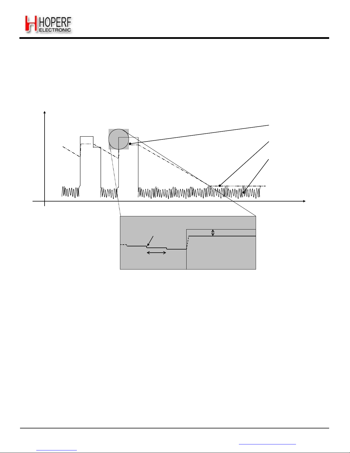
The FSK demodulator of the RF65 is designed to demodulate FSK, GFSK, MSK and GMSK modulated signals. It is
most efficient when the modulation index of the signal is greater than 0.5 and below 10:
0.5
≤
β
The output of the FSK demodulator can be fed to the Bit Synchronizer (described in section 3.4.14), to provide the
companion processor with a synchronous data stream in Continuous mode.
Page 24
Page 24
RF65
Tel: +86-755-82973805 Fax: +86-755-82973550 E-mail: [email protected] http://www.hoperf.com
ADVANCED COMMUNICATIONS & SENSING DATASHEET
3.4.13. OOK Demodulator
The OOK demodulator performs a comparison of the RSSI output and a threshold value. Three different threshold modes
are available, configured through bits OokThreshType in RegOokPeak.
The recommended mode of operation is the "Peak" threshold mode, illustrated in Figure 8:
RSSI
[dBm]
„‟Peak -6dB‟‟
Threshold
„‟Floor‟‟ threshold defined by
OokFixedThresh
Noise floor
of
receiver
Time
Zoom
Decay in dB as defined in
OokPeakThreshStep
Fixed 6dB
difference
Period as defined in
OokPeakThreshDec
Figure 8. OOK Peak Demodulator
Description
In peak threshold mode the comparison threshold level is the peak value of the RSSI, reduced by 6dB. In the absence of
an input sig nal, or during the reception of a logical "0", the acquired peak value is decremented by one
OokPeakThreshStep every OokPeakThreshDec period.
When the RSSI output is null for a long time (for instance after a long string of "0" received, or if no transmitter is present),
the peak threshold level will continue falling until it reaches the "Floor Threshold", programmed in OokFixedThresh.
The default settings of the OOK demodulator lead to the performance stated in the electrical specification. However, in
applications in which sudden signal drops are awaited during a reception, the three parameters should be optimized
accordingly.
3.4.13.1. Optimizing the Floor Threshold
OokFixedThresh determines the sensitivity of the OOK receiver, as it sets the comparison threshold for weak input signals
(i.e. those close to the noise floor). Significant sensitivity improvements can be generated if configured correctly.
Page 25
Page 25
RF65
Tel: +86-755-82973805 Fax: +86-755-82973550 E-mail: [email protected] http://www.hoperf.com
ADVANCED COMMUNICATIONS & SENSING DATASHEET
Note that the noise floor of the receiver at the demodulator input depends on:
The noise figure of the receiver.
The gain of the receive chain from antenna to base band.
The matching - including SAW filter if any.
The bandwidth of the channel filters.
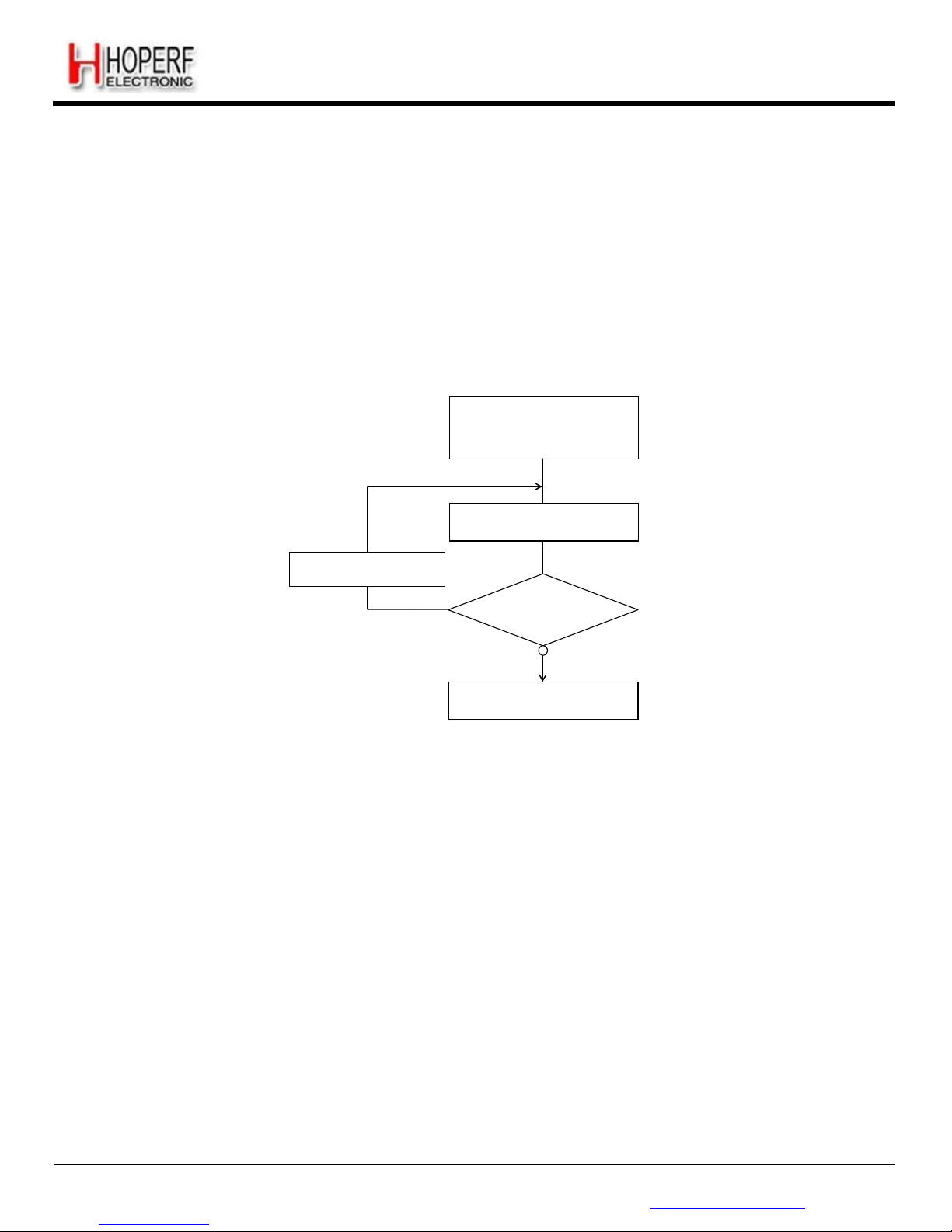
It is therefore important to note that the setting of OokFixedThresh will be application dependant. The following procedure
is recommended to optimize OokFixedThresh.
Set RF65 in OOK Rx
mode
Adjust
Bit Rate, Channel filter
BW
Default
OokFixedThresh setting
No input
signal
Continuous
Mode
Monitor DIO2/DATA
pin
Increment
OokFixedThresh
Glitch
activity
on DATA ?
Optimization
complete
Figure 9. Floor Threshold Optimization
The new floor threshold value found during this test should be used for OOK reception with those receiver settings.
3.4.13.2. Optimizing OOK Demodulator for Fast Fading Signals
A sudden drop in signal strength can cause the bit error rate to increase. For applications where the expected signal drop
can be estimated, the following OOK demodulator parameters OokPeakThreshStep and OokPeakThreshDec can be
optimized as described below for a given number of threshold decrements per bit. Refer to RegOokPeak to access those
settings.
3.4.13.3. Alternative OOK Demodulator Threshold Modes
In addition to the Peak OOK threshold mode, the user can alternatively select two other types of threshold detectors:
Fixed Threshold: The value is selected through OokFixedThresh
Average Threshold: Data supplied by the RSSI block is averaged, and this operation mode should only be used with
DC-free encoded data.
Page 26
Page 26
RF65
Tel: +86-755-82973805 Fax: +86-755-82973550 E-mail: [email protected] http://www.hoperf.com
ADVANCED COMMUNICATIONS & SENSING DATASHEET
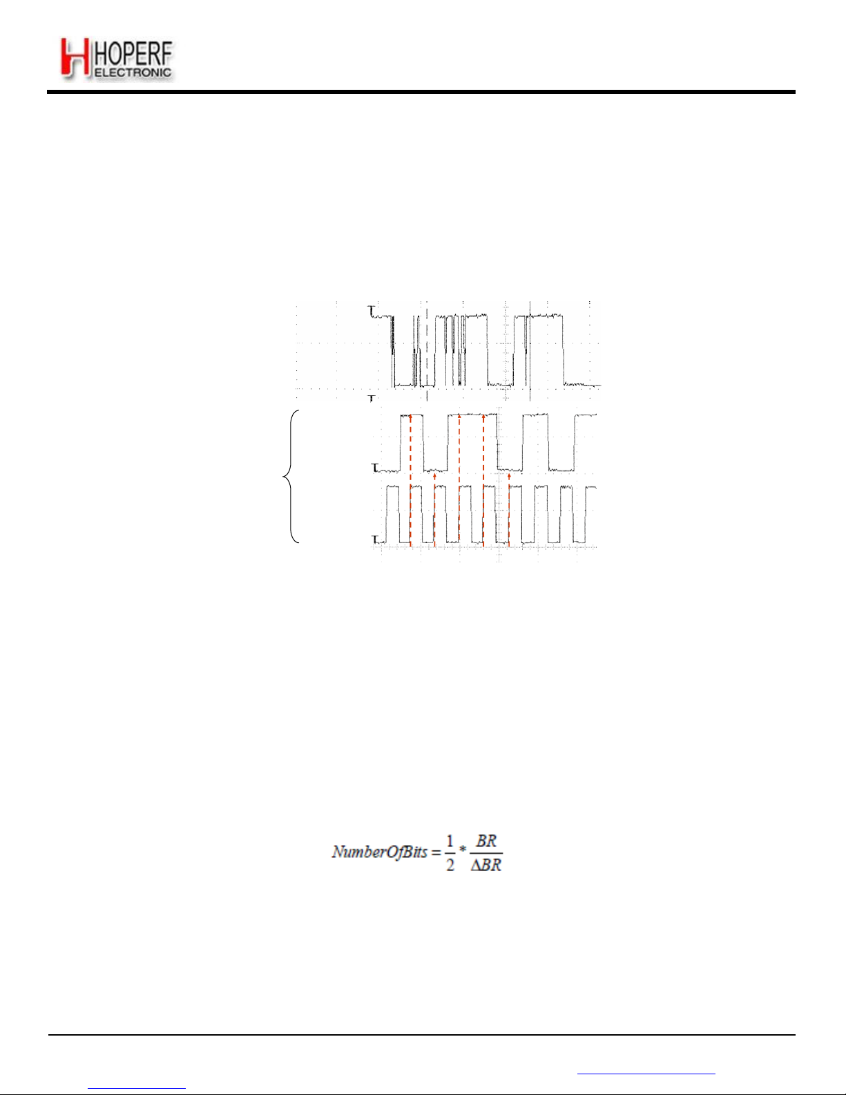
3.4.14. Bit Synchronizer
The Bit Synchronizer is a block that provides a clean and synchronized digital output, free of glitches. Its output is made
available on pin DIO1/DCLK in Continuous mode and can be disabled through register settings. However, for optimum
receiver performance its use when running Continuous mode is strongly advised.
The Bit Synchronizer is automatically activated in Packet mode. Its bit rate is controlled by BitRateMsb and BitRateLsb in
RegBitrate.
Raw demodulator
output
(FSK or OOK)
BitSync Output To
pin DATA and
DCLK in continuous
mode
DATA
DCLK
Figure 10. Bit Synchronizer
Description
To ensure correct operation of the Bit Synchronizer, the following conditions have to be satisfied:
A preamble (0x55 or 0xAA) of 12 bits is required for synchronization (from the RxReady interrupt)
The subsequent payload bit stream must have at least one transition form '0' to '1' or '1' to '0 every 16 bits during data
transmission
The bit rate matching between the transmitter and the receiver must be better than 6.5 %.
Notes - If the Bit Rates of Transmitter and Receiver are known to be the same, the RF65 will be able to receive an
infinite unbalanced sequence (all “0s” or all ”1s”) with no restriction.
- If there is a difference in Bit Rate between Tx and Rx, the amount of adjacent bits at the same level that the
BitSync can withstand can be estimated as follows:
- This implies approximately 6 consecutive unbalanced bytes when the Bit Rate precision is 1%, which is easily
achievable (crystal tolerance is in the range of 50 to 100 ppm).
3.4.15. Frequency Error Indicator
This function provides information about the frequency error of the local oscillator (LO) compared with the carrier frequency
of a modulated signal at the input of the receiver. When the FEI block is launched, the frequency error is measured and the
Page 27
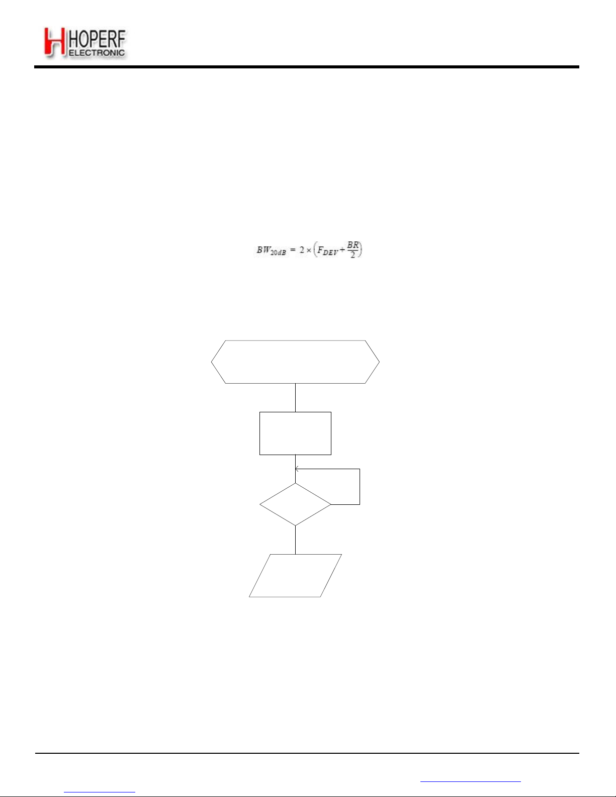
Page 27
RF65
Tel: +86-755-82973805 Fax: +86-755-82973550 E-mail: [email protected] http://www.hoperf.com
ADVANCED COMMUNICATIONS & SENSING DATASHEET
signed result is loaded in FeiValue in RegFei, in 2‟s complement format. The time required for an FEI evaluation is 4 times
the bit period.
To ensure a proper behavior of the FEI:
The operation must be done during the reception of preamble
The sum of the frequency offset and the 20 dB signal bandwidth must be lower than the base band filter bandwidth
The 20 dB bandwidth of the signal can be evaluated as follows (double-side bandwidth):
The frequency error, in Hz, can be calculated with the following formula:
FEI = F
STEP
×
Fe
iValue
RF65 in Rx
mode
Preamble-
modulated input
signal
Signal
level >
Sensitivity
Set
FeiStar
t
=
1
FeiDone
No
=
1
Yes
Read
FeiValue
Figure 11. FEI
Process
3.4.16. Automatic Frequency Correction
The AFC is based on the FEI block, and therefore the same input signal and receiver setting conditions apply. When the
AFC procedure is done, AfcValue is directly subtracted to the register that defines the frequency of operation of the chip,
FRF. The AFC can be launched:
Each time the receiver is enabled, if AfcAutoOn = 1
Upon user request, by setting bit AfcStart in RegAfcFei, if AfcAutoOn = 0
Page 28
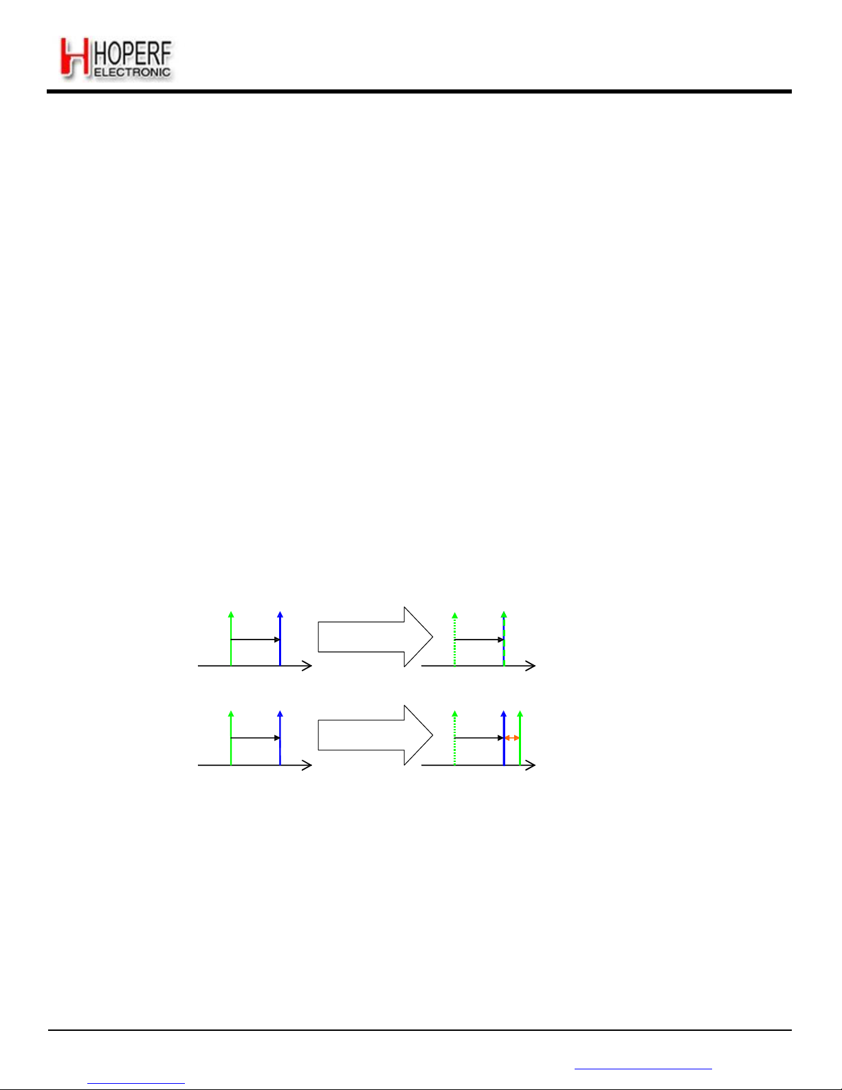
Page 28
RF65
Tel: +86-755-82973805 Fax: +86-755-82973550 E-mail: [email protected] http://www.hoperf.com
ADVANCED COMMUNICATIONS & SENSING DATASHEET
When the AFC is automatically triggered (AfcAutoOn = 1), the user has the option to:
Clear the former AFC correction value, if AfcAutoClearOn = 1
Start the AFC evaluation from the previously corrected frequency. This may be useful in systems in which the LO keeps
on drifting in the “same direction”. Ageing compensation is a good example.
The RF65 offers an alternate receiver bandwidth setting during the AFC phase, to accommodate large LO drifts. If the
user considers that the received signal may be out of the receiver bandwidth, a higher channel filter bandwidth can be
programmed in RegAfcBw, at the expense of the receiver noise floor, which will impact upon sensitivity.
3.4.17. Optimized Setup for Low Modulation Index Systems
For wide band systems, where AFC is usually not required (XTAL inaccuracies do not typically impact the sensitivity), it
is recommended to offset the LO frequency of the receiver to avoid desensitization. This can be simply done by
modifying Frf in RegFrfLsb. A good rule of thumb is to offset the receiver‟s LO by 10% of the expected transmitter
frequency deviation.
For narrow band systems, it is recommended to perform AFC. The RF65 has a dedicated AFC, enabled when
AfcLowBetaOn in RegAfcCtrl is set to 1. A frequency offset, programmable through LowBetaAfcOffset in RegTestAfc, is
added and is calculated as follows:
Offset = LowBetaAfcOffset x 488 Hz
The user should ensure that the programmed offset exceeds the DC canceller‟s cutoff frequency, set through DccFreqAfc
in RegAfcBw.
RX
TX
RX & TX
FeiValue
Standard AFC
AfcLowBetaOn = 0
AfcValue
f
f
RX
TX
TX RX
FeiValue
Optimized AFC
AfcLowBetaOn =
1
AfcValue LowBetaAfcOffset
f
f
Before AFC After
AFC
Figure 12. Optimized Afc
(AfcLowBetaOn=1)
As shown on Figure 12, a standard AFC sequence uses the result of the FEI to correct the LO frequency and align both
local oscillators. When the optimized AFC is enabled (AfcLowBetaOn=1), the receiver‟s LO is corrected by “FeiValue +
LowBetaAfcOffset”.
When the optimized AFC routine is enabled, the receiver startup time can be computed as follows (refer to section 4.2.1):
TS_RE_AGC&AFC (optimized AFC) = Tana + 4.Tcf + 4.Tdcc + 3.Trssi + 2.Tafc +
2.Tpllafc
Page 29

Page 29
RF65
Tel: +86-755-82973805 Fax: +86-755-82973550 E-mail: [email protected] http://www.hoperf.com
ADVANCED COMMUNICATIONS & SENSING DATASHEET
3.4.18. Temperature Sensor
When temperature is measured, the receiver ADC is used to digitize the sensor response. Most receiver blocks are
disabled, and temperature measurement can only be triggered in Standby or Frequency Synthesizer modes.
The response of the temperature sensor is -1°C / Lsb. A CMOS temperature sensor is not accurate by nature, therefore it
should be calibrated at ambient temperature for precise temperature readings.
TempValue
-1°C/Lsb
TempValue(t)
TempValue(t)-1
Returns 150d (typ.)
Needs calibration
-40°C
t t+1 Ambient
+85°C
Figure 13. Temperature Sensor
Response
It takes less than 100 microseconds for the RF65 to evaluate the temperature (from setting TempMeasStart to 1 to
TempMeasRunning reset).
3.4.19. Timeout Function
The RF65 includes a Timeout function, which allows it to automatically shut-down the receiver after a receive sequence
and therefore save energy.
Timeout interrupt is generated TimeoutRxStart x 8 x Tbit after switching to RX mode if RssiThreshold flag does not raise
within this time
frame
Timeout interrupt is generated TimeoutRssiThresh x 8 x Tbit after RssiThreshold flag has been raised.
This timeout interrupt can be used to warn the companion processor to shut down the receiver and return to a lower power
mode.
Page 30
Page 30
RF65
Tel: +86-755-82973805 Fax: +86-755-82973550 E-mail: [email protected] http://www.hoperf.com
ADVANCED COMMUNICATIONS & SENSING DATASHEET
4. Operating Modes
4.1. Basic Modes
The circuit can be set in 4 different basic modes which are described in Table 12.
By default, when switching from a mode to another one, the sub-blocks are woken up according to a pre-defined and
optimized sequence. Alternatively, these operating modes can be selected directly by disabling the automatic sequencer
(SequencerOff in RegOpMode = 1).
Table 12 Basic Receiver Modes
ListenOn
in RegOpMode
Mode
in RegOpMode
Selected mode
Enabled blocks
0
0 0 0
Sleep Mode
None
0
0 0 1
Stand-by Mode
Top regulator and crystal oscillator
0
0 1 0
FS Mode
Frequency synthesizer
0
1 0 0
Receive Mode
Frequency synthesizer and receiver
1
x
Listen Mode
See Listen Mode, section 4.3
4.2. Automatic Sequencer and Wake-Up Times
By default, when switching from one operating mode to another, the circuit takes care of the sequence of events in such a
way that the transition timing is optimized. For example, when switching from Sleep mode to Receive mode, the RF65
goes first to Standby mode (XO started), then to frequency synthesizer mode, and finally, when the PLL has locked, to
Receive mode.
The crystal oscillator wake-up time, TS_OSC, is directly related to the time for the crystal oscillator to reach its steady
state. It depends notably on the crystal characteristics.
The frequency synthesizer wake-up time, TS_FS, is directly related to the time needed by the PLL to reach its steady
state. The signal PLL_LOCK, provided on an external pin, gives an indication of the lock status. It goes high when the
PLL reaches its locking range.
Three specific cases can be highlighted:
Receiver Wake Up time from Sleep mode = TS_OSC + TS_FS + TS_RE
Receiver Wake Up time from Sleep mode, AGC enabled = TS_OSC + TS_FS + TS_RE_AGC
Receiver Wake Up time from Sleep mode, AGC and AFC enabled = TS_OSC + TS_FS + TS_RE_AGC&AFC
These timings are detailed in section 4.2.1.
In applications where the target average power consumption, or the target startup time, do not require setting the RF65 in
the lowest power modes (Sleep or Standby), the respective timings TS_OSC and TS_FS in the former equations can be
omitted.
4.2.1. Receiver Startup Time
It is highly recommended to use the built-in sequencer of the RF65, to optimize the delays when setting the chip in
receive mode. It guarantees the shortest startup times, hence the lowest possible energy usage, for battery operated
systems.
The startup times of the receiver can be calculated from the following:
Page 31
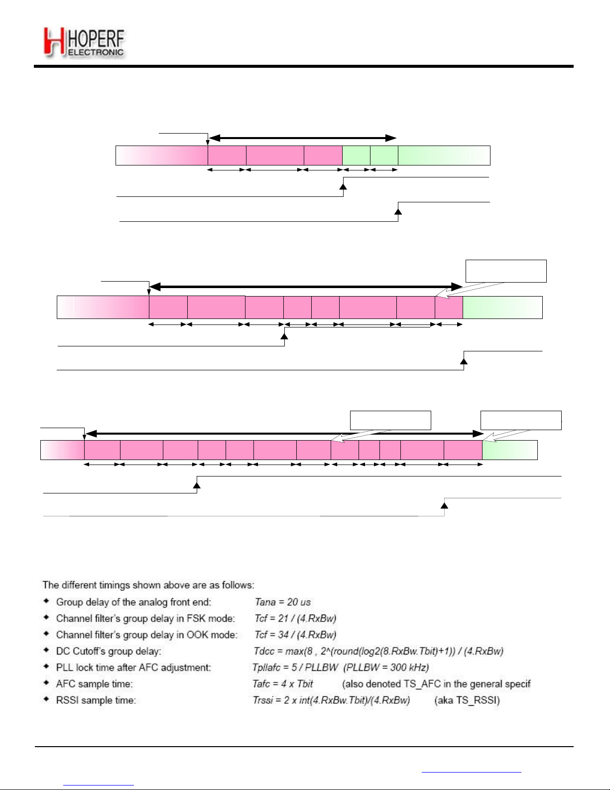
Page 31
RF65
Tel: +86-755-82973805 Fax: +86-755-82973550 E-mail: [email protected] http://www.hoperf.com
ADVANCED COMMUNICATIONS & SENSING DATASHEET
Rx startup
request
(sequencer or
user)
TS_RE
XO Started and PLL is locked
Analog FE‟s
group delay
Channel Filter‟s
group delay
DC Cutoff‟s
group delay
RSSI
sampling
RSSI
sampling
Reception of Packet
Tana
Tcf Tdcc Trssi Trssi
ModeReady
RxReady
Figure 14. Rx Startup - No AGC, no AFC
Rx startup request
(sequencer or user)
TS_RE_AGC
The LNA gain is adjusted
by
the AGC, according to
the
RSSI
result
XO Started and PLL is locked
Analog FE‟s
group delay
Channel Filter‟s
group delay
DC Cutoff‟s
group delay
RSSI
sampling
RSSI
sampling
Channel Filter‟s
group delay
DC Cutoff‟s
group delay
RSSI
sampling
Reception of Packet
Tana
Tcf Tdcc Trssi Trssi Tcf Tdcc Trssi
ModeReady
RxReady
Figure 15. Rx Startup - AGC, no AFC
Rx startup request
(sequencer or user)
TS_RE_AGC&AFC
The LNA gain is adjusted
by
the AGC, according to
the
RSSI
result
Carrier Frequency is adjusted
by the AFC
XO Started and
PLL is locked
Analog FE‟s
group delay
Channel Filter‟s
group delay
DC Cutoff‟s
group delay
RSSI
sampling
RSSI
sampling
Channel Filter‟s
group delay
DC Cutoff‟s
group delay
RSSI
sampling
AFC
PLL
lock
Channel Filter‟s
group delay
DC Cutoff‟s
group delay
Reception of Packet
Tana
Tcf Tdcc Trssi Trssi Tcf Tdcc Trssi Tafc Tpllafc Tcf Tdcc
ModeReady
RxReady
Figure 16. Rx Startup - AGC and
AFC
The different timings shown above are as follows:
Note The above timings represent maximum settling times, and shorter settling times may be observed in real cases
Page 32

Page 32
RF65
Tel: +86-755-82973805 Fax: +86-755-82973550 E-mail: [email protected] http://www.hoperf.com
ADVANCED COMMUNICATIONS & SENSING DATASHEET
4.2.2. Rx Start Procedure
As described in the former sections, the RxReady interrupt warns the uC that the receiver is ready.
In Continuous mode with Bit Synchronizer, the receiver will start locking its Bit Synchronizer on a minimum or 12 bits of
received preamble (see section 3.4.14 for details), before the reception of correct Data, or Sync Word (if enabled) can
occur.
In Continuous mode without Bit Synchronizer, valid data will be available on DIO2/DATA right after the RxReady
interrupt.
In Packet mode, the receiver will start locking its Bit Synchronizer on a minimum or 12 bits of received preamble (see
section 3.4.14 for details), before the reception of correct Data, or Sync Word (if enabled) can occur.
4.2.3. Optimized Frequency Hopping Sequences
In a frequency hopping-like application, it is required to turn off the receiver when hopping from one channel to another, to
optimize the hopping sequence:
Receiver hop from Ch A to Ch B:
(0) RF65 is in Rx mode in Ch A
(1) Change the carrier frequency in the RegFrf registers
(2) Program the RF65 in FS mode
(3) Turn the receiver back to Rx mode
(4) Respect the Rx start procedure, described in section 4.2.4
Note the above sequence assumes that the sequencer is turned on (SequencerOff=0 in RegOpMode).
Page 33
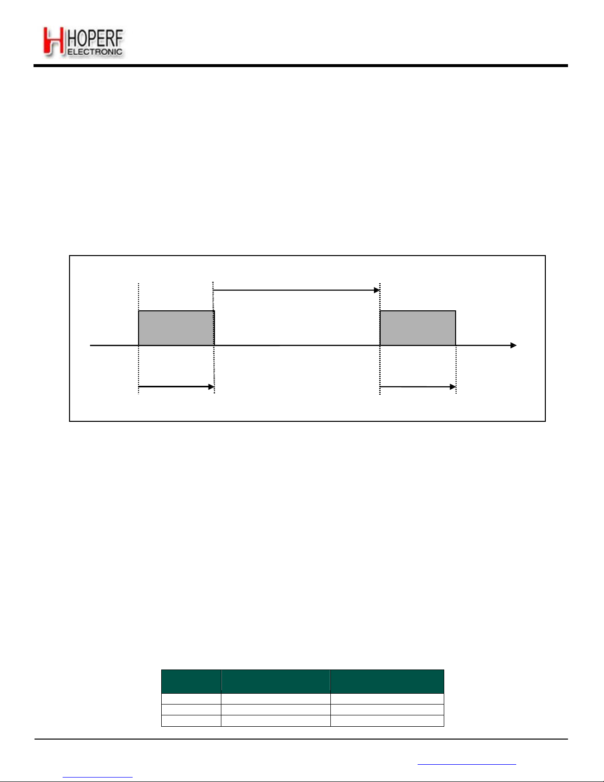
Page 33
RF65
Tel: +86-755-82973805 Fax: +86-755-82973550 E-mail: [email protected] http://www.hoperf.com
ADVANCED COMMUNICATIONS & SENSING DATASHEET
4.3. Listen Mode
The circuit can be set to Listen mode, by setting ListenOn in RegOpMode to 1 while in Standby mode. In this mode,
RF65 spends most of the time in Idle mode, during which only the RC oscillator runs. Periodically the receiver is woken up
and listens for an RF signal. If a wanted signal is detected, the receiver is kept on and the data is demodulated.
Otherwise, if a wanted signal hasn't been detected after a pre-defined period of time, the receiver is disabled until the next
time period.
This periodical Rx wake-up requirement is very common in low power applications. On RF65 it is handled locally by the
Listen mode block without using uC resources or energy.
The simplified timing diagram of this procedure is illustrated in Figure 17.
t
ListenIdle
Rx
Idle
Rx
time
t
ListenRx
t
ListenRx
Figure 17. Listen Mode Sequence (no wanted signal is received)
4.3.1. Timings
The duration of the Idle phase is given by t
ListenIdle
. The time during which the receiver is on and waits for a signal is given
by t
ListenRx
. t
ListenRx
includes the wake-up time of the receiver, described in section 4.2.1. This duration can be
programmed in the configuration registers via the serial interface.
Both time periods t
ListenRx
and t
ListenIdle
(denoted t
ListenX
in the following text) are fixed by two parameters from the
configuration register and are calculated as follows:
t
ListenX
=
ListenCoefX
⋅ Listen Re
solX
where ListenResolX is the Rx or Idle resolution and is independantly programmable on three values (64us, 4.1ms or
262ms), whereas ListenCoefX is an integer between 1 and 255. All parameters are located in RegListen registers.
The timing ranges are tabulated in Table 13 below.
Table 13 Range of Durations in Listen Mode
ListenResolX
Min duration
( ListenCoef = 1 )
Max duration
( ListenCoef = 255 )
01 64
us
16
ms
10 4.1
ms
1.04
s
11 0.26
s
67
s
Page 34
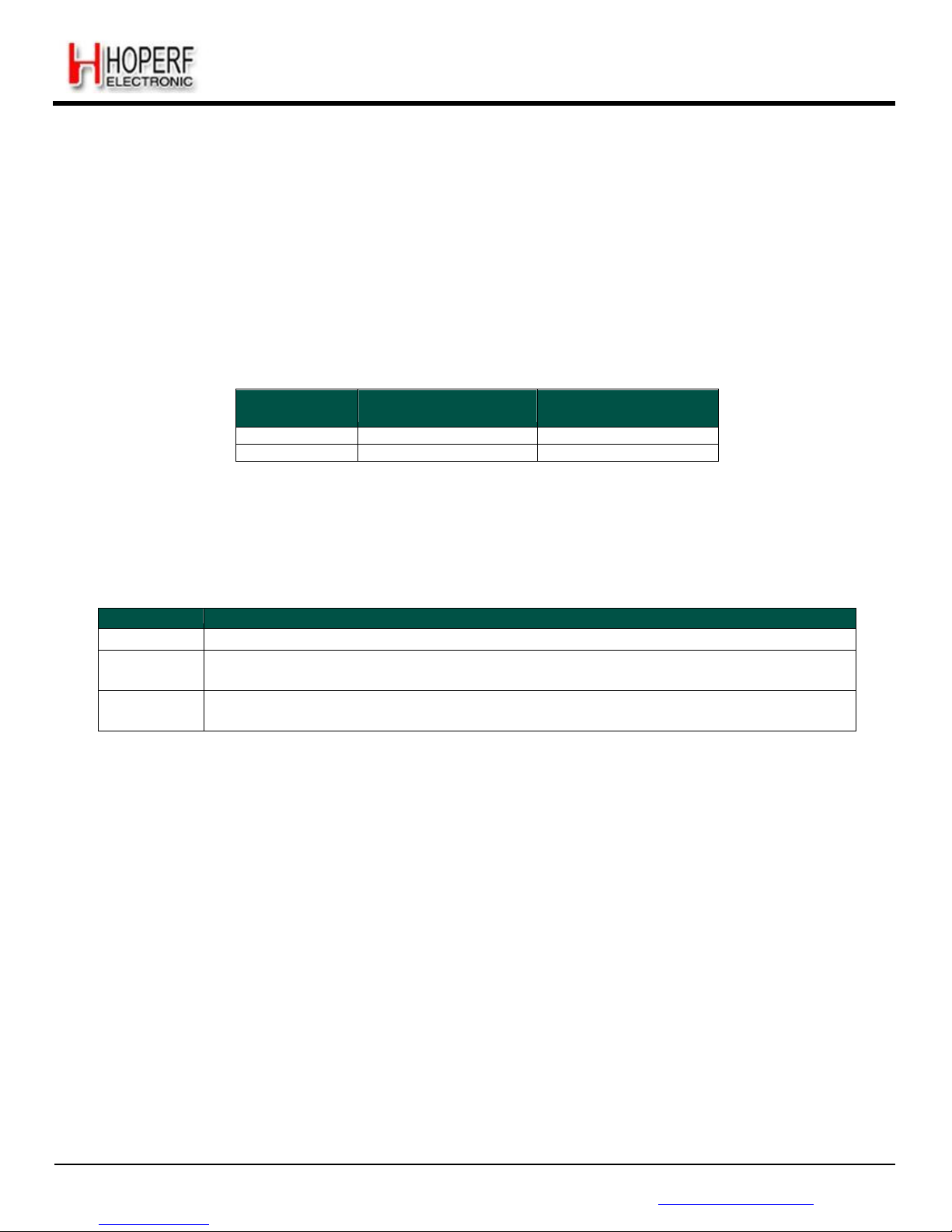
Page 34
RF65
Tel: +86-755-82973805 Fax: +86-755-82973550 E-mail: [email protected] http://www.hoperf.com
ADVANCED COMMUNICATIONS & SENSING DATASHEET
Notes - the accuracy of the typical timings given in Table 13 will depend in the RC oscillator calibration
- RC oscillator calibration is required, and must be performed at power up. See section 4.3.4 for details
4.3.2. Criteria
The criteria taken for detecting a wanted signal and hence deciding to maintain the receiver on is defined by ListenCriteria
in RegListen1.
Table 14 Signal Acceptance Criteria in Listen Mode
ListenCriteria
Input Signal Power
>= RssiThreshold
SyncAddressMatch
0 Required
Not Required
1 Required
Required
4.3.3. End of Cycle Actions
The action taken after detection of a packet, is defined by ListenEnd in RegListen3, as described in the table below.
Table 15 End of Listen Cycle Actions
ListenEnd
Description
00
Chip stays in Rx mode. Listen mode stops and must be disabled.
01
Chip stays in Rx mode until PayloadReady or Timeout interrupt occurs. It then goes to the
mode defined by Mode. Listen mode stops and must be disabled.
10
Chip stays in Rx mode until PayloadReady or Timeout interrupt occurs. Listen mode then
resumes in Idle state. FIFO content is lost at next Rx wakeup.
Page 35
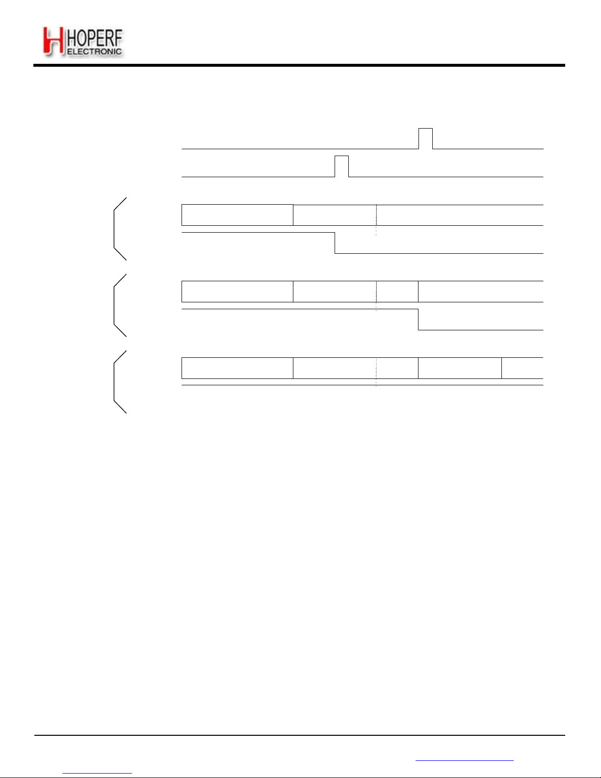
Page 35
RF65
Tel: +86-755-82973805 Fax: +86-755-82973550 E-mail: [email protected] http://www.hoperf.com
Idle
Rx
Idle
Rx
ADVANCED COMMUNICATIONS & SENSING DATASHEET
Upon detection of a valid packet, the sequencing is altered, as shown below:
PayloadReady
ListenCriteria
passed
ListenEnd = 00
Listen Mode
Idle Rx
ListenEnd = 01
ListenEnd = 10
Listen Mode
Listen Mode
Idle Rx
Mode
Figure 18. Listen Mode Sequence (wanted signal is received)
Listen mode can be disabled by writing ListenOn to 0
4.3.4. RC Timer Accuracy
All timings of the Listen Mode rely on the accuracy of the internal low-power RC oscillator. This oscillator is automatically
calibrated at the device power-up, and it is a user-transparent process.
For applications enduring large temperature variations, and for which the power supply is never removed, RC calibration
can be performed upon user request. RcCalStart in RegOsc1 can be used to trigger this calibration, and the flag
RcCalDone will be set automatically when the calibration is over.
Page 36
Page 36
RF65
Tel: +86-755-82973805 Fax: +86-755-82973550 E-mail: [email protected] http://www.hoperf.com
ADVANCED COMMUNICATIONS & SENSING DATASHEET
4.4. AutoModes
Automatic modes of packet handler can be enabled by configuring the related parameters in RegAutoModes.
The intermediate mode of the chip is called IntermediateMode and the enter and exit conditions to/from this interm ediate
mode can be configured through the parameters EnterCondition & ExitCondition.
The enter and exit conditions cannot be used independently of each other i.e. both should be enabled at the same time.
The initial and the final state is the one configured in the Mode in RegOpMode. The initial & final states can be different by
configuring the modes register while the chip is in intermediate mode. The pictorial description of the auto modes is shown
below.
Intermediate State
defined by IntermediateMode
EnterCondition
ExitCondition
Initial state defined
By Mode in RegOpMode
Final state defined
By Mode in RegOpMode
Figure 19. Auto Modes of Packet
Handler
Some typical examples of AutoModes usage are described below :
Automatic reception (AutoRx) : Mode = Rx, IntermediateMode = Sleep, EnterCondition = CrcOk, ExitCondition = falling
edge of FifoNotEmpty
...
Page 37
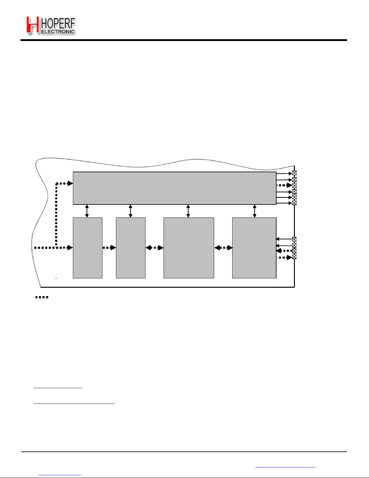
Page 37
RF65
Tel: +86-755-82973805 Fax: +86-755-82973550 E-mail: [email protected] http://www.hoperf.com
ADVANCED COMMUNICATIONS & SENSING DATASHEET
5. Data Processing
5.1. Overview
5.1.1. Block Diagram
Figure below illustrates the RF65 data processing circuit. Its role is to interface the data from the demodulator and the uC
access points (SPI and DIO pins). It also controls all the configuration registers.
The circuit contains several control blocks which are described in the following paragraphs.
Rx
CONTROL
DIO0
DIO1
DIO2
DIO3
DIO4
DIO5
Data
Rx
SYNC
RECOG.
PACKET
HANDLER
FIFO
(+SR)
SPI
NSS
SCK
MOSI
MISO
Potential dat apaths (data operation mode dependant)
Figure 20. RF65 Data Processing Conceptual
View
The RF65 implements several data operation modes, each with their own data path through the data processing section.
Depending on the data operation mode selected, some control blocks are active whilst others remain disabled.
5.1.2. Data Operation Modes
The RF65 has two different data operation modes selectable by the user:
Continuous mode: each bit received is accessed in real time at the DIO2/DATA pin. This mode may be used if adequate
external signal processing is available.
Packet mode (recommended): user only retrieves payload bytes from the FIFO. The packet engine automatically
removes the preamble, checks the Sync word, performs AES decryption, checks the CRC, and decodes DC-free
schemes if enabled. The uC processing overhead is hence significantly reduced compared to Continuous mode.
Depending on the optional features activated (CRC, AES, etc) the maximum payload length is limited to FIFO size, 255
bytes or unlimited.
Each of these data operation modes is described fully in the following sections.
Page 38
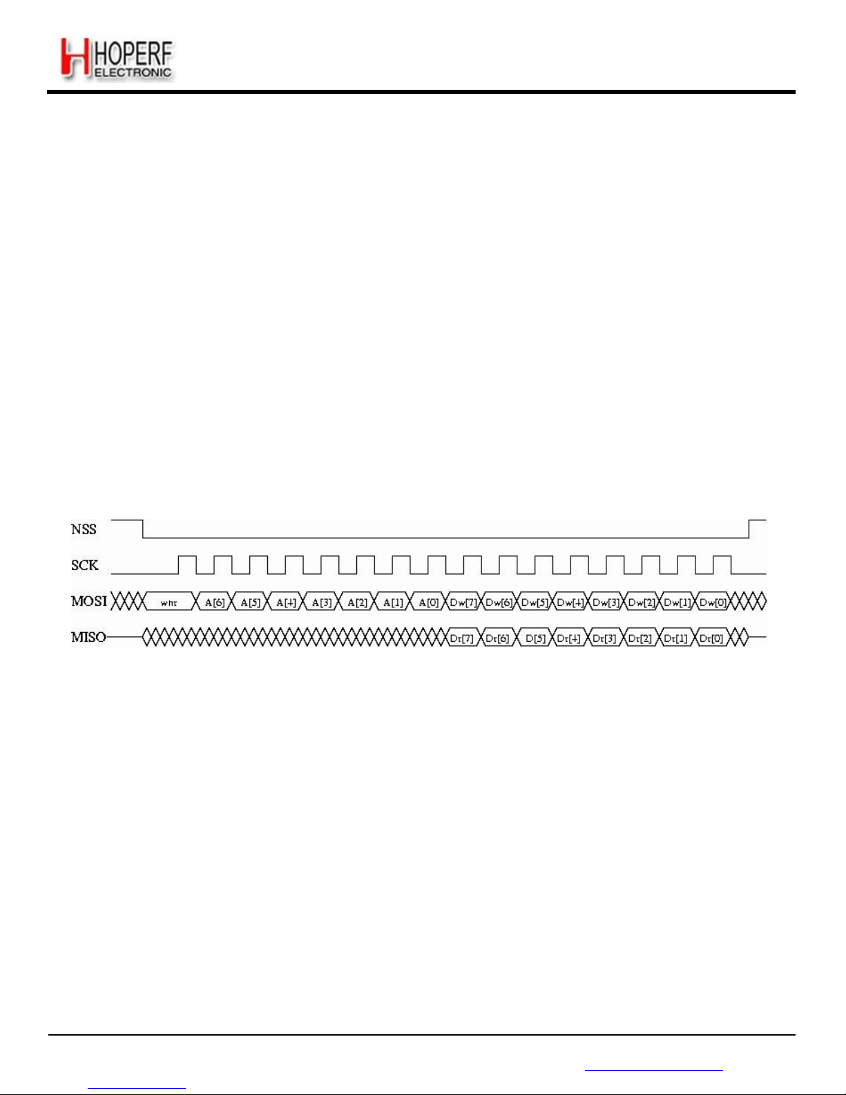
Page 38
RF65
Tel: +86-755-82973805 Fax: +86-755-82973550 E-mail: [email protected] http://www.hoperf.com
ADVANCED COMMUNICATIONS & SENSING DATASHEET
5.2. Control Block Description
5.2.1. SPI Interface
The SPI interface gives access to the configuration register via a synchronous full-duplex protocol corresponding to CPOL
= 0 and CPHA = 0 in Motorola/Freescale nomenclature. Only the slave side is implemented.
Three access modes to the registers are provided:
SINGLE access: an address byte followed by a data byte is sent for a write access whereas an address byte is sent and
a read byte is received for the read access. The NSS pin goes low at the begin of the frame and goes high after the data
byte.
BURST access: the address byte is followed by several data bytes. The address is automatically incremented internally
between each data byte. This mode is available for both read and write accesses. The NSS pin goes low at the
beginning of the frame and stay low between each byte. It goes high only after the last byte transfer.
FIFO access: if the address byte corresponds to the address of the FIFO, then succeeding data byte will address the
FIFO. The address is not automatically incremented but is memorized and does not need to be sent between each data
byte. The NSS pin goes low at the beginning of the frame and stay low between each byte. It goes high only after the
last byte transfer.
Figure below shows a typical SPI single access to a register.
Figure 21. SPI Timing Diagram (single
access)
MOSI is generated by the master on the falling edge of SCK and is sampled by the slave (i.e. this SPI interface) on the
rising edge of SCK. MISO is generated by the slave on the falling edge of SCK.
A transfer always starts by the NSS pin going low. MISO is high impedance when NSS is high.
The first byte is the address byte. It is made of:
wnr bit, which is 1 for write access and 0 for read access
7 bits of address, MSB first
The second byte is a data byte, either sent on MOSI by the master in case of a write access, or received by the master on
MISO in case of read access. The data byte is transmitted MSB first.
Proceeding bytes may be sent on MOSI (for write access) or received on MISO (for read access) without rising NSS and
re-sending the address. In FIFO mode, if the address was the FIFO address then the bytes will be read at the FIFO
address. In Burst mode, if the address was not the FIFO address, then it is automatically incremented at each new byte
received.
Page 39
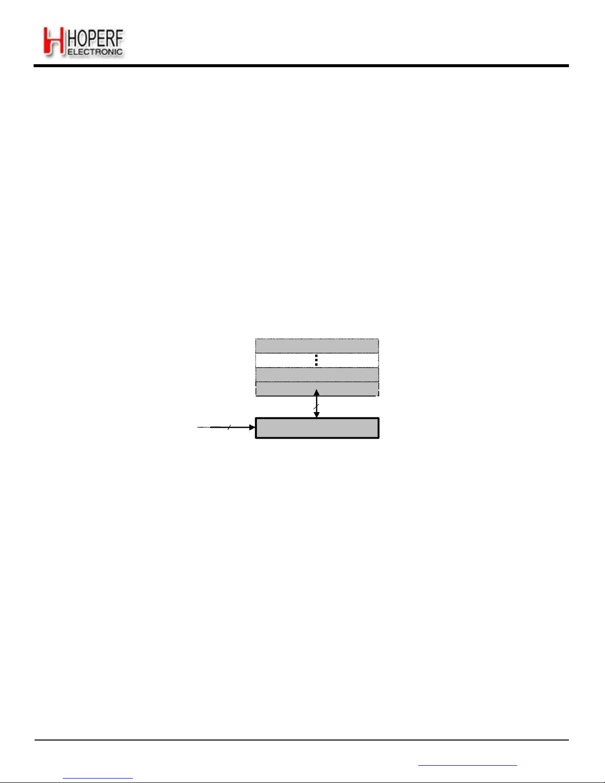
Page 39
RF65
Tel: +86-755-82973805 Fax: +86-755-82973550 E-mail: [email protected] http://www.hoperf.com
ADVANCED COMMUNICATIONS & SENSING DATASHEET
The frame ends when NSS goes high. The next fram e must start with an address byte. The SINGLE access mode is
actually a special case of FIFO / BURST mode with only 1 data byte transferred.
During the write access, the byte transferred from the slave to the master on the MISO line is the value of the written
register before the write operation.
5.2.2. FIFO
5.2.2.1. Overview and Shift Register (SR)
In packet mode of operation, data that has been received is stored in a configurable FIFO (First In First Out) device. It is
accessed via the SPI interface and provides several interrupts for transfer management.
The FIFO is 1 byte wide hence it only performs byte (parallel) operations, whereas the demodulator functions serially. A
shift register is therefore employed to interface the two devices. In Rx the shift register gets bit by bit data from the
demodulator and writes them byte by byte to the FIFO. This is illustrated in Figure 22.
byte1
byte0
FIFO
Rx Data
1
8
SR (8bits)
MSB
LSB
Figure 22. FIFO and Shift Register
(SR)
Note When switching to Sleep mode, the FIFO can only be used once the ModeReady flag is set (quasi immediate from
all modes)
5.2.2.2. Size
The FIFO size is fixed to 66 bytes.
5.2.2.3. Interrupt Sources and Flags
FifoNotEmpty: FifoNotEmpty interrupt source is low when byte 0, i.e. whole FIFO, is empty. Otherwise it is high. Note
that when retrieving data from the FIFO, FifoNotEmpty is updated on NSS falling edge, i.e. when FifoNotEmpty is
updated to low state the currently started read operation must be completed. In other words, FifoNotEmpty state
must be checked after each read operation for a decision on the next one (FifoNotEmpty = 1: more byte(s) to read;
FifoNotEmpty = 0: no more byte to read).
FifoFull: Fifofull interrupt source is high when the last FIFO byte, i.e. the whole FIFO, is full. Otherwise it is low.
FifoOverrunFlag: FifoOverrunFlag is set when a new byte is written by the SR while the FIFO is already full. Data is lost
and the flag should be cleared by writing a 1, note that the FIFO will also be cleared.
FifoLevel: Threshold can be programmed by FifoThreshold in RegFifoThresh. Its behavior is illustrated in figure below.
Page 40
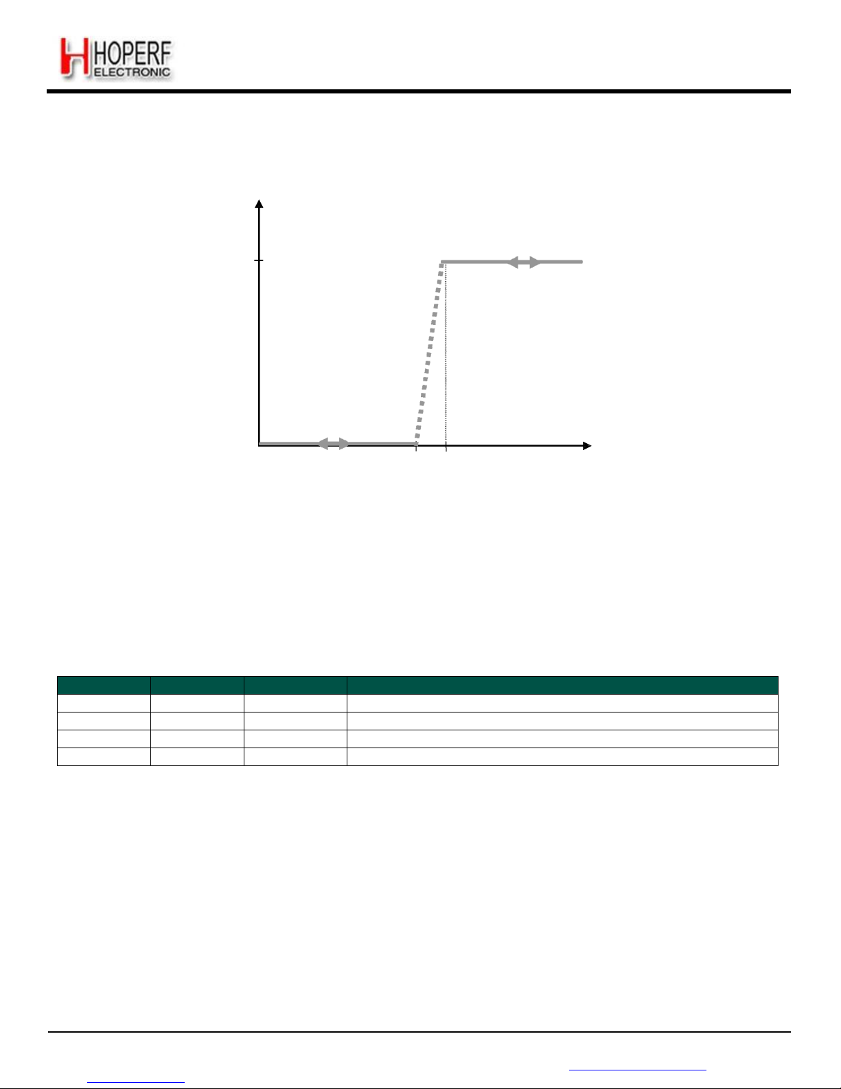
Page 40
RF65
Tel: +86-755-82973805 Fax: +86-755-82973550 E-mail: [email protected] http://www.hoperf.com
ADVANCED COMMUNICATIONS & SENSING DATASHEET
FifoLevel
1
0
B B+1
# of bytes in FIFO
Figure 23. FifoLevel IRQ Source Behavior
5.2.2.4. FIFO Clearing
Table below summarizes the status of the FIFO when switching between different modes
Table 16 Status of FIFO when Switching Between Different Modes of the Chip
From
To
FIFO status
Comments
Stdby
Sleep
Not cleared
Sleep
Stdby
Not cleared
Stdby/Sleep
Rx
Cleared
Rx
Stdby/Sleep
Not cleared
To allow the user to read FIFO in Stdby/Sleep mode after Rx
5.2.3. Sync Word Recognition
5.2.3.1. Overview
Sync word recognition (also called Pattern recognition) is activated by setting SyncOn in RegSyncConfig. The bit
synchronizer must also be activated in continuous mode (automatically done in Packet mode) .
The block behaves like a shift register; it continuously compares the incoming data with its internally programmed Sync
word and sets SyncAddressMatch when a match is detected. This is illustrated in Figure 24 below.
Page 41
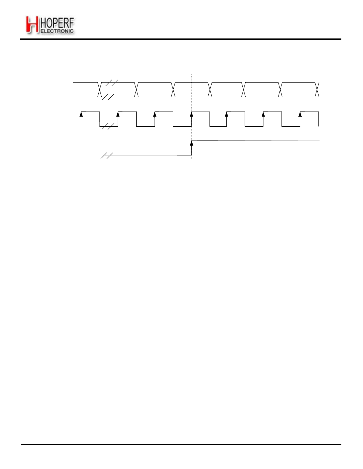
Page 41
RF65
Tel: +86-755-82973805 Fax: +86-755-82973550 E-mail: [email protected] http://www.hoperf.com
ADVANCED COMMUNICATIONS & SENSING DATASHEET
Rx DATA
(NRZ)
Bit N-x =
Sync_value[x]
Bit N-1 =
Sync_value[1]
Bit N =
Sync_value[0]
DCLK
SyncAddressMatch
Figure 24. Sync Word
Recognition
During the comparison of the demodulated data, the first bit received is compared with bit 7 (MSB) of RegSyncValue1 and
the last bit received is compared with bit 0 (LSB) of the last byte whose address is determined by the length of the Sync
word.
When the programmed Sync word is detected the user can assume that this incoming packet is for the node and can be
processed accordingly.
SyncAddressMatch is cleared when leaving Rx or FIFO is emptied.
5.2.3.2. Configuration
Size: Sync word size can be set from 1 to 8 bytes (i.e. 8 to 64 bits) via SyncSize in RegSyncConfig.
Error tolerance: The number of errors tolerated in the Sync word recognition can be set from 0 to 7 bits to via SyncTol.
Value: The Sync word value is configured in SyncValue(63:0).
Note SyncValue choices containing 0x00 bytes are not allowed
5.2.4. Packet Handler
The packet handler is the block used in Packet mode. Its functionality is fully described in section 5.5.
5.2.5. Control
The control block configures and controls the full chip's behavior according to the settings programmed in the configuration
registers.
Page 42
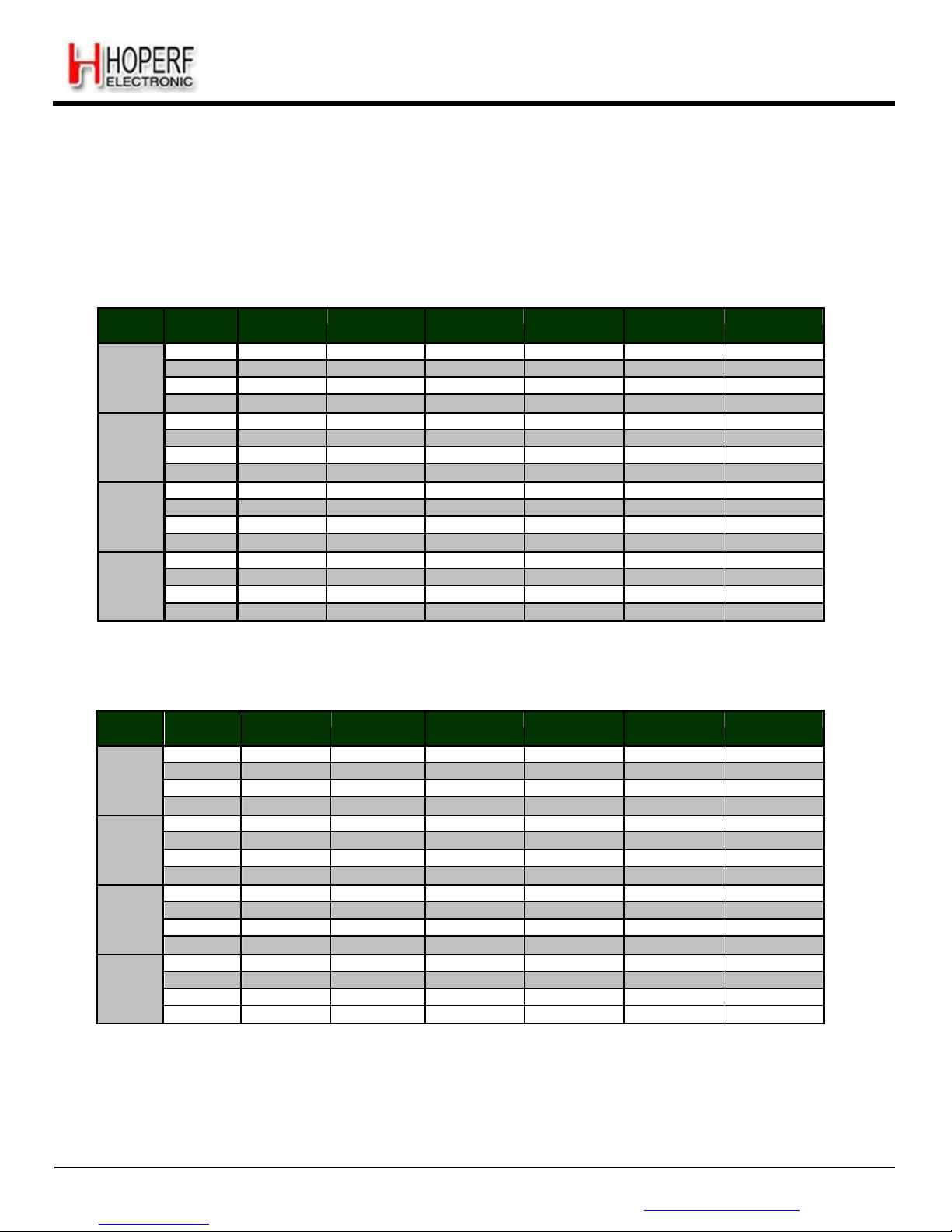
Page 42
RF65
Tel: +86-755-82973805 Fax: +86-755-82973550 E-mail: [email protected] http://www.hoperf.com
ADVANCED COMMUNICATIONS & SENSING DATASHEET
5.3. Digital IO Pins Mapping
Six general purpose IO pins are available on the RF65, and their configuration in Continuous or Packet mode is
controlled through RegDioMapping1 and RegDioMapping2.
5.3.1. DIO Pins Mapping in Continuous Mode
Table 17 DIO Mapping, Continuous Mode
Mode Diox
Mapping
DIO5 DIO4
DIO3
DIO2
DIO1
DIO0
Sleep
00 - - - - - -
01 - - - - - -
10
LowBa
t
Low
Bat
Aut
oMode
-
Low
Bat
LowBa
t
11
ModeReady
- - -
-
ModeReady
St
dby
00
Clk
Out - - - - -
01 - - - - - -
10
LowBa
t
Low
Bat
Aut
oMode
-
Low
Bat
LowBa
t
11
ModeReady
- - -
-
ModeReady
FS 00
Clk
Out - - - - PllLock
01 - - - - - -
10
LowBa
t
Low
Bat
Aut
oMode
-
Low
Bat
LowBa
t
11
ModeReady
Pll
Lock - -
Pll
Lock
ModeReady
Rx
00 ClkOut
Ti
meou
t
Rssi Data Dclk
SyncA
ddress
01
Rssi
RxReady
RxReady Dat
a
RxReady
T
imeout
10
Low
Bat
SyncAd
dress
Aut
oMode
Data
Low
Bat
Rssi
11
ModeReady
Pll
Lock
Timeout
Data
SyncA
ddress
ModeReady
5.3.2. DIO Pins Mapping in Packet Mode
Table 18 DIO Mapping, Packet Mode
Mode Diox
Mapping
DIO5 DIO4 DIO3
DIO2
DIO1
DIO0
Sleep
00 - -
FifoFull
Fif
oNotEmpty
Fif
oLeve
l -
01 - - - -
FifoFull -
10
LowBa
t
Low
Bat
LowBa
t
LowBa
t
Fif
oNo
tEmpty
Low
Bat
11
ModeReady
-
- AutoMode
-
-
St
dby
00 ClkOut -
FifoFull
FifoNotEmpt
y
Fif
oLevel
-
01 - - - -
FifoFull -
10
LowBa
t
Low
Bat
LowBa
t
LowBa
t
Fif
oNo
tEmpty
Low
Bat
11
ModeReady
-
- AutoMode
-
-
FS 00 ClkOut -
FifoFull
FifoNotEmpt
y
Fif
oLevel
-
01 - - - -
FifoFull -
10
LowBa
t
Low
Bat
LowBa
t
LowBa
t
Fif
oNo
tEmpty
Low
Bat
11
ModeReady
Pll
Lock
Pll
Lock
A
utoMode
Pll
Lock
Pll
Lock
Rx
00 ClkOut
Ti
meou
t
FifoFull
FifoNotEmpt
y
Fif
oLevel
CrcOk
01 Data Rssi
Rssi Data FifoFull
Payl
oadReady
10
LowBa
t
RxReady
S
yncAddress
LowBa
t
Fif
oNo
tEmpty
SyncA
ddress
11
ModeReady
Pll
Lock
Pll
Lock
A
utoMode
Timeout
Rssi
Note Received Data is only shown on the Data signal between RxReady and PayloadReady’s rising edges
Page 43
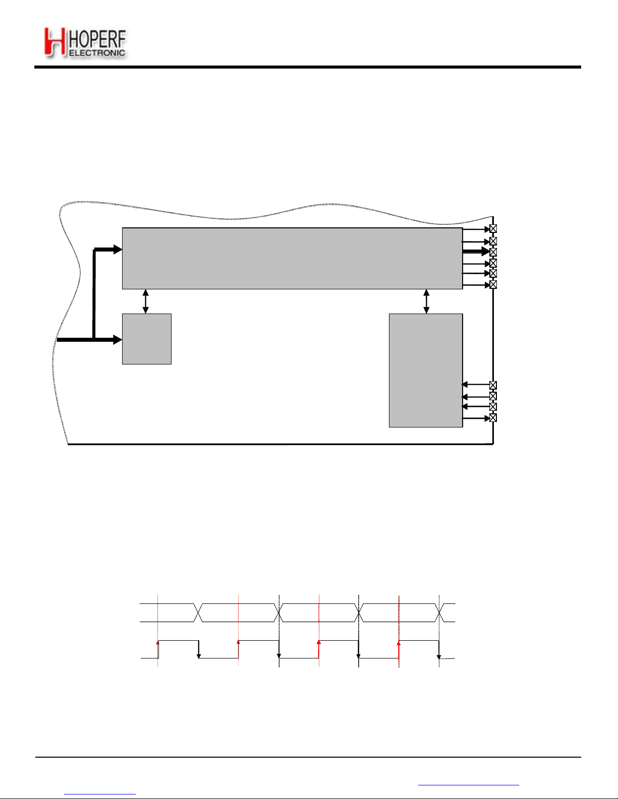
Page 43
RF65
Tel: +86-755-82973805 Fax: +86-755-82973550 E-mail: [email protected] http://www.hoperf.com
ADVANCED COMMUNICATIONS & SENSING DATASHEET
5.4. Continuous Mode
5.4.1. General Description
As illustrated in Figure 25, in Continuous mode the NRZ data from the demodulator is directly accessed by the uC on the
DIO2/DATA pin. The FIFO and packet handler are thus inactive.
Rx
CONTROL
DIO0
DIO1/DCLK
DIO2/DATA
DIO3
DIO4
DIO5
Data
Rx
SYNC
RECOG.
SPI
NSS
SCK
MOSI
MISO
Figure 25. Continuous Mode Conceptual View
5.4.2. Rx Processing
If the bit synchronizer is disabled, the raw demodulator output is made directly available on DATA pin and no DCLK signal
is provided.
Conversely, if the bit synchronizer is enabled, synchronous cleaned data and clock are made available respectively on
DIO2/DATA and DIO1/DCLK pins. DATA is sampled on the rising edge of DCLK and updated on the falling edge as
illustrated below.
DATA
(NRZ)
DCLK
Figure 26. Rx Processing in Continuous
Mode
Note in Continuous mode it is always recommended to enable the bit synchronizer to clean the DATA signal even if
the
DCLK signal is not used by the uC (bit synchronizer is automatically enabled in Packet mode).
Page 44
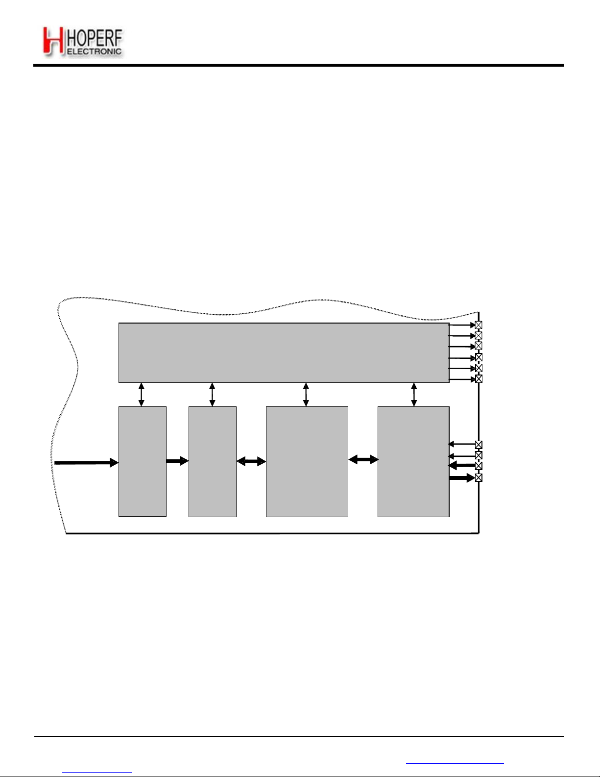
Page 44
RF65
Tel: +86-755-82973805 Fax: +86-755-82973550 E-mail: [email protected] http://www.hoperf.com
ADVANCED COMMUNICATIONS & SENSING DATASHEET
5.5. Packet Mode
5.5.1. General Description
In Packet mode the NRZ data from the demodulator is not directly accessed by the uC but stored in the FIFO and
accessed via the SPI interface.
In addition, the RF65 packet handler performs several packet oriented tasks such as Preamble and Sync word check,
CRC check, dewhitening of data, Manchester decoding, address filtering, AES decryption, etc. This simplifies software and
reduces uC overhead by performing these repetitive tasks within the RF chip itself.
Another important feature is ability to empty the FIFO in Sleep/Stdby mode, ensuring optimum power consumption and
adding more flexibility for the software.
CONTROL
DIO0
DIO1
DIO2
DIO3
DIO4
DIO5
Data
Rx
SYNC
RECOG.
PACKET
HANDLER
FIFO
(+SR)
SPI
NSS
SCK
MOSI
MISO
Figure 27. Packet Mode Conceptual
View
Note The Bit Synchronizer is automatically enabled in Packet mode.
5.5.2. Packet Format
5.5.2.1. Fixed Length Packet Format
Fixed length packet format is selected when bit PacketFormat is set to 0 and PayloadLength is set to any value greater
than 0.
In applications where the packet length is fixed in advance, this mode of operation may be of interest to minimize RF
overhead (no length byte field is required). All nodes should be programmed with the same packet length value.
Page 45
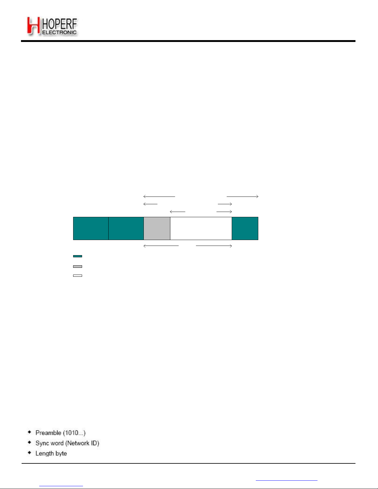
Page 45
RF65
Tel: +86-755-82973805 Fax: +86-755-82973550 E-mail: [email protected] http://www.hoperf.com
ADVANCED COMMUNICATIONS & SENSING DATASHEET
The length of the payload is limited to 255 bytes if AES is not enabled else the message is limited to 64 bytes (i.e. max 65
bytes payload if Address byte is enabled).
The length programmed in PayloadLength relates only to the payload which includes the message and the optional
address byte. In this mode, the payload must contain at least one byte, i.e. address or message byte.
An illustration of a fixed length packet is shown below. It contains the following fields:
Preamble (1010...)
Sync word (Network ID)
Optional Address byte (Node ID)
Message data
Optional 2-bytes CRC checksum
DC free Data
decoding
CRC checksum
calculation
AES
Decryption
Preamble
0 to 65535
bytes
Sync Word
0 to 8 bytes
Address
byte
Message
Up to 255
bytes
CRC
2-bytes
Payload
(min
1
Byte)
Fields processed and removed in Rx
Optional User provided fields which are part of the payload
Message part of the payload
Figure 28. Fixed Length Packet
Format
5.5.2.2. Variable Length Packet Format
Variable length packet format is selected when bit PacketFormat is set to 1.
This mode is useful in applications where the length of the packet is not known in advance and can vary over time. It is then
necessary for the transmitter to send the length information together with each packet in order for the receiver to operate
properly.
In this mode the length of the payload, indicated by the length byte, is given by the first byte of the FIFO and is limited to
255 bytes if AES is not enabled else the message is limited to 64 bytes, i.e. max 66 bytes payload if Address byte is
enabled. Note that the length byte itself is not included in its calculation. In this mode, the payload must contain at least 2
bytes, i.e. length + address or message byte.
An illustration of a variable length packet is shown below. It contains the following fields:
Page 46
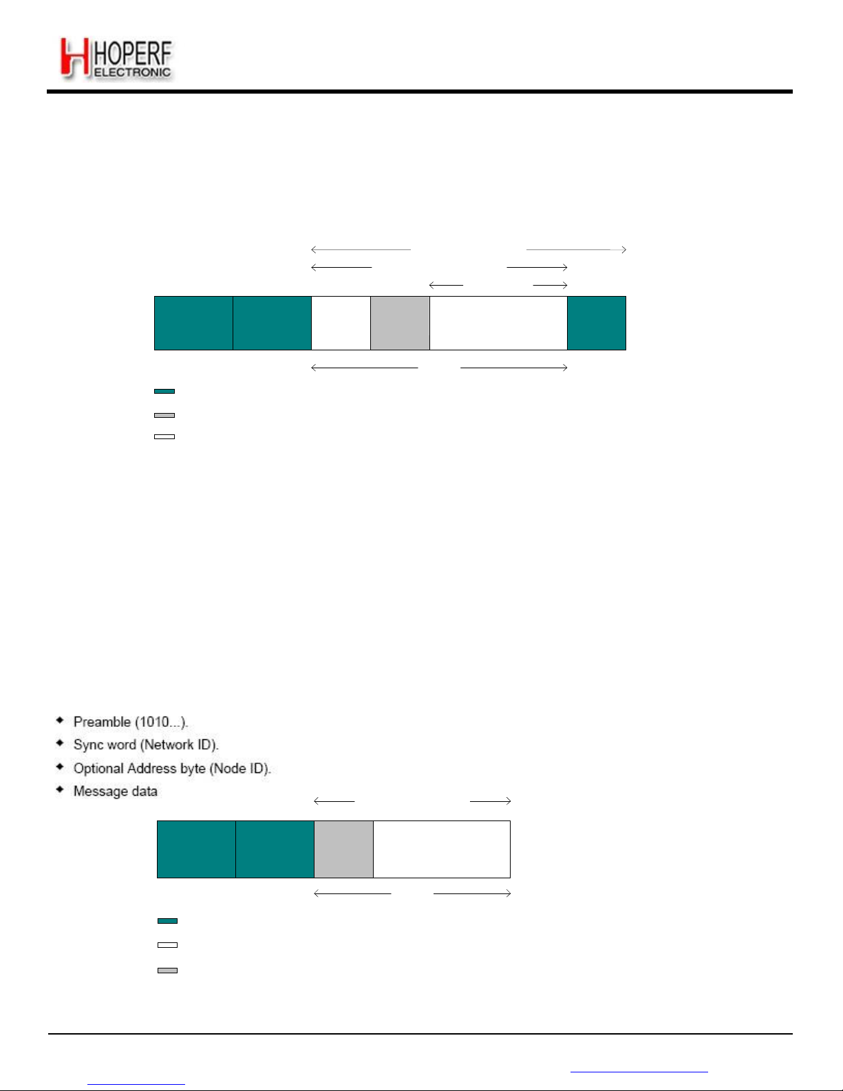
Page 46
RF65
Tel: +86-755-82973805 Fax: +86-755-82973550 E-mail: [email protected] http://www.hoperf.com
ADVANCED COMMUNICATIONS & SENSING DATASHEET
Optional Address byte (Node ID)
Message data
Optional 2-bytes CRC checksum
DC free Data
decoding
CRC checksum
calculation
AES
Decryption
Preamble
0 to 65535
bytes
Sync Word
0 to 8 bytes
Length
byte
Address
byte
Message
Up to 255
bytes
CRC
2-bytes
Fields processed and removed in Rx
Payload
(min 2
bytes)
Optional User provided fields which are part of the payload
Message part of the payload
Figure 29. Variable Length Packet Format
5.5.2.3. Unlimited Length Packet Format
Unlimited length packet format is selected when bit PacketFormat is set to 0 and PayloadLength is set to 0.
The user can then receive packets of arbitrary length and PayloadLength register is not used in Rx modes for counting the
length of the bytes received. This mode is a replacement for the legacy buffered mode in RF63/RF64 transceivers.
The data processing features like Address filtering, Manchester decoding and data dewhitening are not available if the
sync pattern length is set to zero (SyncOn = 0). The CRC detection is also not supported in this mode of the packet
handler. The interrupts like CrcOk & PayloadReady are not available either.
An unlimited length packet shown in is made up of the following fields:
DC free Data decoding
Preamble
0 to 65535
bytes
Sync Word
0 to 8 bytes
Address
byte
Message
unlimited length
Payload
Fields processed and removed in Rx
Message part of the payload
Optional User provided fields which are part of the payload
Figure 30. Unlimited Length Packet Format
Page 47

Page 47
RF65
Tel: +86-755-82973805 Fax: +86-755-82973550 E-mail: [email protected] http://www.hoperf.com
ADVANCED COMMUNICATIONS & SENSING DATASHEET
5.5.3. Processing (without AES)
In Rx mode the packet handler extracts the user payload to the FIFO by performing the following operations:
Receiving the preamble and stripping it off
Detecting the Sync word and stripping it off
Optional DC-free decoding of data
Optionally checking the address byte
Optionally checking CRC and reflecting the result on CrcOk.
Only the payload (including optional address and length fields) is made available in the FIFO.
When the Rx mode is enabled the demodulator receives the preamble followed by the detection of sync word. If fixed
length packet format is enabled then the number of bytes received as the payload is given by the PayloadLength
parameter.
In variable length mode the first byte received after the sync word is interpreted as the length of the received packet. The
internal length counter is initialized to this received length. The PayloadLength register is set to a value which is greater
than the maximum expected length of the received packet. If the received length is greater than the maximum length stored
in PayloadLength register the packet is discarded otherwise the complete packet is received.
If the address check is enabled then the second byte received in case of variable length and first byte in case of fixed
length is the address byte. If the address matches to the one in the NodeAddress field, reception of the data continues
otherwise it's stopped. The CRC check is performed if CrcOn = 1 and the result is available in CrcOk indicating that the
CRC was successful. An interrupt (PayloadReady) is also generated on DIO0 as soon as the payload is available in the
FIFO. The payload available in the FIFO can also be read in Sleep/Standby mode.
If the CRC fails the PayloadReady interrupt is not generated and the FIFO is cleared. This function can be overridden by
setting CrcAutoClearOf f = 1, forcing the availability of PayloadReady interrupt and the payload in the FIFO even if the CRC
fails.
5.5.4. AES
AES is the symmetric-key block cipher that provides the cryptographic capabilities to the receiver. The system proposed
can work with 128-bit long fixed keys. The fixed key is stored in a 16-byte write only user configuration register, which
retains its value in Sleep mode.
As shown in Figure 28 and Figure 29 above the message part of the Packet can be decrypted with the cipher 128- cipher
key stored in the configuration registers.
5.5.4.1. Processing
1. The data received is stored in the FIFO, The address, CRC interrupts are generated as usual because these
parameters were not encrypted.
2. Once the complete packet has been received. The data is read from the FIFO, decrypted and written back to FIFO.
The PayloadReady interrupt is issued once the decrypted data is ready in the FIFO for reading via the SPI interface.
The AES decryption cannot be used on the fly i.e. while receiving data. Thus when AES decryption is enabled, the FIFO
acts as a simple buffer. The decryption is initiated only once the complete packet has been received in the buffer.
The decryption process takes approximately 7.0 us per 16-byte block. Thus for a maximum of 4 blocks (i.e. 64 bytes) it can
take up to 28 us for completing the cryptographic operations.
Page 48

Page 48
RF65
Tel: +86-755-82973805 Fax: +86-755-82973550 E-mail: [email protected] http://www.hoperf.com
ADVANCED COMMUNICATIONS & SENSING DATASHEET
The receiver sees the AES decryption time as a sequential delay before the PayloadReady interrupt is available.
In Fixed length mode the Message part of the payload that can be decrypted can be 64 bytes long. If the address filtering is
enabled, the length of the payload should be at max 65 bytes in this case.
In Variable length mode the Max message size that can be decrypted is also 64 bytes whether address comparison is
enabled or not. Thus, including length byte, the length of the payload is either 65 or 66 bytes (the latter when address
comparison is enabled) at max.
Crc check being performed on encrypted data, CrcOk interrupt will occur "decryption time" before PayloadReady interrupt.
5.5.5. Handling Large Packets
When Payload length exceeds FIFO size (66 bytes) whether in fixed, variable or unlimited length packet format, in addition
to PayloadReady or CrcOk in Rx, the FIFO interrupts/flags can be used as described below:
FIFO must be unfilled "on-the-fly" during Rx to prevent FIFO overrun.
1) Start reading bytes from the FIFO when FifoNotEmpty or FifoThreshold becomes set.
2) Suspend reading from the FIFO if FifoNotEmpty clears before all bytes of the message have been read
3) Continue to step 1 until PayloadReady or CrcOk fires
4) Read all remaining bytes from the FIFO either in Rx or Sleep/Standby mode
Note AES decryption is not feasible on large packets, since all Payload bytes need to be in the FIFO at the same time to
perform decryption
5.5.6. Packet Filtering
RF65's packet handler offers several mechanisms for packet filtering, ensuring that only useful packets are made
available to the uC, reducing significantly system power consumption and software complexity.
5.5.6.1. Sync Word Based
Sync word filtering/recognition is used for identifying the start of the payload and also for network identification. As
previously described, the Sync word recognition block is configured (size, error tolerance, value) in RegSyncValue
registers. This information is used to filter packets in Rx.
Every received packet which does not start with this locally configured Sync word is automatically discarded and no
interrupt is generated.
When the Sync word is detected, payload reception automatically starts and SyncAddressMatch is asserted.
Note Sync Word values containing 0x00 byte(s) are forbidden
Page 49

Page 49
RF65
Tel: +86-755-82973805 Fax: +86-755-82973550 E-mail: [email protected] http://www.hoperf.com
ADVANCED COMMUNICATIONS & SENSING DATASHEET
5.5.6.2. Address Based
Address filtering can be enabled via the AddressFiltering bits. It adds another level of filtering, above Sync word (i.e. Sync
must match first), typically useful in a multi-node networks where a network ID is shared between all nodes (Sync word)
and each node has its own ID (address).
Two address based filtering options are available:
AddressFiltering = 01: Received address field is compared with internal register NodeAddress. If they match then the
packet is accepted and processed, otherwise it is discarded.
AddressFiltering = 10: Received address field is compared with internal registers NodeAddress and BroadcastAddress.
If either is a match, the received packet is accepted and processed, otherwise it is discarded. This additional check with
a constant is useful for implementing broadcast in a multi-node networks
As address filtering requires a Sync Word match, both features share the same interrupt flag SyncAddressMatch.
Please note that the received address byte, as part of the payload, is not stripped off the packet and is made available in
the FIFO.
5.5.6.3. Length Based
In variable length Packet mode, PayloadLength must be programmed with the maximum payload length permitted. If
received length byte is smaller than this maximum then the packet is accepted and processed, otherwise it is discarded.
Please note that the received length byte, as part of the payload, is not stripped off the packet and is made available in the
FIFO.
To disable this function the user should set the value of the PayloadLength to 255.
5.5.6.4. CRC Based
The CRC check is enabled by setting bit CrcOn in RegPacketConfig1. It is used for checking the integrity of the message.
The checksum is calculated on the received payload and compared with the two checksum bytes received. The result of
the comparison is stored in bit CrcOk.
By default, if the CRC check fails then the FIFO is automatically cleared and no interrupt is generated. This filtering function
can be disabled via CrcAutoClearOff bit and in this case, even if CRC fails, the FIFO is not cleared and only PayloadReady
interrupt goes high. Please note that in both cases, the two CRC checksum bytes are stripped off by the packet handler
and only the payload is made available in the FIFO.
The CRC is based on the CCITT polynomial as shown below. This implementation also detects errors due to leading and
trailing zeros.
Page 50
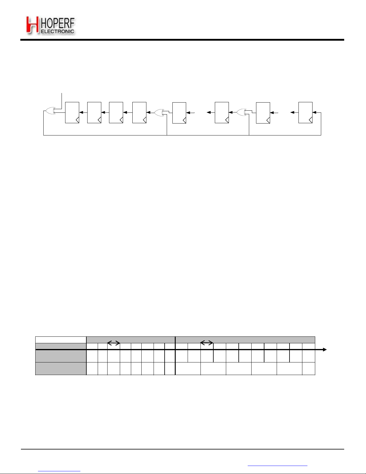
Page 50
RF65
Tel: +86-755-82973805 Fax: +86-755-82973550 E-mail: [email protected] http://www.hoperf.com
ADVANCED COMMUNICATIONS & SENSING DATASHEET
data input
CRC Polynomial =X
16
+ X
12
+ X5 + 1
X
15
X
14 X13 X12
X
11
* * *
X
5
X
4
* * *
X
0
Figure 31. CRC
Implementation
5.5.7. DC-Free Data Mechanisms
The received payload can be de-whitened or Manchester decoded automatically in the RF65 Packet Handler.
Note Only one of the two methods should be enabled at a time.
5.5.7.1. Manchester Decoding
Manchester decoding is enabled if DcFree = 01 and can only be used in Packet mode.
The Manchester data is decoded to NRZ code by decoding "10" as '1' and "01" as '0'.
In this case, the maximum chip rate is the maximum bit rate given in the specifications section and the actual bit rate is half
the chip rate.
Manchester decoding is only applied to the payload and CRC checksum while preamble and Sync word are kept NRZ.
However, the chip rate from preamble to CRC is the same and defined by BitRate in RegBitRate (Chip Rate = Bit Rate
NRZ = 2 x Bit Rate Manchester).
Manchester decoding is thus made transparent for the user, who still retrieves NRZ data from the FIFO.
1/BR
...Sync
1/BR
Payload...
RF chips @ BR ... 1 1 1 0 1 0 0 1 0 0 1 0 1 1 0 1 0 ...
User/NRZ bits
t
Manchester OFF
... 1 1 1 0 1 0 0 1 0 0 1 0 1 1 0 1 0 ...
User/NRZ bits
Manchester ON
... 1 1 1 0 1 0 0 1 0 0 1 1 ...
Figure 32. Manchester
Decoding
5.5.7.2. Data De-Whitening
Another technique called whitening or scrambling is widely used for randomizing the user data before radio transmission.
The data is whitened using a random sequence on the Tx side and de-whitened on the Rx side using the same sequence.
Comparing to Manchester technique it has the advantage of keeping NRZ data rate i.e. actual bit rate is not halved.
Page 51
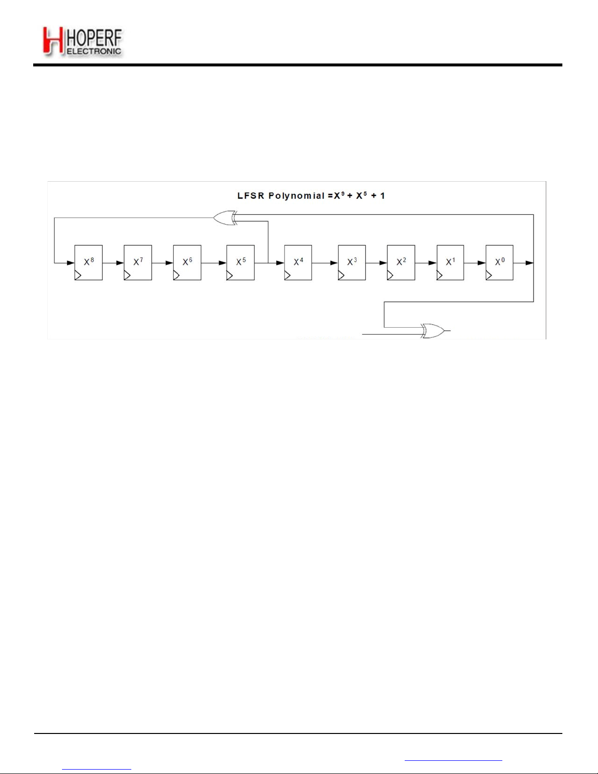
Page 51
RF65
Tel: +86-755-82973805 Fax: +86-755-82973550 E-mail: [email protected] http://www.hoperf.com
ADVANCED COMMUNICATIONS & SENSING DATASHEET
The de-whitening process is enabled if DcFree = 10. The data, including payload and 2-byte CRC checksum, is dewhitened by XORing it with a random sequence generated in a 9-bit LFSR, shown in Figure 33.
Payload de-whitening is thus made transparent for the user, who still retrieves NRZ data from the FIFO.
Received Data
De-whitened Data
Figure 33. Data
De-Whitening
Page 52
Page 52
RF65
Tel: +86-755-82973805 Fax: +86-755-82973550 E-mail: [email protected] http://www.hoperf.com
ADVANCED COMMUNICATIONS & SENSING DATASHEET
6. Configuration and Status Registers
6.1. General Description
Table 19 Registers Summary
Address
Register Name
Reset
(built-in)
Default
(recom
mended)
Description
0x00
RegFifo
0x00
FIFO read/write access
0x01
RegOpMode
0x04
Operating modes of the receiver
0x02
RegDataModul
0x00
Data operation mode and Modulation settings
0x03
RegBitrateMsb
0x1A
Bit Rate setting, Most Significant Bits
0x04
RegBitrateLsb
0x0B
Bit Rate setting, Least Significant Bits
0x05
Reserved05
0x00
-
0x06
Reserved06
0x52
-
0x07
RegFrfMsb
0xE4
RF Carrier Frequency, Most Significant Bits
0x08
RegFrfMid
0xC0
RF Carrier Frequency, Intermediate Bits
0x09
RegFrfLsb
0x00
RF Carrier Frequency, Least Significant Bits
0x0A
RegOsc1
0x41
RC Oscillators Settings
0x0B
RegAfcCtrl
0x00
AFC control in low modulation index situations
0x0C
RegLowBat
0x02
Low Battery Indicator Settings
0x0D
RegListen1
0x92
Listen Mode settings
0x0E
RegListen2
0xF5
Listen Mode Idle duration
0x0F
RegListen3
0x20
Listen Mode Rx duration
0x10
RegVersion
0x23
ID relating the silicon revision
0x11
Reserved11
0x9F
-
0x12
Reserved12
0x09
-
0x13
Reserved13
0x1A
-
0x14
Reserved14
0x40
-
0x15
Reserved15
0xB0
-
0x16
Reserved16
0x7B
-
0x17
Reserved17
0x9B
-
0x18
RegLna
0x08
0x88
LNA settings
0x19
RegRxBw
0x86
0x55
Channel Filter BW Control
Page 53
Page 53
RF65
Tel: +86-755-82973805 Fax: +86-755-82973550 E-mail: [email protected] http://www.hoperf.com
ADVANCED COMMUNICATIONS & SENSING DATASHEET
Address
Register Name
Reset
(built-in)
Default
(recom
mended)
Description
0x1A
RegAfcBw
0x8A
0x8B
Channel Filter BW control during the AFC routine
0x1B
RegOokPeak
0x40
OOK demodulator selection and control in peak mode
0x1C
RegOokAvg
0x80
Average threshold control of the OOK demodulator
0x1D
RegOokFix
0x06
Fixed threshold control of the OOK demodulator
0x1E
RegAfcFei
0x10
AFC and FEI control and status
0x1F
RegAfcMsb
0x00
MSB of the frequency correction of the AFC
0x20
RegAfcLsb
0x00
LSB of the frequency correction of the AFC
0x21
RegFeiMsb
0x00
MSB of the calculated frequency error
0x22
RegFeiLsb
0x00
LSB of the calculated frequency error
0x23
RegRssiConfig
0x02
RSSI-related settings
0x24
RegRssiValue
0xFF
RSSI value in dBm
0x25
RegDioMapping1
0x00
Mapping of pins DIO0 to DIO3
0x26
RegDioMapping2
0x05
0x07
Mapping of pins DIO4 and DIO5, ClkOut frequency
0x27
RegIrqFlags1
0x80
Status register: PLL Lock state, Timeout, RSSI > Threshold...
0x28
RegIrqFlags2
0x00
Status register: FIFO handling flags, Low Battery detection...
0x29
RegRssiThresh
0xFF
0xE4
RSSI Threshold control
0x2A
RegRxTimeout1
0x00
Timeout duration between Rx request and RSSI detection
0x2B
RegRxTimeout2
0x00
Timeout duration between RSSI detection and PayloadReady
0x2C
Reserved2C
0x00
-
0x2D
Reserved2D
0x03
-
0x2E
RegSyncConfig
0x98
Sync Word Recognition control
0x2F-0x36
RegSyncValue1-8
0x00
0x01
Sync Word bytes, 1 through 8
0x37
RegPacketConfig1
0x10
Packet mode settings
0x38
RegPayloadLength
0x40
Payload length setting
0x39
RegNodeAdrs
0x00
Node address
0x3A
RegBroadcastAdrs
0x00
Broadcast address
0x3B
RegAutoModes
0x00
Auto modes settings
0x3C
RegFifoThresh
0x0F
0x8F
Fifo threshold
0x3D
RegPacketConfig2
0x02
Packet mode settings
Page 54
Page 54
RF65
Tel: +86-755-82973805 Fax: +86-755-82973550 E-mail: [email protected] http://www.hoperf.com
ADVANCED COMMUNICATIONS & SENSING DATASHEET
Address
Register Name
Reset
(built-in)
Default
(recom
mended)
Description
0x3E-0x4D
RegAesKey1-16
0x00
16 bytes of the cypher key
0x4E
RegTemp1
0x01
Temperature Sensor control
0x4F
RegTemp2
0x00
Temperature readout
0x58
RegTestLna
0x1B
Sensitivity boost
0x6F
RegTestDagc
0x00
0x30
Fading Margin Improvement
0x71
RegTestAfc
0x00
AFC offset for low modulation index AFC
0x50 +
RegTest
-
Internal test registers
Note - Reset values are automatically refreshed in the chip at Power On Reset
- Default values are the HopeRF recommended register values, optimizing the device operation
- Registers for which the Default value differs from the Reset value are denoted by a * in the tables of section 6
Page 55
Page 55
RF65
Tel: +86-755-82973805 Fax: +86-755-82973550 E-mail: [email protected] http://www.hoperf.com
ADVANCED COMMUNICATIONS & SENSING DATASHEET
6.2. Common Configuration Registers
Table 20 Common Configuration Registers
Name
(Address)
Bits
Variable Name
Mode
Default
Value
Description
RegFifo
(0x00)
7-0
Fifo
rw
0x00
FIFO data output
RegOpMode
(0x01)
7
SequencerOff
rw
0
Controls the automatic Sequencer (see section 4.2 ):
0→ Operating mode as selected with Mode bits in
RegOpMode is automatically reached with the Sequencer
1→ Mode is forced by the user
6
ListenOn
rw
0
Enables Listen mode:
0 → Off (see section 4.3)
1→ On
5
ListenAbort
w
0
Aborts Listen mode when set together with ListenOn=0
and new Mode selection in 1 SPI access (see section 4.3)
Always reads 0.
4-2
Mode
rw
001
Receiver‟s operating modes:
000→ sleep mode (SLEEP)
001→ standby mode (STDBY)
010→ frequency synthesizer mode (FS)
100→ receiver mode (RX)
others→ reserved
Reads the value corresponding to the current chip mode
1-0 - r
00
unused
RegDataModul
(0x02)
7 - r
0
unused
6-5
DataMode
rw
00
Data processing mode:
00→ Packet mode
01→ reserved
10→ Continuous mode with bit synchronizer
11→ Continuous mode without bit synchronizer
4-3
ModulationType
rw
00
Modulation scheme:
00→ FSK
01→ OOK
10 - 11→ reserved
2-0 - r
000
unused
RegBitrateMsb
(0x03)
7-0
BitRate(15:8)
rw
0x1a
MSB of Bit Rate (Chip Rate when Manchester encoding is
enabled)
RegBitrateLsb
(0x04)
7-0
BitRate(7:0)
rw
0x0b
LSB of Bit Rate (Chip Rate if Manchester encoding is
enabled)
BitRate =
--------F----X----O-----S---C---------BitRate(15,0)
Default value: 4.8 kb/s
Reserved05
(0x05)
7-0 - r
0x00
unused
Reserved06
(0x06)
7-0 - r
0x52
unused
RegFrfMsb
(0x07)
7-0
Frf(23:16)
rw
0xe4
MSB of the RF Local Oscillator
RegFrfMid
(0x08)
7-0
Frf(15:8)
rw
0xc0
Middle byte of the RF Local Oscillator
Page 56
Page 56
RF65
Tel: +86-755-82973805 Fax: +86-755-82973550 E-mail: [email protected] http://www.hoperf.com
ADVANCED COMMUNICATIONS & SENSING DATASHEET
RegFrfLsb
(0x09)
7-0
Frf(7:0)
rw
RegOsc1
(0x0A)
7
RcCalStart
w
0
Triggers the calibration of the RC oscillator when set.
Always reads 0. RC calibration must be triggered in
Standby mode.
6
RcCalDone
r
1
0→ RC calibration in progress
1→ RC calibration is over
5-0 - r
000001
unused
RegAfcCtrl
(0x0B)
7-6 - r
00
unused
5
AfcLowBetaOn
rw
0
Improved AFC routine for signals with modulation index
lower than 2. Refer to section 3.4.17 for details
0→ Standard AFC routine
1→ Improved AFC routine
4-0 - r
00000
unused
RegLowBat
(0x0C)
7-5 - r
000
unused
4
LowBatMonitor
rw
-
Real-time (not latched) output of the Low Battery detector,
when enabled.
3
LowBatOn
rw
0
Low Battery detector enable signal
0→ LowBat off
1→ LowBat on
2-0
LowBatTrim
rw
010
Trimming of the LowBat threshold:
000→ 1.695 V 001→ 1.764 V
010→ 1.835 V 011→ 1.905 V
100→ 1.976 V 101→ 2.045 V
110→ 2.116 V 111→ 2.185 V
RegListen1
(0x0D)
7-6
ListenResolIdle
rw
10
Resolution of Listen modes timings (calibrated RC osc):
0101→ 64 us
1010→ 4.1 ms
1111→ 262 ms
Others→ reserved
5-4
ListenResolRx
rw
01
Resolution of Listen mode Rx time (calibrated RC osc):
00→ reserved
01→ 64 us
10→ 4.1 ms
11→ 262 ms
3
ListenCriteria
rw
0
Criteria for packet acceptance in Listen mode:
0→ signal strength is above RssiThreshold
1→ signal strength is above RssiThreshold and
SyncAddress matched
2-1
ListenEnd
rw
01
Action taken after acceptance of a packet in Listen mode:
00→ chip stays in Rx mode. Listen mode stops and must
be disabled (see section 4.3).
01→ chip stays in Rx mode until PayloadReady or
Timeout interrupt occurs. It then goes to the mode defined
by Mode. Listen mode stops and must be disabled (see
section 4.3).
10→ chip stays in Rx mode until PayloadReady or
Timeout interrupt occurs. Listen mode then resumes in
Idle state. FIFO content is lost at next Rx wakeup.
11→ Reserved
0 - r
0
unused
Page 57
Page 57
RF65
Tel: +86-755-82973805 Fax: +86-755-82973550 E-mail: [email protected] http://www.hoperf.com
ADVANCED COMMUNICATIONS & SENSING DATASHEET
RegListen2
(0x0E)
7-0
ListenCoefIdle
rw
0xf5
Duration of the Idle phase in Listen mode.
t
ListenIdle
=
ListenCoefIdle
⋅ ListenResolIdle
RegListen3
(0x0F)
7-0
ListenCoefRx
rw
0x20
Duration of the Rx phase in Listen mode (startup time
included, see section 4.2.1)
t
ListenRx
=
ListenCoefRx
⋅ ListenResolRx
RegVersion
(0x10)
7-0
Version
r
0x23
Version code of the chip. Bits 7-4 give the full revision
number; bits 3-0 give the metal mask revision number.
Page 58
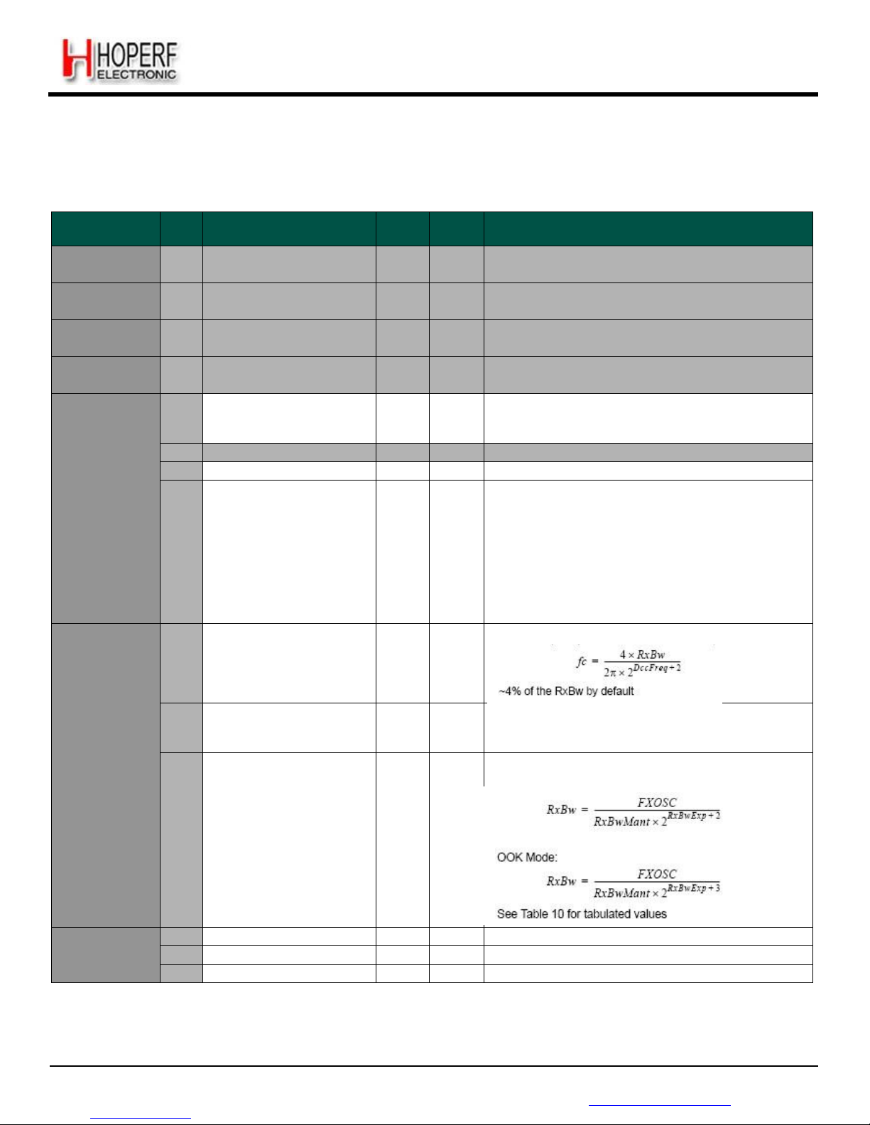
Page 58
RF65
Tel: +86-755-82973805 Fax: +86-755-82973550 E-mail: [email protected] http://www.hoperf.com
ADVANCED COMMUNICATIONS & SENSING DATASHEET
6.3. Receiver Registers
Table 21 Receiver Registers
Name
(Address)
Bits
Variable Name
Mode
Default
Value
Description
Reserved14
(0x14)
7-0 - r
0x40
unused
Reserved15
(0x15)
7-0 - r
0xB0
unused
Reserved16
(0x16)
7-0 - r
0x7B
unused
Reserved17
(0x17)
7-0 - r
0x9B
unused
RegLna
(0x18)
7
LnaZin
rw
1
*
LNA‟s input impedance
0→ 50 ohms
1→ 200 ohms
6 - r
0
unused
5-3
LnaCurrentGain
r
001
Current LNA gain, set either manually, or by the AGC
2-0
LnaGainSelect
rw
000
LNA gain setting:
000→ gain set by the internal AGC loop
001→ G1 = highest gain
010→ G2 = highest gain – 6 dB
011→ G3 = highest gain – 12 dB
100→ G4 = highest gain – 24 dB
101→ G5 = highest gain – 36 dB
110→ G6 = highest gain – 48 dB
111→ reserved
RegRxBw
(0x19)
7-5
DccFreq
rw
010
*
Cut-off frequency of the DC offset canceller (DCC):
4-3
RxBwMant
rw
10
*
Channel filter bandwidth control:
00→ RxBwMant = 16 10→ RxBwMant = 24
01→ RxBwMant = 20 11→ reserved
2-0
RxBwExp
rw
101
*
Channel filter bandwidth control:
FSK Mode:
RegAfcBw
(0x1A)
7-5
DccFreqAfc
rw
100
DccFreq parameter used during the AFC
4-3
RxBwMantAfc
rw
01
RxBwMant parameter used during the AFC
2-0
RxBwExpAfc
rw
011 *
RxBwExp parameter used during the AFC
Page 59
Page 59
RF65
Tel: +86-755-82973805 Fax: +86-755-82973550 E-mail: [email protected] http://www.hoperf.com
ADVANCED COMMUNICATIONS & SENSING DATASHEET
RegOokPeak
(0x1B)
7-6
OokThreshType
rw
01
Selects type of threshold in the OOK data slicer:
00→ fixed 10→ average
01→ peak 11→ reserved
5-3
OokPeakTheshStep
rw
000
Size of each decrement of the RSSI threshold in the OOK
demodulator:
000→ 0.5 dB 001→ 1.0 dB
010→ 1.5 dB 011→ 2.0 dB
100→ 3.0 dB 101→ 4.0 dB
110→ 5.0 dB 111→ 6.0 dB
2-0
OokPeakThreshDec
rw
000
Period of decrement of the RSSI threshold in the OOK
demodulator:
000→ once per chip 001→ once every 2 chips
010→ once every 4 chips 011→ once every 8 chips
100→ twice in each chip 101→ 4 times in each chip
110→ 8 times in each chip 111→ 16 times in each chip
RegOokAvg
(0x1C)
7-6
OokAverageThreshFilt
rw
10
Filter coefficients in average mode of the OOK
demodulator:
00→ fC ≈ chip rate / 32.π
01→ fC ≈ chip rate / 8.π
10→ fC ≈ chip rate / 4.π
11→ fC ≈ chip rate / 2.π
5-0 - r
000000
unused
RegOokFix
(0x1D)
7-0
OokFixedThresh
rw
0110
(6dB)
Fixed threshold value (in dB) in the OOK demodulator.
Used when OokThresType = 00
RegAfcFei
(0x1E)
7 - r
0
unused
6
FeiDone
r
0
0→ FEI is on-going
1→ FEI finished
5
FeiStart w 0
Triggers a FEI measurement when set. Always reads 0.
4
AfcDone
r
1
0→ AFC is on-going
1→ AFC has finished
3
AfcAutoclearOn
rw
0
Only valid if AfcAutoOn is set
0→ AFC register is not cleared before a new AFC phase
1→ AFC register is cleared before a new AFC phase
2
AfcAutoOn
rw
0
0→ AFC is performed each time AfcStart is set
1→ AFC is performed each time Rx mode is entered
1
AfcClear
w
0
Clears the AfcValue if set in Rx mode. Always reads 0
0
AfcStart
w
0
Triggers an AFC when set. Always reads 0.
RegAfcMsb
(0x1F)
7-0
AfcValue(15:8)
r
0x00
MSB of the AfcValue, 2‟s complement format
RegAfcLsb
(0x20)
7-0
AfcValue(7:0)
r
0x00
LSB of the AfcValue, 2‟s complement format
Frequency correction = AfcValue x Fstep
RegFeiMsb
(0x21)
7-0
FeiValue(15:8)
r
-
MSB of the measured frequency offset, 2‟s complement
RegFeiLsb
(0x22)
7-0
FeiValue(7:0)
r
-
LSB of the measured frequency offset, 2‟s complement
Frequency error = FeiValue x Fstep
RegRssiConfig
(0x23)
7-2 - r
000000
unused
1
RssiDone
r
1
0→ RSSI is on-going
1→ RSSI sampling is finished, result available
0
RssiStart
w
0
Trigger a RSSI measurement when set. Always reads 0.
RegRssiValue
(0x24)
7-0
RssiValue
r
0xFF
Absolute value of the RSSI in dBm, 0.5dB steps.
RSSI = -RssiValue/2 [dBm]
Page 60
Page 60
RF65
Tel: +86-755-82973805 Fax: +86-755-82973550 E-mail: [email protected] http://www.hoperf.com
ADVANCED COMMUNICATIONS & SENSING DATASHEET
6.4. IRQ and Pin Mapping Registers
Table 22 IRQ and Pin Mapping Registers
Name
(Address)
Bits
Variable Name
Mode
Default
Value
Description
RegDioMapping1
(0x25)
7-6
Dio0Mapping
rw
00
Mapping of pins DIO0 to DIO5
See Table 17 for mapping in Continuous mode
See Table 18 for mapping in Packet mode
5-4
Dio1Mapping
rw
00
3-2
Dio2Mapping
rw
00
1-0
Dio3Mapping
rw
00
RegDioMapping2
(0x26)
7-6
Dio4Mapping
rw
00
5-4
Dio5Mapping
rw
00
3 - r
0
unused
2-0
ClkOut
rw
111
*
Selects CLKOUT frequency:
000→ FXOSC
001→ FXOSC / 2
010→ FXOSC / 4
011→ FXOSC / 8
100→ FXOSC / 16
101→ FXOSC / 32
110→ RC (automatically enabled)
111→ OFF
RegIrqFlags1
(0x27)
7
ModeReady
r
1
Set when the operation mode requested in Mode, is ready
- Sleep: Entering Sleep mode
- Standby: XO is running
- FS: PLL is locked
- Rx: RSSI sampling starts
Cleared when changing operating mode.
6
RxReady
r
0
Set in Rx mode, after RSSI, AGC and AFC.
Cleared when leaving Rx.
5 - r
0
unused
4
PllLock r 0
Set (in FS and Rx) when the PLL is locked.
Cleared when it is not.
3
Rssi
rwc
0
Set in Rx when the RssiValue exceeds RssiThreshold.
Cleared when leaving Rx.
2
Timeout
r
0
Set when a timeout occurs (see TimeoutRxStart and
TimeoutRssiThresh)
Cleared when leaving Rx or FIFO is emptied.
1
AutoMode
r
0
Set when entering Intermediate mode.
Cleared when exiting Intermediate mode.
Please note that in Sleep mode a small delay can be
observed between AutoMode interrupt and the
corresponding enter/exit condition.
0
SyncAddressMatch
r/rwc
0
Set when Sync and Address (if enabled) are detected.
Cleared when leaving Rx or FIFO is emptied.
This bit is read only in Packet mode, rwc in Continuous
mode
Page 61
Page 61
RF65
Tel: +86-755-82973805 Fax: +86-755-82973550 E-mail: [email protected] http://www.hoperf.com
ADVANCED COMMUNICATIONS & SENSING DATASHEET
RegIrqFlags2
(0x28)
7
FifoFull r 0
Set when FIFO is full (i.e. contains 66 bytes), else
cleared.
6
FifoNotEmpty
r
0
Set when FIFO contains at least one byte, else cleared
5
FifoLevel
r
0
Set when the number of bytes in the FIFO strictly exceeds
FifoThreshold, else cleared.
4
FifoOverrun
rwc
0
Set when FIFO overrun occurs. (except in Sleep mode)
Flag(s) and FIFO are cleared when this bit is set. The
FIFO then becomes immediately available for the next
reception.
3 - r
0
unused
2
PayloadReady
r
0
Set in Rx when the payload is ready (i.e. last byte
received and CRC, if enabled and CrcAutoClearOff is
cleared, is Ok). Cleared when FIFO is empty.
1
CrcOk r 0
Set in Rx when the CRC of the payload is Ok. Cleared
when FIFO is empty.
0
LowBat
rwc
-
Set when the battery voltage drops below the Low Battery
threshold. Cleared only when set by the user.
RegRssiThresh
(0x29)
7-0
RssiThreshold
rw
0xE4
*
RSSI trigger level for Rssi interrupt :
- RssiThreshold / 2 [dBm]
RegRxTimeout1
(0x2A)
7-0
TimeoutRxStart
rw
0x00
Timeout interrupt is generated TimeoutRxStart*16*T
bit
after switching to Rx mode if Rssi interrupt doesn‟t occur
(i.e. RssiValue > RssiThreshold)
0x00: TimeoutRxStart is disabled
RegRxTimeout2
(0x2B)
7-0
TimeoutRssiThresh
rw
0x00
Timeout interrupt is generated TimeoutRssiThresh*16*T
bit
after Rssi interrupt if PayloadReady interrupt doesn‟t
occur.
0x00: TimeoutRssiThresh is disabled
Page 62
Page 62
RF65
Tel: +86-755-82973805 Fax: +86-755-82973550 E-mail: [email protected] http://www.hoperf.com
ADVANCED COMMUNICATIONS & SENSING DATASHEET
6.5. Packet Engine Registers
Table 23 Packet Engine Registers
Name
(Address)
Bits
Variable Name
Mode
Default
Value
Description
Reserved2C
(0x2c)
7-0 - rw
0x00
unused
Reserved2D
(0x2d)
7-0 - rw
0x03
unused
RegSyncConfig
(0x2e)
7
SyncOn
rw
1
Enables the Sync word detection:
0→ Off
1→ On
6
FifoFillCondition
rw
0
FIFO filling condition:
0→ if SyncAddress interrupt occurs
1→ as long as FifoFillCondition is set
5-3
SyncSize
rw
011
Size of the Sync word:
(SyncSize + 1) bytes
2-0
SyncTol
rw
000
Number of tolerated bit errors in Sync word
RegSyncValue1
(0x2f)
7-0
SyncValue(63:56)
rw
0x01
*
1
st
byte of Sync word. (MSB byte)
Used if SyncOn is set.
RegSyncValue2
(0x30)
7-0
SyncValue(55:48)
rw
0x01
*
2
nd
byte of Sync word
Used if SyncOn is set and (SyncSize +1) >= 2.
RegSyncValue3
(0x31)
7-0
SyncValue(47:40)
rw
0x01
*
3
rd
byte of Sync word.
Used if SyncOn is set and (SyncSize +1) >= 3.
RegSyncValue4
(0x32)
7-0
SyncValue(39:32)
rw
0x01
*
4
th
byte of Sync word.
Used if SyncOn is set and (SyncSize +1) >= 4.
RegSyncValue5
(0x33)
7-0
SyncValue(31:24)
rw
0x01
*
5
th
byte of Sync word.
Used if SyncOn is set and (SyncSize +1) >= 5.
RegSyncValue6
(0x34)
7-0
SyncValue(23:16)
rw
0x01
*
6
th
byte of Sync word.
Used if SyncOn is set and (SyncSize +1) >= 6.
RegSyncValue7
(0x35)
7-0
SyncValue(15:8)
rw
0x01
*
7
th
byte of Sync word.
Used if SyncOn is set and (SyncSize +1) >= 7.
RegSyncValue8
(0x36)
7-0
SyncValue(7:0)
rw
0x01
*
8
th
byte of Sync word.
Used if SyncOn is set and (SyncSize +1) = 8.
Page 63
Page 63
RF65
Tel: +86-755-82973805 Fax: +86-755-82973550 E-mail: [email protected] http://www.hoperf.com
ADVANCED COMMUNICATIONS & SENSING DATASHEET
RegPacketConfig1
(0x37)
7
PacketFormat
rw
0
Defines the packet format used:
0→ Fixed length
1→ Variable length
6-5
DcFree
rw
00
Defines DC-free decoding performed:
00→ None (Off)
01→ Manchester
10→ Whitening
11→ reserved
4
CrcOn
rw
1
Enables CRC check:
0→ Off
1→ On
3
CrcAutoClearOff
rw
0
Defines the behavior of the packet handler when CRC
check fails:
0→ Clear FIFO and restart new packet reception. No
PayloadReady interrupt issued.
1→ Do not clear FIFO. PayloadReady interrupt issued.
2-1
AddressFiltering
rw
00
Defines address based filtering in Rx:
00→ None (Off)
01→ Address field must match NodeAddress
10→ Must match NodeAddress or BroadcastAddress
11→ reserved
0 - rw
0
unused
RegPayloadLength
(0x38)
7-0
PayloadLength
rw
0x40
If PacketFormat = 0 (fixed), payload length.
If PacketFormat = 1 (variable), max length in Rx
RegNodeAdrs
(0x39)
7-0
NodeAddress
rw
0x00
Node address used in address filtering.
RegBroadcastAdrs
(0x3A)
7-0
BroadcastAddress
rw
0x00
Broadcast address used in address filtering.
RegAutoModes
(0x3B)
7-5
EnterCondition
rw
000
Interrupt condition for entering the intermediate mode:
000→ None (AutoModes Off)
001→ Rising edge of FifoNotEmpty
010→ Rising edge of FifoLevel
011→ Rising edge of CrcOk
100→ Rising edge of PayloadReady
101→ Rising edge of SyncAddress
110→ Reserved
111→ Falling edge of FifoNotEmpty (i.e. FIFO empty)
4-2
ExitCondition
rw
000
Interrupt condition for exiting the intermediate mode:
000→ None (AutoModes Off)
001→ Falling edge of FifoNotEmpty (i.e. FIFO empty)
010→ Rising edge of FifoLevel or Timeout
011→ Rising edge of CrcOk or Timeout
100→ Rising edge of PayloadReady or Timeout
101→ Rising edge of SyncAddress or Timeout
110→ Reserved
111→ Rising edge of Timeout
1-0
IntermediateMode
rw
00
Intermediate mode:
00→ Sleep mode (SLEEP)
01→ Standby mode (STDBY)
10→ Receiver mode (RX)
11→ Reserved
RegFifoThresh
(0x3C)
7 - rw
1
*
unused
6-0
FifoThreshold
rw
0001111
Used to trigger FifoLevel interrupt.
Page 64
Page 64
RF65
Tel: +86-755-82973805 Fax: +86-755-82973550 E-mail: [email protected] http://www.hoperf.com
ADVANCED COMMUNICATIONS & SENSING DATASHEET
RegPacketConfig2
(0x3D)
7-4
InterPacketRxDelay
rw
0000
After PayloadReady occurred, defines the delay between
FIFO empty and the start of a new RSSI phase for next
packet. Must match the transmitter‟s PA ramp-down time.
- Tdelay = 0 if InterpacketRxDelay >= 12
- Tdelay = (2
InterpacketRxDelay
) / BitRate otherwise
3 - rw
0
unused
2
RestartRx
w
0
Forces the Receiver in WAIT mode, in Continuous Rx
mode.
Always reads 0.
1
AutoRxRestartOn
rw
1
Enables automatic Rx restart (RSSI phase) after
PayloadReady occurred and packet has been completely
read from FIFO:
0→ Off. RestartRx can be used.
1→ On. Rx auto. restart after InterPacketRxDelay.
0
AesOn
rw
0
Enable the AES decryption:
0→ Off
1→ On (payload limited to 66 bytes maximum)
RegAesKey1
(0x3E)
7-0
AesKey(127:120)
w
0x00
1
st
byte of cipher key (MSB byte)
RegAesKey2
(0x3F)
7-0
AesKey(119:112)
w
0x00
2
nd
byte of cipher key
RegAesKey3
(0x40)
7-0
AesKey(111:104)
w
0x00
3
rd
byte of cipher key
RegAesKey4
(0x41)
7-0
AesKey(103:96)
w
0x00
4
th
byte of cipher key
RegAesKey5
(0x42)
7-0
AesKey(95:88)
w
0x00
5
th
byte of cipher key
RegAesKey6
(0x43)
7-0
AesKey(87:80)
w
0x00
6
th
byte of cipher key
RegAesKey7
(0x44)
7-0
AesKey(79:72)
w
0x00
7
th
byte of cipher key
RegAesKey8
(0x45)
7-0
AesKey(71:64)
w
0x00
8
th
byte of cipher key
RegAesKey9
(0x46)
7-0
AesKey(63:56)
w
0x00
9
th
byte of cipher key
RegAesKey10
(0x47)
7-0
AesKey(55:48)
w
0x00
10
th
byte of cipher key
RegAesKey11
(0x48)
7-0
AesKey(47:40)
w
0x00
11
th
byte of cipher key
RegAesKey12
(0x49)
7-0
AesKey(39:32)
w
0x00
12
th
byte of cipher key
RegAesKey13
(0x4A)
7-0
AesKey(31:24)
w
0x00
13
th
byte of cipher key
RegAesKey14
(0x4B)
7-0
AesKey(23:16)
w
0x00
14
th
byte of cipher key
RegAesKey15
(0x4C)
7-0
AesKey(15:8)
w
0x00
15
th
byte of cipher key
RegAesKey16
(0x4D)
7-0
AesKey(7:0)
w
0x00
16
th
byte of cipher key (LSB byte)
Page 65
Page 65
RF65
Tel: +86-755-82973805 Fax: +86-755-82973550 E-mail: [email protected] http://www.hoperf.com
ADVANCED COMMUNICATIONS & SENSING DATASHEET
6.6. Temperature Sensor Registers
Table 24 Temperature Sensor Registers
Name
(Address)
Bits
Variable Name
Mode
Default
Value
Description
RegTemp1
(0x4E)
7-4 - r
0000
unused
3
TempMeasStart
w
0
Triggers the temperature measurement when set. Always
reads 0.
2
TempMeasRunning
r
0
Set to 1 while the temperature measurement is running.
Toggles back to 0 when the measurement has completed.
The receiver can not be used while measuring
temperature
1-0 - r
01
unused
RegTemp2
(0x4F)
7-0
TempValue
r
-
Measured temperature
-1°C per Lsb
Needs calibration for accuracy
6.7. Test Registers
Table 25 Test Registers
Name
(Address)
Bits
Variable Name
Mode
Default
Value
Description
RegTestLna
(0x58)
7-0
SensitivityBoost
rw
0x1B
High sensitivity or normal sensitivity mode:
0x1B→ Normal mode
0x2D→ High sensitivity mode
RegTestDagc
(0x6F)
7-0
ContinuousDagc
rw
0x30
*
Fading Margin Improvement, refer to 3.4.4
0x00→ Normal mode
0x10→ Improved margin, use if AfcLowBetaOn=1
0x30→ Improved margin, use if AfcLowBetaOn=0
RegTestAfc
(0x71)
7-0
LowBetaAfcOffset
rw
0x00
AFC offset set for low modulation index systems, used if
AfcLowBetaOn=1.
Offset = LowBetaAfcOffset x 488 Hz
Page 66
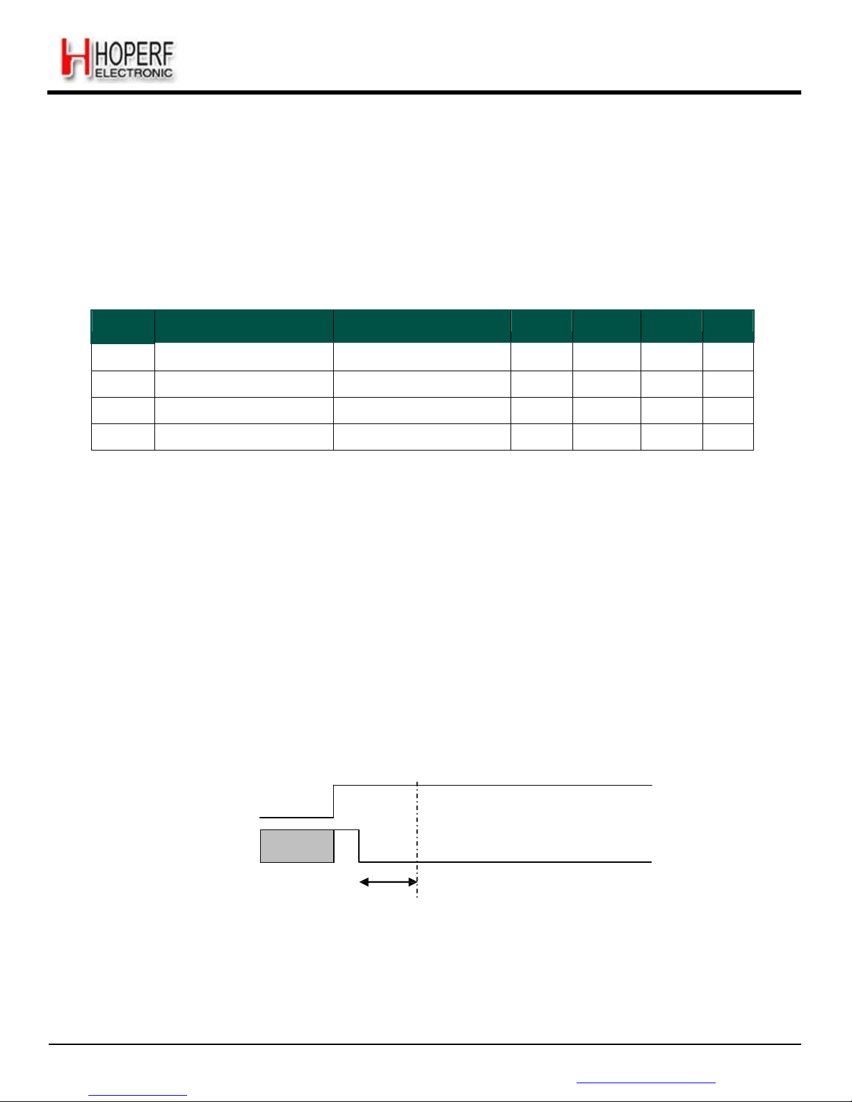
Page 66
RF65
Tel: +86-755-82973805 Fax: +86-755-82973550 E-mail: [email protected] http://www.hoperf.com
ADVANCED COMMUNICATIONS & SENSING DATASHEET
7. Application Information
7.1. Crystal Resonator Specification
Table 26 shows the crystal resonator specification for the crystal reference oscillator circuit of the RF65. This
specification covers the full range of operation of the RF65 and is employed in the reference design.
Table 26 Crystal Specification
Symbol
Description
Conditions
Min Typ
Max
Unit
FXOSC
XTAL Frequency
26 - 32
MHz
RS
XTAL Serial Resistance
-
30
140
ohms
C0
XTAL Shunt Capacitance
-
2.8
7
pF
CLOAD
External Foot Capacitance
On each pin XTA and XTB
8
16
22
pF
Notes - the initial frequency tolerance, temperature stability and ageing performance should be chosen in accordance
with the target operating temperature range and the receiver bandwidth selected.
- the loading capacitance should be applied externally, and adapted to the actual Cload specification of the XTAL.
- A minimum XTAL frequency of 28 MHz is required to cover the 863-870 MHz band, 29 MHz for the 902-928 MHz
band
7.2. Reset of the Chip
A power-on reset of the RF65 is triggered at power up. Additionally, a manual reset can be issued by controlling pin 6.
7.2.1. POR
If the application requires the disconnection of VDD from the RF65, despite of the extremely low Sleep Mode current, the
user should wait for 10 ms from of the end of the POR cycle before commencing communications over the SPI bus. Pin 6
(Reset) should be left floating during the POR sequence.
VDD
Pin
6
(output)
Undefined
Wait for
10 ms
Chip is ready from
this point on
Figure 34. POR Timing
Diagram
Please note that any CLKOUT activity can also be used to detect that the chip is ready.
Page 67
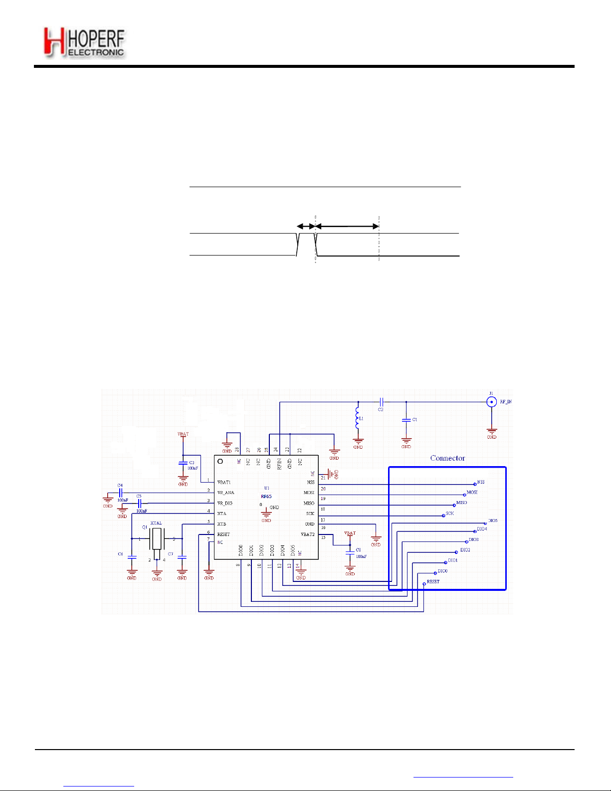
Page 67
RF65
Tel: +86-755-82973805 Fax: +86-755-82973550 E-mail: [email protected] http://www.hoperf.com
ADVANCED COMMUNICATIONS & SENSING DATASHEET
7.2.2. Manual Reset
A manual reset of the RF65 is possible even for applications in which VDD cannot be physically disconnected. Pin 6
should be pulled high for a hundred microseconds, and then released. The user should then wait for 5 ms before using the
chip.
VDD
Pin 6
High-Z
> 100 us
‟‟1‟‟
Wait for
5 ms
High-Z
Chip is ready from
this point on
(input)
Figure 35. Manual Reset Timing
Diagram
Note whilst pin 6 is driven high, an over current consumption of up to ten milliamps can be seen on VDD.
7.3. Reference Design
All schematics shown in this section are full schematics, listing ALL required components, including decoupling capacitors.
Figure 36. Application
Schematic
Note In very cost-sensitive and/or size-constrained applications where it is acceptable to degrade the receiver sensitivity
by approximately 2 dB, L1 and C1 can be omitted.
ADVANCED COMMUNICATIONS & SENSING DATASHEET
Page 68
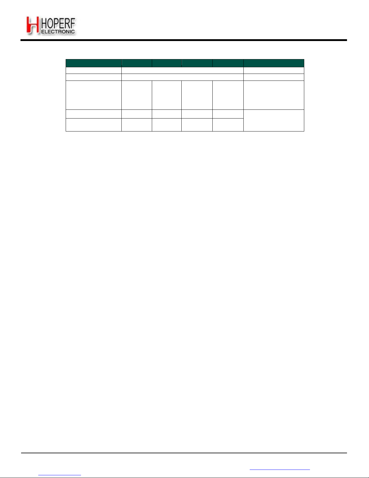
Page 68
RF65
Tel: +86-755-82973805 Fax: +86-755-82973550 E-mail: [email protected] http://www.hoperf.com
Table 32 Receiver BOM
Designator
315 MHz
433 MHz
868 MHz
915 MHz
Type
C3, C4, C5, C8 100
nF
X7R
C6, C7
15
pF
COG
L1
39 nH
33 nH - -
Wirewound
air core or
multilayer
(1)
C1
- - 5.6 pF
5.6 pF
COG
C2
12 pF
12 pF
6.8 nH
5.6 nH
Notes
- (1) Inductor values may change when using multilayer type components
Page 69
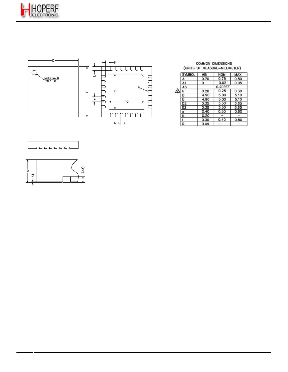
Page 69
RF65
Tel: +86-755-82973805 Fax: +86-755-82973550 E-mail: [email protected] http://www.hoperf.com
8. Packaging Information
8.1. Package Outline Drawing
The RF65 is available in a 28-lead QFN package as show in Figure 37.
Figure 37. Package Outline Drawing
8.2. Thermal Impedance
The thermal impedance of this package is: Theta ja = 23.8° C/W typ., calculated from a package in still air,
on a 4-layer
FR4 PCB, as per the Jedec standard.
Page 70
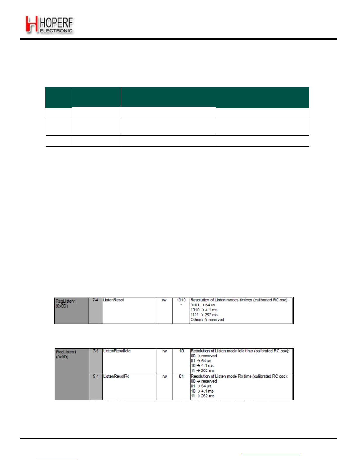
Page 70
RF65
Tel: +86-755-82973805 Fax: +86-755-82973550 E-mail: [email protected] http://www.hoperf.com
9. Chip Revisions
Three distinct chip populations exist and can be identified as follows:
Table 27 Chip Identification
Chip
Version
Register Value
@ address 0x10
Lot Codes
(see Figure 3)
Comment
V2a
0x21
W0K976.00
Limited supply
V2b
0x22
W6A114.0A ¦ W0N382.00
W0N386.00 ¦ W0P051.00
Limited supply
V2c
0x23
W0S934.01 and all others
Running production
This document describes the behavior and characteristics of the RF65 V2c. Minor differences can be observed between
the three versions, and they are listed in the following sub sections.
9.1. RC Oscillator Calibration
On the RF65 V2a, RC calibration at power-up needs to be performed according to the following routine:
/////// RC CALIBRATION (Once at POR) ///////
SetRFMode(RF_STANDBY);
WriteRegister(0x57, 0x80);
WriteRegister(REG_OSC1, ReadRegister(REG_OSC1) | 0x80);
while (ReadRegister(REG_OSC1) & 0x40 == 0x00);
WriteRegister(REG_OSC1, ReadRegister(REG_OSC1) | 0x80);
while (ReadRegister(REG_OSC1) & 0x40 == 0x00);
WriteRegister(0x57, 0x00);
////////////////////////////////////////////
This is not required in the version V2b any more, where the calibration is fully automatic.
9.2. Listen Mode
9.2.1. Resolutions
On the RF65 V2a, the Listen mode resolutions were identical for the Idle phase and the Rx phase. They are now
independently configurable, adding flexibility in the setup of the Listen mode.
Figure 38. Listen Mode Resolutions, V2a
Figure 39. Listen Mode Resolution, V2b
Page 71
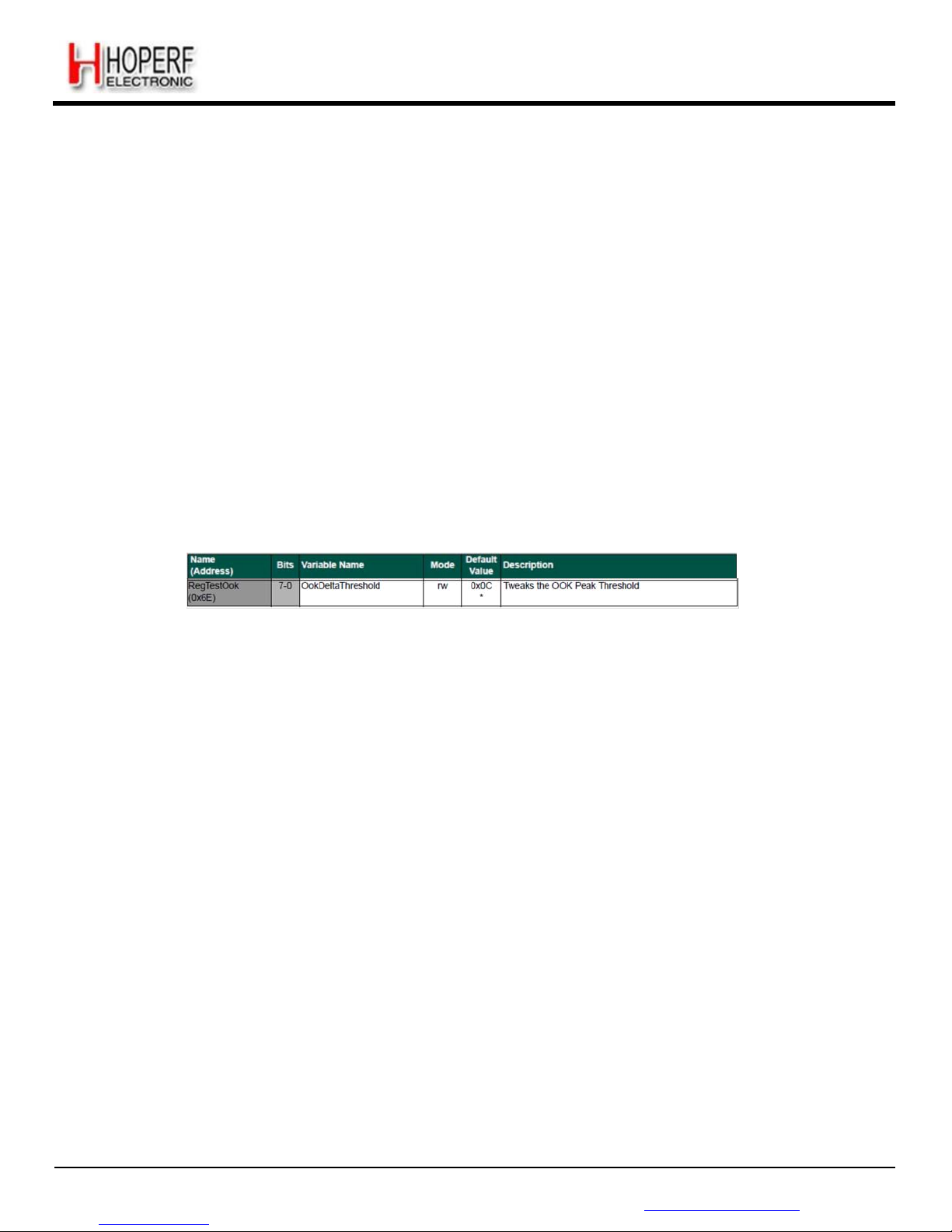
Page 71
RF65
Tel: +86-755-82973805 Fax: +86-755-82973550 E-mail: [email protected] http://www.hoperf.com
ADVANCED COMMUNICATIONS & SENSING DATASHEET
9.2.2. Exiting Listen Mode
In the RF65 V2a, the following procedure was requested to exit Listen mode:
For all three ListenEnd settings (i.e. even for 00 and 01) disabling Listen mode can be done
anytime by writing all together in a single SPI write command (same register) :
Š ListenOn to 0
Š ListenAbort to 1
Mode to the wanted operation mode
Figure 40. Exiting Listen Mode in RF65
V2a
Listen mode can simply be exited on the RF65 V2b by resetting bit ListenOn to 0 in RegListen.
9.3. OOK Floor Threshold Default Setting
The following default value modification was required on the V2a silicon:
Figure 41. RegTestOok
Description
It is not required to modify this register any more on the RF65 V2b.
9.4. AFC Control
The following differences are observed between silicon revisions V2a and V2b:
9.4.1. AfcAutoClearOn
On the RF65 V2a, it is required to manually clear AfcValue in RegAfcFei, when the device is in Rx mode.
AfcAutoClear function is fully functional on the silicon version V2b.
9.4.2. AfcLowBetaOn and LowBetaAfcOffset
Those two bits enable a functionality that was not available on the silicon version V2a.
9.5. ContinuousDagc
This register enables a functionnality that is only available in the silicon version V2c.
Page 72
Page 72
RF65
Tel: +86-755-82973805 Fax: +86-755-82973550 E-mail: [email protected] http://www.hoperf.com
ADVANCED COMMUNICATIONS & SENSING DATASHEET
HOPE MICROELECTRONICS CO.,LTD
Add: 2/F, Building 3, Pingshan Private
Enterprise Science and Technology
Park, Lishan Road, XiLi Town, Nanshan
District, Shenzhen, Guangdong, China
Tel: 86-755-82973805
Fax: 86-755-82973550
Email: [email protected]
Website: http://www.hoperf.com
http://www.hoperf.cn
This document may contain preliminary information and is subject to
change by Hope Microelectronics without notice. Hope Microelectronics
assumes no responsibility or liability for any use of the information
contained herein. Nothing in this document shall operate as an express or
implied license or indemnity under the intellectual property rights of Hope
Microelectronics or third parties. The products described in this document
are not intended for use in implantation or other direct life support
applications where malfunction may result in the direct physical harm or
injury to persons. NO WARRANTIES OF ANY KIND, INCLUDING, BUT
NOT LIMITED TO, THE IMPLIED WARRANTIES OF MECHANTABILITY
OR FITNESS FOR A ARTICULAR PURPOSE, ARE OFFERED IN THIS
DOCUMENT.
©2006, HOPE MICROELECTRONICS CO.,LTD. All rights reserved.
 Loading...