

Page 1

CANISTERS
39000067 T8250 011
Service Manual
Page 2
Page 3
Page 4
DISCOVERY Suction Cleaners
Page 5

Copyright 2004 Gias S.r.L.
Ricambio
Part No.
Piece
E-Teil
Pieza
Inizio
Beginning
Debut
Begin
Inicio
Fine
Ending
Fin
End
Fin
Ref.
Descrizione - Description - Beschreibung - Descripcion
Mod: 39000067 T8250 011 0312 (17/03/2003)
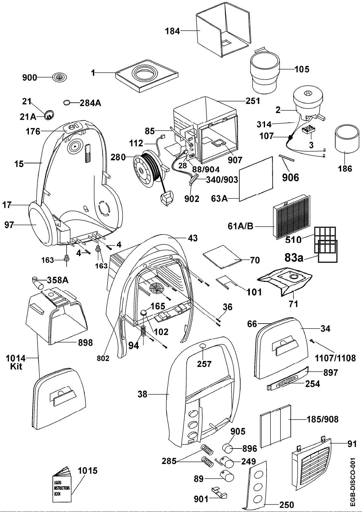
1
2
3
4
15
17
21
21a
28
34
36
38
Motor mount - fan end
Motor assembly
Motor mount - commutator end
Screw
Chassis
Rear wheel
Front wheel
Castor support
Washer
Bag door
Screw
Top cover
03870725
04315013
03870724
09184227
03725161
03850308
09082132
09054941
09184235
04225282
09161506
03725162
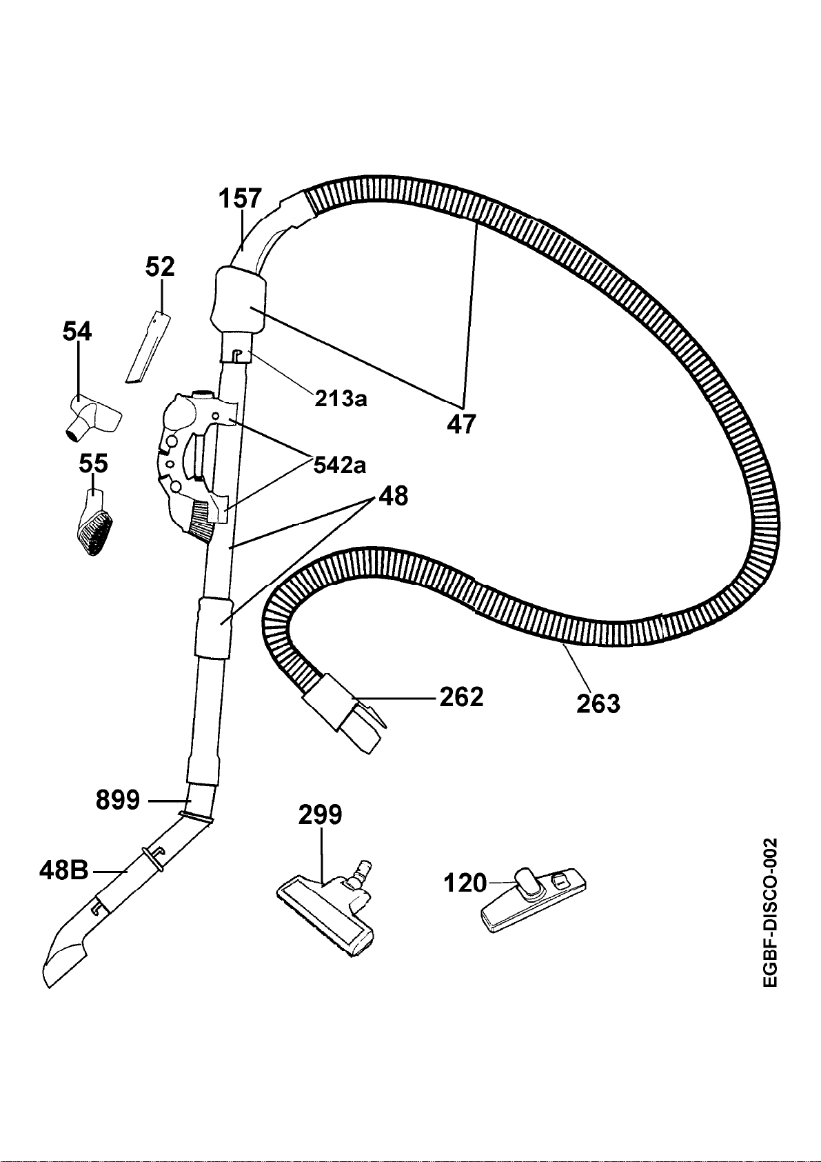
43
48
52
54
55
61d
63a
66
70
85
89
91
94
97
102
Bag housing
Extension tube
Crevice tool
Furniture nozzle
Dusting brush
Hepa filter
Seal (Exhaust)
Bag door seal
Pre-motor filter
Pressure switch tube
On/Off button / switch button small
Filter cover
Spring
Wheel cover
Seal
04225242
04345054
09184128
09184177
09184169
09205469
03875003
03870726
09183930
06605002
03991025
03875008
03831181
03855006
03870606
105
112
120
157
Motor support
Cord reel harness
Floor nozzle
Handle tube upper (curved hose end)
03710088
04625000
09184201
03940692
Page 6

Copyright 2004 Gias S.r.L.
Ricambio
Part No.
Piece
E-Teil
Pieza
Inizio
Beginning
Debut
Begin
Inicio
Fine
Ending
Fin
End
Fin
Ref.
Descrizione - Description - Beschreibung - Descripcion
Mod: 39000067 T8250 011 0312 (17/03/2003)
163
165
176
184
185
186
213a
249
250
251
257
262
Plug
Valve
Inlet housing
Noise reducer
Baffle plate
Noise reducer
Latch ring
Cord reel pedal
Control panel
Motor housing
Roundel (Hoover emblem)
Adapt swivel connector (hose end)
03790653
04350201
03235001
03945000
03945001
03945002
03240093
03991023
03995001
03940688
05160310
03860569
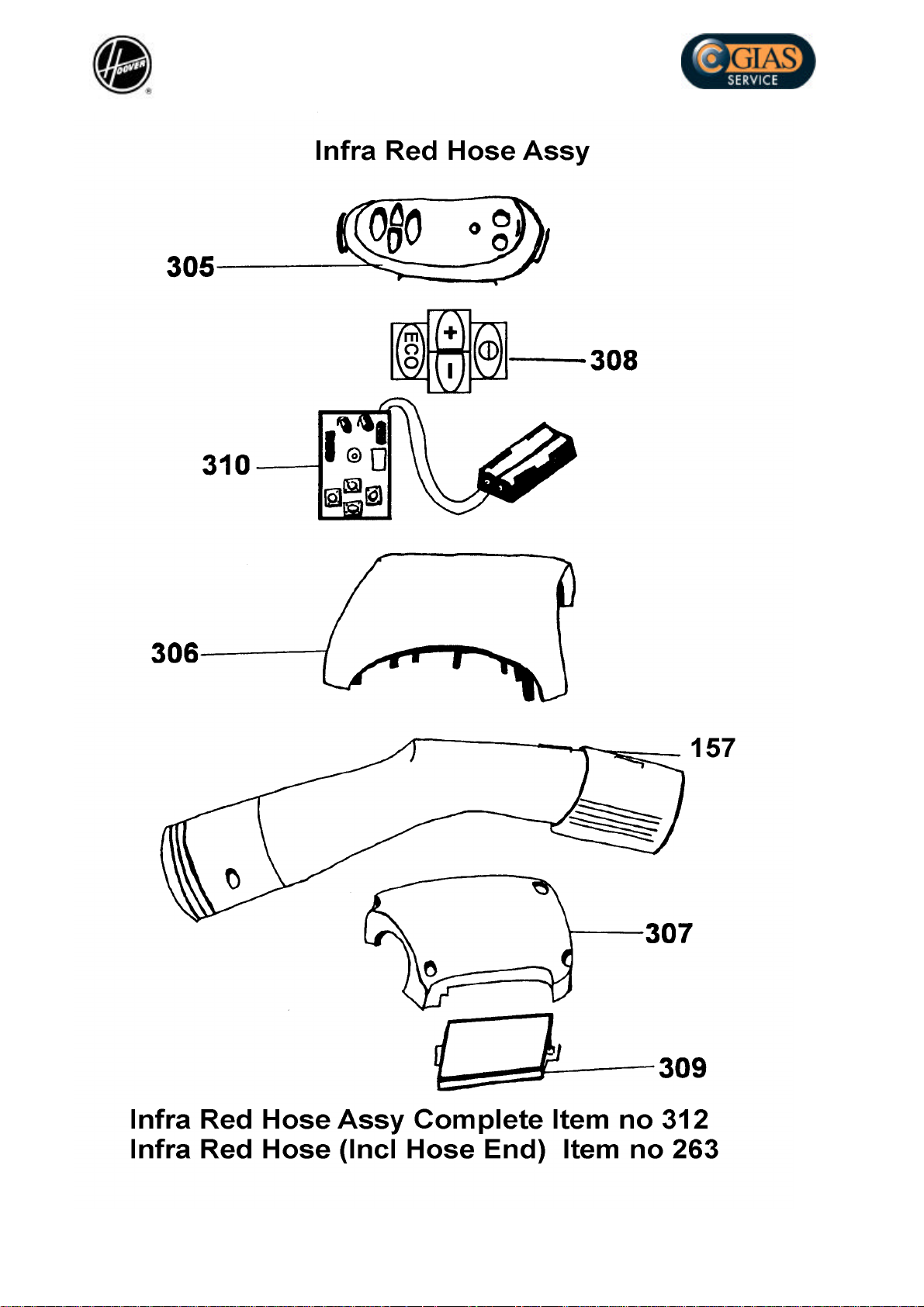
263
280
284a
285
299
305
306
307
308
309
310
312
314
358a
542a
Flexible hose without edges
Cord reel complete
Swivel hose connector seal
Button spring
Turbo nozzle
Infra red switch panel
Infra red housing
Infra red cover
Switch activator printed
Battery cover
Handset module infra red
Infra red remote control hose complete
Motor harness
Inlet duct
Tool holders kit
09184979
04685008
09055054
03835002
04845030
03795002
03725008
03725009
03845000
03795000
04785004
04345055
04635000
03645001
09184524
802
898
900
901
Seal
Porous container(Eco-Box)
Inlet housing switch
Park switch actuator
03870750
06015624
03870722
03995000
Page 7

Copyright 2004 Gias S.r.L.
Ricambio
Part No.
Piece
E-Teil
Pieza
Inizio
Beginning
Debut
Begin
Inicio
Fine
Ending
Fin
End
Fin
Ref.
Descrizione - Description - Beschreibung - Descripcion
Mod: 39000067 T8250 011 0312 (17/03/2003)
902
903
904
905
906
907
1107
1108
LED support lens
I.R.indicator PCB assy
LED control panel
Infra red lens
Filter check tube
Support shroud
Latch LH
Latch RH
03995007
04685031
03995004
03995006
06605003
03870723
03615007
03615005
Page 8

Page 9

DISCOVERY Suction Cleaners
Discovery Fitting Notes
Before carrying out any repairs on the appliance remove the following:
Dust Container
Press the dust container handle .
Rotate the handle clockwise and lift the dust container assembly out of the bag
housing.
Exhaust Filter
Lift up the rear vented cover and take out the exhaust filter assembly.
Top Cover/ Pedal /Lens Removal
Detach the dust container and exhaust filter as previously described.
The six screws securing the top cover,two at the rear and four at each corner of the
dust container compartment are now accessible.
Remove the six screws.
The top cover with the pedals and the bag full indicator lens can now be lifted away.
To change the pedals or bag full indicator lens, undo the two screws on the underside
of the top cover allowing the main control panel to be lifted off .
The pedals and lens can now be pushed out of the assembly as required.
Module
Remove the top cover.
The module is fixed to the motor housing by one screw situated 55mm from the rear of
the module.
Removing the screw allows the module to be lifted off.
When removing the module take care to note the position of the connector plugs and
amp tags fitted on it.
Re-fit in reverse order.
When replacing the module make sure that the plastic shoulder washer is fitted under
the head of the fitting screw.
CAUTION! If the two wire plug from the cord reel is inadvertently fitted in between the
two amp tags, the cleaner will run constantly when connected to the mains without the
need to actuate the on –off switch:-
DO NOT under any circumstances connect the lead in this position.
ON some models this position on the board may be used for the P T O Socket.
Motor and Cord Reel Removal
Remove the top cover.
Remove the four recessed screws around the dust container area.
Detach the cord reel two pin connector from the module.
The bag housing with the motor housing assembly and module attached to it can now
be taken out of the appliance.
The module can be serviced as before.
To Remove The Motor:Detach the remaining connectors from the module and separate the motor housing
from the bag housing.
Page 10

DISCOVERY Suction Cleaners
Pull off the large square motor mount/cover from the front of the motor housing.
Lift the plastic motor shroud containing the motor, out of the housing
Motor and Cord Reel Continued:-
The motor, including the cylindrical foam baffle can now be removed from the shroud
for servicing or replacement.
Make sure that the foam baffle is re - fitted to the motor before replacing the motor.
When replacing the motor into the shroud make sure that the rear motor mount is
seated correctly in the base of the shroud without trapping the leads of the motor
harness.
Ensure that the motor leads are positioned on the side of the housing nearest to the
module and tucked into the elongated slot on the bag housing when refitting the
motor.
Cord Reel
Lift the bag housing with the motor assembly attached out of the lower body.
The cord reel will be left in position seated on the base.
Takeout the cord reel for servicing.
When fitting a new mains lead to the cord reel make sure, before the cable is fitted,
that the spring is fully unwound and is tensioned for 2 FULL TURNS MAXIMUM
when the cable is replaced.
Replace the cord reel in the cleaner.
Ensure that the cord reel harness is positioned against the side of the appliance.
Electrical Checks
Check condition of plug--------- if the pins are burnt or body cracked take
appropriate action.
Check condition of the mains lead ---------------if chipped or burnt, take
appropriate action.
Insulation test
Remove the Dust container assy.
Remove the pre - motor filter.
Use a Metrohm.
Bond the Live and Neutral pins with one of the meter clips and connect the other
meter clip to a terminal screwdriver.
Insert the screwdriver through the grill onto the fan casing.
Select- The MEGOHMS SCALE =MINIMUM READING 1 MEGOHM
Page 11

Customer Service
Ufficio Tecnico
Gias International
Aspirapolvere serie: DISCOVERY
Istruzioni per lo smontaggio dei componenti.
Prima di procedere a qualunque riparazione, rimuovere i seguenti componenti:
Contenitore della polvere.
Premere la maniglia di apertura del contenitore della polvere.
Ruotare la maniglia in senso orario. Il coperchio si aggancia al contenitore della polvere e si
sgancia dall'apparecchio. Sollevare l'assieme coperchio/contenitore della polvere fuori dal
proprio alloggiamento (alloggiamento che in altre versioni di futura produzione potrà
contenere un tradizionale sacchetto di carta).
Filtro di scarico.
Sollevare il coperchio posteriore forato ed estrarre l'assieme filtro di scarico.
Smontaggio e sostituzione dei principali componenti:
Copertura superiore / Pedale / Indicatore contenitore polvere pieno:
Smontare il contenitore della polvere ed il filtro di scarico, come descritto in precedenza.
Sono ora accessibili le sei viti che fissano la copertura superiore, due nella parte posteriore
ed una in ognuno dei quattro angoli del contenitore della polvere.
Rimuovere le sei viti.
Ora possono essere rimossi la copertura superiore completa di pedali e di indicatore di
contenitore pieno.
Se necessario, i pedali e l'indicatore possono essere estratti dall'assieme che li supporta.
Modulo elettronico di comando:
Rimuovere la copertura superiore.
Il modulo elettronico è fissato al vano motore tramite una sola vite, situata a 55 mm dalla
parte posteriore del modulo stesso.
Rimuovendo la vite di fissaggio, è possibile estrarre il modulo dal proprio alloggiamento.
Mentre smontate il modulo dall'aspirapolvere, prendete nota della posizione originale dei vari
faston e connettori ad esso collegati.
Montate il nuovo modulo elettronico di comando, operando in senso inverso a quanto
indicato in precedenza.
Nel fissare in posizione il nuovo modulo, ricordarsi di calzare sulla vite di fissaggio del
modulo stesso la rondella isolante in plastica presente in origine.
2000
1
Page 12

ATTENZIONE! Sul modulo elettronico (vedi schema elettrico) sono presenti tra i contatti di
alimentazione del motore due contatti normalmente liberi. Se, per errore, a questi contatti
liberi dovesse essere collegato il cavo di alimentazione proveniente dall'avvolgicavo,
l'aspirapolvere funzionerebbe in modo continuo non appena inserita la spina nella presa,
trovandosi escluso dal circuito l'interruttore principale di acceso/spento.
Per nessun motivo il cavo di alimentazione proveniente dall'avvolgicavo deve essere
collegato a questi contatti normalmente liberi.
Su alcune versioni, a questi contatti è collegato il termostato di sicurezza denominato
PTO.
Smontaggio del motore:
Rimuovere la copertura superiore.
Rimuovere le quattro viti incassate agli angoli del contenitore della polvere.
Disconnettere dal modulo elettronico i due contatti di alimentazione del cavo.
Ora si può rimuovere l'assieme del contenitore polvere, completo di modulo elettronico.
Se necessario, il modulo può essere sostituito operando come descritto in precedenza.
Per smontare il motore, staccate dal modulo elettronico i relativi connettori e separate
l'alloggiamento del motore dall'alloggiamento del contenitore polvere.
Estrarre la copertura/supporto in plastica del motore dal lato anteriore dell'alloggiamento del
motore stesso e rimuoverla dall'apparecchio.
Il motore può ora essere estratto dalla propria copertura/supporto per l'eventuale revisione
e/o sostituzione.
Prima disinserire di nuovo il motore all'interno della propria copertura/supporto, assicurarsi di
aver correttamente posizionato sul motore stesso la protezione insonorizzante in gommaspugna.
All'atto dell'inserimento del motore all'interno della propria copertura/supporto, assicurarsi
che la staffa posteriore del motore vada ad alloggiarsi correttamente nella propria sede alla
base della copertura/supporto, senza schiacciare alcuno dei fili del cablaggio.
Assicurarsi anche di avere correttamente posizionato i fili di alimentazione del motore sul lato
del contenitore che corrisponde al modulo elettronico. Successivamente, gli stessi fili devono
essere fatti passare attraverso l'apposita feritoia a sagoma allungata, presente
sull'alloggiamento del contenitore polvere.
Smontaggio della bobina avvolgicavo:
Sollevare l'assieme contenitore polvere/sacchetto, con l'assieme motore fissato nella parte
bassa. La bobina avvolgicavo rimane alloggiata nella propria sede, sulla carcassa
dell'apparecchio. Rimuovere la bobina avvolgicavo dalla propria sede, per la revisione o
l'eventuale sostituzione.
Nel caso di sostituzione del cavo alimentazione sulla bobina avvolgicavo, svolgere
completamente la molla della stessa, prima di montare il nuovo cavo e riavvolgerla,
tensionandola con un MASSIMO DI 2 ROTAZIONI COMPLETE, all'atto del montaggio
del nuovo cavo. Riposizionare la bobina nel proprio alloggiamento, curando in modo
particolare il corretto e sicuro posizionamento del relativo cablaggio.
2
2000
 Loading...