

Page 1
INSTALLATIONKIT
Installation and Servicing Instructions
Espa_ol- pdginaE1
®
www.h00ver.c0m
IMPORTANT:READCAREFULLYBEFOREASSEMBLYAND USE.
Questions or concerns? For assistance, please call Customer Service at
1-800-944-9200 Mon-Fri 8am-7pm EST before returning this product to the store.
THIS PRODUCTIS INTENDEDFORHOUSEHOLDUSEONLY.
IF USEDCOMMERCIALLYWARRANTYIS VOID.
@2010 Techtronic Floor Care Technology Limited. All rights reserved. #961109003 ID100476-R0
Page 2
Thankyou for choosing a HOOVER_ product.
Items Needed For Installation .......................................................................... 3
Carton Contents ................................................................................................ 4
Installation Kit ................................................................................................. 4
Introduction ........................................................................................................ 5
Planning The Built-In System .......................................................................... 5
Grounding Method .......................................................................................... 5
Determine Location for Inlet Valves ................................................................ 6
Planning Tubing System ................................................................................. 6
Installation ......................................................................................................... 7
Installing Wall Inlet Valves .............................................................................. 7
Installing Floor Inlet Valves ............................................................................. 9
Installing Tube System .................................................................................... 9
New House Construction ................................................................................ 10
Mounting Power Unit ...................................................................................... 10
Installing Optional Exhaust System ................................................................ 11
Final Systems Check ...................................................................................... 11
Wiring Instructions for Electrified Central Vacuum inlet Valve ........................ 11
Service ................................................................................................................ 12
If you need assistance:
Visit our website at hoover.com and follow the service center Iocator link to find the Hoover _ authorized
dealer nearest you, Or call 1-800-944-9200 to speak with a customer service representative; Mon-Fri
8am-7pm EST.
Please do not return this product to the store.
Page 3
HOOVER®CENTRALVACUUMSYSTEMS
REVIEWTHIS MANUALBEFOREINSTALLINGCLEANINGSYSTEM
The HOOVER® Central Vacuum System is sold as a system or as three
separate kits:
1. A Power Canister Unit, which will be permanently mounted.
2. An installation kit of tubing and wiring to connectthe power unit to the wall
inlets.
3. An accessorykit consisting of hose, nozzle, and tools.
ITEMS NEEDEDFOR INSTALLATION:
1/4" to 1/2" electric drill*
Steel tape measure
Wire cutters
Hammer
Masonry drill
Pocketknife
2-1/2" hole saw or cutter
Key hole saw
Phillips screwdriver
Slotted screwdriver
Hacksaw
Wood chisel
Coat hanger (metal)
2" hose clamps
(2) 1-1/2" x 1/4" lag bolts
Electrical tape
Right angle drill*
Drill extensions (5 1/2". 12". 18")*
*These tools can be rented
Page 4
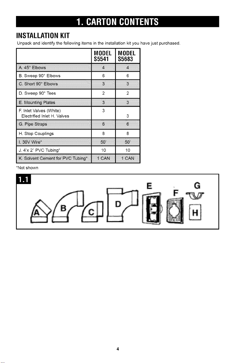
INSTALLATIONKIT
Unpack and identify the following items in the installation kit you have just purchased.
MODEL MODEL
$5541 $5683
B. Sweep 90° Elbows 6 6
D. Sweep 90 ° Tees 2 2
F. Inlet Valves (White) 3
Electrified inlet H. Valves 3
H. Stop Couplings 8 8
J. 4'x 2" PVC Tubing* 10 10
*Not shown
Page 5
Before attempting to install your HOOVER <_Central Vacuum System, read these instructions
thoroughly. Understanding the built-in system will simplify the installation.
A preliminary survey of the home will help determine the best location for the Power Canister Unit which
determines the best path for the tubing system. A thorough study will reveal the location of heating
ducts, plumbing lines, electrical wiring and other obstructions which might hinder installation. Plan
ahead!
PLANNING THE BUILT-IN SYSTEM
DetermineLocationfor PowerUnit
The power unit can be mounted in the basement,
utility room, garage or any other remote area,
except where exposed to weather. The unit
requires ventilation. DO NOT install in a heat
producing or confined area such as the attic,
furnace room ect. If desired, the power unit can
be exhausted to the outside.
AkCAUTION
DO NOT install unit in any area where dust
could harm sensitive equipment, delicate
furnishings or other items.
The top of the unit should be no less than 12"
from the ceiling and no less than 12" from any
side wall (excluding the wall on which model is
mounted). For ease of removing the dust
container, the bottom of the unit should be at least
18" above the floor.
Central Vacuum Power Units require a separate/
dedicated, 120 volt, 60 Hz., 15 Amp, 3 wire
grounded power circuit, protected by a 120 Volt,
60 Hz., AC, 15 Amp time delay fuse or circuit
breaker and a 120 Volt, 60 Hz., 15Amp grounded
receptacle.
Ifa 120 Volt, 60 Hz., 15Amp grounded receptacle
is not available, have a qualified electrician install
one for you. The receptacle should be no more
than 5 feet from the Power Unit.
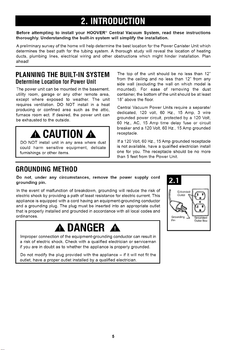
GROUNDING METHOD
Do not, under any circumstances, remove the power supply cord
grounding pin.
In the event of malfunction of breakdown, grounding will reduce the risk of
electric shock by providing a path of least resistance for electric current. This
appliance is equipped with a cord having an equipment-grounding conductor
and a grounding plug. The plug must be inserted into an appropriate outlet
that is properly installed and grounded in accordance with all local codes and
ordinances.
DANGER
Improper connection of the equipment-grounding conductor can result in
a risk of electric shock. Check with a qualified electrician or serviceman
if you are in doubt as to whether the appliance is properly grounded.
Do not modify the plug provided with the appliance - if it will not fit the
outlet, have a proper outlet installed by a qualified electrician.
Page 6
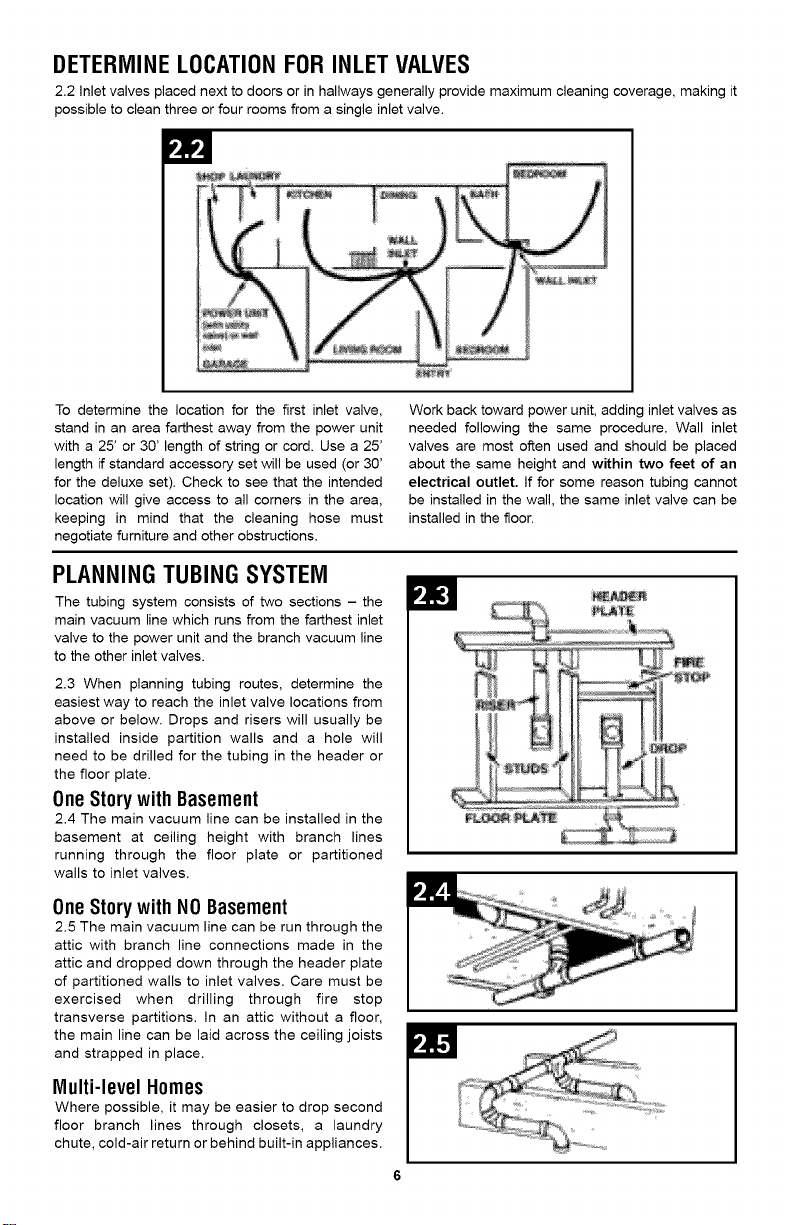
DETERMINE LOCATION FOR INLET VALVES
2.2 inlet valves placed next to doors or in hallways generally provide maximum cleaning coverage, making it
possible to clean three or four rooms from a single inlet valve.
To determine the location for the first inlet valve,
stand in an area farthest away from the power unit
with a 25' or 30' length of string or cord. Use a 25'
length if standard accessory set will be used (or 30'
for the deluxe set). Check to see that the intended
location will give access to all corners in the area,
keeping in mind that the cleaning hose must
negotiate furniture and other obstructions.
PLANNING TUBING SYSTEM
The tubing system consists of two sections - the
main vacuum line which runs from the farthest inlet
valve to the power unit and the branch vacuum line
to the other inlet valves.
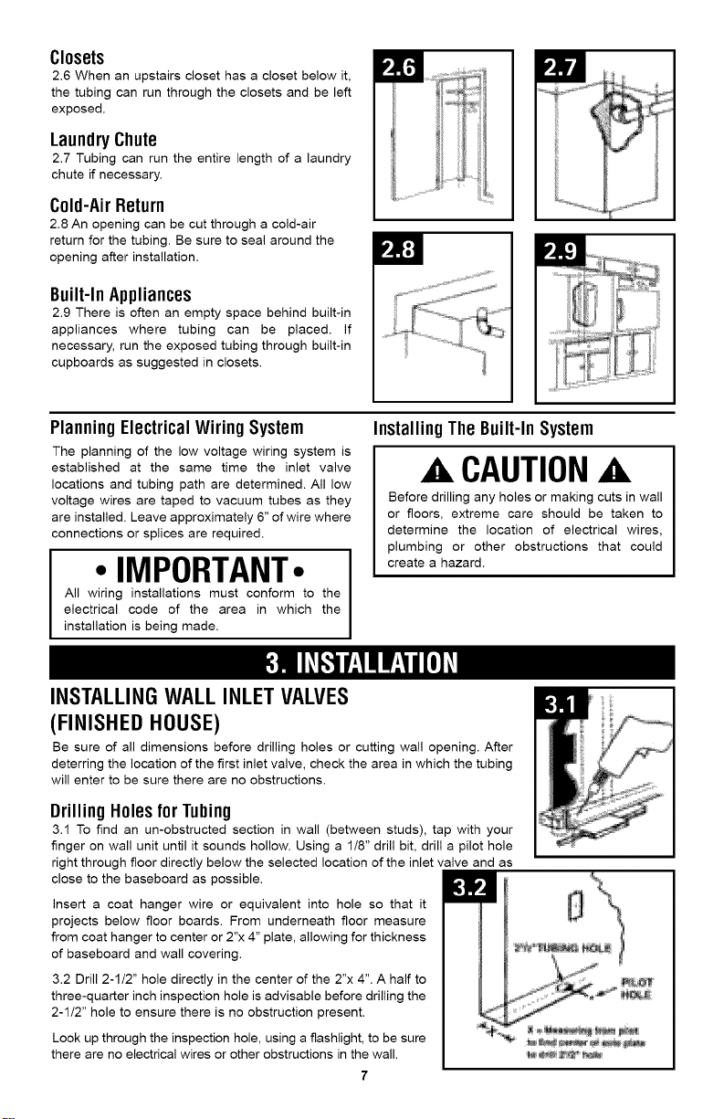
2.3 When planning tubing routes, determine the
easiest way to reach the inlet valve locations from
above or below. Drops and risers will usually be
installed inside partition walls and a hole will
need to be drilled for the tubing in the header or
the floor plate.
OneStorywith Basement
2.4 Time main vacuum line can be installed in the
basement at ceiling height with branch lines
running through the floor plate or partitioned
walls to inlet valves.
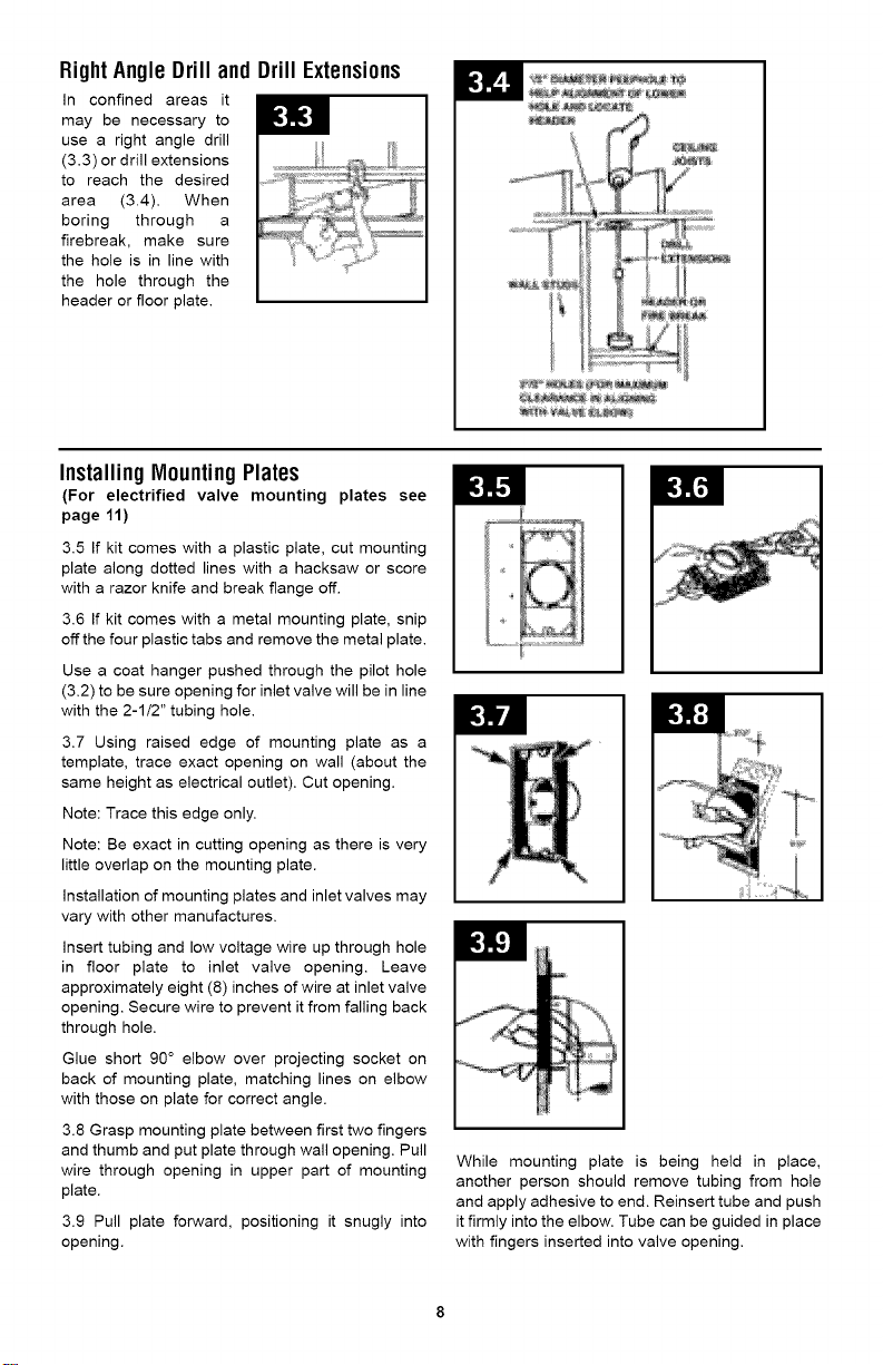
OneStorywith NOBasement
2.5 The main vacuum line can be run through time
attic with branch line connections made in the
attic and dropped down through the header plate
of partitioned walls to inlet valves. Care must be
exercised when drilling through fire stop
transverse partitions. In an attic without a floor,
the main line can be laid across the ceiling joists
and strapped in place.
Multi-level Homes
Where possible, it may be easier to drop second
floor branch lines through closets, a laundry
chute, cold-air return or behind built-in appliances.
Work back toward power unit, adding inlet valves as
needed following the same procedure. Wall inlet
valves are most often used and should be placed
about the same height and within two feet of an
electrical outlet. If for some reason tubing cannot
be installed in the wall, the same inlet valve can be
installed in the floor.
Page 7
Closets
2.6 When an upstairs closet has a closet below it,
the tubing can run through the closets and be left
exposed.
LaundryChute
2.7 Tubing can run the entire length of a laundry
chute if necessary.
Cold-AirReturn
2.8 An opening can be cut through a cold-air
return for the tubing. Be sure to seal around the
opening after installation.
Built-InAppliances
2.9 There is often an empty space behind built-in
appliances where tubing can be placed. If
necessary, run the exposed tubing through built-in
cupboards as suggested in closets.
Planning ElectricalWiring System
The planning of the low voltage wiring system is
established at the same time the inlet valve
locations and tubing path are determined. All low
voltage wires are taped to vacuum tubes as they
are installed. Leave approximately 6" of wire where
connections or splices are required.
• IMPORTANT•
All wiring installations must conform to the
electrical code of the area in which the
installation is being made.
InstallingThe Built-InSystem
AkCAUTIONA
Before drilling any holes or making cuts in wall
or floors, extreme care should be taken to
determine the location of electrical wires,
plumbing or other obstructions that could
create a hazard.
INSTALLING WALL INLET VALVES
(FINISHEDHOUSE)
Be sure of all dimensions before drilling holes or cutting wall opening. After
deterring the location of the first inlet valve, check the area in which the tubing
will enter to be sure there are no obstructions.
Drilling HolesforTubing
3.1 To find an un-obstructed section in wall (between studs), tap with your
finger on wall unit until it sounds hollow. Using a 1/8" drill bit, drill a pilot hole
right through floor directly below the selected location of the inlet valve and as
close to the baseboard as possible.
Insert a coat hanger wire or equivalent into hole so that it
projects below floor boards. From underneath floor measure
from coat hanger to center or 2"x 4" plate, allowing for thickness
of baseboard and wall covering.
3.2 Drill 2-1/2" hole directly in the center of the 2"x 4". A half to
three-quarter inch inspection hole is advisable before drilling the
2-1/2" hole to ensure there is no obstruction present.
Look up through the inspection hole, using a flashlight, to be sure
there are no electrical wires or other obstructions in the wall.
)ItI ,1
Page 8
RightAngle Drill and Drill Extensions
In confined areas it
may be necessary to
use a right angle drill
(3.3) or drill extensions
to reach the desired
area (3.4). When
boring through a
firebreak, make sure
the hole is in line with
the hole through the
header or floor plate.
InstallingMountingPlates
(For electrified valve mounting plates see
page 11)
3.5 If kit comes with a plastic plate, cut mounting
plate along dotted lines with a hacksaw or score
with a razor knife and break flange off.
3.6 If kit comes with a metal mounting plate, snip
off the four plastic tabs and remove the metal plate.
Use a coat hanger pushed through the pilot hole
(3.2) to be sure opening for inlet valve will be in line
with the 2-1/2" tubing hole.
3.7 Using raised edge of mounting plate as a
template, trace exact opening on wall (about the
same height as electrical outlet). Cut opening.
Note: Trace this edge only.
Note: Be exact in cutting opening as there is very
little overlap on the mounting plate.
installation of mounting plates and inlet valves may
vary with other manufactures.
insert tubing and low voltage wire up through hole
in floor plate to inlet valve opening. Leave
approximately eight (8) inches of wire at inlet valve
opening. Secure wire to prevent it from falling back
through hole.
Glue short 90 ° elbow over projecting socket on
back of mounting plate, matching lines on elbow
with those on plate for correct angle.
3.8 Grasp mounting plate between first two fingers
and thumb and put plate through wall opening. Pull
wire through opening in upper part of mounting
plate.
3.9 Pull plate forward, positioning it snugly into
opening.
While mounting plate is being held in place,
another person should remove tubing from hole
and apply adhesive to end. Reinsert tube and push
it firmly into the elbow. Tube can be guided in place
with fingers inserted into valve opening.
Page 9
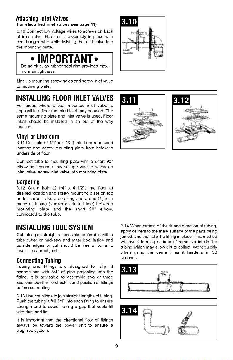
AttachingInlet Valves
(for electrified inlet valves see page 11)
3.10 Connect low voltage wires to screws on back
of inlet valve. Hold entire assembly in place with
coat hanger wire while twisting the inlet valve into
the mounting plate.
Do no glue, as rubber seal ring provides maxi-
• IMPORTANT- I
mum air tightness.
Line up mounting screw holes and screw inlet valve
to mounting plate.
INSTALLING FLOORINLET VALVES
For areas where a wail mounted inlet valve is
impossible a floor mounted inlet may be used. The
same mounting plate and inlet valve is used. Floor
inlets should be installed in an out of the way
location,
Vinylor Linoleum
3.11 Cut hole (2-1/4" x 4-1/2") into floor at desired
location and screw mounting plate from below to
underside of floor.
Connect tube to mounting plate with a short 90 °
elbow and connect low voltage wire to screw on
inlet valve; screw inlet valve into mounting plate.
Carpeting
3.12 Cut a hole (2-1/4" x 4-1/2") into floor at
desired location and screw mounting plate on top
under carpet. Use a coupling and a one (1) inch
piece of tubing (shown as dotted line) between
mounting plate and the short 90 ° elbow,
connected to the tube.
INSTALLINGTUBESYSTEM
Cut tubing as straight as possible, preferable with a
tube cutter or hacksaw and miter box. Inside and
outside edges or cut should be free of burrs to
insure leak proof joints.
ConnectingTubing
Tubing and fittings are designed for slip fit
connections with 3/4" of pipe projecting into the
fitting. It is advisable to assemble two or three
sections together to check fit and position of fittings
before cementing.
3.13 Use couplings to join straight lengths of tubing.
Push the tubing a full 3/4" into each fitting to ensure
strength and to avoid having a gap that could fill
with dust and lint.
It is important that the directional flow of fittings
always be toward the power unit to ensure a
clog-free system.
fin
3.14 When certain of the fit and direction of tubing,
apply cement to the male surface of the parts being
joined, and then slip the fitting in place. This method
will avoid forming a ridge of adhesive inside the
tubing which may allow dirt to collect. Work quickly
when using the cement, as it hardens in 30
seconds.
Page 10
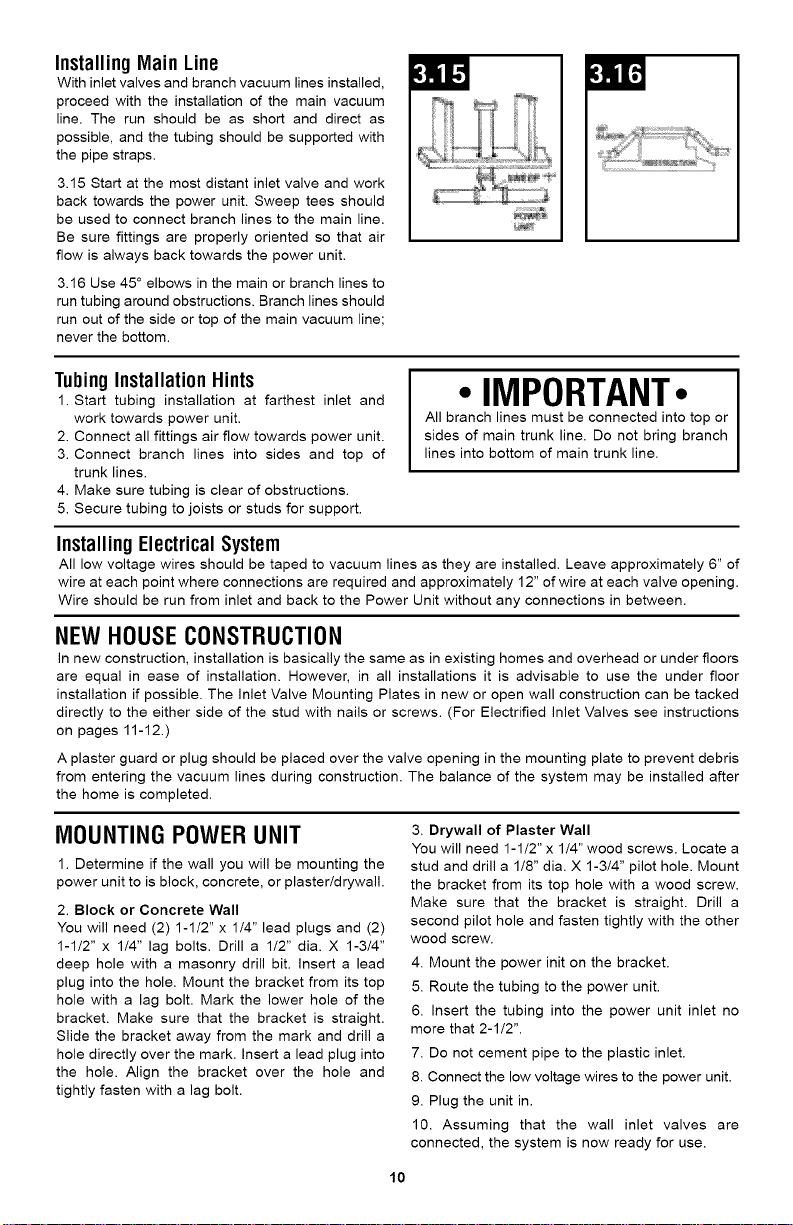
InstallingMain Line
With inlet valves and branch vacuum lines installed,
proceed with the installation of the main vacuum
line. The run should be as short and direct as
possible, and the tubing should be supported with
the pipe straps.
3.15 Start at the most distant inlet valve and work
back towards the power unit. Sweep tees should
be used to connect branch lines to the main line.
Be sure fittings are properly oriented so that air
flow is always back towards the power unit.
3.16 Use 45 ° elbows in the main or branch lines to
run tubing around obstructions. Branch lines should
run out of the side or top of the main vacuum line;
never the bottom.
lcJllJ
TubingInstallationHints
1. Start tubing installation at farthest inlet and
work towards power unit.
2. Connect all fittings air flow towards power unit.
3. Connect branch lines into sides and top of
trunk lines.
4. Make sure tubing is clear of obstructions.
5. Secure tubing to joists or studs for support.
• IMPORTANT.
All branch lines must be connected into top or
sides of main trunk line. Do not bring branch
lines into bottom of main trunk line.
InstallingElectricalSystem
All low voltage wires should be taped to vacuum lines as they are installed. Leave approximately 6" of
wire at each point where connections are required and approximately 12" of wire at each valve opening.
Wire should be run from inlet and back to the Power Unit without any connections in between.
NEW HOUSE CONSTRUCTION
In new construction, installation is basically the same as in existing homes and overhead or under floors
are equal in ease of installation. However, in all installations it is advisable to use the under floor
installation if possible. The inlet Valve Mounting Plates in new or open wall construction can be tacked
directly to the either side of the stud with nails or screws. (For Electrified inlet Valves see instructions
on pages 11-12.)
A plaster guard or plug should be placed over the valve opening in the mounting plate to prevent debris
from entering the vacuum lines during construction. The balance of the system may be installed after
the home is completed.
MOUNTING POWER UNIT
1. Determine if the wall you will be mounting the
power unit to is block, concrete, or plaster/drywall.
2. Block or Concrete Wall
You will need (2) 1-1/2" x 1/4" lead plugs and (2)
1-1/2" x 1/4" lag bolts. Drill a 1/2" dia. X 1-3/4"
deep hole with a masonry drill bit. insert a lead
plug into the hole. Mount the bracket from its top
hole with a lag bolt. Mark the lower hole of the
bracket. Make sure that the bracket is straight.
Slide the bracket away from the mark and drill a
hole directly over the mark. Insert a lead plug into
the hole. Align the bracket over the hole and
tightly fasten with a lag bolt.
3. Drywall of Plaster Wall
You will need 1-1/2" x 1/4" wood screws. Locate a
stud and drill a 1/8" dia. X 1-3/4" pilot hole. Mount
the bracket from its top hole with a wood screw.
Make sure that the bracket is straight. Drill a
second pilot hole and fasten tightly with the other
wood screw.
4. Mount the power init on the bracket.
5. Route the tubing to the power unit.
6. Insert the tubing into the power unit inlet no
more that 2-1/2".
7. Do not cement pipe to the plastic inlet.
8. Connect the low voltage wires to the power unit.
9. Plug the unit in.
10. Assuming that the wall inlet valves are
connected, the system is now ready for use.
10
Page 11
INSTALLING OPTIONAL EXHAUST SYSTEM
The exhaust from the power unit may be vented
to the outside, if desired. Do not vent exhaust
close to a door or window or where it will disturb
neighbors.
The outside vent should go through the wall about
2' above the floor or ground level. A sharp 90 °
elbow should then be attached outside as close to
the wall as possible with 6" of tubing added to
direct exhaust downward.
When power unit is located in a room below
ground level, the exhaust can usually be vented
outside between or at joist level. Measure
carefully the location desired. If the exterior is
brick, carefully chisel away brick and mortar to
create an approximate 2-1/2" diameter hole. Then
drill hole into house, install vent pipe and brick to
seal opening.
FINAL SYSTEMS CHECK
Check each wall inlet to be sure contacts activate power unit when hose is inserted. A short piece of
wire can be used to short contacts in a wall inlet together to activate power unit. Check each wall inlet
and tubing connection for air leaks. Check power unit for leaks around inlet tube and dirt receptacle.
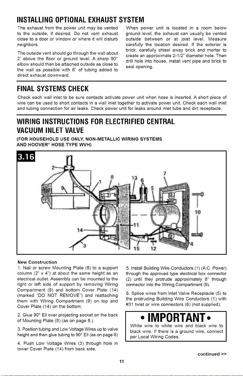
WIRING INSTRUCTIONS FOR ELECTRIFIEDCENTRAL
VACUUM INLET VALVE
(FOR HOUSEHOLD USE ONLY, NON-METALLIC WIRING SYSTEMS
AND HOOVER <_HOSE TYPE WVH)
)=Ill
New Construction
1. Nail or screw Mounting Plate (8) to a support
column (2" x 4") at about the same height as an
electrical outlet. Assembly can be mounted to the
right or left side of support by removing Wiring
Compartment (9) and bottom Cover Plate (14)
(marked "DO NOT REMOVE") and reattaching
them with Wiring Compartment (9) on top and
Cover Plate (14) on the bottom.
2. Glue 90 ° Ell over projecting socket on the back
of Mounting Plate (8) (as on page 8.)
3. Position tubing and Low Voltage Wires up to valve
height and then glue tubing to 90 ° Eli (as on page 8)
4. Push Low Voltage Wires (3) through hole in
lower Cover Plate (14) from back side.
5. Install Building Wire Conductors (1) (A.C. Power)
through the approved type electrical box connector
(2) until they protrude approximately 6" through
connector into the Wiring Compartment (9).
6. Splice wires from Inlet Valve Receptacle (5) to
the protruding Building Wire Conductors (1) with
#31 twist or wire connectors (6) (not supplied).
• IMPORTANT•
White wire to white wire and black wire to
black wire. If there is a ground wire, connect
per Local Wiring Codes.
continued >>
11
Page 12

Wiring Instructions for Electrified Central Vacuum Inlet Valve Continued..
7. Connect Low Voltage Wires (3) under Contact
Screws (4) of Inlet Valve Face Plate.
8. Push inlet Valve Face Plate (7) to Mounting
Plate (8). At same time push Building Wire
Conductors (1) and connectors (6) into Wiring
Compartment (9).
9. Secure inlet Value Face Plate (7) to Mounting
Plate (8) using the 2 supplied color matched
Screws (10).
Finished Construction
After pipe, Low Voltage Wire (3) Electrical Building
Wire (1) (A.C. Power) are in place and opening in
wall has been carefully exactly cut (page 8):
1. Remove mounting plate nailing flange (11) (see
page 8).
2. Glue 90 ° Ell over projecting socket on the back
of Mounting Plate (8) (as on page 8.) (Position with
wiring compartment on top.)
3. Push Low Voltage Wires (3) through hole in
lower Cover Plate (14) from back side.
To obtain approved Hoover _ service and genuine Hoover _ parts, locate the nearest Authorized Hoover _
Warranty Service Dealer (Depot) by:
• Checking the Yellow Pages under "Vacuum Cleaners" or "Household".
• Visit our website at hoover.com. Follow the service center link to find the service outlet nearest you.
• For a referral of authorized service outlet locations call 1-800-944-9200.
Do not send your vacuum to Hoover _, Inc., Company in Glenwillow for service. This will only result in delay.
4. install Building Wire Conductors (1) (A.C. Power)
through the approved type electrical box connector
(2) until they protrude approximately 6" through
connector into the Wiring Compartment (9).
5. Loosen the screws (12) that hold the bottom
Cover Plate (14) (marked "DO NOT REMOVE") so
that slotted tabs of finished Wall Clip (15) can be
places behind the screw heads.
6. Position the modified Mounting Plate with the
short Ell glued on and the Low Voltage and
Building Wired (3) and (1) protruding through it,
into the wall opening, and then glue it to the tubing
(as on page 8).
7. Slip tabs of Finished Wall Clip (15) behind screw
heads (12) and then tighten screws.
Note: this Clip will retain Mounting Plate in wall and
allow for easier electrical connections.
8. Follow steps 6-9 from new construction.
if you need further assistance:
To speak with a customer service representative call 1-800-944-9200; Mon-Fri 8am-7pm EST.
Always identify your vacuum by the complete model number when requesting information or ordering parts.
(The model number appears on the side of the Power Canister.)
Please do not return this product to the store.
12
Page 13

KITDEINSTALACION
Instrucciones deFuncionamiento y Servicio
www.h00ver.c0m
IMPORTANTE:LEAMENTAMENTE ANTESDE ENSAMBLARY USAR.
L.Tiene alguna pregunta o inquietud? Para obtener asistencia, Ilame al Servicio de atencion al
cliente al 18009449200, de lunes a viemes, de 8 a.m. a 7 p.m., hora del ESTE, antes de devolver
este producto a la tienda.
ESTAASPIRADORAPARAALFOMBRASESTADISENADA
PARAUSODOMESTICO.
ELUSOCOMERCIALDE ESTEPRODUCTOANULALA GARANTIA.
©2010 TechtronicFloorCareTechnology Limited. Todos losderechos reservados. #961109003 ID100476-RO
El
Page 14

Graciaspor haber elegido un producto HOOVER_L
Articulos necesarios para la instalaci6n ......................................................... E3
Contenido de la caja ......................................................................................... E4
Kit de instalacion ............................................................................................. E4
Presentaci6n ...................................................................................................... 1=5
Planificacion del sistema empotrado .............................................................. E5
Metodo de conexion a tierra ........................................................................... E5
Determine la ubicacion de las valvulas de entrada ........................................ E6
Planificacion del sistema de tuberias ............................................................. E6
Instalaci6n .......................................................................................................... 1=7
Instalacion de las valvulas de entrada de pared ............................................ E7
Instalacion de las valvulas de ent rada para el piso ....................................... E9
Instalaci6n del sist ema de tubos ................................................................... E9
Construccion de viviendas nuevas ................................................................. El0
Monta je de la unidad central ......................................................................... El0
Instalacion del sistema de escape opcional ................................................... Ell
Verificacion final de los sistemas .................................................................... Ell
Instrucciones de cableado para la valvula de entrada electrificada del
sistema de aspiracion centralizada ................................................................. Ell
Servicio .............................................................................................................. 1=12
Si necesita ayuda:
Visite nuestro sitio web hoover.cam y siga el enlace Iocalizador de Centros de servicio para encontrar
el concesionario autorizado de Hoover _¢m&s cercano. 0 para hablar con un representante de atencion
al cliente, Ilame al 1-800-944-9200, de lunes a viernes, de 8 a.m. a 7 p.m., hora del Este.
No devuelva este producto a la tienda.
E2
Page 15

HOOVER®SISTEMASDEASPIRACION
CENTRALIZADA
REVISEESTEMANUALANTES DE INSTALARELSISTEMADE LIMPIEZA.
El Sistema de Aspiraci6n Centralizada de HOOVER® se vende como un
sistema o como tres kits por separado:
1. Una unidad central, que esta montada permanentemente.
2. Un kit de instalaci6n de tuberia y cables para conectar la unidad central a
las valvulas de entrada de pared.
3. Unkit deaccesoriosqueconsta deuna manguera,unaboquillay accesorios.
ARTiCULOS NECESARIOSPARA LA INSTALACION
Taladro electrico de 1/4 pulg. a 1/2 pulg.*
Cinta m6trica de acero
Tenazas para alambre
Martillo
Taladro para trabajos de albaSileria
Cuchillo de bolsillo
2-1/2 sierras de perforaci6n o fresas de barrenar de 1"
Destornillador Phillips
Destornillador piano
Sierra de mano
Sierra de punta
Cincel para madera
Percha (metal)
Abrazaderas para manguera de 2 pulg.
2 pernos de rosca para madera de 1/2 pulg. x 1/4 pulg.
Cinta electrica
Taladro de angulo recto*
Extensiones de taladro (5 1/2 pulg., 12 pulg., 18 pulg.)*
*Estos accesorios pueden alquilarse.
E3
Page 16

KIT DE INSTALACION
Desempaque e identifique los siguientes articulos del kit de instalacion que acaba de comprar.
MODELO MODELO
$5541 $5683
B. Codos redondos de 90 ° 6 6
__,
D. Tubos en T redondos de 90 ° 2 2
F. Valvulas de entrada (biancas) 3
Valvulas de entrada electrificadas (blancas) 3
H. Juntas de cierre 8 8
J. Tuberia de PVC de 4 pies x 2 pulg.* 10 10
CA_
*No se muestra.
W
E4
Page 17

Antes de intentar instalar su Sistema de Aspiraci6n Centralizada de HOOVER% lea bien estas
instrucciones. Comprender el sistema empotrado simplifica la instalaci6n.
Una inspecci6n preliminar de la vivienda ayudarb a determinar cual es la mejor ubicaci6n de la unidad
central, Io que permite determinar cubl serb el mejor trayecto para el sistema de tuberias. Un estudio
exhaustivo permitira determinar la ubicaci6n de los conductos de calefacci6n, las tuberias, el cableado
electrico y otras obstrucciones que podrian dificultar la instalaci6n, iPlanifique con suficiente
anticipaci6n!
PLANIFICACION DEL SISTEMA
EMPOTRADO
Determinela ubicaci6ndela unidad
central.
La unidad central puede montarse en el sotano,
la sala de m&quinas, el garaje o cualquier otra
&rea remota, excepto en lugares expuestos a la
intemperie. La unidad requiere ventilacion. NO la
instale en un area que produzca calor ni en un
&rea confinada, como el atico, sala de calderas,
etc. Si Io desea, la unidad central puede salir
hacia el exterior.
,&PRECAUCION,A
NO instale la unidad en ningQn &rea donde el
polvo podria daSar equipos sensibles, muebles
delicados u otros articulos.
La parte superior de la unidad debe encontrarse
a una distancia de no menos de 12 pulg. del
techo y no menos de 12 pulg. de cualquier pared
lateral (sin incluir la pared en la que el modelo
esta montado). Para facilitar la remoci6n del
contenedor de polvo, la parte inferior de la unidad
debe encontrarse a una distancia de, al menos,
18 pulg. sobre el piso.
Las unidades centrales de aspiracion centralizada
requieren un circuito de potencia separado/
exclusivo, de 3 cables, conectado a tierra, de 120
voltios, 60 Hz y 15 amperios, que este protegido
por un fusible de retardo o disyuntor de 120
voltios, 60 Hz, CAy 15 amperios, y un receptaculo
conectado a tierra de 120 voltios, 60 Hz, y 15
amperios.
Si no se dispone de un receptaculo conectado a
tierra de 120 voltios, 60 Hz y 15 amperios, haga
que un electricista calificado instale uno. El
receptaculo no debe encontrarse a mas de 5 pies
de distancia de la unidad central.
MI_TODODE CONEXIONA TIERRA
No retire, en ningQn caso, la clavija con conexi6n a tierra del cord6n de
alimentaci6n.
En caso de desperfecto o falla, la conexion a tierra reduce el choque
electrico ofreciendo un circuito de menor resistencia para la corriente
electrica. Este aparato tiene un cordon con un conductor de conexion a tierra
del equipo y un enchufe de conexion a tierra. El enchufe debe introducirse
en una toma de corriente adecuada correctamente instalada y conectada a
tierra, de acuerdo con todos los codigos y las ordenanzas locales.
PELIGROA
La conexion inadecuada del conductor de conexi6n a tierra del equipo
puede ocasionar un riesgo de choque electrico. Consulte a un
electricista calificado o al personal de mantenimiento si no esta seguro
de que el aparato este conectado a tierra correctamente.
No modifique el enchufe suministrado con el aparato; si no calza en la
toma de corriente, haga que un electricista calificado instale una toma
de corriente apropiada.
E5
Page 18

DETERMINE LA UBICACION DE LAS VALVULASDE ENTRADA
2.2 Las valvulas de entrada que se
colocan junto alas puertas o a los
corredores generalmente propor-
cionan una maxima cobertura de
limpieza y permiten limpiar tres o
cuatro habitaciones a partir de una
sola v&lvula de entrada.
Afin de determinar la ubicacion de
la primera v&lvula de entrada,
parese en un &rea que se
encuentre Io m&s alejada posible
de la unidad central con un hilo o
cordon de 25 pies o 30 pies de
largo. Use un hilo o cordon de
25 pies si se utilizara un juego estandar de
accesorios (o de 30 pies para un juego exclusive).
Verifique si la ubicacion deseada le permitir& tener
acceso a todas las esquinas del &rea; recuerde que
la manguera de aspirar debe sortear muebles y
otras obstrucciones.
Trabaje hacia atras en direcci6n a la unidad central
y agregue las v&lvulas de entrada, segQn sea
necesario, siguiendo el mismo procedimiento. Las
valvulas de entrada de pared son las que se usan
con mayor frecuencia y se deben colocar,
aproximadamente, a la misma altura y a una
distancia de dos pies de una toma de corriente
electrica. Si, per algQn motive, las tuberias no
pueden instalarse en la pared, la misma v&lvula de
entrada puede instalarse en el piso.
PLANIFICACION DEL SISTEMA DE
El sistema de tuberias consta de dos secciones: la
linea de aspiracion principal, que se extiende desde
la v&lvula de entrada mas alejada hasta la unidad
central, y la linea de aspiracion ramificada, que se
extiende hacia las otras v&lvulas de entrada.
2.3 AI planificar las rutas de las tuberias, determine
la manera mas facil de Ilegar a los lugares donde se
encuentran las v&lvulas de entrada desde arriba o
desde abajo. Per Io general, se instalaran tubes de
subida y de bajada dentro de las mamparas, y se
deber& perforar un agujero para la tuberia en la
solera superior o inferior.
Un pisocons6tano
2.4 La linea de aspiracion principal puede instalarse
en el sotano, a la altura del techo, con lineas
ramificadas tendidas a traves de la placa del piso o
de las mamparas hasta las v&lvulas de entrada.
Un pisosin s6tano
2.5 La linea de aspiracion principal puede tenderse
a traves del atico, y las conexiones de las lineas
ramificadas pueden realizarse en el atico y bajarse
a traves de la solera superior de las mamparas
hasta las valvulas de entrada. Se debe tener
cuidado al perforar a traves de los tabiques
transversales del cortafuego. En un atico sin piso,
la linea principal puede tenderse a traves de las
viguetas del techo y sujetarse en su lugar.
Viviendasdevariesniveles
Siempre que sea posible, puede resultar m&s
f&cil bajar las lineas ramificadas del segundo
piso a traves de los armarios, de un ducto del
lavadero, de un circuito de retorno de aire frio o
per detr&s de aparatos empotrados.
TUBERIAS
E6
Page 19

Armarios
2.6 Cuando un armario de un piso superior tiene
un armario en el piso inferior, la tuberia puede
pasar a traves de los armarios y quedar expuesta.
Ductodel lavadero
2.7 La tuberia puede tenderse por todo el largo de
un ducto del lavadero si es necesario.
Circuito de retornodeaire frio
2.8 Se puede cortar una abertura para la tuberia a
traves de un circuito de retorno de aire frio.
AsegQrese de sellar alrededor de la abertura
despues de la instalacion.
Aparatosempotrados
2.9 Con frecuencia, hay un espacio vacio detras de
los aparatos empotrados donde puede instalarse la
tuberia. Si es necesario, pase la tuberia expuesta
a traves de alacenas empotradas, como se sugiere
en la seccion Armarios.
Planificaci6n delsistema de cableado
el_ctrico
La planificacion del sistema de cableado de bajo
voltaje se realiza al mismo tiempo que se
determinan las ubicaciones de las valvulas de
entrada y el trayecto de la tuberia. Todos los
cables de bajo voltaje se pegan con cinta a los
tubos de aspiracion al momento de instalarlos.
Deje, aproximadamente, 6 pulg. de cable donde
sea necesario realizar conexiones o empalmes.
• IMPORTANTE•
Todas las instalaciones de cableado deben
cumplir con el codigo de electricidad del area
donde se est& Ilevando a cabo la instalacion
|
m
Instalaci6ndel sistemaempotrado
APRECAUCION,&
Antes de perforar cualquier agujero o hacer cor-
tes en una pared o en el piso, se debe tener
mucho cuidado al momento de determinar la
ubicacion de los cables electricos, las lineas de
plomeria u otras obstrucciones que podrian pro-
vocar un peligro.
INSTALACIONDE LAS VALVULAS DE ENTRADA DE
PARED (VIVIENDA TERMINADA)
Verifique todas las dimensiones antes de perforar los agujeros o de cortar
aberturas de la pared. Despues de determinar la ubicacion de la primera
valvula de entrada, verifique el &rea por donde ingresara la tuberia para
asegurarse de que no haya obstrucciones.
Perforaci6nde agujerospara la tuberia
3.1 Para buscar una seccion sin obstrucciones en la pared (entre montantes),
de golpecitos con el dedo en la unidad de pared hasta que perciba un sonido
hueco. Usando una broca de taladro de 1/8 pulg., perfore un agujero guia a
traves del piso directamente debajo de la ubicacion seleccionada de la v&lvula
de entrada y Io mas cerca posible del zocalo.
Introduzca un alambre de percha o un elemento equivalente en el agujero de
manera que se proyecte debajo de las tablas del piso. Desde debajo del piso,
mida desde la percha hasta el centro de la placa de 2 pulg. x 4 pulg., deje
espacio para el grosor del zocalo y el revestimiento de pared.
3.2 Perfore un agujero de 2 1/2 pulg. directamente en el centro de la placa de
2 pulg. x 4 pulg. Se sugiere perforar un agujero de inspeccion de entre media
pulgada y tres cuartos de pulgada antes de proceder con la perforacion del
agujero de 2 1/2 pulg. para asegurarse de que no haya obstrucciones.
Usando una linterna, mire por el agujero de inspeccion para asegurarse de que
no haya cables electricos ni otras obstrucciones en la pared.
E7
Page 20

Taladrode _ngulo rectoy extensiones
de taladroEn areas confinadas,
puede ser necesario
utilizar un taladro de
angulo recto (Figura
3.3) o extensiones de
taladro para Ilegar al
area deseada (Figura
3.4). Cuando taladra
a traves de un corta-
fuego, asegOrese de
que el agujero este
alineado con el agu-
jero a traves de la
solera superior o
inferior.
Instalaci6n de las placas de montaje
(Para placas de montaje de v_ilvulas
electrificadas, vea la p_igina 11).
3.5 Si el kit viene con una placa de plastico, corte la
placa de montaje por las lineas punteadas con una
sierra de mano o perf6rela con un cuchillo filoso y
desprenda la brida.
3.6 Si el kit viene con una placa de montaje de
metal, recorte las cuatro lengQetas de plastico y
retire la placa de metal.
Introduzca un alambre de percha por el agujero guia
(Figura 3.2) para asegurarse de que la abertura de
la v&lvula de entrada este alineada con el agujero de
2 ½ pulg. de la tuberia.
3.7 Usando el borde levantado de la placa de
montaje como plantilla, trace la abertura exacta en la
pared (aproximadamente a la misma aitura que la
toma de corriente electrica). Corte la abertura.
Nota: Trace este borde Qnicamente.
Nota: Sea exacto cuando corte aberturas, dado que
hay muy poca superposici6n en la placa de montaje.
La instalaci6n de las placas de montaje y las
v&lvulas de entrada puede variar segQn el fabricante.
Introduzca la tuberia y el cable de bajo voltaje a
traves del agujero que se encuentra en la placa del
piso hasta la abertura de la valvula de entrada. Deje,
aproximadamente, ocho (8) pulgadas de cable en la
abertura de la valvula de entrada. Asegure el cable
para evitar que se caiga hacia atr&s, por el agujero.
Pegue el codo corto de 90° sobre el recept&culo que
sobresale en la parte posterior de la placa de
montaje, de manera que coincidan las lineas del
codo con aquellas de la placa para Iograr el angulo
correcto.
3.8 Sujete la placa de montaje con el indice, el dedo
medio y el pulgar e introduzca la placa por la
abertura de la pared. Tire del cable a traves de la
abertura que se encuentra en la parte superior de la
placa de montaje.
3.9 Tire de la placa hacia adelante y coloquela en
forma apretada dentro de la abertura.
Mientras una persona coloca la placa de montaje en
su lugar, otra persona debe retirar la tuberia del
agujero y aplicar adhesivo en el extremo. Vuelva a
introducir el tubo y empOjelo con fuerza dentro del
codo. El tubo puede guiarse en su lugar con los
dedos introducidos en la abertura de la valvula.
E8
Page 21

C6mo conectarlas v_lvulas de entrada
(Para v_lvulas de entrada electrificadas, vea la p_gina 11.)
3.10 Conecte los cables de bajo voltaje a los tornillos que se encuentran en la
parte posterior de la valvula de entrada. Sujete todo el conjunto en su lugar con
el alambre de percha mientras gira la valvula de entrada en la placa de montaje.
• IMPORTANTE•
No utilice pegamento, dado que el anillo de sello de hule proporciona la
maxima hermeticidad.
Alinee los agujeros de los tornillos de montaje y atornille la valvula de entrada
en la placa de montaje.
INSTALACIONDELASVALVULASDE ENTRADAPARAEL PISO
En las &reas donde no sea posible colocar una _
v&lvula de entrada montada en la pared, puede
utilizarse una entrada por el piso. Se utiliza la
misma placa de montaje y la misma valvula de
entrada. Las entradas por el piso deben instalarse
en un lugar alejado del paso.
Vinilo o lin61eo
3.11 Corte un agujero (de 2 1/4 pulg. x 4 1/2 pulg.)
en el piso, en la ubicacion deseada, y atornille la
placa de montaje desde la parte de abajo del piso.
Conecte el tubo a la placa de montaje con un codo
corto de 90 ° y conecte el cable de bajo voltaje a la
v&lvula de entrada atornillable; atornille la v&lvula
de entrada dentro de la placa de montaje.
Moqueta
3.12 Corte un agujero (de 2 1/4 pulg. x 4 1/2 pulg.) en el piso, en la ubicaci6n deseada, y atornille encima la
placa de montaje, debajo de la moqueta. Use una junta y un tramo de tuberia de una (1) pulgada (se muestra
con linea punteada) entre la placa de montaje y el codo corto de 90 ° conectado al tubo.
INSTALACIONDELSISTEMA DETUBOS
Corte la tuberia Io mas derecho posible,
preferentemente, con un cortador de tubos o una
sierra de mano y una caja de ingletes. Los bordes
o los cortes intemos y externos no deben tener
rebabas para asegurar que las juntas queden a
prueba de fugas.
Conexi6nde la tuberia
La tuberia y los adaptadores est&n dise_ados para
conexiones deslizables dejando 3/4 pulg. de la
tuberia dentro del adaptador. Se recomienda
ensamblar dos o tres secciones para verificar el
calce y la posicion de los adaptadores antes de
cementar.
3.13 Utilice juntas para unir los tramos rectos de la
tuberia. Empuje la tuberia 3/4 pulg. completas
dentro de cada adaptador, para asegurar una
conexion fuerte y para evitar que quede una
separacion que podria Ilenarse de polvo y pelusa.
Es importante que el flujo direccional de los
adaptadores se oriente siempre hacia la unidad
central, para asegurar un sistema sin obstrucciones.
3.14 Cuando este seguro del calce y de la direccion
de la tuberia, aplique cemento a la superficie
macho de las piezas que se esten uniendo y, luego,
deslice el adaptador en su lugar. Este metodo
evitar& la formacion de estrias de adhesivo dentro
de la tuberia, Io que puede provocar la acumulacion
de suciedad. Trabaje rapidamente al usar cemento,
dado que se endurece en 30 segundos.
E9
Page 22

Instalaci6nde la linea principal _
Una vez que las valvulas de entrada y las lineas de
aspiraci6n ramificadas esten instaladas, continQe con
la instalacion de la linea de aspiracion principal. El
tendido de la linea debe set Io m&s corto y directo
posible, y la tuberia debe estar sujetada con las
correas para tubos.
3.15 Comience en la v&lvula de entrada m&s lejana y
trabaje hacia atras en direccion a la unidad central.
Los codos en forma de T deben usarse para conectar
las lineas ramificadas a la linea principal. AsegQrese
de que los adaptadores esten orientados correctamente, a fin de que el flujo de aire retroceda siempre
hacia la unidad central.
3.16 Use codos de 45° en la linea principal o en las lineas ramificadas para tender la tuberia alrededor de
las obstrucciones. Las lineas ramificadas deben tenderse desde el costado o desde la parte superior de la
linea de aspiracion principal; nunca desde la parte inferior.
Consejos_tiles para la instalaci6nde la tuberia
1. Comience la instalaci6n de la tuberia en la entrada mas lejana
y trabaje hacia atr&s en direcci6n a la unidad central.
2. Conecte el flujo de aire de todos los adaptadores en direccion
a la unidad central.
3. Conecte las lineas ramificadas en los costados yen la parte
superior de las lineas troncales.
4. AsegQrese de que la tuberia este libre de obstrucciones.
5. Asegure la tuberia alas viguetas o a los montantes para
apoyarla.
•IMPORTANTE•
Todas las lineas ramificadas deben
conectarse en la parte superior o en
los costados de la linea troncal princi-
pal. No conecte las lineas ramificadas
en la parte inferior de la linea troncal
principal.
Instalaci6n del sistema el_ctrico
Todos los cables de bajo voltaje deben pegarse con cinta alas lineas de aspiracion cuando se instalan.
Deje, aproximadamente, 6 pulg. de cable en cada punto donde sea necesario realizar conexiones y,
aproximadamente, 12 pulg. de cable en la abertura de cada valvula. El cable debe tenderse desde la
entrada hasta la unidad central, ida y vuelta, sin ninguna conexion en el medio.
CONSTRUCCION DE VIVIENDAS NUEVAS
En una nueva construccion, la instalacion es basicamente la misma queen las viviendas existentes, y
la instalacion es igual de facil en el techo que debajo del piso. Sin embargo, en todos los casos, se
recomienda hacer la instalaci6n debajo del piso si es posible. Las placas de montaje de las valvulas de
entrada en la construccion de paredes nuevas oabiertas pueden colocarse con clavos o tornillos directamente
en cualquiera de los lados del montante. (Para las valvulas de entrada electrificadas, vea las instrucciones
incluidas en las p&ginas 11 y 12).
Se debe colocar un protector o enchufe de yeso encima de la abertura para v&lvula en la placa de
montaje para evitar el ingreso de residuos a las lineas de aspiracion durante la construcci6n. El resto del
sistema puede instalarse una vez que la vivienda esta terminada.
MONTAJE DE LA UNIDAD CENTRAL
1. Determine si la pared en la que montara la
unidad central es una pared de bloques, de
concreto o de yesolpaneles de yeso.
2. Pared de bloques o de concreto
Necesitara (2) clavijas de plomo de 1 1/2 pulg. x
1/4 pulg. y (2) pernos de rosca para madera de 1
1/2 pulg. x 1/4 pulg. Con un taladro, haga un agujero
de 1/2 pulg. de di&metro x 1 3/4 pulg. de profundidad
con una broca para trabajos de alba_ileria.
Introduzca una clavija de plomo en el agujero. Monte
la abrazadera pot el agujero que se encuentra en su
parte superior, con un perno de rosca para madera.
Marque el agujero de la parte inferior de la
abrazadera. AsegQrese de que la abrazadera quede
derecha. Deslice la abrazadera fuera de la marca y
haga un agujero directamente sobre la marca.
Introduzca una clavija de plomo en el agujero. Alinee
la abrazadera encima del agujero y aseg0relo
firmemente con un perno de rosca para madera.
3. Panel de yeso o pared de yeso
Necesitar& ternillos para madera de 1 ½ pulg. x
¼ pulg. Ubique un montante y haga un agujero
guia de 1/8 pulg. de diametro x 1 ¾ pulg. Monte la
abrazadera por el agujero que se encuentra en su
parte superior, con un tornillo para madera.
Aseg0rese de que la abrazadera quede derecha.
Haga un segundo agujero guia y asegOrelo
firmemente con el otto tornillo para madera.
4. Monte la unidad central sobre la abrazadera.
5. Coloque la tuberia orientada hacia la unidad central.
6. No introduzca la tuberia mas de 2 1/2 pulg.
dentro de la entrada de la unidad central.
7. No cemente la tuberia en la entrada de plastico.
8. Conecte los cables de bajo voltaje a la unidad
central.
9. Enchufe la unidad.
En caso de que las valvulas de entrada de pared
esten conectadas, el sistema no estar& listo para
usar.
EIO
Page 23

INSTALACIONDEL SISTEMA DE ESCAPEOPCIONAL
El aire de escape de la unidad central puede
ventilarse hacia el exterior, si Io desea. No ventile
el aire de escape cerca de una puerta ni de una
ventana, ni donde moleste a los vecinos.
La ventilacion extema debe atravesar la pared a,
aproximadamente, 2 pies por encima del piso o el
nivel del suelo. Luego, se debe conectar un codo
con un &ngulo agudo de 90 ° en la parte extema,
tan cerca de la pared como sea posible,
agregando una tuberia de 6 pulg. al escape
directo hacia abajo.
Cuando la unidad central se encuentra ubicada
en una habitacion por debajo del nivel del suelo,
el aire de escape, por Io general, puede ventilarse
hacia el exterior entre las viguetas o al nivel de
las viguetas. Mida con cuidado la ubicacion
deseada. Si el exterior es de ladrillo, pique con
cuidado el ladrillo y el mortero para hacer un
agujero de, aproximadamente, 2 % pulg. de
di&metro. Luego, haga un agujero hacia adentro
de la vivienda, instale una tuberia de ventilacion
y coloque ladrillos para cubrir la abertura.
VERIFICACION FINAL DE LOS SISTEMAS
Verifique todas las entradas de pared para asegurarse de que los contactos activen la unidad central
cuando se introduce la manguera. Se puede usar un trozo corto de cable para unir los contactos de
una entrada de pared, a fin de activar la unidad central. Verifique todas las entradas de pared y la
conexion de la tuberia para detectar fugas de aire. Verifique la unidad central para detectar fugas
alrededor del tubo de entrada y del recipiente para suciedad.
INSTRUCCIONES DE CABLEADOPARALA VALVULA DE ENTRADA
ELECTRIFICADADEL SISTEMA DEASPIRACION CENTRALIZADA
(SOLO PARA USO DOMESTICO, SISTI=MAS DE CABLEADO NO MIZTALICOS Y MANGUI=RA
HOOVI=R_ TIPO WVH)
Construcci6n nueva
1. Clave o atornille la placa de montaje (8) a una
columna de apoyo (2 pulg. x 4 pulg.) a,
aproximadamente, la misma altura que la toma
de corriente electrica. El conjunto puede montarse
en el lado derecho o izquierdo del apoyo retirando
el compartimento para el cableado (9) y la placa
de la cubierta de la parte inferior (14) (marcada
con la frase "NO RETIRAR") y volviendo a
colocarlos con el compartimento para el cableado
(9) en la parte superior y la placa de la cubierta
(14) en la parte inferior.
2. Pegue el codo de 90 ° sobre el receptaculo que
sobresale en la parte posterior de la placa de
montaje (8) (como se muestra en la pagina 8).
3. Coloque la tuberia y los cables de bajo voltaje a
la altura de la v&lvula y, luego, pegue la tuberia al
codo de 90 ° (como se muestra en la pagina 8).
4. Empuje los cables de bajo voltaje (3) a traves
del agujero que se encuentra en la placa de la
cubierta de la parte inferior (14) desde la parte
posterior.
5. Instale cables conductores para construccion (1)
(energia de corriente alterna) por medio del
conector de la caja electrica del tipo aprobado (2)
hasta que sobresalgan, aproximadamente, 6 pulg.
a traves del conector, dentro del compartimento
)ara el cableado (9).
• IMPORTANTE•
Unir el cable blanco con el cable blanco, y el
cable negro con el cable negro. Si se trata de un
cable de conexi6n a tierra, realica la conexion de
acuerdo con los codigos de cableado locales.
E11
continuado >>
Page 24

Instrucciones de cableado para la valvula de
centralizada (continuado)
6. Una los cables del receptaculo de la valvula de
entrada (5) con los cables conductores para
construccion que sobresalen (1) con los
conectores a rosca nt]m. 31 o los cables
conectores (6) (no suministrados).
7. Conecte los cables de bajo voltaje (3) debajo
de los tornillos de contacto (4) de la placa frontal
de la valvula de entrada.
8. Empuje la placa frontal de la valvula de entrada
(7) hacia la placa de montaje (8). AI mismo tiempo,
empuje los cables conductores para construccion
(1) y los conectores (6) dentro del compartimento
para el cableado (9).
9. Asegure la placa frontal de la valvula de entrada
(7) a la placa de montaje (8) utilizando los 2
tornillos del mismo color suministrados (10).
Construccion terminada
Una vez que la tuberfa, el cable de bajo voltaje (3)
y el cable electrico para construccion (1) (energia
de corriente alterna) hayan sido colocados en su
lugar, y la abertura de la pared haya sido cortada
con exactitud (pagina 8):
1. Retire la brida para clavos de la placa de
montaje (11) (vea la p_igina 8).
2. Pegue el codo de 90 ° sobre el receptaculo que
sobresale en la parte posterior de la placa de
montaje (8) (como se muestra en la pagina 8).
(Coloquelo con el compartimento para el cableado
en la parte superior).
entrada electrificada del sistema de aspiraciOn
3. Empuje los cables de bajo voltaje (3) a traves
del agujero que se encuentra en la placa de
cubierta de la parte inferior (14) desde la parte
posterior.
4. Instale cables conductores para construccion
(1) (energia de corriente alterna) por medio del
conector de la caja electrica del tipo aprobado (2)
hasta que sobresalgan, aproximadamente, 6 pulg.
a traves del conector, dentro del compartimento
para el cableado (9).
5. Afloje los tornillos (12) que sujetan la parte
inferior de la placa de la cubierta (14) (marcada
con la frase "NO RETIRAR"), de modo que las
lenguetas ranuradas del gancho para pared
terminado (15) puedan colocarse detras de las
cabezas de los tornillos.
6. Coloque la placa de montaje modificada con el
codo corto ya pegado, de modo que los cables de
bajo voltaje y para construccion (3) y (1)
sobresalgan de ella, dentro de la abertura de la
pared y, luego, peguela a la tuberia (como se
muestra en las pagina 8).
7. Deslice las lenguetas del gancho para pared
terminado (15) detras de las cabezas de los
tornillos (12)y, luego, apriete los tornillos.
Nota: Este gancho sujeta la placa de montaje en la
pared y permite realizar conexiones electricas con
mayor facilidad.
8. Siga los pasos 6-9 de la construccion nueva.
Para obtener un servicio aprobado de Hoover y piezas de Hoover genuinas, encuentre el Concesionario
autorizado de servicio de garantia de Hooveff' (Depot) mas cercano:
• Consulte las Paginas amarillas en las secciones "Aspiradoras" o "Uso domestico'.
• Visite nuestro sitio web en hoover.com. Siga el enlace del centro de servicio para encontrar el centro
de servicio mas cercano.
• Para que le informen la ubicacion de los centros autorizados de servicio, Ilame al 1-800-944-9200.
No envie su aspiradora a Hoove¢', Inc., Company en Glenwillow para realizar el servicio. Esto solo
provocara demoras.
Si necesita recibir m_is ayuda:
Para hablar con un representante de atencion al cliente, Ilame al 1-800-944-9200; de lunes a viernes, de
8 a.m. a 7 p.m., hora del Este.
Siempre identifique su aspiradora pot el nL_mero de modelo completo al solicitar informacion o realizar
pedidos de piezas. (El nt]mero de modelo se encuentra en el costado de la unidad de potencia).
No devuelva este producto a la tienda.
E12
Page 25

TROUSSED'INSTALLATION
Instructions d'utilisation et d'entretien
®
www.h00ver.c0m
IMPORTANT: LIRECESINSTRUCTIONSATTENTIVEMENTAVANT
D'UTILISERL'ASPIRATEUR.
Vous avez des questions ou des inquietudes? Pour obtenir de I'aide et avant de retourner
ce produit au magasin, veuillez appeler le service a la clientele au 1 800 9449200 du
lundi au vendredi, de 8 h a 19 h (HNE).
L'UTILISATIONDECEPRODUIT.&.DESFINS COMMERCIALESINVALIDE
LAPRESENTEGARANTIE.
@2010 Techtronic Floor Care Technology Limited. Tous droits reserv6s. #961109003 ID100476-R0
Page 26

Merci d'avoir choisi un produit HOOVERMD.
Composantes n_cessaires & I'installation ...................................................... 3
Contenu de I'emballage .................................................................................... 4
La trousse d'installation .................................................................................. 4
Presentation ....................................................................................................... 5
Planification de I'installation du systeme integr6 ............................................ 5
Methode de mise a la terre ............................................................................. 5
Choisir I'emplacement des prises d'aspiration ................................................ 6
Planification de I'installation de la conduite .................................................... 6
Installation ......................................................................................................... 7
installation des prises d'aspiration murales .................................................... 7
installation de prises d'as piration de planc her ............................................ 9
installation des tubes ...................................................................................... 9
Construction d'une nouvelle maison ............................................................... 10
Montage du module central ........................................................................... 10
installation du systeme d'evacuation .............................................................. 11
Verification finale des systemes ..................................................................... 11
Instructions de c&blage pour la prise d'aspiration electrique d'un
aspirat eur central ........................................................................................... 11
Service ................................................................................................................ 12
Pour obtenir de I'assistance :
Visiter le site Web de Hoover a I'adresse hoover.com. Cliquer sur le lien du Iocalisateur de marchands
autorises Hoover MDpour trouver le marchand le plus proche OU composer le 1 800 9449200 pour
parler a un representant du Centre d'aide & la clientele (du lundi au vendredi, de 8 h & 19 h, HNE).
Ne pas retourner ce produit au d_taillant.
Page 27

HOOVERMDSYSTI MED'ASPIRATEUR
CENTRAL
LIRECE GUIDEAVANTD'INSTALLERLESYSTi:MED'ASPIRATEUR.
Le systeme d'aspirateur central HOOVERMDest vendu en ensemble ou en
trois trousses distinctes :
1. Un module central, qui sera installe en permanence.
2. Une trousse d'installation de la conduite et des c&bles pour brancher le
module central a une prise murale.
3. Une trousse d'accessoires, notamment un tuyau, un suceur et des
accessoires.
COMPOSANTESNI_CESSAIRESA L'INSTALLATION
Perceuse 61ectrique de 1/4 a 1/2 po*
Ruban a mesurer en acier
Coupefil
Marteau
Foret a ma(_onnerie
Canif
2-1/2 scies emportepi_ce ou emportepi_ce de 1 po
Tournevis cruciforme
Tournevis pour 6crous a fente
Scie a m6taux
Scie a guichet
Ciseau a bois
Cintre (metal)
Colliers de 2 po
2 tirefonds de 1/4 x 1 po
Ruban isolant
Perceuse a angle droit*
Rallonges pour perceuse (5 1/2 po, 12 po, 18 po)*
*Ces outils peuvent _tre Ioues.
Page 28

LATROUSSE D'INSTALLATION
Retirer de I'emballage les composantes de la nouvelle trousse d'installation, puis les identifier.
MODF:LEMODF:LE
$5541 $5683
B. Coudes a rayon long de 90 ° 6 6
D. Grands raccords en T de 90 ° 2 2
F. Prises d'aspiration (blanches) 3
Prises d'aspiration electriques 3
H. Raccords de fermeture 8 8
i
J. Tube en PVC de 4 pi x 2 po* 10 10
ii i_tu v
*Non illustre
W
Page 29

Lire attentivement ces instructions avant d'effectuer I'installation du syst_me d'aspirateur
central HOOVER M°. Une bonne comprehension du syst_me int_gr_ en simplifiera I'installation.
Une analyse preliminaire de la maison aidera & choisir I'endroit le plus approprie pour I'installation du
module central. Le meilleur trace pour le systeme de conduite pourra ensuite 6tre determin6. Une etude
approfondie r6velera I'emplacement des conduits de chauffage, des tuyaux de plomberie, du c&blage
electrique et des autres obstacles pouvant g6ner I'installation. II faut planifier a I'avance!
PLANIFICATION DE L'INSTALLATIONDU SYSTEME INTI_GRI_
ChoisirI'emplacementdu modulecentral
Le module central peut 6tre installe dans le
soussol, la salle de lavage, le garage ou tout
autre endroit isole. Ne pas I'installer dans un
endroit expose aux intemperies. Le module
necessite de la ventilation. NE PAS installer dans
un endroit confine ou g6nerant de la chaleur,
comme un grenier, une chaufferie, etc. Si desir6,
rechappement du module central peut se faire
vers I'exterieur.
,& MISEENGARDE
NE PAS installer le module dans un endroit
oQ la poussiere pourrait endommager de
I'equipement sensible, des meubles delicats
ou tout autre el6ment.
Le dessus du module ne devrait passe trouver
moins de 12 po du plafond et des murs (sauf le
mur sur lequel il est installe). Pour faciliter le
retrait du reservoir & poussiere, le dessous du
module devrait se trouver au moins 18 po
audessus du plancher.
Les modules principaux d'aspirateurs centraux
exigent un circuit electrique independantld6di6 de
120 V, 15Aet a 3 brins mis a la terre; la protection
d'un fusible temporise ou d'un disjoncteur de
120 V, 60 Hz, c.a. et 15 A; et une prise de mise
la terre de 15 A.
Si une prise de mise a la terre de 120 V, 60 Hz et
15 A n'est pas disponible, en faire installer une
par un electricien qualifie. La prise devrait se
trouver a moins de 5 pi du module central.
MI_THODEDE MISE A LA TERRE
Ne retirer en aucun cas ia broche de mise _ la terre du cordon
d'alimentation.
En cas de mauvais fonctionnement ou de panne, la mise a la terre reduira
les risques d'electrocution en offrant un trajet de moindre resistance au
courant electrique. Cet appareil est 6quipe d'un cordon d'alimentation muni
d'un conducteur et d'une prise de mise a la terre. La fiche dolt 6tre branchee
dans une prise appropriee, installee correctement et mise a la terre selon les
codes et les reglements Iocaux.
A DANGER,&
Une connexion incorrecte du conducteur de mise a la terre peut
engendrer des risques d'electrocution. Consulter un electricien qualifie
ou un technicien specialis6 en cas d'incertitude concernant la mise a la
terre correcte de I'appareil.
Ne jamais modifier la fiche fournie avec I'appareil. Si elle n'est pas
compatible avec la prise murale, demander a un electricien qualifie
d'installer une prise appropriee.
Page 30

CHOISIR L'EMPLACEMENTDES PRISES D'ASPIRATION
2.2 Les prises d'aspiration situees pres des portes ou dans les couloirs offrent gen6ralement une surface de
nettoyage optimale. II est ainsi possible de nettoyer trois ou quatre pieces & partir d'une seule prise
d'aspiration.
Afin de choisir I'err _lacement de la premiere prise
d'aspiration, se placer le plus loin possible du
module central en tenant un cordon ou une ficelle de
25 & 30 pi de long. Utiliser une Iongueur de 25 pi si
la trousse d'accessoires standard est utilisee, ou de
30 pi pour la trousse de luxe. Verifier si I'endroit
prevu permettra d'acceder a tousles coins de la
piece. Ne pas oublier que le tuyau de nettoyage dolt
contourner des meubles et d'autres obstacles.
Refaire lechemin vers le module central, en ajoutant,
au besoin, des prises d'aspiration en effectuant le
m6me processus. Les prises d'aspiration murales
sont les plus souvent utilis6es. Elles doivent 6tre
installees a la m6me hauteur que les prises de
courant et _ un maximum de 2 pi d'une de
cellesci. Si, pour une raison quelconque, la conduite
ne peut 6tre installee dans lemur, le m6me modele
de prise d'aspiration peut 6tre install6 sur le plancher.
PLANIFICATION DE L'INSTALLATIONDE LA CONDUITE
Le systeme de conduite est compose de deux
parties. La conduite d'aspiration principale part de la
prise d'aspiration la plus eloign6e et se rend jusqu'au
module central, et la conduite d'aspiration secondaire
se rend vers les autres prises d'aspiration.
2.3 Pour la planification du trajet des tubes,
determiner le chemin le plus simple pour atteindre
les prises d'aspiration par le haut ou par le bas. Les
tubes descendants et les tubes montants sont
g6neralement installes & rinterieur des cloisons et un
trou pour les tubes devra 6tre perce dans la sabliere
haute ou basse.
Maison _ un_tage, avecsoussol
2.4 La conduite d'aspiration principale peut 6tre
install6e dans le soussol, au niveau du plafond,
avec les embranchements disposes dans la
sabliere basse ou dans les cloisons jusqu'aux
prises d'aspiration.
Maison _ un_tage, sanssoussol
2.5 La conduite d'aspiration principale peut 6tre
installee dans le grenier, avec les embranchements
descendant dans la sabliere haute des cloisons
jusqu'aux prises d'aspiration. Une attention
particuliere dolt 6tre portee au per£age de cloisons
coupefeu. Dans un grenier sans plancher, la
conduite principale peut 6tre disposee sur les
solives du plafond et fixee en place.
Maisons_ plusieurs _tages
Lorsque c'est possible, il peut 6tre plus facile de
faire passer les embranchements du deuxieme etage
dans les penderies, une descente de linge, une
conduite d'air froid ou derriere les electrom6nagers
encastres.
Page 31

Penderies
2.6 Lorsqu'une penderie a I'etage se trouve
audessus d'une autre au rezdechaussee, la
conduite peut 6tre passee a I'interieur de cellesci
sans 6tre recouverte.
Descentede linge
2.7 La conduite peut passer dans toute la Iongueur
d'une descente de linge, si necessaire.
Conduite d'air froid
2.8 Une ouverture peut 6tre faite dans une con-
duite d'air froid afin de faire passer la conduite de
I'aspirateur. S'assurer de bien sceller le pourtour
de I'ouverture apres I'installation.
I_lectrom_nagersencastr_s
2.9 II existe souvent un espace vide derriere les
electrom6nagers encastres ot_ la conduite peut
6tre installee. Si necessaire, faire passer les
tuyaux & decouvert dans les armoires encastrees,
comme pour les penderies.
Planification de I'installation du
c_blage_lectrique
La planification de I'installation du c_blage a basse
tension est effectuee au m6me moment que celle
de I'emplacement des prises d'aspiration et du
trajet de la conduite. Tousles c_bles a basse
tension sont fixes aux tuyaux de I'aspirateur avec
du ruban adhesif pendant I'installation. Prevoir
environ 6 po de c_ble oQ des connexions ou des
jonctions sont necessaires.
Installationdusystbmeint_gr_
A MISEENGARDEA
Avant de percer ou de couper des murs ou des
planchers, I'emplacement de c&bles
electriques, de tuyaux de plomberie ou de tout
autre obstacle pouvant presenter des dangers
doit _tre determine tres precisement.
• IMPORTANT-
Toute installation de c&blage doit 6tre
conforme au code de I'electricit6 de la region
oQ I'installation est effectuee.
INSTALLATIONDES PRISES D'ASPIRATION
MURALES (DANS LES MAISONS FINIES)
S'assurer d'avoir toutes les bonnes dimensions avant de commencer & percer
des trous ou a couper des ouvertures dans les murs. Apres avoir choisi
I'emplacement de la premiere prise d'aspiration, verifier I'endroit oQ passera la
conduite pour reperer toute obstruction.
PeLcagede trouspour les tuyaux
3.1 Pour trouver une section sans obstruction dans un mur (entre les
montants), flapper lemur avec le doigt jusqu'a ce que le son soit creux. A
I'aide d'un foret de 1/8 po, percer un trou de guidage dans le plancher,
directement sous I'endroit choisi pour la prise d'aspiration, le plus pres
possible de la plinthe.
Inserer le fil metallique d'un cintre (ou I'equivalent) dans le trou afin qu'il ressorte
de I'autre c6t& Sous le plancher, mesurer a partir du cintre jusqu'au centre du
montant, en allouant de I'espace pour I'epaisseur de la plinthe et du recouvrement
mural. Percer un trou de 2 1/2 po directement dans le centre du montant. II est
recommande de faire un trou d'inspection de 1/2 & 3/4 po avant de percer le trou
de 2 1/2 po afin de verit]er s'il n'y a pas d'obstruction & I'endroit choisi.
,&,raide d'une lampe de poche, regarder dans le trou d'inspection pour s'assurer
qu'il n'y a pas de ills electriques ou d'autres obstacles dans le mur.
Page 32

Perceuse b angle droitet rallongespour
perceuse B
Dans les espaces
restreints, il peut 6tre
necessaire d'utiliser
une perceuse & angle
droit (3.3) ou une
rallonge pour perceuse
(3.4) pour atteindre
I'endroit desir& Pour le
per£age a travers un
coupefeu, s'assurer
que le trou darts le
coupefeu est aligne
avec le trou dans la
sabliere haute ou la
sabliere basse.
Installationdes plaques de montage
(pour les plaques de montage de prise
d'aspiration _lectrique, consulter la page 11)
3.5 Si I'ensemble comprend une plaque de
montage en plastique, couper la plaque de
montage sur les lignes pointillees au moyen d'une
scie a metaux ou la rayer au moyen d'un couteau
& lame retractable, puis casser le rebord.
3.6 Si I'ensemble comprend une plaque de
montage en metal, couper les quatre languettes de
plastique et retirer la plaque en metal.
Passer un cintre dans le trou de guidage (3.2) pour
s'assurer que I'ouverture de la prise d'aspiration
est alignee avec le trou de 2 1/2 po du tube.
3.7 En utilisant le rebord saillant de la plaque de
montage comme gabarit, tracer I'ouverture sur le
mur avec precision (environ & la m_me hauteur
qu'une prise de courant). Couper I'ouverture.
Remarque : Tracer le contour de ce c6te seulement.
Remarque : L'ouverture doit 6tre coupee avec
precision, car la plaque de montage et I'ouverture
se chevauchent tres peu. L'installation des plaques
de montage et des prises d'aspiration peut varier
d'un fabricant a I'autre.
Faire passer le tube et le c_ble a basse tension dans
le trou de la sabliere basse, jusqu'a rouverture de la
prise d'aspiration. Laisser depasser environ 8 po de
c&ble de I'ouverture de la prise d'aspiration. Fixer le
c&ble pour eviter qu'il ne retombe dans le trou.
Coffer un coude court de 90 ° sur I'ouverture
saillante situee a I'arriere de la plaque de montage.
Pour assurer un angle adequat, veiller ace que les
lignes du coude soient alignees avec les lignes
correspondantes de la plaque.
3.8 Saisir la plaque de montage avec le majeur,
I'index et le pouce, et I'inserer dans I'ouverture du
mur. Passer le c&ble dans I'ouverture situee dans
m
le haut de la plaque de montage.
3.9 Tirer la plaque et bien la placer darts I'ouverture.
Pendant que quelqu'un d'autre tient la plaque en
place, retirer le tube du trou et appliquer de la colle
sur I'extremit6 du tube. R6inserer le tube dans le
trou et le pousser fermement darts le coude. Pour
faciliter la mise en place du tube, inserer les doigts
dans I'ouverture.
m
Page 33

Fixationdes prisesd'aspiration
(pour les prises d'aspiration _lectriques, consulter la page 11)
3.10 Brancher les c_bles a basse tension aux vis situees a rarriere de la prise
d'aspiration. Tenir tout rassemblage en place au moyen d'un fil metallique de
cintre et fixer la prise d'aspiration & la plaque de montage en la tournant.
Ne pas coller, car la bague d'etanch6it6 en caoutchouc procure une etan-
cheit6 a rair maximale.
Aligner les trous de vis de montage et visser la prise d'aspiration & la plaque de montage.
• IMPORTANT. I
INSTALLATIONDEPRISES D'ASPIRATION DE
PLANCHER
Lorsqu'il est impossible d'installer une prise d'aspiration murale, une prise
d'aspiration peut 6tre posee sur le plancher. Les m6mes plaques de montage
et prises d'aspiration sont utilisees pour ce genre d'installation. Les prises de
plancher doivent 6tre installees & des endroits oQ elles ne seront pas
encombrantes.
Vinyle0u lin016um
3.11 Couper un trou (2 1/4 x 4 1/2 po) a rendroit desir6 dans le plancher et
visser la plaque de montage en dessous du plancher.
Raccorder le tube a la plaque de montage au moyen d'un coude court de 90 °,
puis brancher le c_ble & basse tension a la vis situee sur la prise d'aspiration.
Fixer la prise d'aspiration a la plaque de montage en la tournant.
Moquette
3.12 Couper un trou (2 1/4 x 4 1/2 po) a rendroit desir6 dans le plancher et
visser la plaque de montage sur le plancher, mais sous la moquette, installer
un raccord et un bout de tube de 1po (indiques par une ligne pointill6e) entre
la plaque de montage et le coude court de 90 ° raccorde au tube.
INSTALLATIONDESTUBES
Couper les tubes aussi droit que possible, de
pr6ference avec un coupetuyau ou une scie &
metaux et une bofte & onglets. Pour que les
raccordements soient etanches, les parois
interieures et exterieures et les extremit6s coupees
des tubes ne doivent pas comporter de bavures.
Raccordementdestubes
Les tubes et les raccords sont con_us pour
s'embofter run dans rautre, et 3/4 po de tube
s'insere dans chaque extr6mite de raccord. II est
recommande d'assembler deux ou trois sections
avant de les coller, pour s'assurer que les raccords
conviennent et qu'ils sont bien positionnes.
3.13 Utiliser des raccords pour relier des tubes en
ligne droite. Enfoncer 3/4 po de tube dans chaque
extremit6 de raccord pour assurer un raccordement
solide et pour eviter de laisser un espace o_ de la
poussiere et de la peluche pourraient s'accumuler.
II est important que les raccords soient orientes
vers le module central pour assurer un
fonctionnement sans obstruction.
3.14 Une lois qu'il a et6 determin6 que les raccords
s'emboftent bien et sont correctement orientes,
appliquer de la colle sur les extremit6s m&les des
tubes a raccorder, puis glisser le raccord en place.
Cette methode permet d'eviter que de la colle ne se
retrouve & rinterieur du tube, ce qui pourrait causer
une accumulation de poussiere. Raccorder
rapidement les tubes apres avoir applique la colle,
car cette derniere seche en 30 secondes.
Page 34

Installationde la conduiteprincipale E
Ne fois que les prises d'aspiration et les conduites
d'aspiration secondaires sont installees, commencer
rinstallation de la conduite d'aspiration principale.
La conduite doit 6tre aussi courte et directe que
possible, et les tubes doivent 6tre soutenus par les
supports a tube.
3.15 Commencer I'installation & partir de la prise
d'aspiration la plus eloign6e et continuer jusqu'au _
module central. Les grands raccords en T doivent 6tre
utilises pour raccorder les conduites secondaires a la conduite principale. S'assurer que les raccords sont
correctement orientes pour que I'air circule toujours vers le module central.
3.16 Utiliser des coudes de 45 ° pour faire passer la conduite principale ou les conduites secondaires autour
des obstacles. Les conduites secondaires doivent 6tre raccordees & la conduite d'aspiration principale par
le cSte ou par le dessus, mais jamais par le dessous.
[cJll]
ConseilspourI'installationdestubes
1. Commencer I'installation des tubes a partir de la prise
d'aspiration la plus eloign6e et continuer jusqu'au module
central.
2. installer les raccords en les orientant de maniere &ce que I'air
circule vers le module central.
3. Raccorder les conduites secondaires sur le cSte ou sur le
dessus de la conduite principale.
4. S'assurer que les tubes ne sont pas obstrues.
5. Fixer les tubes aux solives ou aux montants pour les soutenir.
• IMPORTANT.
Toutes les conduites secondaires
doivent 6tre raccordees sur le cSte ou
sur le dessus de la conduite
principale. Ne pas raccorder de
conduite secondaire & la conduite
principale par en dessous.
Installationdusystbme_lectrique
Tousles c&bles a basse tension doivent 6tre fixes au moyen de ruban adhesif sur les conduites
d'aspiration au moment de rinstallation. Laisser les ills depasser d'environ 6 po aux endroits oQ des
raccords sont necessaires et d'environ 12 po & I'ouverture de chaque prise d'aspiration. Les fils
devraient relier les prises d'aspiration au module central, sans aucun raccord entre les deux.
CONSTRUCTION D'UNE NOUVELLEMAISON
Dans le cas d'une nouvelle construction, rinstallation est sensiblement pareille a celle dans une maison
dej& construite. L'installation aerienne est aussi simple que I'installation sous le plancher. Toutefois,
pour toute installation, il est pref6rable d'opter pour rinstallation sous le plancher si possible. Les
plaques de montage des prises d'aspiration d'une nouvelle construction peuvent 6tre fixees directement
d'un cSte ou de I'autre du montant a I'aide de clous ou de vis. (pour les prises d'aspiration electriques,
consulter les instructions aux pages 11 et 12).
Un enduit ou une prise de protection devrait 6tre place sur rouverture de la prise d'aspiration de la
plaque de montage afin d'eviter que des debris entrent dans les conduites d'aspiration pendant la
construction. L'installation du systeme peut 6tre terminee une fois la construction de la maison finie.
MONTAGEDU MODULE CENTRAL
1. D_terminer si le tour qui sera utilis6 pour le
montage du module central est en parpaing, en
beton ou en pl&tre/cloison seche.
2. Mur en parpaing ou en b_ton
Vous aurez besoin de 2 fiches de cordon de
1 1/2 x 1/4 poet de 2 tirefonds de 1 1/2 x 1/4 po.
Percer un trou de 1/2 po de diametre et de
1 3/4 po de profondeur avec un foret a ma£onnerie.
Inserer une fiche de cordon dans le trou. Installez
le support en inserant un tirefonds dans le trou du
haut. Indiquer la position du trou du bas. S'assurer
que le support est bien droit. Eloigner le support
de la marque et percer un trou directement sur
celie-ci. Inserer une fiche de cordon dans le trou.
Aligner le support avec le trou et fixer a I'aide d'un
tirefonds.
3. Cloison s_che ou mur en pl_tre
Vous aurez besoin de vis & bois de 1 1/2 x 1/4 po.
Reperer un montant et percer un trou de guidage
de 1/8 po de diametre et de 1 3/4 po de profondeur.
Installer le support en inserant une visa bois darts
le trou du haut. S'assurer que le support est bien
droit. Percer un deuxieme trou de guidage et fixer
le support fermement a I'aide d'une autre vis
bois.
4. Monter le module central sur le support.
5. Raccorder la conduite au module central.
continu >>
10
Page 35

6.Nepasinsererlaconduiteaplusde21/2po&
rinterieurdelaprised'aspirationdumodule
central.
7.Nepascollerletube&laprised'aspirationen
plastique.
8.Raccorderlesc&blesabassetensionau
modulecentral.
9.Brancherlemodulecentral.
10.Entenantpouracquisquelesprises
d'aspirationmuralessontraccordees,lesysteme
n'estpaspr6ta6treutilise.
INSTALLATIONDU SYSTF:MED'I_VACUATION(OPTIONNEL)
L'evacuation du module central peut se faire vers
rexterieur, au besoin. Ne pas placer I'evacuation
pres d'une porte ou d'une fen6tre ou & un endroit
ot_ elle pourrait incommoder les voisins.
L'event devrait traverser lemur a environ 2 pi
audessus du plancher ou du niveau du sol. Un
coude de 90 ° devrait ensuite 6tre fixe & I'exterieur,
aussi pres du mur que possible, ainsi qu'un tube
de 6 po afin de diriger I'evacuation vers le bas.
VITRIFICATIONFINALE DES SYSTF:MES
Verifier toutes les prises d'aspiration murales afin de s'assurer que I'insertion du tuyau active le module
central. Un petit morceau de fil peut 6tre utilise pour racourcir les contacts d'une prise d'aspiration
murale afin d'activer le module central. Verifier toutes les prises d'aspiration murales et les raccords
pour s'assurer qu'il n'y a pas de fuites d'air. Verifier le module central pour voir s'il y a des fuites pres
du tube d'admission et du recipient a salete.
INSTRUCTIONS DE CABLAGEPOUR LA PRISE D'ASPIRATION
I_LECTRIQUED'UN ASPIRATEUR CENTRAL
(UTILISATION
DOMESTIQUE
SEULEMENT,
RC:SEAU DE FILERIE
NON MI_TALLIQUE
ET TUYAU HOOVER
DE TYPE WVH)
Si le module central est darts une piece situee
sous le niveau du sol, I'evacuation peut
habituellement se faire vers I'exterieur entre les
solives ou vis-a-vis cellesci. Bien mesurer I'endroit
selectionn6. Si I'exterieur est en brique, ciseler
soigneusement la brique et le mortier afin de
tailler un trou d'un diametre d'environ 2 1/2 po.
Percer un trou dans la maison, installer le tuyau
d'event et ma£onner pour fermer I'ouverture.
Nouvelle construction
1. Clouer ou visser la plaque de montage (8) a une
colonne de support (2 x 4 po) a peu pres & la m6me
hauteur que la prise de courant. L'ensemble peut
6tre fixe & droite ou & gauche du support en retirant
le compartiment de c_blage (9) et le couvercle
inferieur (14) (marque <<DO NOT REMOVE >>(NE
PAS RETIRER)) et en fixant le compartiment de
c&blage sur le dessus et le couvercle en dessous.
2. Coller le coude de 90 ° sur la douille & I'arriere de
la plaque de montage (8) (tel qu'indique a la page 8).
3. Placer le tube et les c_bles a basse tension & la
hauteur de la prise, puis coller le tube sur le coude
de 90 ° (tel qu'indique a la page 8).
4. Pousser les c_bles a basse tension (3) dans le
trou du couvercle inferieur (14), par I'arriere.
5. Inserer les ills electriques de b_timent (1)
(alimentation c.a.) dans le raccord du coffret de
branchement approuve (2) jusqu'& ce qu'ils
depassent d'environ 6 po dans le compartiment de
c_blage (9).
6. ,ik I'aide d'un guide en torsade no 31 ou d'un
capuchon de connexion/raccord (6) (non fourni),
joindre les ills du raccord de la prise d'aspiration (5)
aux ills electriques de b&timent (1) qui depassent.
• IMPORTANT.
Raccorder le fil blanc au fil blanc et le fil noir
au fil noir. S'il s'agit de ills de mise a la terre,
les raccorder selon les codes de c&blage
Iocaux.
11 continu >>
Page 36

nstructionsdec_blagepourlaprised'aspirationelectrique d'un aspirateur central (continu)
7. Raccorder les c&bles & basse tension (3) sous
les vis de contact (4) du plateau & trous de la
prise d'aspiration.
8. Pousser le plateau & trous de la prise d'aspiration
(7) jusqu'& la plaque de montage (8). Au m6me
moment, pousser les fils electriques de b&timent
(1) et les capuchons de connexion/raccord (6)
dans le compartiment de c_blage (9).
9. Fixer le plateau & trous de la prise d'aspiration
(7) a la plaque de montage (8) & I'aide des 2 vis
aux couleurs agencees qui sont fournies (10).
Construction termin_e
Lorsque le tube, les fils & basse tension (3) et les
fils electriques de b_timent (1) (alimentation c.a.)
sont en place et que I'ouverture dans ]e tour a 6te
coupee bien minutieusement (page 8) :
1. Remove mounting plate nailing flange (11) (see
page 8).
2. Coller le coude de 90 ° sur la douille a I'arriere de
la plaque de montage (8) (tel qu'indique & la
page 8). (Positionner de fa£on ace que le
compratiment de c_blage soit sur le dessus.)
3. Pousser les c_bles a basse tension (3) dans le
trou du couvercle inferieur (14), par I'arriere.
4. Inserer les fils electriques de b_timent (1)
(alimentation c.a.) dans le raccord de coffret de
branchement approuve (2) jusqu'& ce qu'ils
depassent d'environ 6 po dans le compartiment de
c_blage (9).
5. Desserrer les vis (12) qui tiennent le couvercle
inferieur (14) (marque <<DO NOT REMOVE >>(NE
PAS RETIRER)), de fa£on & ce que les languettes
rainurees de la pince murale finie (15) puissent
6tre placees derriere la t6te des vis.
6. Mettre en place la plaque de montage modifiee
sur laquelle est colle le coude court, et y faire
passer le c_blage a basse tension (3) et les fils de
b&timent (1) pour qu'ils depassent dans I'ouverture
du mur, et coller I'ensemble aux tubes (comme aux
page 8).
7. Faire glisser les languettes de la pince murale
finie (15) derriere la t6te des vis (12) et serrer les vis.
Nota : cette pince fixera la plaque de montage au
mur et facilitera les connexions electriques.
8. Suivre les etapes 6 a 9 dans le cas d'une
nouvelle construction.
Pour obtenir du service autorise Hoover MDet des pieces Hoover MDd'origine, trouver I'atelier de service
garanti autorise (dep6t) le plus proche. Pour ce faire :
• Consulter les Pages jaunes a la rubrique <<Aspirateurs _,ou <,Appareils 61ectromenagers _,.
• Visiter notre site Web a I'adresse hoover.com. Cliquer sur le lien <<Service a la clientele _, pour con
naTtre I'adresse du Centre de service le plus proche.
• Composer le 1 800 944 9200 pour ecouter un message indiquant les adresses des Centres de service
autorises.
Priere de ne pas envoyer d'aspirateur a Hoover MD,Inc. a Glenwillow, en Ohio, pour qu'il soit repar6. Cela
n'entrafnerait que des delais supplementaires.
Pour obtenir de plus amples renseignements :
Pour parler avec un representant du service & la clientele, composer le 1 800 944 9200 (du lundi au ven-
dredi, de 8 h a 19 h, HNE). Toujours identifier I'aspirateur par le numero du modele et le code de fabrication
avant de demander des renseignements ou de commander des pieces de rechange.
(Le numero de modele figure sur le c6te de I'unite motrice.)
Ne pas retourner ce produit au magasin.
12
 Loading...