

Hoover S3613, S3603-040, S3603 Owner’s Manual
POWER
VARIABLE
CONTROL
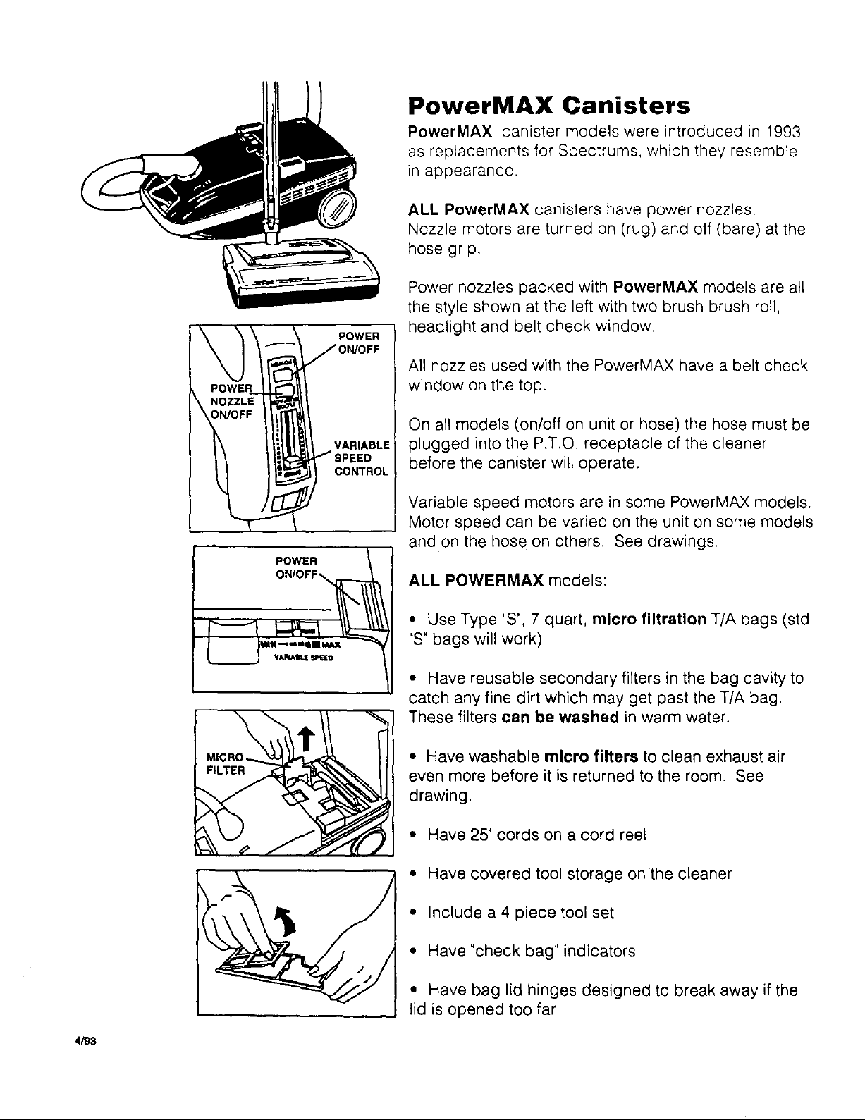
PowerMAX Canisters
PowerMAX canister models were introduced in 1993
as replacements for Spectrums, which they resemble
in appearance.
ALL PowerMAX canisters have power nozzles.
Nozzle motors are turned on (rug) and off (bare) at the
hose grip.
Power nozzles packed with PowerMAX models are all
the style shown at the left with two brush brush roll,
headlight and belt check window,
All nozzles used with the PowerMAX have a belt check
window on the top.
On all models (on/off on unit or hose) the hose must be
plugged into the P.T.O. receptacle of the cleaner
before the canister will operate.
Variable speed motors are in some PowerMAX models.
Motor speed can be varied on the unit on some models
and on the hose on others. See drawings.
ALL POWERMAX models:
• Use Type "S", 7 quart, micro filtration T/A bags (std
"S" bags will work)
• Have reusable secondary filters in the bag cavity to
catch any fine dirt which may get past the T/A bag,
These filters can be washed in warm water.
• Have washable micro filters to clean exhaust air
even more before it is returned to the room. See
drawing.
• Have 25' cords on a cord reel
• Have covered tool storage on the cleaner
• Include a 4 piece tool set
• Have "check bag" indicators
4/93
• Have bag lid hinges designed to break away if the
lid is opened too far
REMOTE
CONTROLS
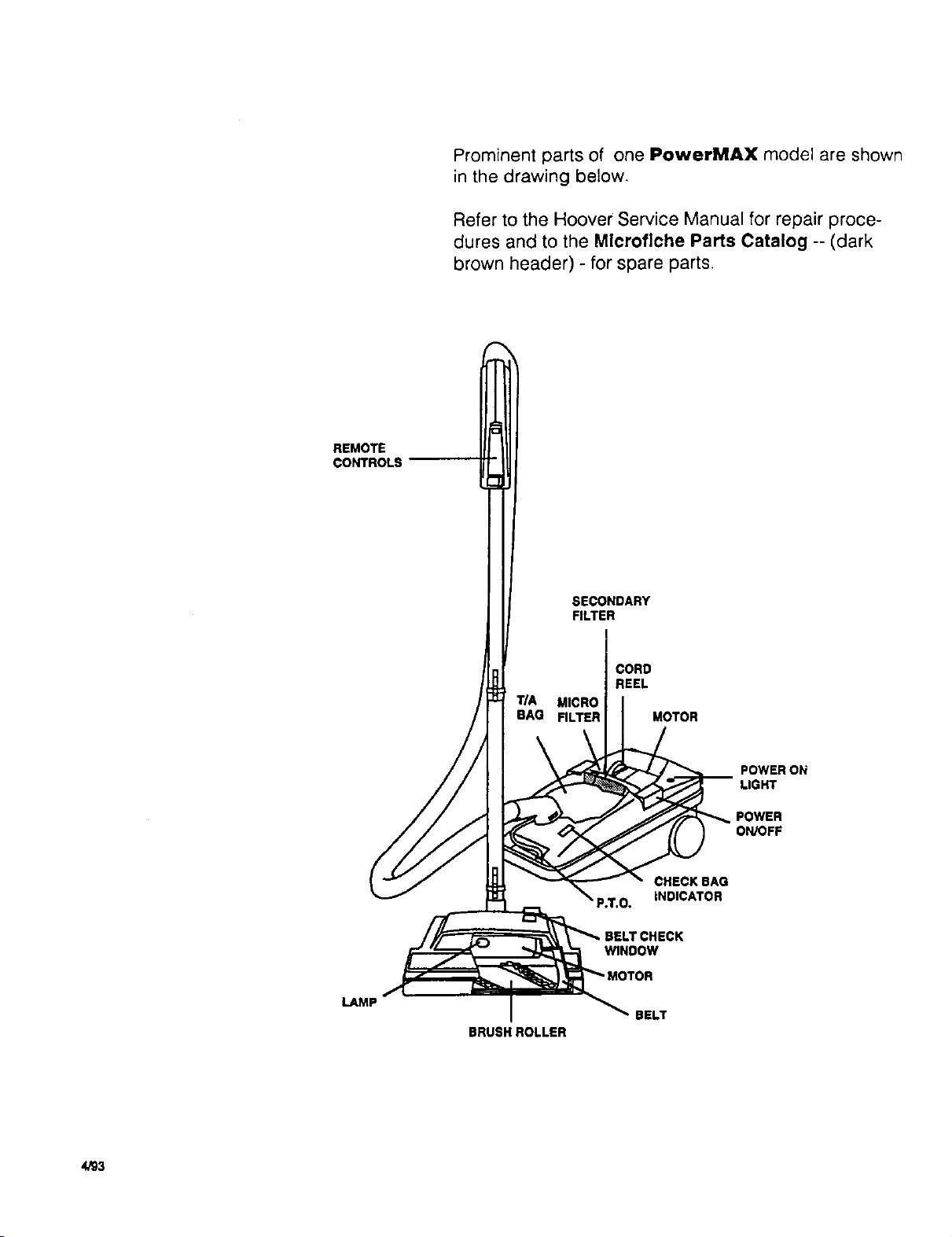
Prominent parts of one PowerMAX model are shown
in the drawing below.
Refer to the Hoover Service Manual for repair proce-
dures and to the Microfiche Parts Catalog -- (dark
brown header) - for spare parts.
SECONDARY
FILTER
LAMP
CORD
REEL
TIA MICRO
BAG FILTER MOTOR
POWERON
LIGHT
POWER
ON/OFF
CHECK BAG
INDICATOR
WINDOW
BELT
BRUSH ROLLER
4/93
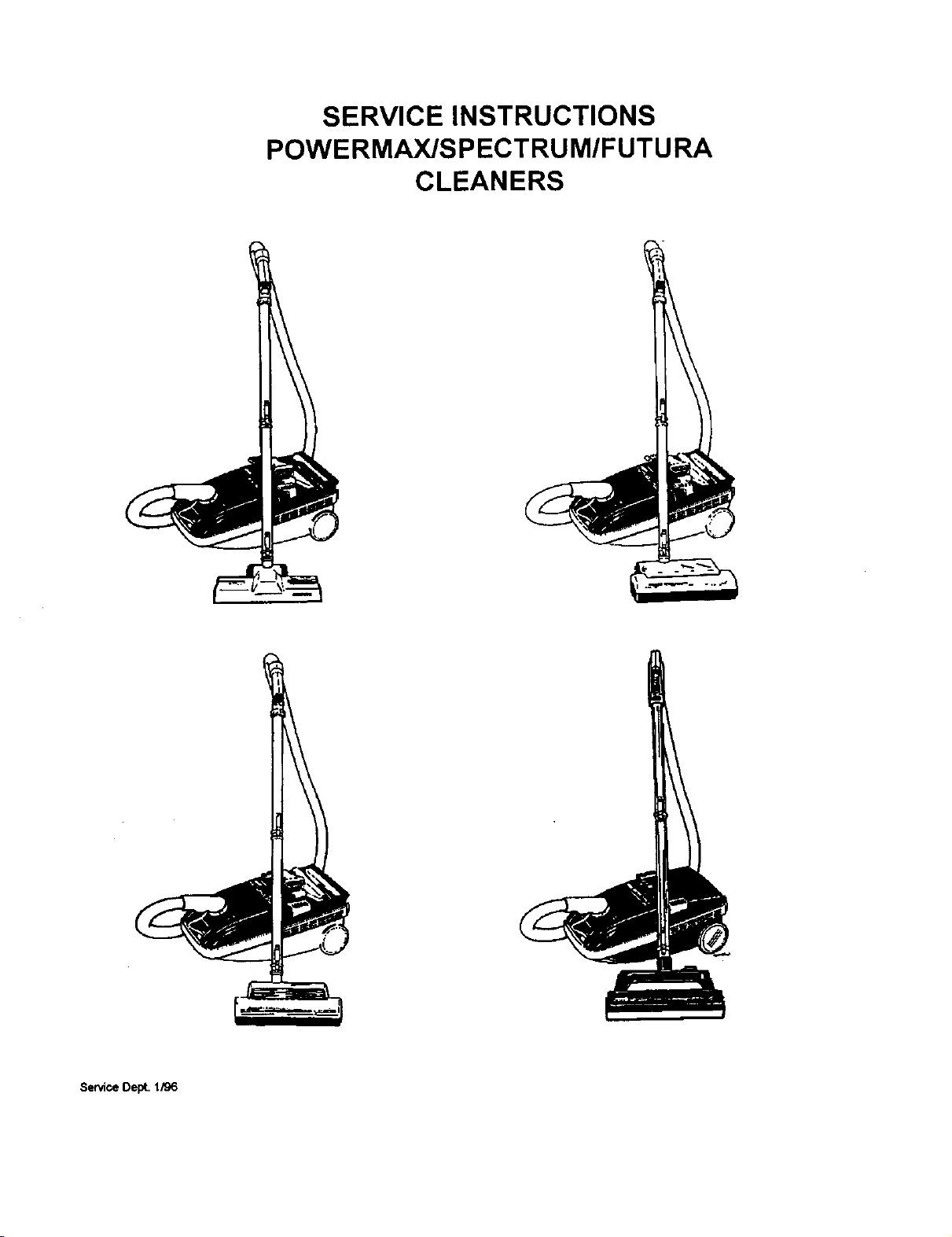
SERVICE INSTRUCTIONS
POWERMAX/SPECTRUM/FUTU RA
CLEANERS
Service Dept. 1/96
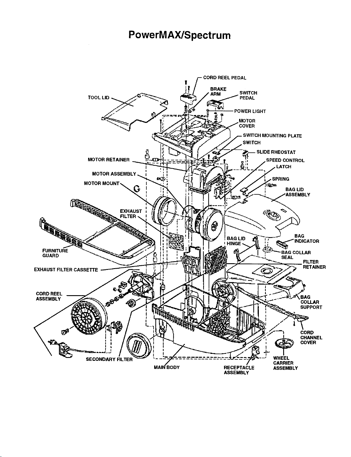
PowerMAX/Spectrum
MOTOR RETAINER
EXHAUST
!
AL
BRAKE
ARM SWITCH
POWER LIGHT
MOTOR
MOUNTING PLATE
SWITCH
HEOSTAT
SPEED CONTROL
,SPRING
BAG UD
BAG LID
BAG
FURNITURE
GUARD
EXHAUST RLTER CASSETTE
CORD REEL __
ASSEMBLY
SECONDARY RLTER
RECEPTACLE
ASSEMBLY
;AG COLLAR
SEAL
RLTER
RETAINER
COLLAR
SUPPORT
CORD
COVER
_. HANNEL
WHEEL
CARRIER
ASSEMBLY
I. General
III, Disassembly
The Futura, Spectrum and PowerMAX clean-
ers are straight air suction type canisters
designed to work efficiently at 120 Volts, 50
Hertz.
Features include:
Full bag indicators
Tool storage (hinged tool covers on Spectrum
and PowerMAX models)
150 ohose swivel at suction inlet
Seven quart throw away bag - Type S
Cord reels on deluxe models
Power Surge on deluxe Spectrum models
Powered nozzles on deluxe models
II. Basic operation
Futura
On Futura models, an on/off switch on the unit
provides power to the unit and powered
nozzle (where applicable). All models are
single speed.
Spectrum
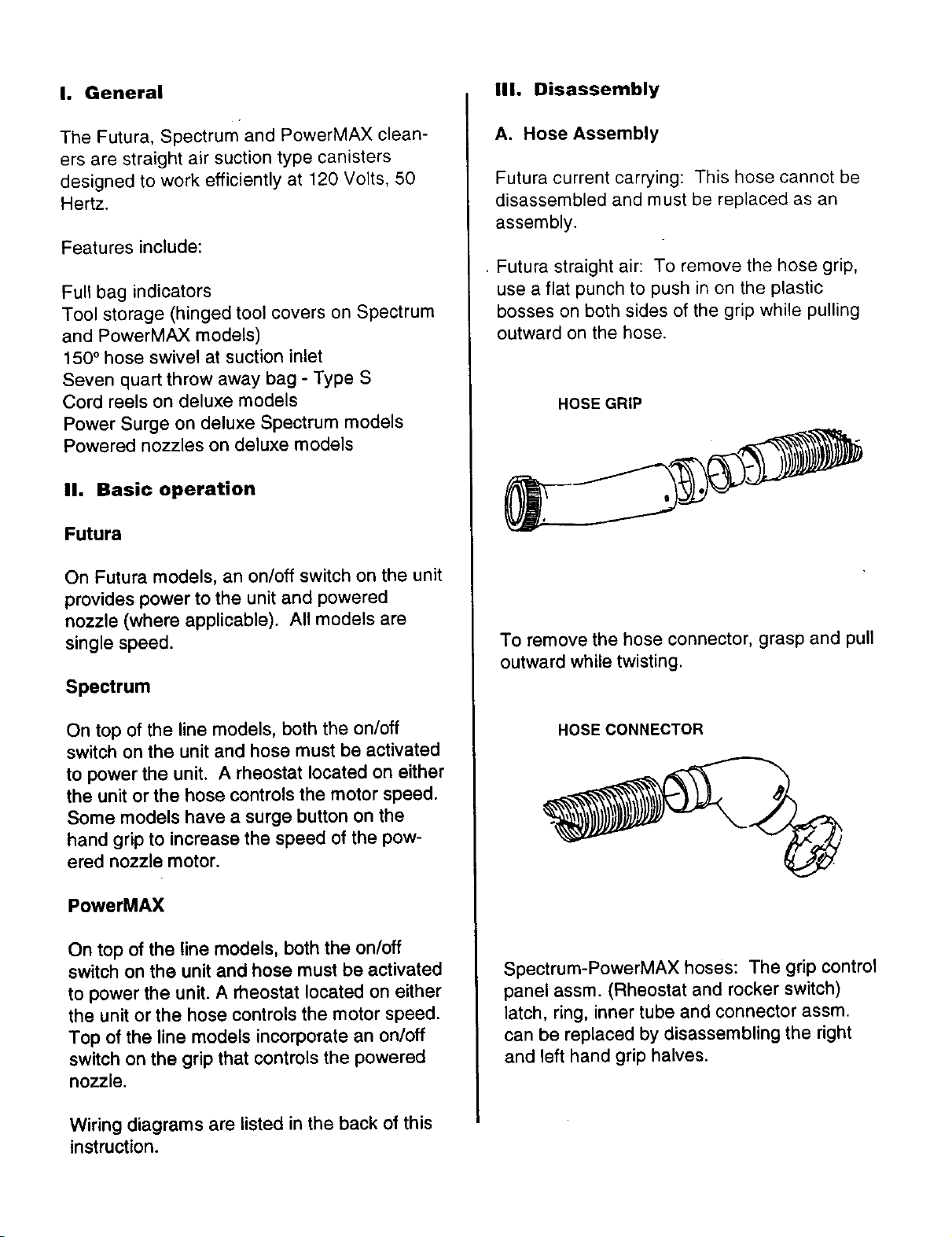
A. Hose Assembly
Futura current carrying: This hose cannot be
disassembled and must be replaced as an
assembly.
• Futura straight air: To remove the hose grip,
use a flat punch to push in on the plastic
bosses on both sides of the grip while pulling
outward on the hose.
HOSE GRIP
To remove the hose connector, grasp and pull
outward while twisting•
On top of the line models, both the on/off
switch on the unit and hose must be activated
to power the unit. A rheostat located on either
the unit or the hose controls the motor speed.
Some models have a surge button on the
hand grip to increase the speed of the pow-
ered nozzle motor.
PowerMAX
On top of the line models, both the on/off
switch on the unit and hose must be activated
to power the unit. A rheostat located on either
the unit or the hose controls the motor speed.
Top of the line models incorporate an on/off
switch on the grip that controls the powered
nozzle.
Wiring diagrams are listed in the back of this
instruction.
HOSE CONNECTOR
Spectrum-PowerMAX hoses: The grip control
panel assm. (Rheostat and rocker switch)
latch, ring, inner tube and connector assm.
can be replaced by disassembling the right
and left hand grip halves.
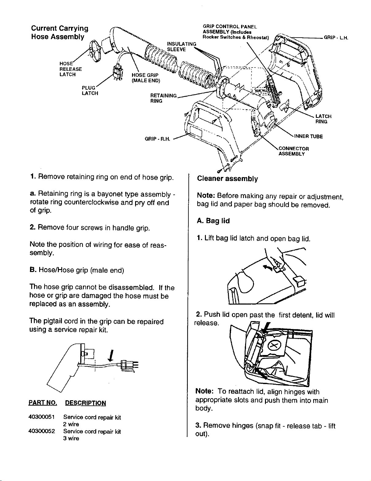
Current
Hose Assembly
INSULATING
SLEEVE
GRIP CONTROL PANEL
ASSEMBLY (Includes
Rocker Switches & Rheostat)
\
._RIP- L,H,
RELEASE
LATCH
PLUG
LATCH
HOSE GRIP
(MALE END)
RE'TAINING
RING
GRIP - R.H.
1. Remove retaining ring on end of hose grip.
a. Retaining ring is a bayonet type assembly -
rotate ring counterclockwise and pry off end
of grip.
2. Remove four screws in handle grip.
Note the position of wiring for ease of reas-
sembly.
,. LATCH
RING
4NER TUBE
ASSEMBLY
Cleaner assembly
Note: Before making any repair or adjustment,
bag lid and paper bag should be removed.
A. Bag lid
1. Lift bag lid latch and open bag lid.
B. Hose/Hose grip (male end)
The hose grip cannot be disassembled. If the
hose or grip are damaged the hose must be
replaced as an assembly.
The pigtail cord in the grip can be repaired
using a service repair kit.
DESCRIPTION
40300051 Service cord repair kit
2 wire
40300052 Service cord repair kit
3wire
2. Push lid open past the first detent, lid will
release.
Note: To reattach lid, align hinges with
appropriate slots and push them into main
body.
3. Remove hinges (snap fit - release tab - lift
out).
4. Remove bag lid latch.
a. Release latch spring on indentation in bag
lid and slide latch out (snap fit).
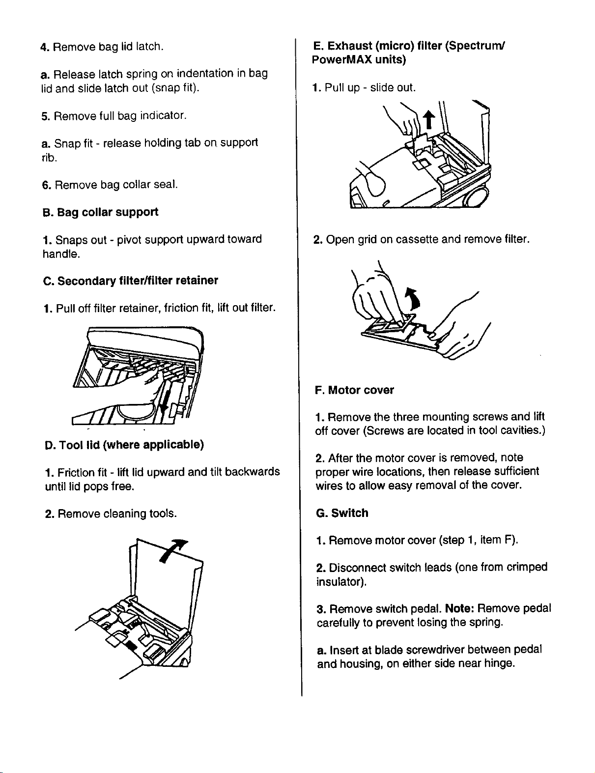
E. Exhaust (micro) filter (Spectrum/
PowerMAX units)
1. Pull up - slide out.
5. Remove full bag indicator.
e. Snap fit - release holding tab on support
rib.
6. Remove bag collar seal.
B. Bag collar support
1. Snaps out - pivot support upward toward
handle.
C. Secondary filter/filter retainer
1. Pull off filter retainer, friction fit, lift out filter.
\
2. Open grid on cassette and remove filter.
F. Motor cover
D. Tool lid (where applicable)
1. Friction fit - lift lid upward and tilt backwards
until lid pops free.
2. Remove cleaning tools.
1. Remove the three mounting screws and lift
off cover (Screws are located in tool cavities.)
2. After the motor cover is removed, note
proper wire locations, then release sufficient
wires to allow easy removal of the cover.
G. Switch
1. Remove motor cover (step 1, item F).
2. Disconnect switch leads (one from crimped
insulator).
3. Remove switch pedal. Note: Remove pedal
carefully to prevent losing the spring.
a. Insert at blade screwdriver between pedal
and housing, on either side near hinge.
 Loading...