

Page 1
R
ec
e
iv
e
r
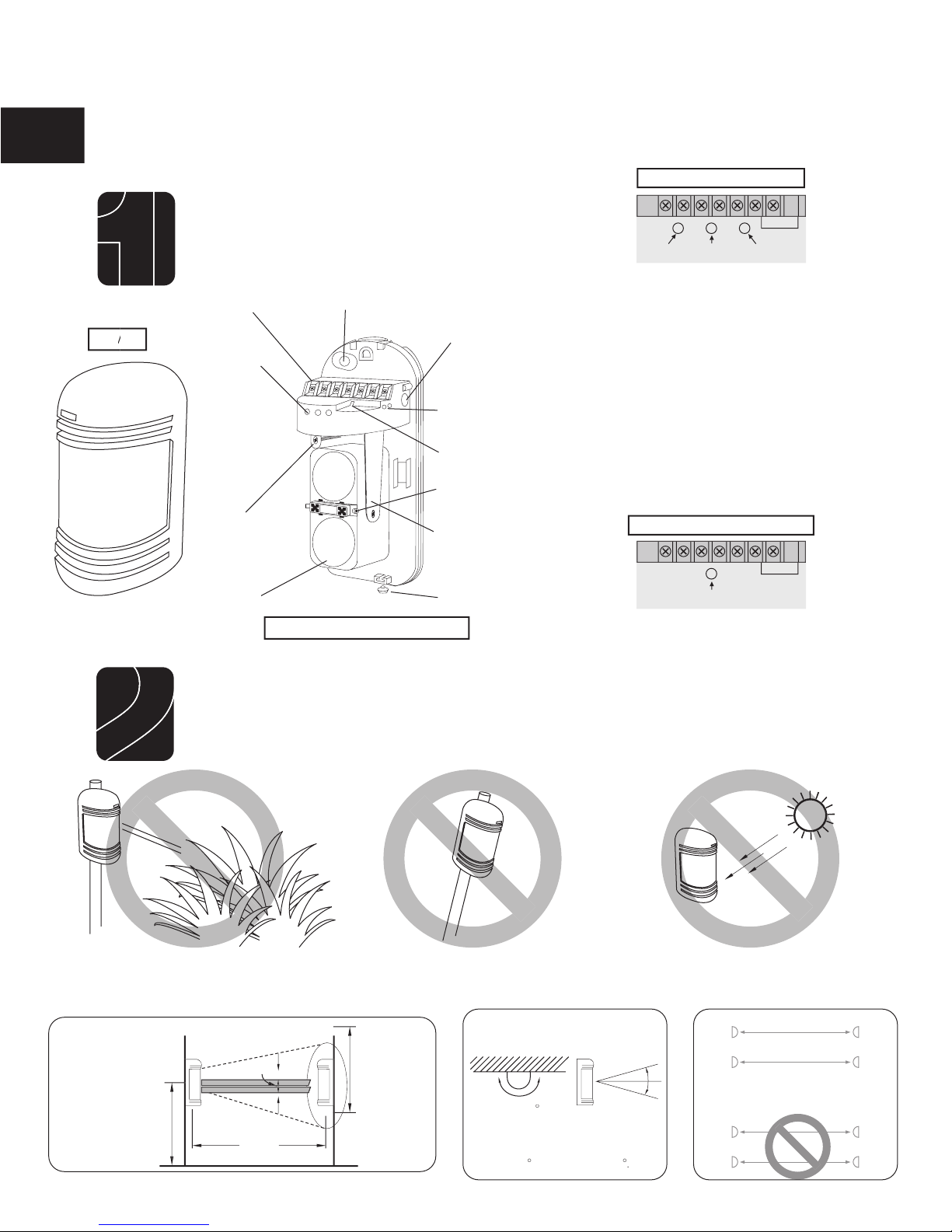
Connection Terminals
Indicators
Wiring Knockout
Vertical
Alignment
Screw
Lens
Cover
Locking Screw
Response Time
Adjustment
Test Points
Tamper
Angle
Adjusting
Do not mount the detector in the following conditions:
Where obstructions (plants, fences, etc.) are
Where the mounting
Where sunlight and headlights shine
The optical axis can be adjusted within horizontal
When using more than one set make
Transmitter
1
Transmitter
Transmitter
Transmitter
LED (green).
LED (green). Use when adjusting
LED (red).
LED (red). ON indicates beam blocked.
Use when setting response time.
TRANSMITTER INDICATOR
2
Page 2
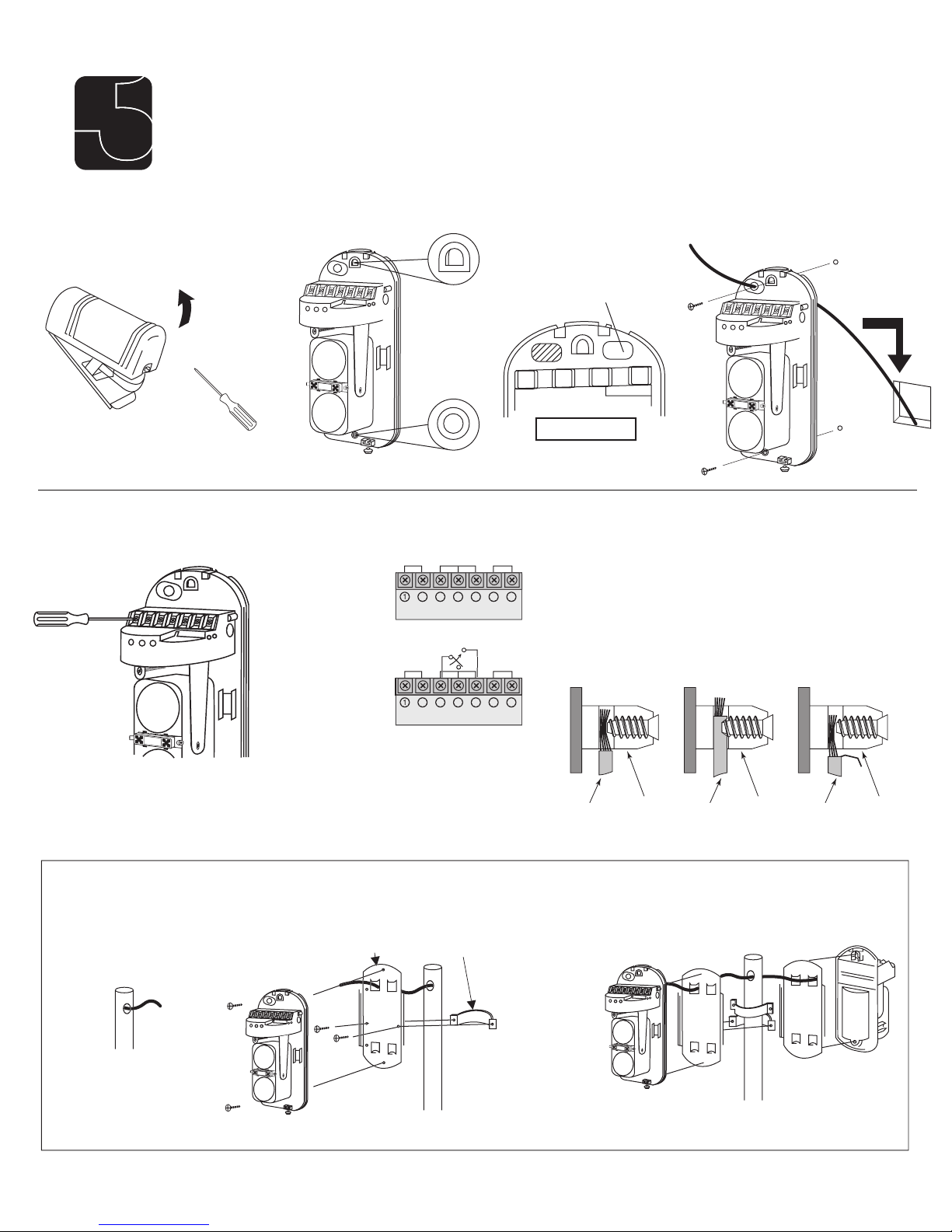
Receiver
Receiver
the wires.
R
e
c
e
i
v
e
r
R
e
c
e
i
v
e
r
Correct Wrong Wrong
Wire
Terminal
Block
Terminal
Block
Terminal
Block
Wire Wire
Wiring Pattern
Transmitter
3
3
3
the wire clamp plates.
produce a short circuit.
R
ec
e
i
v
e
r
Wiring Hole
to mount the unit.
the outer cover.
through.
the terminals
Page 3

4
the opener is turned off before
the terminal blocks. Unplugging the
transformer does not turn power to
the opener OFF.
the other to the SAFETY terminal on the Mighty
Wire from Non-Contact
Sensor (photo beam)
RECEIVER
COM COM
CYCLE
CLOSE
SAFETY
EXIT/
OPEN
SHADOW
LOOP
CLOSE
EDGE
OPEN
EDGE
BLKGRN RED
STALL FORCE
M
I
N
M
A
X
Wire from Non-Contact
Sensor (photo beam)
STALL FORCE
M
I
N
M
A
X
GRN BLK RED
RECEIVER
COM COM
CYCLE
CLOSE
SAFETY
EXIT
OPEN
SHADOW
LOOP
CLOSE
EDGE
OPEN
EDGE
J11
J8
J12
Page 4

5
Re
c
eiver
Re
c
eiver
R
ec
ei
v
er
Re
ce
i
v
er
Viewfi nder
The GOOD indication lamp should be on. (Adjust the
The brighter the red LEVEL indicator light, the
Vertical
Adjustment Screw
To Raise To Lower
ADJUSTMENT
ADJUSTMENT
R
e
c
e
i
v
e
r
Voltmeter or DMM
less than 2ft/s (0.3 - 0.5m/s)
6
Page 5

7
Alarm Output
Tamper Switch
Alignment Angle
Wall or pole
Weight
Appearance
Transmitter
Transmitting
Alarm indication lamp is ON
Transmitter LED does not light.
Alarm LED does not light,
When the beams are blocked, the receiver
The alarm indication lamp of receiver is
transmitter and the receiver.
transmitter and the receiver.
After installation, confi rm correct
8
 Loading...