

Page 1
LIBRETTO ISTRUZIONI
IT
INSTRUCTIONS BOOKLET
NOTICE D’EMPLOI ET ENTRETIEN
GB
FR
mod.
Page 2
IT
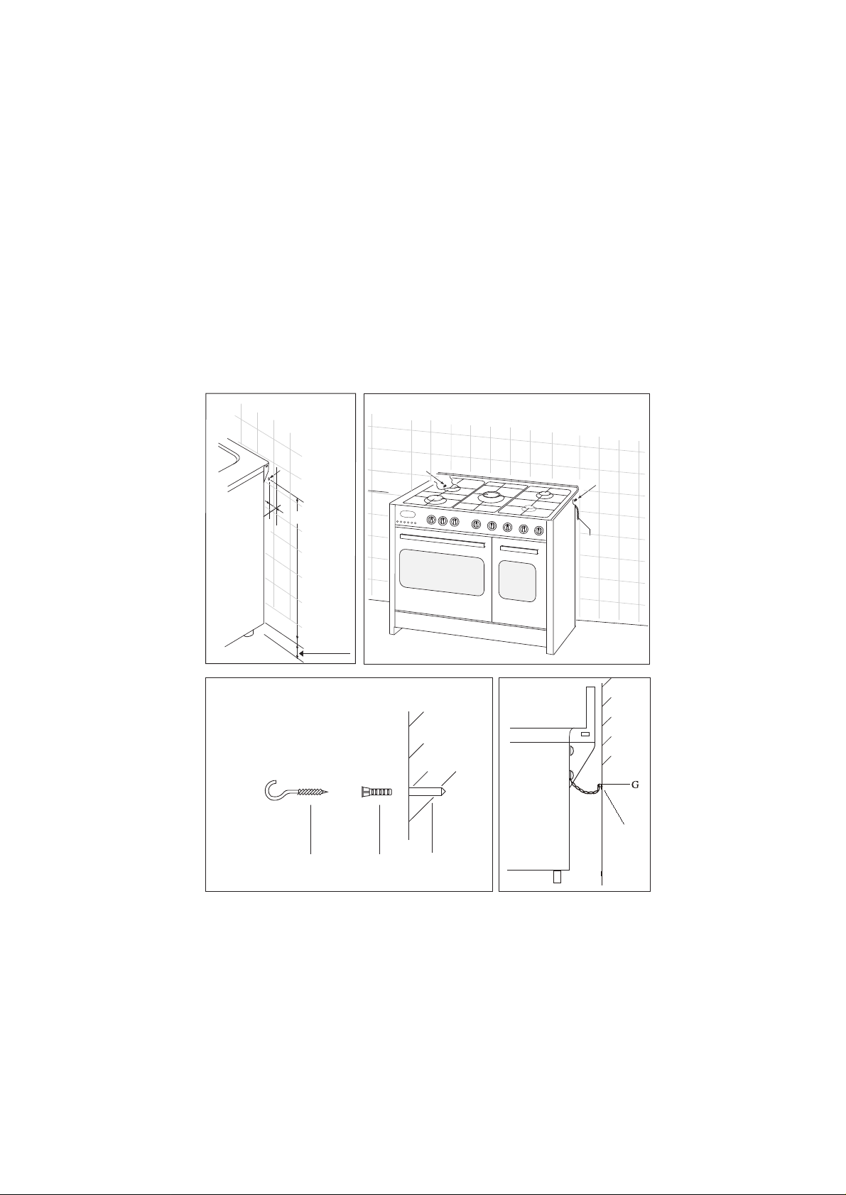
Fissare la cucina al muro
Praticare due fori nella parete a circa 70 cm dal filo inferiore dei fianchi della cucina (come indicato nella fig. A posizione F,
e che siano nascosti dall' ingombro della cucina (vedere fig. B).
Inserire la parte R (tassello) nei fori F ed avvitare il gancio G nella parte R (fig. C).
Fissare la catena al gancio G come indicato nella fig. D posizione C.
Fig. A
Fig. C
Posizione F = fori
ø 6 mm
60 mm +/- 3
86 cm +/- 5
H - piedi
regolabili
Fig. B
Posizione
2
Posizione
1
Gancio
Parete
Fig. D
Parete
posizione C
G
R
F
2
Page 3
INFORMAZIONI GENERALI
DESTINATE ALL'UTILIZZATORE
AVVERTENZE AMBIENTALI
Imballaggio rifiuti
Non gettate l'imballaggio del vostro apparecchio nella
spazzatura, bensì selezionate i vari materiali (ad es. lamina,
cartone, polistirolo) secondo le prescrizioni locali per lo
smaltimento rifiuti.
IT
funzionamenti, prima di rivolgersi al Servizio Assistenza Autorizzato,
consigliamo vivamente di effettuare i controlli indicati sopra.
UN SOLO NUMERO TELEFONICO PER OTTENERE
ASSISTENZA
Qualora il problema dovesse persistere, componendo il “Numero
Utile” sotto indicato, sarà messo in contatto direttamente, con il
Servizio Assistenza Tecnica Autorizzato che opera nella Sua zona
di residenza.
NUMERO UTILE
Assistenza Tecnica
Questo prodotto risponde alle esigenze delle direttive comunitarie:
- 73/23/CEE relativa alla "bassa tensione".
- 89/336/CEE relativa alla "perturbazione elettromagnetica".
- 90/396/CEE relativa agli “Apparecchi a gas”
- 89/109/CEE relativa ai "materiali in contatto con gli alimenti".
- Le sopra citate Direttive sono inoltre conformi alla Direttiva
93/68/CEE.
- Questo apparecchio dovrà essere destinato solo all'uso per il
quale è stato espressamente progettato, come "apparecchio
per la cottura" ad uso domestico.
GENTILE CLIENTE,
• Vi invitiamo a leggere attentamente queste istruzioni prima
dell'uso e di conservarle per poterle consultare in caso di
necessità.
• Gli elementi dell'imballaggio (sacchetti in plastica, polistirolo
espanso, ecc.) non dev ono essere lasciati alla portata dei bambini
in quanto potenzialmente pericolosi.
SERVIZIO ASSISTENZA CLIENTI
Prima di chiamare il servizio di Assistenza Tecnica
In caso di mancato funzionamento dell' apparecchio vi
consigliamo di:
— verificare il buon inserimento della spina nella presa di corrente;
— verificare che l’afflusso di gas sia regolare.
Nel caso non si individui la causa di mal funzionamento:
spegnere l’apparecchio non manometterlo e chiamare il Servizio
di Assistenza Tecnica.
CERTIFICATO DI GARANZIA: cosa fare?
Il Suo prodotto è garantito, alle condizioni e nei termini riportati
sul certificato inserito nel prodotto ed in base alle previsioni del
decreto legislativo 24/02, fino a 24 mesi decorrenti dalla data di
consegna del bene.
Il certificato di garanzia dovrà essere da Lei conservato, debitamente
compilato, per essere mostrato al Servizio Assistenza Tecnica
Autorizzato, in caso di necessità, unitamente ad un documento
fiscalmente valido rilasciato dal rivenditore al momento dell’acquisto
(bolla di consegna, fattura, scontrino fiscale, altro) sul quale siano
indicati il nominativo del rivenditore, la data di consegna, gli estremi
identificativi del prodotto ed il prezzo di cessione.
Il Servizio di Assistenza Tecnica Autorizzato, verificato il diritto
all’intervento, lo effettuerà senza addebitare il diritto fisso di
intervento a domicilio, la manodopera ed i ricambi che
sono totalmente gratuiti.
ESTENSIONE DELLA GARANZIA FINO A 5 ANNI: come?
Le ricordiamo inoltre che sullo stesso certificato di garanzia
convenzionale Lei troverà le informazioni ed i documenti necessari
per prolungare la garanzia dell’apparecchio sino a 5 anni e così,
in caso di guasto, non pagare il diritto fisso di intervento a domicilio,
la manodopera ed i ricambi.
Per qualsiasi informazione necessitasse, La preghiamo rivolgersi
al numero telefonico del Servizio Clienti 0392086811.
199.123.123
MATRICOLA DEL PRODOTTO. Dove si trova?
È importante che comunichi al Servizio Assistenza Tecnica
Autorizzato la sigla del prodotto ed il numero di matricola che
troverà sul certificato di garanzia oppure sulla targa matricola
posta all' interno del cassetto inferiore dell' apparecchio.
In questo modo Lei potrà contribuire ad evitare trasferte inutili del
tecnico, risparmiando oltretutto i relativi costi.
CONSIGLI ED AVVERTIMENTI DI
ORDINE GENERALE
ATTENZIONE:
- Non dimenticate, prima di utilizzare l'apparecchio, di togliere le
protezioni in plastica che proteggono alcune parti (cruscotto,
parti in inox, ecc...)
- Non utilizzare l'apparecchio per riscaldare l’ambiente.
- Quando non si usa l'apparecchio si raccomanda di staccare
corrente e di chiudere il rubinetto generale del gas.
IN CASO D'INCENDIO:
• In caso d'incendio, chiudere il rubinetto generale di alimen-
tazione gas, staccare la corrente; non gettare mai acqua
sull'olio in fiamme o che sta friggendo.
• Non tenere prodotti infiammabili o bottiglie aerosol vicino
all'apparecchio, e non vaporizzare vicino ai bruciatori accesi.
PER LA SICUREZZA DEI VOSTRI BAMBINI E DI VOI STESSI
• Evitare di tenere sull'apparecchio degli oggetti attrattivi per i
bambini.
• Tenere i bambini lontani dall'apparecchio; non dimenticate che
alcune parti dell'apparecchio o delle pentole utilizzate, diventano
molto calde e pericolose, sia durante il funzionamento che
durante il tempo necessario al raffreddamento dopo lo spegnimento.
• Fare attenzione ai manici dei tegami, tener li disposti in modo
che i bambini non rovescino le pentole.
• Non indossare indumenti o accessori ampi quando i bruciatori
sono accesi; l'incendio del materiale tessile può causare serie
ferite alla persona.
ATTENZIONE FORNO:
Quando il forno o il grill sono in funzione, le parti accessibili
possono diventare molto calde, è opportuno tenere i bambini
lontani dall'apparecchio.
- Evitare di cuocere gli alimenti sulla base del forno.
- In caso d'utilizzo negligente nelle vicinanze delle cerniere della
porta forno, esiste il pericolo di ferirsi le mani.
- Non permettere ai bambini di sedersi o giocare con la por ta
forno. Non utilizzare la porta come sgabello.
CASSETTO INFERIORE
Non inserire materiali infiammabili o utensili in plastica nel cassetto
(situato sotto la cavità forno).
ANOMALIE E MALFUNZIONAMENTI: a chi rivolgersi?
Per qualsiasi necessità il centro assistenza autorizzato è a Sua
completa disposizione per fornirLe i chiarimenti necessari;
comunque qualora il Suo apparecchio presenti anomalie o mal
3
Page 4

IT
USO DEL PIANO DI LAVORO
USO DEI BRUCIATORI A GAS
Sulla mascherina sono indicati i seguenti simboli vicino ad ogni
manopola:
- Disco pieno rubinetto chiuso
- Fiamma grande apertura massima
- Fiamma piccola apertura minima
La posizione del minimo si trova al termine della rotazione antioraria
della manopola. Tutte le posizioni di funzionamento de v ono essere
scelte tra le posizioni di minimo e massimo, mai tra il massimo e
la chiusura.
I bruciatori sono dotati di dispositivi disicurezza contro fughe di
gas a termocoppia. Questo dispositivo provvede a bloccare l’uscita
del gas nel caso in cui la fiamma del bruciatore si spenga durante
il funzionamento.
Accensione dei bruciatori
Per accendere uno dei bruciatori, procedere come segue:
• ruotare la manopola corrispondente in senso antiorario
fino al simbolo della fiamma grande;
• premere la manopola a fondo per azionare l’accensione
automatica del gas ;
• mantenere premuta la manopola per circa 10 secondi con la
fiamma accesa per consentire il riscaldamento della
termocoppia di sicurezza.
• rilasciare la manopola, verificando che l’accensione sia
avvenuta in modo stabile.
In caso contrario, ripetere l’operazione.
In mancanza di corrente elettrica, il bruciatore può essere acceso
anche con un fiammifero.
RISPARMIO ENERGETICO
• Il diametro del fondo della pentola deve essere adeguato al
diametro del bruciatore. La fiamma del bruciatore non de ve mai
fuoriuscire dal diametro della pentola.
• Utilizzare pentole con fondo piatto.
• Cuocere possibilmente con coperchio. Questo consente di
utilizzare potenze più basse.
• Cuocere verdure, patate, ecc., con poca acqua per ridurre i
tempi di cottura.
Bruciatore diametro min. diametro max
Grande (rapido) 180 mm. 220 mm.
Medio (semirapido) 120 mm. 200 mm.
Tripla corona 220 mm. 260 mm.
USO DEL FORNO ELETTRICO
PRIMA PARTE
Alla prima accensione del forno può svilupparsi fumo di odore
acre, causato dal primo riscaldamento del collante dei pannelli
d’isolamento avvolgenti il forno (è opportuno riscaldarlo alla
massima temperatura per una durata di 30-40 minuti a porta
chiusa). Si tratta di un fenomeno assolutamente normale e, in
caso si verificasse, occorre attendere la cessazione del fumo
prima di introdurre le vivande.
Il forno è generalmente corredato di: g riglia per la cottura dei cibi
riposti in teglie o appoggiate direttamente sulla griglia, leccarda
per la cottura di dolci, biscotti, o per raccogliere i sughi ed i grassi
di cibi riposti direttamente sulla griglia.
Nota: nelle seguenti tabelle sono riportate le indicazioni più
importanti per la cottura di alcuni dei principali piatti. I tempi di
cottura consigliati in queste tabelle sono indicativi. Siamo certi
che dopo poche prove potrete apportare quelle modifiche necessarie per ottenere i risultati desiderati.
Tabelle di cottura sistema tradizionale
Preparazione Temp. °C. Minuti
Pesce 180-240 sec. dimensioni
Carne
Arrosto di bue 250 30 per kg.
Arrosto di vitello 200-220 60 per kg.
Pollo 200-240 50 circa
Anatra od oca 220 sec. peso
Cosciotto di montone 250 30 per kg.
Arrosto di maiale 250 60 per kg.
Soufflets 200 60 per kg.
Dolci (Pasticceria)
Panfrutto 160 50-60
Savoiardi 160 30-50
Pasta frolla 200 15
Pasta sfoglia 250 15
Torta di frutta 200-220 30
Meringhe 100 60
Sformato 220 30
4 quarti 120-140 60
Brioches 160-180 45
Tabelle di cottura ad aria calda
Preparazione Temp. °C. Minuti Peso kg.
Primi piatti
Lasagne al forno 200-220 20-25 0,5
Pasta al forno 200-220 25-30 0,5
Riso alla Creola 200-230 20-25 0,5
Pizza 210-230 30-45 0,5
Carne
Arrosto di vitello 160-180 65-90 1-1,2
Arrosto di maiale 160-170 70-100 1-1,2
Arrosto di bue 170-190 40-60 1-1,2
Arrosto di manzo 170-180 65-90 1-1,2
Roast-Beef 180-190 40-45 1-1,5
Arrosto di agnello 140-160 100-130 1,5
Pollo arrosto 180 70-90 1-1,2
Anitra arrosto 170-180 100-160 1,5-2
Oca arrosto 160-180 120-160 3-3,5
Tacchino arrosto 160-170 160-240 5 ca.
Coniglio arrosto 160-170 80-100 2 ca.
Lepre arrosto 170-180 30-50 2 ca.
Pesci 160-180 sec. peso
Dolci (Pasticceria)
Torta di frutta 180-200 40-50
Ciambella 160-180 35-45
Torta Margherita 200-220 40-45
Pan di Spagna 200-230 25-35
Schiacciata d’uva 230-250 30-40
Brioches 170-180 40-60
Strûdel 160 25-35
Sfogliatine dolci 180-200 20-30
Frittelle di mele 180-200 18-25
Budino di savoiardi 170-180 30-40
Biscotti di Savoia 150-180 50-60
Toast 230-250 7
Pane 200-220 40
4
Page 5

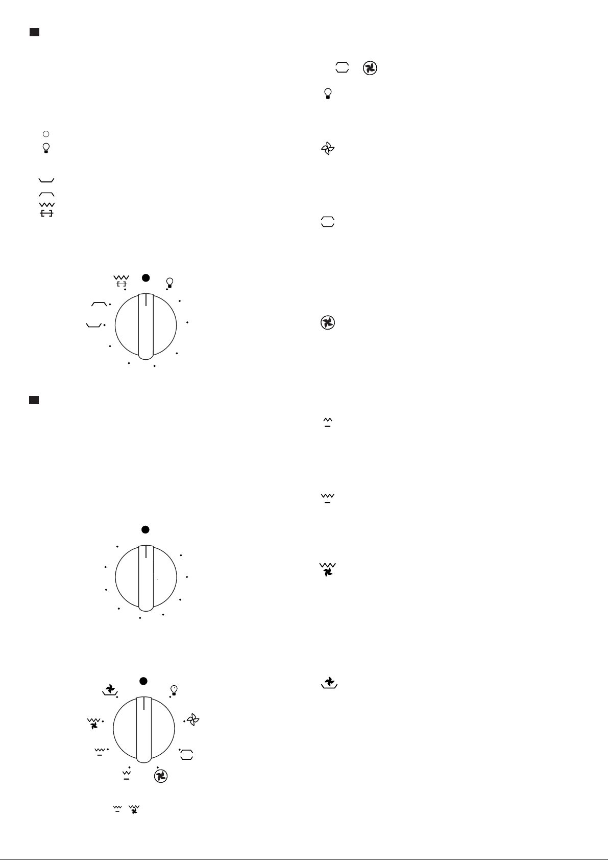
1 FORNI A CONVEZIONE NATURALE (forno piccolo)
Il forno è dotato di:
• una resistenza suola;
• una resistenza cielo.
Ruotando in senso orario la manopola del termostato è possibile
selezionare la temperatura desiderata nel forno e, secondo i
modelli, una o più funzioni:
Forno spento
Luce forno
60 ÷ max Inserzione della resistenza superiore + inferiore
Inserzione della resistenza inferiore
Inserzione della resistenza superiore
Inserzione del grill + girarrosto
IT
ATTENZIONE:
La temperatura indicata sul cruscotto corrisponderà con la temperatura mantenuta nel centro del forno solo quando le funzioni
selezionate sono oppure .
Ruotata la manopola di comando su questa posizione, la lampada
resta accesa per tutte le operazioni che seguono.
Scongelamento con ventilatore
Questa posizione permette di far circolare l’aria a temperatura
ambiente intorno al cibo surgelato facendolo così scongelare
senza modificare od alterare il contenuto proteico.
60
90
max
130
200
170
NOTA:
Il forno deve sempre essere usato a porta chiusa.
2 FORNO MULTIFUNZIONE (forno grande)
Il forno è dotato di:
• una resistenza suola;
• una resistenza cielo;
• una resistenza circolare che avvolge il ventilatore.
N.B.: L’inserimento di qualsiasi funzione avviene sempre dopo aver
posizionato la manopola del termostato in corrispondenza di una
temperatura desiderata.
Manopola termostato forno
Ruotando in senso orario questa manopola si può ottenere una
temperatura del forno compresa tra 50 e MAX°C.
max
50
225
75
200
100
175
Manopola commutatore forno
Ruotando in senso orario la manopola del commutatore, è possibile
selezionare una delle seguenti funzioni che qui di seguito riportiamo.
150
125
Convezione naturale
Sono in funzione la resistenza suola e la resistenza cielo forno.
È la cottura tradizionale, ottima per arrostire cosciotti, selvaggina,
ideale per biscotti, mele al forno e per rendere i cibi molto croccanti.
Si ottengono buoni risultati per cotture su un ripiano con regolazione
della temperatura da 50 a MAX°C.
Forno ventilato
Sono in funzione il ventilatore e la resistenza circolare. L’aria calda
regolabile da 50 a MAX°C viene uniformemente ripartita sui diversi
ripiani; è ideale per cuocere contemporaneamente diversi tipi di
cibo (carne, pesce) senza miscelare sapori e odori. Cottura delicata
indicata per pan di Spagna, torte Margherita, pasta sfoglia, ecc.
Inserimento grill medio
In questa posizione viene inserita la resistenza del grill medio a
raggi infrarossi. Serve per grigliare o gratinare piatti tradizionali
di dimensioni piccole. Questa funzione può essere usata tra 50
e MAX°C.
Inserimento grill totale
In questa posizione viene inserita la resistenza del grill a raggi
infrarossi. Serve per grigliare o gratinare piatti tradizionali. La porta
forno deve essere chiusa e il termostato va messo tra 180÷200°C
come massima temperatura.
Grill totale ventilato
L’aria, riscaldata dalla resistenza grill, viene aspirata dal ventilatore
che la riversa sulle vivande. Il grill ventilato sostituisce egregiamente
il girarrosto e garantisce ottimi risultati con pollame, salsicce e
carni rosse, anche in quantità rilevante. Il termostato va messo ,
come temperatura massima, tra 180÷200°C .
Utilizzazione del forno
Il forno deve sempre essere usato a porta chiusa.
Quando si utilizzano le funzioni
posizionare la manopola del termostato tra 180 ÷ 200°C come
massima temperatura.
Resistenza suola ventilata
L’aria, riscaldata dalla resistenza suola, viene aspirata dal ventilatore
che la riversa sulle vivande. Questa funzione può essere utilizzata
per sterilizzare vivande. Questa funzione può essere usata tra 50
e MAX°C.
Nota:
Per tutte le operazioni descritte al punto 1 e 2, si determina l’inserimento
dell’illuminazione interna del forno.
Una spia posta sul cruscotto rimane accesa finché la temperatura
non è stata raggiunta, in seguito si accenderà ad intermittenza.
5
Page 6
USO DEL GRILL:
Posizionare la griglia porta piatto al terzo gradino partendo dal
basso del forno, a 12 cm circa dalla superficie.
L’utilizzatore potrà cambiare i gradini, a seconda dei suoi gusti
personali ed a seconda delle diverse necessità dei cibi. Prima di
infornare, lasciare riscaldare per 5 minuti
GIRARROSTO
Per il funzionamento del girarrosto, ripetere le operazioni descritte
nel paragrafo 1 di pagina 5 posizione .
USO DEL GIRARROSTO
- Infilare il pollo o la parte da arrostire nello spiedo L avendo
cura d’immobilizzarlo tra le due forchette F e di equilibrarlo, in
modo da evitare sforzi inutili al motoriduttore R (fig. 3).
- Mettere lo spiedo sul supporto G, dopo aver introdotto la sua
estremità opposta nel foro P del motorino R (fig. 3).
- Mettere la leccarda con un po’ d’acqua sotto lo spiedo.
- Per togliere lo spiedo, operare in modo contrario utilizzando
la manopola A ed un guanto di protezione in lana isolante (fig
3).
R
P
2
2
F
L
1
A
Fig. 3
1
G
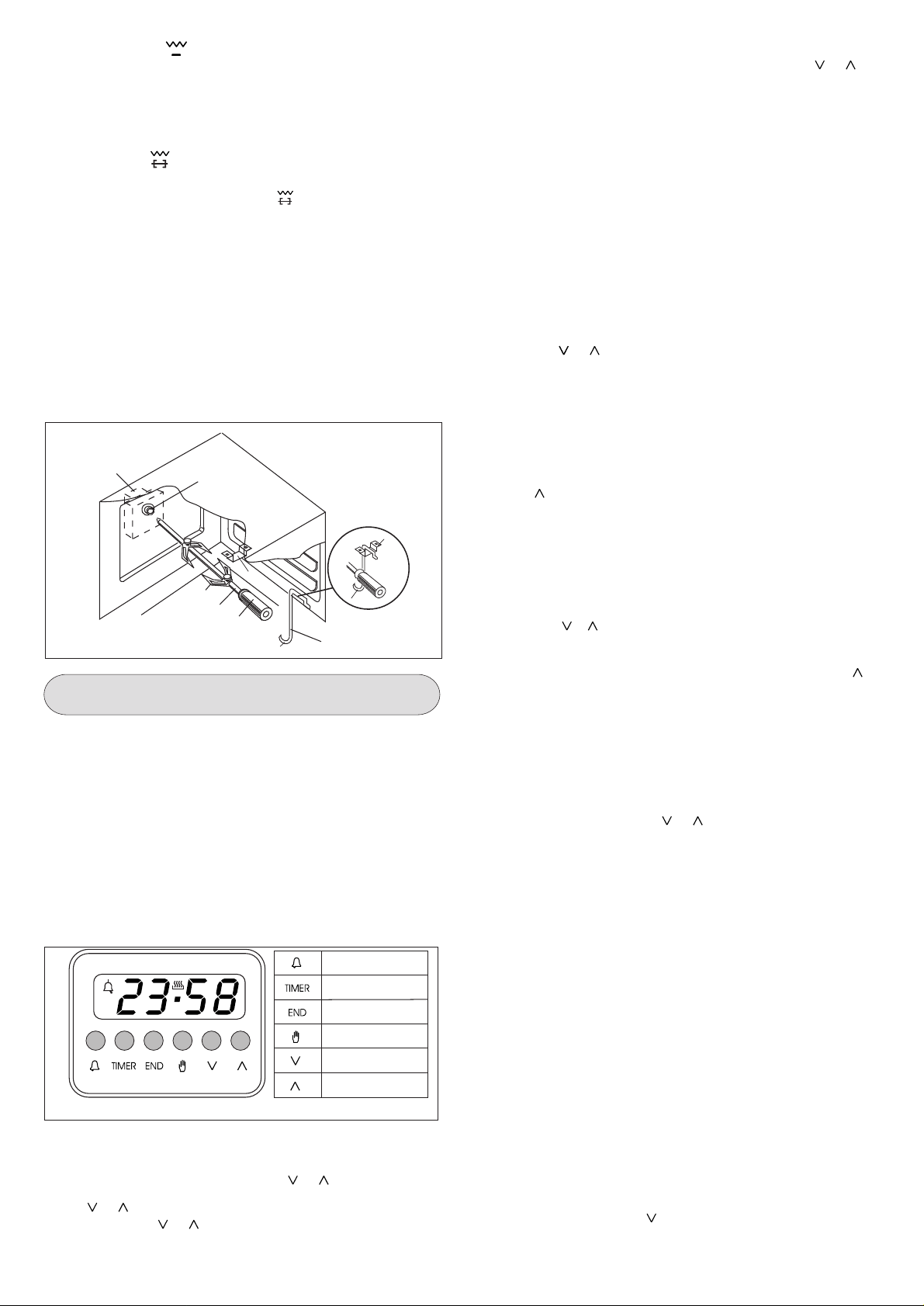
ISTRUZIONI PER L’USO DEI DISPOSITIVI DI
CONTROLLO (fig. 4)
Caratteristiche
Orologio 24 ore con programma automatico e contaminuti.
Funzioni
Durata cottura, fine cottura, posizione manuale, orologio, contaminuti, tempi impostabili fino a 23 ore 59 minuti
Visualizzazione
Display fluorescente a 4 cifre di 7 segmenti per l’indicazione
dell’ora e dei tempi di cottura.
Durata cottura o funzione manuale = simbolo pentola
Funzione automatica = AUTO
Contaminuti = simbolo campana
A seconda delle funzioni prescelte si illumina il simbolo corrispondente.
Contaminuti
A
U
T
O
Fig. 4
Programmazione
La programmazione avviene premendo il tasto della funzione
desiderata e dopo averlo rilasciato è sufficiente che entro 5 secondi
si inizi ad impostare il tempo con i tasti e .
Tasto e
Azionando i tasti e il tempo aumenta o decresce ad una
velocità variabile a seconda della durata di pressione esercitata
sul tasto.
Tempo di cottura
Fine cottura
Manuale
Togliere tempo
Aggiungere tempo
IT
Impostazione dell’ora
Premendo contemporaneamente il tasto manuale e o , si
imposta l’ora desiderata. Con tale operazione vengono cancellati
eventuali progr ammi precedentemente impostati e i contatti sono
disinseriti.
Funzionamento manuale
Azionare il tasto manuale, i contatti del relais sono inseriti, il
simbolo AUTO si spegne, il simbolo pentola si illumina. Il funzionamento manuale può avvenire soltanto al termine della programmazione automatica o dopo averla cancellata.
Funzionamento automatico
Azionando il tasto di durata o fine cottura il programmatore si
commuta automaticamente dalla funzione manuale a quella
automatica.
Funzionamento semiautomatico con durata cottura
Premere il tasto durata cottura ed impostare il tempo desiderato
con il tasto o . Il simbolo AUTO si illumina in permanenza
ed altrettanto il simbolo di durata cottura. Il relais si inserisce
immediatamente. Quando il tempo di fine cottura coincide con
l’ora, il relais ed il simbolo di durata cottura si disinseriscono, si
mette in funzione il segnale acustico ed il simbolo AUT O lampeggia.
Funzionamento semiautomatico con fine cottura
Premere il tasto di fine cottura. Verrà visualizzata sul display l’ora
del momento. Selezionare il tempo di fine cottura desiderato con
il tasto . I simboli AUTO e durata cottura si illuminano in
permanenza. I contatti del relais si inseriscono.
Quando il tempo di fine cottura coincide con l’ora, il relais ed il
simbolo di durata cottura si disinseriscono. Allo scadere del tempo
di cottura il simbolo AUTO lampeggia, si mette in funzione il
segnale acustico e sia il simbolo di durata sia il relais si spengono.
Funzionamento automatico con durata e fine cottura
Premere il tasto di durata e selezionare la durata cottura desiderata
con il tasto o . I simboli AUTO e durata si illuminano in
permanenza. Il relais si inserisce. Premere il tasto di fine cottura.
Sul display compare il tempo di fine cottura più prossimo. Selezionare il tempo di fine cottura desiderato mediante il tasto . Il
relais ed il simbolo di durata si disinseriscono. Il simbolo si illumina
di nuovo
quando l’ora coincide con il tempo di inizio cottura. Allo scadere
del tempo di cottura il simbolo AUTO lampeggia. Si mette in
funzione il segnale acustico e sia il simbolo di durata che il relais
si spengono.
Contaminuti
Premere il tasto contaminuti e selezionare il tempo di cottura
desiderato mediante il tasto o .
Durante il funzionamento del contaminuti si illumina il simbolo
campana. Al termine del tempo impostato si mette in funzione
il segnale acustico ed il simbolo campana si spegne.
Segnale acustico
Il segnale acustico si mette in funzione al termine di una programmazione o della funzione contaminuti ed ha una durata di 15
minuti. Per interromperlo pr ima, si dovrà premere uno qualsiasi
dei tasti delle funzioni.
Inizio programma e controllo
Il programma ha inizio circa 4 secondi dall’impostazione. In qualsiasi
momento è possibile controllare il programma impostato premendo
il tasto corrispondente.
Errore di programmazione
Si ha un errore di programmazione se l’ora indicata dall’orologio
è compresa tra l’ora di inizio cottura e l’ora di fine cottura. L’errore
d’impostazione può essere corretto variando la durata o il tempo
di fine cottura, in presenza di un errore di impostazione i relais
sono disinseriti.
Annullamento di un programma
Si può cancellare un programma premendo il tasto di durata
cottura e di seguito il tasto fino a che sul display non comparirà
l’indicazione 00 00. Al termine di un programma impostato , questo
si cancella automaticamente.
6
Page 7
IT
SECONDA PARTE
MANUTENZIONE E PULIZIA
Prima di procedere alla pulizia, chiudere il rubinetto
dell'impianto gas generale e staccare la spina dalla presa di
corrente o togliere la corrente della linea di alimentazione a
mezzo dell'interruttore generale dell'impianto elettrico.
Evitare di pulire le superfici dell'apparecchio quando le stesse
sono ancora calde.
SUPERFICI SMALTATE
Pulire con una spugna inumidita in acqua e sapone.
Le macchie di grasso possono essere tolte facilmente con acqua
calda o con un prodotto specifico, reperibile in commercio per la
pulizia dello smalto. Evitare i prodotti contenenti sostanz e abrasive .
Evitare di lasciare sullo smalto sostanze acide o alcaline (succo
di limone, aceto, sale, ecc.). Gli apparecchi in acciaio inox devono
essere puliti con appositi detergenti per superfici in acciaio inox.
Questi detergenti vanno applicati con un panno morbido.
GRIGLIE E BRUCIATORI
Per procedere alla pulizia dei bruciatori del piano di lavoro, occorre
estrarli dalla loro sede sfilandoli verso l'alto, e metterli per una
decina di minuti in una soluzione di acqua calda con l'aggiunta di
detersivo non abrasivo. Dopo aver pulito e lavato i bruciatori,
asciugarli accuratamente.
Controllare sempre che nessuna delle aperture dei bruciatori
sia otturata. Consigliamo di eseguire questa operazione almeno
una volta alla settimana o ogni qualvolta se ne presenti la necessità.
Si raccomanda di rimontare i bruciatori in modo corretto.
PORTA FORNO
La porta forno può essere smontata nel modo seguente: le cerniere
A sono provviste a tale scopo di cavallotti mobili B che agganciati
ai settori delle cerniere C, quando la porta è completamente
aperta, le bloccano. F atto questo si solle va la portina verso l'esterno
compiendo quindi i due movimenti illustrati dalla figura. Per
compiere queste operazioni fate presa sui fianchi della porta in
prossimità delle cerniere. P er rimontare la portina infilate le cerniere
nelle loro apposite sedi. Prima di chiudere la portina non dimenticate
di togliere i cavallotti mobili B.
Attenzione alle cerniere della porta forno esiste il pericolo di ferirsi
le mani.
ISTRUZIONI DESTINATE ALL’INSTALLATORE
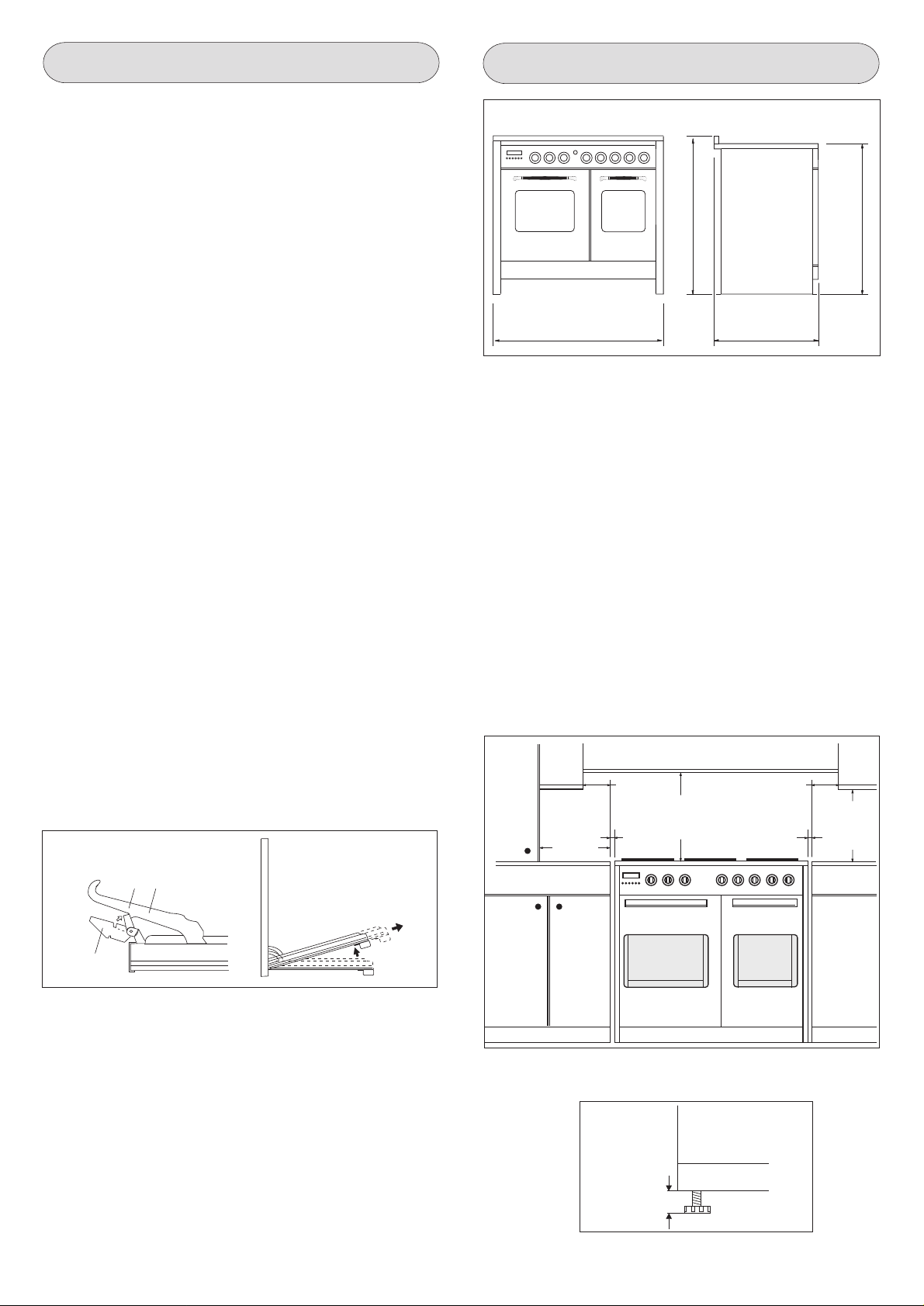
DIMENSIONI D’INGOMBRO
960
1000
600
AVVERTENZE
Prima di effettuare qualsiasi riparazione o intervento, staccare
la presa della corrente e chiudere il rubinetto del gas.
Il tecnico qualificato è responsabile della corretta installazione
secondo le norme di sicurezza vigenti.
La messa a terra dell'apparecchio è obbligatoria a termine di
legge.
Il costruttore declina ogni responsabilità per eventuali danni a
persone, animali o cose derivanti dalla mancata osservanza delle
norme sopra indicate. I dati tecnici sono indicati sulla targa matricola
situata nella parte interna del cassetto inferiore dell'apparecchio.
Le condizioni di regolazione sono riportate su un'etichetta applicata
sull'imballo. Non usare l’impugnatura della maniglia porta forno
per operazioni di movimentazione, compresa quella necessaria
per togliere l’apparecchiatura dall’imballo.
L’apparecchio è in classe 1 oppure classe 2 sotto-classe 1.
INSTALLAZIONE
IMPORTANTE: Il rivestimento del mobile deve essere di materiale
resistente al calore (minimo 90°C).
Se l'apparecchio deve essere installato vicino ai mobili, lasciare
gli spazi minimi previsti dal disegno seguente.
min. 50 mm min. 50 mm
min.100 mm
min. 20mm
min. 650 mm
min. 20mm
900
min. 400 mm
B C
A
FORNO
Per le parti smaltate pulire con una spugna inumidita in acqua e
sapone. Le macchie di grasso possono essere tolte facilmente
con acqua calda o con un prodotto specifico, reperibile in commercio per la pulizia dello smalto. Evitare i prodotti contenenti
sostanze abrasive.
La cucina è dotata di 4 piedini che servono per un eventuale
allineamento in altezza con i mobili (vedi fig. 8).
REG. MAX 15mm
Fig. 8
7
Page 8
IT
VENTILAZIONE LOCALI
APPARECCHI A GAS
Questo apparecchio non è collegato ad un dispositivo di scarico
dei prodotti della combustione. Deve quindi essere installato e
collegato conformemente alle norme di installazione vigenti.
Particolare attenzione sarà data alle norme applicabili in materia
di aerazione del locale.
VENTILAZIONE DEI LOCALI (UNI-CIG 7129-7131)
Ricordiamo che questo apparecchio può essere installato e
funzionare solo in locali ben ventilati, secondo le norme in vigore,
tali da permettere, con aperture su pareti esterne o con appositi
condotti, una corretta ventilazione naturale o forzata che assicuri
in modo permanente e sufficiente sia l'immissione dell'aria
necessaria ad una corretta combustione sia l'evacuazione dell'aria
viziata.
In particolare nel caso in cui nell'ambiente esista solo questo
apparecchio a gas, occorrerà avere una cappa sopra l'apparecchio
tale da assicurare l'evacuazione naturale e diretta dell'aria viziata,
con un condotto verticale rettilineo di lunghezza uguale ad almeno
due volte il diametro ed una sezione minima di almeno 100cm2.
Per l'indispensabile immissione di aria fresca nell'ambiente occorrerà
prevedere un'analoga apertura di almeno 100 cm2 che dia direttamente verso l'esterno, situata ad una quota prossima al livello
del pavimento in modo da non venire ostruita sia all'interno che
all'esterno della parete e da non provocare disturbi alla corretta
combustione dei bruciatori ed alla regolare evacuazione dell'aria
viziata e con una differenza di altezza rispetto all'apertura di uscita
di almeno 180 cm.
Si ricorda che la quantità d'aria necessaria alla combustione non
deve essere minore a 2m3/h per ogni kW di potenza (vedi potenza
totale in kW sulla targa matricola posta nella parte interna del
cassetto inferiore dell'apparecchio).
In tutti gli altri casi, quando cioè esistano nello stesso ambiente
altri apparecchi a gas, oppure quando non sia possibile avere una
ventilazione naturale diretta ed occorra invece realizzare una
ventilazione naturale indiretta od una ventilazione forzata è
necessario rivolgersi ad uno specialista qualificato in modo che
provveda all'installazione ed alla realizzazione eventuale
dell'impianto di ventilazione nell'osservanza scrupolosa delle
precauzioni contenute nelle norme in vigore.
Il posizionamento delle aperture deve essere tale che non risulti
alcuna corrente d'aria insopportabile per gli occupanti, inoltre per
lo scarico dei prodotti della combustione è vietato servirsi di canne
fumarie già utilizzate da altri apparecchi.
Nota: Quando l'apparecchio non è provvisto di sicurezza sui
bruciatori del piano di lavoro (termocoppie), le aperture di
ventilazione devono essere maggiorate nella misura del 100%
con un minimo di 200 cm2 in conformità al D.M.21 Aprile 1993.
COLLEGAMENTI GAS (UNI-CIG 7129-7131)
Si raccomanda di controllare che l'apparecchio sia predisposto
per il tipo di gas distribuito. Il collegamento alla tubazione del gas
deve essere effettuato a regola d'arte nonché conformemente alle
normative in vigore che prescrivono l'installazione di un rubinetto
di sicurezza all'estremità della tubazione. Per il butano ed il
propano, un riduttore di pressione conforme alle norme UNI-CIG
7432 può assolvere a questa funzione. Le guarnizioni di tenuta
devono essere conformi alle norme UNI-CIG 9264.
Terminate le operazioni di collegamento gas, controllare la tenuta
dei raccordi con acqua e sapone.
L'estremità dell'attacco è filettato.
I possibili collegamenti sono:
1) mediante tubo rigido in ferro o rame
2) mediante tubo flessibile in acciaio inossidabile a parete continua
con attacco meccanico conforme alle norme UNI-CIG 9891
(massima lunghezza del tubo esteso 2.000 mm).
Il tubo va collegato direttamente al gomito della rampa (vedi
fig.9).
1/2”
Fig. 9
3) mediante l'inserimento di un tubo di gomma conforme alle
norme UNI-CIG 7140. Tale tubo va innestato direttamente sul
portagomma, relativo al gas utilizzato, e bloccato con una
fascetta (F) conforme alle norme UNI-CIG 7141 (fig. 10).
In quest'ultimo caso controllare la data di scadenza del tubo
stampigliata e sostituirlo prima di tale data .
AVVERTENZE
Si ricorda per i tubi flessibili in gomma (max lunghezza
1500 mm), di:
1 - evitare strozzature o schiacciamenti del tubo
2 - non essere soggetti a sforzi di trazione e di torsione
3 - evitare contatti con corpi taglienti, spigoli vivi, ecc...
4 - non porli a contatto con parti che raggiungono temperature
maggiori di 70°C oltre a quella ambiente.
5 - renderli ispezionabili lungo tutto il loro percorso.
Fig. 10
min. 180 cm.
min. 180 cm.
elettroventilatore
min. 100cm2.
min. 100cm2.min. 100cm2.
PORTAGOMMA
PER GAS
LIQUIDO
F
F
PORTAGOMMA
PER GAS
METANO
Alcuni tipi di cucina possono essere predisposti per l’alimentazione
sia destra che da sinistra. Per effettuare lo spostamento d’alimentazione è sufficiente invertire la posizione del tappo di chiusura
e del raccordo. Ad operazione ultimata accertarsi che non vi siano
perdie di gas.
RACCORDOTAPPO DI CHIUSURA
8
Page 9
IT
COLLEGAMENTO ELETTRICO
L'allacciamento dell'apparecchio alla rete elettrica deve essere
effettuato da personale specializzato a conoscenza delle norme
di sicurezza vigenti.
La messa a terra dell'apparecchio è obbligatoria a termine di
legge. Prima di effettuare il collegamento elettrico, assicurar si
dell'efficienza della messa a terra.
Accertarsi che la valvola limitatrice e l'impianto domestico possano
sopportare il carico dell'apparecchiatura.
Deve essere previsto nella rete di alimentazione un dispositivo di
disconnessione con una distanza di apertura dei contatti che
consenta la disconnessione completa nelle condizioni della
categoria di sovratensione III, conformemente alle regole di
installazione.
Il cavo di terra giallo/verde non de ve essere interrotto dall'inter ruttore.
Importante: i fili del cavo hanno i seguenti colori:
- giallo/verde = per la messa a terra " " (E)
- blu = per il neutro "N"
- marrone = per la fase "L"
- Il cavo elettrico non deve essere a contatto con parti con
temperature maggiori di 50°C oltre a quella ambiente.
- Se si usa una spina per il collegamento, la spina da collegare
al cavo di alimentazione e la presa al quale viene collegato
dovranno essere dello stesso tipo (conformi alle norme).
REGOLAZIONI GAS
Se l'apparecchiatura risulta predisposta per un diverso tipo di gas
da quello di alimentazione disponibile, si devono cambiare gli
iniettori, regolare la portata minima, cambiare portagomma.
Per cambiare gli iniettori del piano di lav oro , è necessario effettuare
le seguenti operazioni: togliere le griglie; togliere i br uciator i, gli
spartifiamma (vedi fig.A); cambiare l'iniettore (vedi figura B) e
sostituirlo con quello adatto al nuovo tipo di gas (vedi tab.D).
Rimontare il tutto in senso inverso f acendo attenzione a collocare
lo spartifiamma in modo coretto sul bruciatore.
A B
Tipo di cavo d’alimentazione
Tipo di apparecchio Alimentazione monofase 230 V~
Tipo cavo Sezione
Piano gas con forno elettrico Gomma H05 RR-F 3 x 2,5 mm
2
SOSTITUZIONE DEL CAVO
In caso di danneggiamento del cavo, provvedere alla sua sostituzone secondo le seguenti istruzioni:
- aprire la scatola ella morsettiera come descritto in figura qui
sotto;
- svitare la vite “A” che blocca il cavo;
- sostituire il cavo con uno di lunghezza uguale e corrispondente
alle caratteristiche descritte in tabella;
- il conduttore di terra “giallo-verde” deve essere collegato al
morsetto “ “ e deve essere più lungo di circa 10 mm rispetto
ai conduttori di linea;
- il conduttore neutro “blu” deve essere collegato al morsetto
contraddistinto con la lettera “N”;
- il conduttore di linea va collegato al morsetto contraddistinto
con la lettera “L”.
TAB. D TABELLA GENERALE INIETTORI
Tipo di gas mbar Ugello Bruciatori Potenza Watt Consumo
mm/100 Posizione-tipo max. min. max.
115 Rapido 3000 750 286 l/h
METANO 20 97 Semi rapido 1750 480 167 l/h
128 Tripla corona 3300 1300 315 l/h
G.P.L. 30 85 Rapido 3000 750 219 g/h
BUTANO 28 65 Semi rapido 1750 480 128 g/h
PROPANO 37 93 Tripla corona 3300 1300 241 g/h
PORTATA MINIMA DEI RUBINETTI PIANO
Per regolare la portata minima procedere come segue:
- Accendere il bruciatore e girare la manopola verso la posizione
di portata minima ; togliere la manopola del rubinetto. Inserire
un cacciavite piccolo nell'asta del rubinetto (fig. 11).
Attenzione: nei rubinetti valvolati la vite di regolazione “Z” del
minimo si trova all'esterno dell'asta del rubinetto (fig. 12).
Z
1
L
3
2
Fig. 11
4
Fig. 12
Svitare la vite di regolazione per aumentare la portata, oppure
N
5
avvitare la vite per diminuire la portata. La regolazione è corretta
quando la fiamma misura circa 3 o 4 mm.
Per il gas butano/propano, la vite di regolazione deve essere
avvitata a fondo.
Assicurarsi che la fiamma non si spenga quando si passa bruscamente dalla portata massima , alla por tata minima e
viceversa.
Rimontare la manopola.
A
9
Page 10
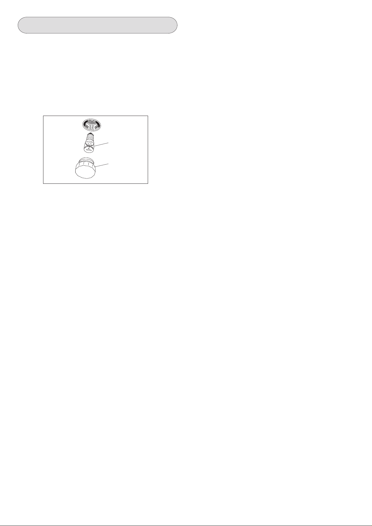
MANUTENZIONE APPARECCHIO
AVVERTENZE
Prima di effettuare qualsiasi riparazione o intervento, staccare
la presa della corrente e chiudere il rubinetto del gas.
Il costruttore declina ogni responsabilità per eventuali danni a
persone, animali o cose derivanti dalla mancata osservanza delle
norme sopra indicate.
La lampadina forno utilizzata è di tipo speciale resistente alle
alte temperature. Per sostituirla agire nel modo seguente: smontare
il vetro di protezione (A) e sostituire la lampada bruciata con una
dello stesso tipo, quindi rimontare il vetro.
E 14
25 W - 230 V~
T300°C
A
IT
INGRASSAGGIO DEI RUBINETTI
Se col passare del tempo i rubinetti del gas dovessero indurirsi
è necessaria una nuova lubrificazione con apposito lubrificante.
Tale operazione dovrà essere effettuata esclusivamente dal
Servizio Assistenza".
10
Page 11

GB
Securing the cooker to the wall
Drill two holes in the wall approximately 70 cm above the lower edge of the sides of the cooker (as shown in fig. A position
F, so that they are concealed by the cooker itself (see fig. B).
Insert part R (rawlplug) into holes F and screw hook G into part R (fig. C).
Secure the chain to hook G as shown in fig. D position C.
Fig. A
Fig. C
Position F = hole
ø 6 mm
60 mm +/- 3
86 cm +/- 5
H - adjustable
foot
Fig. B
Position
2
Fig. D
Position
chain
1
wall
wall
position C
G
R
F
11
Page 12

GB
GENERAL INFORMATION
DESTINED TO THE END USER
ENVIRONMENT PROTECTION
Packing disposal
Sort packing into different materials (cardboard, polystyrene
etc.) and dispose of them in accordance with local waste
disposal laws.
This appliance complies with the following European Directives:
- 73/23/EEC regarding "Low Voltage".
- 89/336/EEC regarding "Electromagnetic Disturbances".
- 90/396/EEC regarding “Gas appliances”
- 89/109/EEC regarding "Materials in contact with food"
- Moreover the abov e mentioned Directiv es comply with Directive
93/68/EEC.
- This household appliance has been designed for cooking and
it must therefore be used for this purpose only.
DEAR CUSTOMER,
• Carefully read these instructions before using the appliance and
keep them for future consultation.
• Keep potentially hazardous packaging (plastic bags , polystyrene
etc.) out of the reach of children.
CLIENT ASSISTANCE SERVICE
Before calling Technical Service
In case of malfunction, we advise you to:
- check that the plug is correctly inserted into the electricity supply;
- check that the gas is flowing normally.
If the cause of malfunction is not identified:
turn the apparatus off, do not tamper with it and call Technical
Service.
Before leaving the factory, this appliance has been tested and
set up by skilled personal, in order to give the best performance
results.
Each reparation or set up that could be necessary afterwards,
must be carried out with a great care and attention.
For this reason, we reccommend you to k eep alw a ys in touch with
the Sales Centre or with our nearer After Sales Service. Specify
always the kind of problem and the model of your appliance.
RECCOMANDATIONS AND PRECAUTIONS
ATTENTION:
- Before using the appliance, do not forget to remove the plastic
films protecting some parts of the appliance (facia-panel, parts
in stainless steel, etc.)
- Do not use the appliance as a space heater.
- When the appliance is not in use, we recommend to disconnect
the current and to close the gas general tap.
IN CASE OF FIRE:
• In case of fire, close immediately the main valve of the gas
pipe line, disconnect current and never pour water on firing
oil in any case.
• Do not store flammable products or aerosol containers near the
burners, and do not vaporize them near lighted burners.
FOR YOUR SAFETY AND THE ONE OF YOUR CHILDREN.
• Do not store items that are attractive to children above or near
the appliance.
• Keep children well away from the appliance: do not forget that
some parts of the appliance or of the pans become very hot and
dangerous during use, and also for all the time necessary to cool
down.
• In order to avoid any unintentional fall down, pan handles should
be turned to the back of the cooker, not out to the room or over
adjacent burners.
• When cooking, do not use clothes with large flaving and
flammable sleeves; in case of firing you can suffer very serious
harms.
WARNING - OVEN:
When the oven or the grill are in use, accessible parts can
become very hot; it is necessary to keep children well away
from the appliance.
- Never cook food on the lower wall of the oven.
- In case of careless use, in proximity of the oven door hinges,
there is hurt danger.
- Do not let children sit down or play with the oven door. Do not
use the drop down door as a stool to reach above cabinets.
WARMING CABINET
You must not place inflammable materials or plastic utensils in the
warming cabinet (placed below the oven).
12
Page 13

GB
WORK-TOP USE
USING GAS BURNERS
The following symbols are on the control panel ne xt to each knob:
- Black circle gas off
- Large flame maximum setting
- Small flame minimum setting
The minimum position is at the end of the anti-clockwise rotation
of the knob. All operation positions must be chosen between the
positions of max. and min., ne ver choose them between max. and
off.
The gas burners are equipped with a thermocouple safety device
to prevent gas from leaking out. This device ensures that the gas
supply is shut off if the flame on the gas burner is extinguished
while the burner is in use.
Igniting the gas burners
Proceed as follows to light one of the burners
• Turn the appropriate knob anti-clockwise to the large flame
symbol;
• Press in the knob firmly to activate the automatic gas
igniter ;
• Hold the knob in for around 10 seconds once the flame has
ignited to allow the thermocouple to heat up.
• Then release the control knob and ensure that the gas has
ignited properly. If it has not, repeat the process.
In case there is no electric current, the burner can also be lighted
using a match.
ENERGY SAVING TIPS
• The diameter of the pan bottom should be the same as that of
the burner. The burner flame must never come out from the pans
diameter.
• Use flat-bottomed pans only.
• Whenever possible, keep a lid on the pan while cooking.
You will not need as much heat.
• Cook vegetables, potatoes, etc. with as little water as possible
to reduce cooking times.
BURNERS PANS
Ø min. Ø max
RAPIDE 180 mm 220 mm
SEMIRAPIDE 120 mm 200 mm
TRIPLE CROWN 220 mm 260 mm
USE OF THE ELECTRIC OVEN
FIRST PART
The first time the oven is used, it may giv e off acrid smells, caused
by the first heating of isolating panels glue surrounding the oven
(it is necessary to heat up the oven at the maximum
temperature for about 30-40 minutes with closed door).
It is something normal, and in case it will occur, wait for the smok e
to stop before introducing the food into the oven.
The oven is fitted with: a rod shelf for cooking food contained in
oven dishes or placed directly on the rod shelf itself, a drip-tray
for cooking sweets, biscuits, pizzas, etc., or for collecting juices
and fats from food cooked directly on the rod shelf.
Note: The following tables give the main points for cooking some
of the most important dishes. The cooking times recommended
in these tables are approximate. After a few tries, we are sure that
you will be able to adjust the times to get the results you want.
Conventional cooking table TAB.B
Dish Temp. °C. Minutes
Fish 180-240 acc. to size
Meat
Roast ox 250 30 per kg.
Roast veal 200-220 30 per kg.
Chicken 200-240 50 about
Duck and goose 220 acc. to weight
Leg of mutton 250 30 per kg.
Roast pork 250 60 per kg.
Soufflets 200 60 per kg.
Sweets (pastries)
Tea-cake 160 50-60
Sponge finger 160 30-50
Shortcrust pastry 200 15
Puff pastry 250 15
Fruit flan 200-220 30
Meringues 100 60
Quiches, etc. 220 30
4 quarters 120-140 60
Buns 160-180 45
Fan oven cooking table TAB. C.
Dish Temp. °C. Minutes Weight kg.
Firs courses
Lasagne 200-220 20-25 0,5
Oven pasta 200-220 25-30 0,5
Creole rice 200-230 20-25 0,5
Pizza 210-230 30-45 0,5
Meat
Roast veal 160-180 65-90 1-1,2
Roast pork 160-170 70-100 1-1,2
Roast ox 170-190 40-60 1-1,2
Roast beef joint 170-180 65-90 1-1,2
Roast fillet beef (rare) 180-190 40-45 1-1,5
Roast lamb 140-160 100-130 1,5
Roast chicken 180 70-90 1-1,2
Roast duck 170-180 100-160 1,5-2
Roast goose 160-180 120-160 3-3,5
Roast turkey 160-170 160-240 5 approx.
Roast rabbit 160-170 80-100 2 approx.
Roast hare 170-180 30-50 2 approx.
Fish 160-180 acc. to weight
Sweets (pastries)
Fruit flan 180-200 40-50
Plain sandwich cake 160-180 35-45
Sponge sandwich cake 200-220 40-45
Sponge cake 200-230 25-35
Currant cake 230-250 30-40
Buns 170-180 40-60
Strûdel 160 25-35
Cream slices 180-200 20-30
Apple fritters 180-200 18-25
Sponge finger pudding 170-180 30-40
Sponge finder biscuits 150-180 50-60
Toasted sandwiches 230-250 7
Bread 200-220 40
13
Page 14
1 – NATURAL CONVECTION OVENS
The oven is fitted with:
• a lower heating element;
• an upper heating element.
It is possible to select the desired temperature into the oven by
turning clockwise the thermostat knob and depending on the
models, one or more functions:
Oven off
Oven light
60 ÷ max Upper + lower heating element on
Upper heating element on
Lower heating element on
Grill element on + turnspit
GB
ATTENTION:
The temperature shown on the control panel corresponds to the
temperature in the oven centre only when the functions selected
are or .
When you turn the control knob to this position, the light will be
on for all the following operations.
Defrosting with fan
The air at ambient temperature is distributed inside the oven for
defrosting food very quickly and without proteins adulterations.
Note:
Always use the oven with the oven door closed.
60
90
max
130
200
170
2 – MULTIFUNCTIONAL OVEN
Ovens with separate thermostat and commutator.
The oven is fitted with:
• a lower heating element;
• an upper heating element;
• a circular heating element surrounding the fan.
N.B.: Always set the temperature on the thermostat knob before
selecting any of the functions.
Oven thermostat knob
To obtain an oven temperature between 50°C and MAX°C, turn the
knob clockwise.
max
50
225
75
200
100
175
Oven commutator knob
Depending on the type of oven, it is possible to select one of the
following functions turning the commutator knob clockwise.
150
125
Natural convection
Both the lower and upper heating elements operate together.
This is the traditional cooking, very good for roasting joints, ideal
for biscuits, baked apples and crisping food.
You obtain very good results when cooking on a shelf adjusting
the temperature between 50 and MAX°C.
Fan oven
Both the fan and the circular heating element operate together.
The hot air adjustable between 50 and MAX°C is evenly distributed
inside the oven. This is ideal for cooking several types of food
(meat, fish) at the same time without affecting taste and smell.
It is indicated for delicate pastries.
Medium grill
It is indicated for grilling and gratinating small quantities of traditional
food.
The thermostat knob must be placed on the maximum position.
Total grill
It is indicated for grilling and gratinating traditional food.
The thermostat knob must be placed between 180 ÷ 200°C position
as maximum temperature.
Fan assisted total grill
The air which is heated by the grill heating element is circulated
by the fan which distributes the heat on the food.
The fan assisted grill replaces perfectly the turnspit. Y ou can obt ain
very good results also with large quantities of poultry, sausage,
red meat. The thermostat knob must be placed between 180 ÷
200°C position as maximum temperature.
Use of the oven
Note:
Always use the oven with the oven door closed.
When the functions are used, place the thermostat knob
between 180 ÷ 200°C as maximum temperature.
Air forced lower heating element
The air which is heated by the lower heating element is circulated
by the fan which distributes the heat on the food.
This function can be used to sterilize food. This function can be
used between 50 and MAX°C
Note:
All the functions mentioned above switch the oven internal light on.
A warning light on the control panel will stay lit until the temperature
is reached; after it will light up intermittently .
14
Page 15

USE OF THE GRILL
Install the grid on the third shelf from the oven bottom, at about
12 cm from the surface.
The user can change the shelves, depending on his personal
whishes and on the different food.
Geat the oven 5 minutes before introducing the food.
TURNSPIT
In order to make the electric heating element work follow the
instructions described in paragraph 1 page 5 position , this
selection puts into function the turnspit as well.
USE OF THE TURNSPIT
For utilization of the turnspit follow the instructions described.
- Put the food in spit L (see fig. 3), paying attention to block it
within the two forks F and to balance it, in order to avoid any
unnecessary effort in motor R (fig 3).
- Put the spit on support G, after having put its opposite end into
hole P of motor R.
- Place the drip-tray with a little water under the spit.
- To remote the spit, operate in the opposite direction using knob
A and protecting glove in isolating wool (see fig. 3).
R
P
2
GB
Setting the time
Press any two buttons manualat the same time, and or b utton
to set the desired time. This deletes an y previously set prog ramme .
The contacts are switched off .
Manual use
By pressing the manual button the relay contacts switch on, the
AUTO symbol switches off and the saucepan symbol lights up.
Manual operation can only be enabled after the automatic
programme is over or it has been cancelled.
Automatic use
Press the cooking time or end time button to switch automatically
from the manual to the automatic function.
Semi-automatic use with cooking time setting
Press the cooking time button and set the desired time with or
. The AUTO and cooking time symbols light up continuously.
The relay switches on immediately. When the cooking end time
corresponds to the time of day, the relay and cooking time symbol
switch off, the sound signal rings and the AUTO symbol flashes.
Semi-automatic use with end time setting
Press the end time button. The time of day appears on the display .
Set the cooking end time with button. The AUTO and cooking
time symbols light up continuously. The rela y contacts switch on.
When the cooking end time corresponds to the time of day, the
relay and the cooking time symbol switch off. When the cooking
time is up, the AUTO symbol flashes, the sound signal rings and
both the relay and the cooking time button switch off.
G
1
Fig. 3
F
L
A
1
INSTRUCTIONS FOR USE OF CONTROL DEVICES
“LED” PROGRAMMER (Fig. 4)
Features
24 hours clock with automatic programme and minutes counter.
Functions
Cooking time, cooking end time, manual position, clock,
minutes counter, times to be set up to 23 hours 59 minutes.
Display
4-figures, 7-segments diplay for cooking times and time of day.
Cooking time and manual function = saucepan symbol
Automatic function = AUTO
Minutes counter = bell symbol
The symbols light up when the corresponding functions are
selected.
Minute timer
A
U
T
O
Fig. 4
Setting
To set, press and release the desired function, and within 5
seconds set the time with and buttons.
and buttons.
The + and - buttons increase or decrease the time at a speed
depending on how long the button is pressed.
Cooking time
Cooking end
Manual
Subtract time
Add time
Automatic use with cooking time and end time setting
Press the cooking time button and select the length of the cooking
time with or button. The AUTO and cooking time symbols
light up continuously. The relay switches on. By pressing the
cooking end time button the next cooking end time appears on
the display. Set the cooking end time with button. The rela y and
the cooking time symbol switch off.
The symbol lights up again when the time of day corresponds to
the cooking start time. When the cooking time is up, the AUTO
symbol flashes, the sound signal rings, the cooking time symbol
and the relay switch off.
Minutes counter
Press the minutes counter button and set the cooking time with
or button.
The bell symbol lights up when the minutes counter is operating
When the set time is up, the sound signal rings and the bell symbol
switches off.
Sound signal
The sound signal starts at the end of a programme or of the
minutes counter function and it lasts for 15 minutes.
To stop it, push any one of the functions buttons.
Start programme and check
The programme starts 4 seconds after it has been set.
The programme can be checked at any time by pressing the
corresponding button.
Setting error
A setting error is made if the time of day on the clock falls within
the cooking start and end times.
To correct the setting error, change the cooking time or cooking
end time.
The relays switch off when a setting error is made.
Cancelling a setting
To cancel a setting, press the cooking time button and then press
the - button until 00 00 appears on the display.
A set programme will automatically cancel on completion.
15
Page 16

GB
CARE AND MAINTENANCE
Before cleaning the appliance, disconnect the gas general
tap and unplug the appliance or disconnect power at the
main circuit breaker of the electrical system.
Do not clean the appliance surfaces when still hot.
IMPORTANT
Periodically check the external gas connection hole and
replace it when it shows any sign of deterioration. Do not
attempt to repair the gas hose under any cincumstances.
ENAMELLED SURFACES
Clean with a damp sponge using soap and water.
Grease can be easily removed using hot water or a specific
cleansing agent for enamelled surfaces. Do not use abrasive
cleansers.
Do not leave any acid or alkaline substances (lemon juice , vinegar ,
salt, etc.) on the enamel.
Clean the parts in stainless steel with specific cleansers for
stainless steel surfaces.
These detergents must be applied using a soft cloth.
GRIDS AND BURNERS
To clean the work-top burners, remove them by pulling upwards
and soak them for about 10 minutes in hot water with a little
detergent. After having cleaned and washed them, wipe them
carefully.
Make sure that no burner hole is clogged.
Clean the burners once a week or more frequently if necessary.
MAKE SURE YOU HAVE ASSEMBLED THE BURNERS IN A
RIGHT WAY.
INSTRUCTIONS DESTINED TO THE USER
OVERALL DIMENSIONS
960
1000
600
WARNINGS
The technical data are indicated on the data nameplate placed
on the inside of the front appliance drawer .
The adjustment conditions are stated on the label applied on the
packaging and on the appliance.
Do not use the oven door handle to move the appliance, such as
to remove it from the packaging.
The appliance is in class 1 or class 2 subclass 1.
INSTALLATION
IMPORT ANT : The coating of the furniture must be ab le to withstand
high temperatures (min. 90°C).
If the appliance is to be installed near units, leave the minimum
gaps specified in the table below.
900
OVEN DOOR
For some models, the oven door can be disassembled in the
following way:
hinges A are provided, for this purpose, with two mov ab le jumpers
B; these, once hooked to the hinges slots C, when the door is
completely opened, block them. After that lift the door outward
carring out the two movements shown in the picture. To do that,
operate on the door sides next to the hinges. In order to reassemble the door, introduce the hinges in their relevant slots.
Before closing the door, do not forget to remove the movable
jumpers B.
Attention, in proximity of the oven door hinges , there is hurt danger.
B C
A
min. 50 mm min. 50 mm
min.100 mm
min. 20mm
min. 650 mm
min. 20mm
min. 400 mm
The cooker is fitted with 4 legs for an e v entual alignment in height
with the furniture ( fig 8).
OVEN
Clean the enamelled parts with a damp sponge using soap and
water. Grease can be easily removed using hot water or a specific
cleansing agent for enamelled surfaces.
Do not use abrasive cleansers.
REG. MAX 15mm
Fig. 8
16
Page 17

GAS CONNECTING
This appliance shall be installed in accordance whit the regulations
in force and only in a well-ventilated space. Read the instructions
before installing or using this appliance.
IMPORTANT
This cooker is supplied for use on Natural Gas Only and cannot
be used for any other gas without modification.
Conversion for use on LPG and other gases must only be
undertaken by a qualified person. For information for use on other
gases contact your local Service Centre.
The cooker must be installed by a qualified person in accordance
with the Gas Safety (Installation and Use) (Amendment) Regulations
1990 and the relevant building/I.E.E. Regulations.
Failure to install the appliance correctly could invalidate any
manufacturers warranty and lead to prosecution under the above
quoted regulations.
Provision for Ventilation
The room containing the cooker should have an air supply in
accordance with BS 5440: Part 2: 1989. The room must have an
opening windows or equivalent; some rooms may also require a
permanent vent. If the room has a volume between 5 and 10m 3,
it will require an air vent of 50cm2 effective area unless it has a
door which opens directly to the outside. If the room has a v olume
of less than 5m3, it will require an air vent of 100cm2 effective
area. If there are other fuel b urning appliances in the same room,
BS 5440: Part 2: 1989 should be consulted to determine air vent
requirements. Ensure that the room containing the cooker is well
ventilated, keep natural ventilation holes or install a mechanical
ventilation device (mechanical cook er hood). Prolonged intensive
use of the appliance may call for additional v entilation, f or example
opening of a window, or more effective ventilation, for example
increasing the level of mechanical v entilation where present. This
cooker is not fitted with a device for discharging the products of
combustion. Ensure that the ventilation rules and regulations are
followed. Excess steam from the oven, vents out at the top back
edge of the cooker, so make sure that the walls behind and near
the cooker are resistant to heat, steam and condensation. Your
cooker must stand on a flat surface so that when it is in position
the hob is level. When in position check that the cooker is lev el by
using a spirit level and adjust the 2 feet at the rear and the 2 feet
at the front if necessary. It is impor tant that the cooker is stable
and level for the overall cooking performance.
Remember that the quantity of air necessary for combustion must
never be less than 2m3/h for each kW of power (see total power
in kW on the appliance data plate placed on the drawer).
Gas Safety (Installation & Use) Regulations
It is the law that all gas appliances are installed by competent
persons in accordance with the current edition of the Installation
& Use Regulations. It is in your interest and that of safety to
ensure compliance with the law.
In the UK, CORGI registered installers work to safe standards of
practice.
The cooker must also be installed in accordance with BS 6172:
1990.
Failure to install the cooker correctly could invalidate the warranty
liability claims and could lead to prosecution.
GB
Gas Connection
Prior to installation, ensure that the local distribution conditions
(nature of the gas and gas pressure) and the adjustment conditions
are compatible. The adjustment conditions for this appliance are
stated on the rating plate which can be found on the inside of
the front appliance drawer .
This appliance is not designed to be connected to a combustion
products evacuation device. Particular attention should be given
to the relevant requirements regarding ventilation.
Connection to the cooker should be made with an approved
appliance flexible connection to BS 669. Models for use with LPG
should be fitted with a hose suitable for LPG and capable of
withstanding 50mbar pressure. A length of 0.9 to 1.25m is
recommended. The length of hose chosen should be such that
when the cooker is in situ, the hose does not touch the floor.
The temperature rise of areas at the rear of the cooker that are
likely to come in contact with the flexible hose do not exceed 700C.
Gas pressure may be checked on a semi-r apid hob burner . Remov e
the appropriate injector and attach a test nipple. Light the other
burners and observe that the gas pressure complies with the gas
standards in force.
Certain types of cookers can be set for sypply both on the right
and lefthand side. In this case it is sufficient to re v erse the position
of the cad nipple reducer. At the end make sure than there is no
leakage of gas.
STOP
INLET
ELECTRICAL CONNECTION
This appliance must be installed by a qualified person in
accordance with the latest edition of the IEE Regulations and
in compliance with the manufacturer instructions.
Ensure that the voltage is the same as that stated on the rating
plate. The rating plate which can be found on the inside of the
front appliance drawer.
WARNING! THIS APPLIANCE MUST BE EARTHED
The power supply must be fitted with a disconnect switch in which
the distance between contacts permits total disconnection in
accordance with overvoltage category III, as required by installation
regulations.
Be sure that the earth wire green/yellow is not interrupted
by the switch
We recommend that the cooker circuit is rated to 13 amps.
Cable type HO5 RRF 3 X 2.5 mm
Connecting the mains cable
Open the mains terminal block cover as shown, unscrew screw
“A” the cable clamp and unscrew (not fully) the screws in the
mains terminal block “L N E” which secure the three wires of the
mains cable. Fit the cable and refit screw “A” the cable clamp.
Allow sufficient cable length for the cooker to be pulled out for
cleaning, but do not let it hang closer than 50mm (2”) to the floor.
The cable can be looped if necessary, but make sure that it is not
kinked or trapped when the cooker is in position.
17
2
Page 18

GB
TAB. D GENERAL INJECTORS TABLE
Kind of gas mbar Nozzle Burners Power Watt Consum.
L
N
1
2
3
4
5
NATURAL 20 97 -Semi rapide 1750 480 167 l/h
G.P.L. 30 85 -Rapide 3000 750 219 g/h
BUTANE 28 65 -Semi rapide 1750 480 128 g/h
PROPANE 37 93 -Triple crown 3300 1300 241 g/h
mm/100 Posizione-type max. min. max.
115 -Rapide 3000 750 286 l/h
128 -Triple crown 3300 1300 315 l/h
A
IMPORTANT
The wires in the mains lead are coloured in accordance with the
following code:
GREEN AND YELLOW......EARTH
BLUE.................................NEUTRAL
BROWN.............................LIVE
REPLACEMENT OF THE CABLE
In case the cable is damaged, replace it in accordance with the
following instructions:
- open the box of the supply board as described on the picture
below;
- unscrew screw “A” fixing the cable;
- replace the cab le with one of the same lenght and in accordance
with the features described on the table; switch the appliance
off, and close the gas tap
- the ‘green-yellow” earth wire must be connected to the terminal
“ “ and it must be about 10 mm longer thean the live wires;
- the “blue” neutr al wire must be connected to the terminal marked
with letter “N”;
- the live wire must be connected to the terminal marked with letter
“L”.
MINIMUM FLOW ADJUSTMENT FOR WORK-TOP TAPS
In order to adjust the minimum, act as follows: switch the burner
on, and turn the knob towards the minimum flow position .
Remove the knob from the tap , introduce a little scre wdriver in the
tap rod (fig. 11).
Attention: in taps with security valv e , the minimum adjusting scre w
“Z” is placed outside the rod tap (fig. 12).
Z
Fig. 11
Fig. 12
Unscrew the adjusting screw in order to increase the flow or scre w
it to decrease the flow.
The right adjustment is obtained when the flame has a length of
about 3 or 4 mm.
For butane/propane gas, the adjusting scre w must be tight screw ed.
Make sure that the flame does not go out passing quickly from
the max. flow to the minimum flow .
Assemble the knob again.
GAS ADJUSTMENT
Conversion to LPG
Always isolate the cooker from the electricity supply, turn off the
gas supply temporarily and proceed as follows.
- change the injectors,
- adjust the minimum flow of the burners.
REPLACEMENT OF WORK-TOP INJECTORS
In order to change the work-top injectors, it is necessary to act as
follows: remove the grids, remove burners and flame-spreaders
(see fig.A), change the injector (see fig.B) and replace it with
another one suitable for the new type of gas (see table D). Reassemble ev erything in the opposite direction, paying attention to
place the flame-spreader in the right way on the burner.
A B
APPLIANCE MAINTENANCE
WARNINGS
Isolate the cooker from the electricity supply before attempting to
replace the oven lamp.
The oven lamp used is of a special type withstanding high
temperatures. To replace it, act as follows: disassemble the
protecting glass (A) and replace the burnt lamp with one of the
same type. Reassemble the protecting glass.
E 14
25 W - 230 V~
T300°C
A
18
Page 19

GAS TAP LUBRICATION
If the hob’s gas control knobs become stiff over time, they should
be lubricated with an appropriate lubricant. This must be carried
out by a Technical Service only.
GB
For your safety
The product should only be used for its intended purpose which
is for the cooking of domestic foodstuffs.
Under no circumstances should any external covers be removed
for servicing or maintenance except by suitably qualified personnel.
Do’s and Do Not’s
Do make sure you understand the controls before using the
cooker.
Do check that all controls on the cooker are turned off after use.
Do always stand back when opening an oven door to allow heat
to disperse.
Do always use dry, good quality oven gloves when removing
items from the oven.
Do take care when removing items from the oven, as the contents
may be hot.
Do always keep the oven doors closed when the cooker is not
in use.
Do always place pans centrally over the hob burners and position
them so that the handles cannot accidentally be caught or knocked
or become heated by other burners.
Do keep the cooker clean, as a build up of grease or fat from
cooking can cause a fire.
Do always allow the cooker to cool before cleaning.
Do always follow the basic principles of food handling and hygiene
to prevent the possibility of bacterial growth.
Do always keep ventilation slots clear of obstructions.
Do always turn off the electricity before cleaning or replacing an
oven lamp.
Do always use a CORGI registered engineer for servicing.
Do not allow children near the cooker when in use as all surfaces
will become hot during and after cooking.
Do not allow anyone to sit or stand on any part of the cooker.
Do not heat up unopened food containers as pressure can build
up causing the container to burst.
Do not store chemicals , food stuffs, pressurised containers in or
on the cooker, or in cabinets immediately above or next to the
cooker.
Do not fill a deep fat frying pan more than1/3 full of fat, oil, or use
a lid.
DO NOT LEAVE UNATTENDED WHILE COOKING.
Do not place flammable or plastic items on or near the hob
burners.
Do not use proprietary spillage collectors on the hob burners.
Do not use the cooker as a room heater.
Do not dry clothes or place other items over or near to the hob
burners or oven doors.
Do not wear garments with long flowing sleeves whilst cooking.
Do not place inflammable materials in the oven or the compartment
below the oven.
Do not allow fat or oil to build up in the oven trays, grill pan or
oven base.
Do not place cooking utensils or plates onto the oven base.
Do not grill food containing fat without using the grid.
Do not cover the grilling grid with aluminium foil.
Do not place hot enamel parts in water, leave them to cool first.
Do not allow vinegar, coffee, milk, saltwater, lemon or tomato
juice to remain in contact with enamel parts (inside the oven and
oven trays).
Do not use abrasive cleaners or powders that will scratch the
surface of the stainless steel and the enamel.
19
Page 20

FR
Comment fixer la cuisinière au mur.
Percez deux trous dans le mur, à environ 70 cm au-dessus du bord inférieur des côtés de la cuisinière (comme illustré dans
le fig. A position F), de façon à ce qu'ils soient cachés par celle-ci (voir fig. B).
Introduisez l' élément R (cheville en plastique) dans les orifices F et vissez le crochet G dans l' élément R (fig. C).
Fixez la chaîne au crochet G comme illustré dans la fig. D position C.
Fig. A
Fig. C
Position F = orifice
de ø 6 mm
60 mm +/- 3
86 cm +/- 5
H - pied
réglable
Fig. B
Position
2
Fig. D
Position
chaine
1
Mur
Mur
position C
G
R
F
20
Page 21

FR
RENSEIGNEMENTS GENERAUX
DESTINES A L’UTILISATEUR
AVERTISSEMENTS POUR L'ENVIRONNEMENT
Déchets emballage
Ne pas jeter l'emballage de Votre appareil aux ordures, mais
sélectionnez les différents matériaux (par ex. tôle, carton,
polystyrène) selon les prescriptions locales pour l'élimination
des déchets.
Ce produit répond aux éxigences des Directives Communautaires:
- 73/23/CEE relative à la "basse tension".
- 89/336/CEE relative aux "per turbations électromagnétiques".
- 90/396/CEE relative aux “appareils à gaz”
- 89/109/CEE relative aux “matériaux en contact avec les aliments".
- En plus les Directives sur mentionnées sont conformes à la
Directive 93/68/CEE.
- Cet appareil devra être exclusivement destiné à l'usage pour
lequel il a été expressément projeté, en tant “qu'appareil de
cuisson” domestique.
CHER CLIENT,
• Nous Vous invitons à lire attentivement ces instructions avant
d'utiliser l'appareil et de les conserver soigneusement afin de
les consulter en cas de besoin.
• Le matériel d'emballage (sacs en plastique, morceaux de
polystyrène, etc...) doit être tenu hors de portée des enfants
car il constitue une source potentielle de danger.
CONSEILS ET AVERTISSEMENTS
D’ORDRE GENERAL
ATTENTION:
- N'oubliez pas, avant d'utiliser l'appareil, d'enlever le film de
plastique qui protège certaines pièces (tableau de bord, cadres
en inox, etc).
- Ne pas utiliser l'appareil pour chauffer la pièce.
- Lorsque l'appareil n'est pas utilisé, débrancher le courant et
fermer le robinet général du gaz.
EN CAS D'INCENDIE
• En cas d'incendie, fermer le robinet général d'alimentation
et couper le courant; ne jamais jeter de l'eau sur l'huile en
flamme ou en train de frire.
• Ne pas garder de produits infammables ou de bouteilles d'aérosol
près de l'appareil et ne pas vaporiser d'aérosol près d'un brûleur
allumé.
POUR VOTRE SURETE ET CELLE DE VOS ENFANTS.
• Eviter de garder dessus ou près de l'appareil des produits
attractifs pour les enfants.
• Garder les enfants loin de l'appareil: ne pas oublier que certaines
parties de l'appareil ou des casseroles utilisées deviennent très
chaudes et dangereuses tant pendant le fonctionnement que
pendant le temps nécessaire au refroidissement après l'extinction.
• Faire attention aux poignées des casseroles, disposez-les de
façon que les jeunes enfants ne fassent pas tomber les
casseroles.
• Ne mettez pas de vêtements ou d'accessoires amples lorsque
les brûleurs sont allumés; l'incendie du textile peut être cause
de graves blessures.
SERVICE CLIENTS
Avant d’appeler le Service d’Assistance Technique
En cas de non fonctionnement de l’appareil, il est conseillé de:
— vérifier que l’appareil soit bien branché à la prise de courant,
— vérifier que le flux de gaz soit régulier.
Si la cause du mal fonctionnement n'est pas détectée:
éteindre l’appareil, ne pas le manipuler et appeler le Service
d’Assistance Technique
Cet appareil, avant de sortir de l’usine, a été essayé et réglé par
du personnel expert et spécialisé, afin de pouvoir donner les
meilleurs résultats de fonctionnement.
Toute réparation ou mise au point, qui pourrait ensuite se rendre
nécessaire, doit être effectuée av ec le plus gr and soin et beaucoup
d’attention.
Pour cette raison, nous conseillons de Vous adresser toujours au
revendeur ou à notre Centre Assistance plus proche, en spécifiant
le type d’incovénient et le modèle de Votre appareil.
ATTENTION - FOUR:
Lorsque le four ou le grilloir sont en fonction, les parties
accessibles peuvent devenir très chaudes, il faut éloigner les
jeunes enfants de l'appareil.
- Eviter de cuire les aliments sur la base du four.
- En cas d'utilisation négligente en proximité des charnières de
la porte du four, il existe le danger de se blesser les mains.
- Interdir aux enfants de s’asseoir ou de jouer avec la porte du
four. Ne pas utiliser la porte comme un tabouret.
TIROIR INFERIEUR
N’introduisez pas de matériaux inflammables ou en plastique
dans le chauffe-plats (positionné au dessous du four).
21
Page 22

FR
UTILISATION DE LA TABLE DE TRAVAIL
UTILISATION DES BRULEURS A GAZ
Les symboles suivants se trouvent sur le bandeau de commande,
près de chaque bouton:
- Disque plein robinet fermé
- Grande flamme ouverture maximale
- Petite flamme ouverture minimale
La position de minimum se trouve à la fin de la rotation en sens
inverse des aiguilles d'un montre de la manette.
Toutes les positions de fonctionnement doivent être choisies entre
les positions de max. et de min., jamais entre max. et la fermeture.
Les brûleurs sont équipés d’une protection thermoélectrique
contre l’échappement de gas. Ce mécanisme coupe l’arrivée de
gaz lorsque la flamme du brûleur s’éteint en cours de cuisson.
Allumage des brûleurs
Pour allumer un brûleur, procédez comme suit :
• tournez la manette correspondante dans
le sens contraire des aiguilles d’une montre de manière à la
positionner sur le symbole de la grande flamme;
• enfoncez complètement la manette pour faire fonctionner
l’allumage automatique du brûleur ;
• lorsque la flamme brûle, maintenez env. 10 secondes la manette
enfoncée, afin de permettre le chauffement du thermocouple.
• lâchez ensuite la manette et vérifiez que la flamme est stable.
Si ce n’est pas le cas, répétez l’opération.
ECONOMIE D'ENERGIE
• Le diamètre du fond de la casserole doit correspondre au diamètre
du brûleur. La flamme du brûleur ne doit jamais sortir du diamètre
de la casserole.
• Utiliser toujours des casseroles à fond plat.
• Cuire de préférence avec un couvercle. Cela permet d'utiliser
des puissances plus basses.
• Cuire les légumes, pommes de terre, etc. avec peu d'eau pour
économiser l'énergie et réduire les temps de cuisson.
Fig.1
BrÛleurs Ø min Ø max
-Rapide 180mm 220mm
-Semirapide 120mm 200mm
-Triple couron 220mm 260mm
UTILISATION DU FOUR ELECTRIQUE
PREMIERE PARTIE
Quand le four est utilisé pour la première fois , il peut se produire
de la fumée de odeur âcre, causée par le premier chauffage du
collant des panneaux isolants autour du four (il est opportun de
le chauffer à la température maximale pour une durée de 3040 minutes à porte fermée). Il s’agit d’un phénomène absoluement
normal et, s’il devait se produire encore, il faudrait attendre que
la fumée cesse avant d’introduire les aliments.
En général le four est équipé de: grille support pour la cuisson
des préparations en casseroles ou bien posées directement sur
la grille, lèche-frite pour la cuisson des gâteaux, biscuits, etc. ou
pour récupérer les jus et les matières grasses des aliments placés
directement sur la grille.
Note: dans les tableaux suivants il y a les indications pour la
cuisson de quelques préparations principales. Les temps de
cuisson conseillés dans ces tableaux sont indicatifs. Nous sommes
sûrs qu’après quelque essais vous pourrez apporter les
modifications nécessaires pour obtenir les résultats désirés.
Tableau de cuisson système traditionnel TAB. B
Preparations Temp. °C. Minutes
Poisson 180-240 suivant dim.
Viande
Rôti de boeuf 250 30 par kg.
Rôti de veau 200-220 60 par kg.
Poulet 200-240 env. 50
Canard ou oie 220 suivant poids.
Gigot de mouton 250 30 par kg.
Rôti de porc 250 60 par kg.
Soufflés 200 60 par kg.
Gateaux
Cake 160 50-60
Biscuits de Savoie 160 30-50
Pâte brisée 200 15
Pâte feuilletée 250 15
Tarte aux fruits 200-220 30
Meringues 100 60
Gratin 220 30
Cake 4/4 120-140 60
Brioches 160-180 45
Tableau de cuisson à air chaud TAB. C.
Préparations Temp. °C. Minutes Poids kg.
Entrées
Lasagnes au four 200-220 20-25 0,5
Pâtes au four 200-220 25-30 0,5
Riz à la créole 200-230 20-25 0,5
Pizza 210-230 30-45 0,5
Viandes
Rôti de veau 160-180 65-90 1-1,2
Rôti de porc 160-170 70-100 1-1,2
Rôti de boeuf 170-190 40-60 1-1,2
Filet de boeuf 170-180 35-45 1-1,5
Roast-Beef 180-190 40-45 1-1,5
Rôti d’agneau 140-160 100-130 1,5
Poulet rôti 180 70-90 1-1,2
Canard rôti 170-180 100-160 1,5-2
Oie rôti 160-180 120-160 3-3,5
Dindon rôti 160-170 160-240 5 env.
Lapin rôti 160-170 80-100 2 env.
Lievre rôti 170-180 30-50 2 env.
Poisson 160-180 d’après poids
Gâteaux (Pâtisserie)
Tarte aux fruits 180-200 40-50
Savarin 160-180 35-45
Gâteau “Margherita” 200-220 40-45
Pain de Genes 200-230 25-35
Fouace au raisin 230-250 30-40
Brioches 170-180 40-60
Strûdel 160 25-35
Feuillantines sucrèes 180-200 20-30
Beignets de pom. 180-200 18-25
Flan biscuit Savoie 170-180 30-40
Biscuits de Savoie 150-180 50-60
Toasts 230-250 7
Pain 200-220 40
22
Page 23

1 – FOURS A CONVECTION NATURELLE (Petit four)
Le four est pourvu de:
• une résistance inférieure;
• une résistance supérieure.
It is possible to select the desired temperature into the oven by
turning clockwise the thermostat knob and depending on the
models, one or more functions:
Four éteint
Lumière four
60 ÷ MAX Branchement de la résistance supérieure + inférieure
Branchement de la résistance supérieure
Branchement de la résistance inférieure
Branchement du grilloir + tournebroche
Note:
Un témoin placé sur le tableau de bord reste allumé jusqu’à ce
que la température soit atteinte, ensuite il s’allumera par
intermittence.
Le four toujours doit être a la porte fermée.
60
90
max
130
200
170
2 – FOUR MULTIFONCTION (Grand four)
Le four est pourvu de:
• une résistance inférieure;
• une résistance supérieure;
• une résistance circulaire qui entoure le ventilateur.
N.B.: Le branchement de n’importe quelle fonction a lieu toujours
après avoir placé la manette du thermostat en correspondance
de la température désirée.
Thermostat four
Tourner la manette dans le sens des aiguilles d'une montre pour
sélectionner la température du four désirée, comprise entre 50
et MAX°C
max
50
225
75
200
100
175
Sélecteur fonctions four
Tourner la manette des le sens des aiguilles d'une montre pour
sélectionner la fonction du four désirée
150
125
FR
Note:
Un témoin placé sur le tableau de bord reste allumé jusqu’à ce
que la température soit atteinte, ensuite il s’allumera par
intermittence. Le four toujours doit être a la porte fermée.
Utilisation du four
Note: fours avec thermostat et commutateur séparés.
Lorsqu’on utilise les fonctions placer la manette du
thermostat entre 180 ÷ 200°C comme température maximale.
ATTENTION:
La température indiquée sur le tableau de bord correspond à la
température maintenue au centre du four seulement quand les
fonctions sélectionnées sont ou .
Une fois tourné le bouton sur cette position, la lampe reste allumée
pendant toutes les opérations qui suivent.
Décongélation par ventilateur
Cette position permet la circulation de l’air pulsé à la température
ambiante tout autour de l’aliment surgelé en le décongelant sans
modifier ou altérer son contenu protéique. La manette du thermostat
doit être placée sur la position maximale.
Convection naturelle
Branchement de la résistance inférieure et supérieure du four. Il
s’agit de la cuisson traditionnelle, excellente pour rôtir les gigots,
idéale pour les biscuits, les pommes au four et pour que les
aliments deviennent très croquants. On obtient de bons résultats
pour les cuissons sur un niveau avec réglage de la température
de 50 à MAX°C.
Cuisson par air pulsé
La résistance circulaire et le ventilateur sont en fonction. L’air
chaud, réglable entre 50 et MAX°C, est poussé uniformément sur
tous les étages du four. Ceci permet une cuisson idéale de plusieurs
mets ensemble (viande, poisson, etc.) sans mélanger les différents
odeurs et saveurs. Cuisson délicate indiquée pour Génoises,
gâteaux de Savoie, pâtes feuilletées, etc.
Gril moyen
Par cette position, la résistance du gril moyen à l’infrarouge est
en fonction. Ceci permet de griller ou gratiner les plats traditionnels
de petites dimensions.
Gril
Par cette position, la résistance du gril à l’infrarouge est en fonction.
Ceci permet de griller ou gratiner les plats traditionnels.La manette
du thermostat doit être placée sur la position 180-200°C.
Grill ventilé
L’air, chauffé p ar la résistance du gril, est aspiré par le ventilateur
et poussé sur les aliments. Le gril ventilé remplace remarquablement
le tournebroche et il assure des résultats excellents avec volailles,
saucisses et viandes rouges, même en quantité considérable.La
manette du thermostat doit être placée sur la position 180-200°C.
Note:
Un témoin placé sur le tableau de bord reste allumé jusqu’à ce
que la température soit atteinte, ensuite il s’allumera par
intermittence.
Sole ventilé
L’air, réchauffé par la résistance inférieure, est aspiré par le
ventilateur et poussé sur les aliments. Cette fonction peut être
utilisée pour stériliser les aliments. Cette fonction peut être utilisée
entre 50 et MAX°C.
23
Page 24

FR
UTILISATION DU GRILLOIR
Positionner la grille porte-plats au troisième gradin en partant du
fond du four, à 12 cm à peu près de la surface rayonnante.
Vous pouvez changer de gradin, suivant votre goût personnel et
les nécessités des différents mets. Avant d’enfourner, laisser
chauffer 5 minutes.
Tournebroche
Pour la mise en fonction du tournebroche, tourner la manette sur
le symbole .
- Enfiler le poulet ou la pièce à rôtir sur la broche L en prenant
bien soin de l’immobiliser entre les deux fourches F et de bien
l’équilibrer afin d’éviter des efforts inutiles au moto-réducteur R.
(fig. 3).
- Mettre la broche sur le support G, après avoir introduit son
extrémité opposée dans le trou P du moteur R (fig. 3).
- Engager la lèchefrite avec un peu d’eau au dessous de la broche.
- Pour enlever la broche opérer de la façon contraire utilisant la
manette A et un guant de protection en laine isolante (fig.3).
R
P
2
G
1
Fig. 3
F
L
A
1
INSTRUCTIONS POUR L’UTILISATION DES
DISPOSITIFS CONTROLE
HORLOGE “LED” (Fig. 4)
Caractéristiques
Horloge 24 heures avec programmation automatique et compteminutes.
Fonctions
Durée de cuisson, fin cuisson, position manuelle, horloge, compteminutes, temps réglables jusqu’à 23 heures et 59 minutes.
Affichage des fonctions
Affichage lumineux à 4 chiffres de 7 segments pour indiquer l’heure
et les temps de cuisson.
Durée de cuisson et fonction manuelle = symbole de la casserole
Fonction automatique = AUTO
Compte-minutes = symbole de la cloche
Une fonction est sélectionnée lorsque le symbole correspondant
est affiché.
Minuterie sonore
A
U
T
O
Fig. 4
Programmation
La programmation s’effectue en appuyant sur le bouton de la
fonction désirée. Après avoir relâché ce bouton, il est suffisant de
programmer le temps avec et entre 5 secondes.
Boutons et
En appuyant sur les boutons et le temps augmente ou diminue
à une vitesse variable selon la durée de la pression sur le bouton.
Durée de cuisson
Fin de cuisson
Manuel
Diminution du temps
Augmentation du temps
Réglage de l’heure
Pour régler l’heure désirée, appuyer en même temps sur les deux
boutons manual et ou . Par cette opération, tous programmes
précédents sont éliminés, les contacts sont débranchés.
Fonctionnement en manuel
En appuyant sur le bouton de manuel, les contacts du relais se
branchent, le symbole AUTO s’éteint, le symbole de casserole
apparaît. Le fonctionnement manuel a lieu seulement à la fin de
la programmation automatique ou après que celle-ci a été éliminée.
Fonctionnement automatique
En appuyant sur le bouton de durée ou de fin cuisson, le
programmateur se commute automatiquement de la fonction
manuelle à la fonction automatique.
Fonctionnement semi-automatique avec durée de cuisson
Appuyer sur le bouton de durée de cuisson et programmer le
temps désiré avec ou .
Le symbole AUTO et de durée de cuisson
apparaissent en permanence. Le relais se branche immédiatement.
Quand le temps de fin de cuisson correspond à l’heure, le relais
et le symbole de durée de cuisson se débranchent, la sonnerie
retentit, et le symbole AUTO clignote.
Fonctionnement semi-automatique avec fin de cuisson
Appuyer sur le bouton de fin cuisson. L’heure apparaît sur l’affichage
lumineux. Sélectionner le temps de fin cuisson désiré avec le
bouton . Les symboles AUTO et durée de cuisson apparaissent
en permanence. Les contacts du relais se débranchent.
Quand le temps de fin cuisson correspond à l’heure, le relais et
le symbole de durée de cuisson se débranchent. Une fois le temps
de cuisson écoulé, le symbole AUTO clignote, la sonnerie retentit,
le symbole de durée de cuisson et le relais s’éteignent.
Fonctionnement automatique avec durée et fin de cuisson
Appuyer sur le bouton de durée et sélectionner la durée de cuisson
désirée avec ou . Les symboles AUTO et durée apparaissent
en permanence. Le relais se branche. Appuyer sur le bouton de
fin de cuisson. Le temps de fin cuisson le plus proche apparaît sur
l’affichage lumineux. Sélectionner le temps de fin cuisson désiré
à travers le bouton .
Le relais et le symbole de durée se débranchent. Le symbole
s’allume de nouveau quand l’heure correspond au temps de début
de cuisson. Une f ois le temps de cuisson écoulé, le symbole AUTO
clignote. La sonnerie retentit et le symbole de durée et le relais
s’éteignent.
Compte-minutes
Appuyer sur le bouton compte-minutes et sélectionner le temps
de cuisson désiré avec le bouton ou .
Pendant le fonctionnement du compte-minute le symbole de la
cloche apparaît. À la fin du temps choisi, la sonnerie retentit et le
symbole de la cloche s’éteint.
Signal acoustique
Le signal acoustique se met en marche à la fin d’une programmation
ou de la fonction compte-minutes et il a une durée de 15 minutes.
Pour l’arrêter, appuyer sur un bouton quelconque des fonctions.
Début programme et contrôle
Les programmes démarrent à peu près 4 secondes après leur
programmation.
Il est possible de vérifier à tout moment le programme en cour en
appuyant sur le bouton concerné.
Erreur de programmation
Il y a un erreur de programmation si l’heure indiquée par l’horloge
est comprise entre l’heure de début cuisson et l’heure de fin
cuisson. L’erreur de programmation peut être corrigé, en changeant
la durée ou le temps de fin cuisson. Quand il y a un erreur de
programmation les relais se débranchent.
Élimination d’un programme
On peut éliminer un programme en appuyant sur le bouton de
durée cuisson et puis sur le bouton - afin que l’indication 00 00
apparaisse sur l’affichage lumineux. À la fin d’un programme, ceci s’éliminera automatiquement.
24
Page 25

FR
ENTRETIEN ET NETTOYAGE
Avant de procéder au netto yage, débrancher le r obinet du gaz
général et enlever la fiche de la prise de courant ou couper
le courant de la ligne d'alimentation au moyen de l'interrupteur
général de l'installation électrique.
Eviter de nettoyer les surfaces de l'appareil lorsqu'elles sont
encore chaudes.
SURFACES EMAILLEES
Nettoyer av ec une éponge mouillée a vec de l'eau et du savon. Les
taches de gras peuvent être enlevées facilement avec de l'eau
chaude ou un produit spécifique se trouvant facilement en commerce
pour le nettoyage de l'émail. Eviter les produits contenant des
substances abrasives. Ne pas laisser sur l'émail de substances
acides ou alcalines (jus de citron, vinaigre, sel etc...)
Les appareils en acier inox doivent être netto yés av ec des détergents
spéciaux pour acier inox. Ces détergents doivent être appliqués
à l'aide d'un linge moelleux.
GRILLES ET BRULEURS
Pour procéder au nettoyage des brûleurs de la table de travail, il
est nécessaire de les extraire de leur siège en les élevant vers le
haut et de les mettre pendant une dizaine de minutes dans une
solution d'eau chaude et produit détergent non abrasif. Après avoir
nettoyé et lavé les brûleurs, les essuyer soigneusement.
Contrôler toujours que les orifices des brûleurs ne soient pas
obstrués.
Nous conseillons de réaliser cette opération au moins une fois par
semaine ou chaque fois que cela est nécessaire. Faire attention
a remonter de façon correcte les brûleurs de la table.
PORTE DU FOUR
Pour certains modèles, la porte du four peut être démontée de la
façon suivante: les char nières A sont pourvues, pour ce but, de
cavaliers mobiles B qui accrochés au secteurs des charnières C,
lorsque la porte est complètement ouverte, les bloquent. Après
il faut enlever la porte vers l'extérieur faisant donc les deux
mouvements montrés en figure. Pour effectuer ces opérations,
faire prise sur les côtés de la porte en proximité des charnières.
Pour remonter la porte introduire les charnières dans leur sièges.
Avant de fermer la porte, ne pas oublier d'enlever les cavaliers
mobiles B. Attention: en proximité des charnières de la porte du
four, il existe le danger de se blesser les mains.
RENSEIGNEMENTS DESTINES A L’INST ALLATEUR
DIMENSIONS D’ENCOMBREMENT
960
1000
600
AVERTISSEMENTS
Avant d'effectuer toute réparation ou intervention, débranc her
la prise de courant et fermer le robinet de gaz. Le technicien
qualifié est responsable de l'installation correcte suivant les
normes de sécurité en vigueur. La mise à la terre de l'appareil
est obligatoire aux termes de la loi.
Le constructeur décline toute responsabilité quant aux dommages
subis par des personnes, des animaux ou des biens, résultant de
la non observation des normes ci-dessus indiquées.
Les données techniques sont indiquées sur la plaque signalétique
placée dans le tiroir inférieur de l' appareil. Les conditions de
réglage sont indiquées sur l'étiquette appliquée sur l'emballage.
Ne pas utiliser la poignée de la porte du four pour effectuer des
opérations de mouvement, y compris l’opération nécessaire pour
enlever l’appareil de l’emballage.
L’appareil est en classe 1 ou classe 2 sous-classe 1.
INSTALLATION
IMPORTANT: Le revêtement du meuble doit supporter des
températures (min. 90°C).
Si l'appareil doit être installé près des meubles, observer les
distances minimales prévues par le plan ci-après.
min. 50 mm min. 50 mm
900
B C
A
PORTE DU FOUR
Pour les parties èmaillèes nettoyer avec une èponge mouillèe
avec de l'eau et du savon . Les taches de gras peuvent être
enlevèes facilement a v ec de l'eau chaude ou un produit spècifique
se trouvant facilement en commerce pour le netto y age de i'email.
Eviter lese produits contenant des substances abrasives.
min.100 mm
min. 20mm
min. 650 mm
min. 20mm
La cuisinière est équipée de 4 pieds pour un éventuel alignement
en hauteur avec les meubles (fig. 8).
REG. MAX 15mm
Fig. 8
25
min. 400 mm
Page 26

FR
VENTILATION LOCAUX
L’installation et l’entretien de l’appareil doivent être effectués par
une personne qualifiée conformément aux textes réglementaires
et règles de l’art en vigueur:
L’installation et l’entretien de l’appareil doivent être effectués par
une personne qualifiée conformément aux textes réglementaires
et règles de l’art en vigueur notamment:
- Arrêté du 2 août 1977 (art.10-11)
Règles Techniques et de Sécurité applicables aux installations
de gaz combustible et d’hydrocarbures liquéfiés situés à l’intérieur
des bâtiments d’habitation et de leur dépendances.
- Norme DTU P 45-204
Installations de gaz (anciennement DTU n° 61-1 – Installations
de gaz – Avril 1982 + additif n°1 Juillet 1984).
- Règlement Sanitaire Départemental
Pour les appareils raccordés au réseau électrique:
- Norme NF C 15-100
Installations électriques à basse tensione - Règles.
Cet appareil n’est pas pourvu de dispositif d’évacuation des
produits de la combustion. On doit donc l’installer dans des
endroits suffisamment aérés suivant les dispositions des lois en
vigueur. La quantité d’air nécessaire à la combustion ne doit pas
être inférieure à 2.0 m3/h pour chaque kW de puissance installée.
(Voir la puissance totale sur la plaque signalétique placée dans
le tiroir inférieur de l' appareil).
La norme fixe la valuer minimale de la section libre totale des
ouvertures permanentes (fentes, perforation, grilles, gaines, etc.)
destinée à l’évacuation de l’air des cuisines qui doit être d’au
moins de 100 cm2.
La norme spécifie que la partie supérieure de l’ouverture
permanente utilisée pour l’évacuation de l’air vicié par les produits
de combustion doit être située à 1,80 m au moins au dessus du
sol du local. Une section libre au moins égale doit être réservée
aux ouvertures d’entrée d’air.
L’emplacement des ouvertures doit être tel qu’il n’en résulte
aucun courant d’air insupportable pour les occupants.
l'étancheité des raccords avec de l'eau et du savon.
L'extremité du raccord est filetée.
Les raccordements possibles sont:
1) le raccordement rigide avec interposition d’un joint;
2) le raccordement par tuyau flexible avec armature à embouts
mécaniques suivant les normes en vigueur.
Le tuyau doit être raccordé directement au coude de la rampe.
( voir fig 9 ).
1/2”
Fig. 9
3) le raccordement par tuyau flexible
Le tuyau doit être monté sur l' about (porte caoutchouc) avec
un collier de serrage (F) pour éviter toute fuite de gaz et visitable
sur toute sa longueur ( voir fig 10 ).
Dans ce dernier cas, contrôler la date de péremption imprimée
sur le tuyau et le remplacer avant cette date.
AVERTISSEMENTS
Nous rappelons pour les tuyaux souples (longueur max.1500mm),
de:
1 - eviter tous étranglements ou écrasements du tuyau
2 - eviter des efforts de traction et de torsion
3 - eviter d'entrer en contact avec des corps pointus, à vive arête,
etc...
4 - eviter d'entrer en contact avec des parties qui dépassent de
70°C la température ambiante.
5 - s'assurer qu'ils peuvent être vérifiés pour toute leur longueur.
electroventilateur
min. 180 cm.
min. 180 cm.
min. 100cm2.
min. 100cm2.min. 100cm2.
RACCORDEMENT AU GAZ
Contrôler si l'appareil est prévu pour le type de gaz distribué.
Le raccordement à la canalisation gaz doit être effectué en
conformité avec les règlements en vigueur (Article 10 de l’arrêté
du 02.08.1977 et aux règles de l’art. (DTU 61-1), installations de
gaz qui imposent sur l’extrémité de cette canalisation la présence
d’un robinet de commande.
Pour le butane et le propane, un détenteur-déclencheur conforme
à la norme NF D 36-303 peut tenir lieu de robinet de commande.
Ce robinet de commande permet de couper l’alimentation en gaz
lorsque l’appareil n’est pas utilisé.
Une fois terminées les opérations de raccordement gaz, contrôler
Fig. 10
ABOUT
B/P
F
F
ABOUT
naturel
Le raccordement du gaz est possible à droite et à gauche, en
renversant la position du bouchon et du raccord.
Demander conseil qualifié.
RACCORDBOUCHON
26
Page 27

REGLAGES GAZ
Si l'appareil a été prévu pour fonctionner avec un type de gaz
différent de celui de l'alimentation disponible, il faut changer les
injecteurs, règler le débit réduit des brûleurs et changer l'about
annelé.
Afin de changer les injecteurs de la table de trav ail, il est nécessaire
d'effectuer les opérations suivantes: enlever les grilles, enlever
les brûleurs et leurs chapeaux (voir fig.A), changer l'injecteur (voir
figure B) et le remplacer avec celui approprié au nouveau type
de gaz (voir tableau D). Remonter tout en sens inverse en faisant
attention à placer le chapeau de façon correcte sur le brûleur.
A B
TAB. D TABLEAU GENERAL INJECTEURS
Type de gaz mbar Inject. Brûleur Puissance Watt Consom
type
mm/100 max. min. max.
115 -Rapide 3000 750 286 l/h
NATUREL 20/25 97 -Semi rapide 1750 480 167 l/h
G20/25 128 -Triple cour. 3300 1300 315 l/h
BUTANE
G30 28/30 85 -Rapide 3000 750 219 g/h
PROPANE 65 -Semi rapide 1750 480 128 g/h
G31 37 93 -Triple cour. 3300 1300 241 g/h
AIR
BUTANE 260 -Rapide 3000 750 421 l/h
PROPANE 185 -Semi rapide 1750 480 245 l/h
G130 8 290 -Triple cour. 3300 130 463 l/h
REGLAGE DEBIT REDUIT ROBINETS DE LA T ABLE.
Afin de règler le débit réduit, procèder comme il suit: allumer le
brûleur et tourner la manette vers la position de débit réduit ;
enlever la manette du robinet. Introduire un petit tourne-vis dans
la tige du robinet (fig.11). Attention: dans les robinets avec sécurité,
la vis de règlage “Z” du minim um se trouve à l'extérieur de la tige
du robinet (fig.12).
Z
FR
Dévisser la vis de règlage pour augmenter le débit, ou visser la
vis pour diminuir le débit. Le règlage est correct quand la flamme
mésure environ 3 ou 4 mm. Pour le gaz butane/propane, la vis de
règlage doit être vissée à fond. S'assurer que la flamme ne s'éteint
pas lorsqu'on passe brusquement du débit max. , au débit
réduit . Remonter la manette.
BRANCHEMENT ELECTRIQUE
BRANCHEMENT ELECTRIQUE
Le branchement de l'appareil au réseau électrique doit être réalisé
par un personnel spécialisé, connaissant les normes de sécurité
en vigueur.
La mise à la terre de l'appareil est obligatoire selon les termes
de la loi. A vant d'effectuer le branc hement électrique, s'assurer
de l'efficacité de la mise à la terre.
S'assurer que la soupape limitatrice et les câblages domestiques
puissent supporter le chargement de l'appareil.
Prévoir un dispositif de déconnexion sur le réseau d’alimentation
avec une distance d’ouverture des contacts qui permette la
déconnexion complète dans les conditions de la catégorie de
surtension III, conformément aux règles d’installation.
Le câble de terre jaune/vert ne doit pas être interrompu par
l'interrupteur.
Important: les fils du câble d'alimentation ont les couleurs suivantes:
- jaune/vert = pour la mise à la terre " " (E)
- bleu = pour le neutre “N”
- marron = pour la phase “L”
- Vérifier toujours que le câble électrique ne touche pas ni des
surfaces coupantes ni chaudes av ec une température qui dépasse
de 50°C celle ambiante, et qu'il soit de longueur suffisante pour
un éventuel déplacement nécessaire au nettoyage ou à une
réparation. S'il on utilise une fiche pour le branchement, la fiche
de branchement du câble d'alimentation et la prise à laquelle elle
doit être branchée doivent être du même type (conformes aux
normes).
Type d’appareil Alimentation monophasée 230V~
Type de câble Section
Table toutes gaz + double four électr. Caoutchouc H05 RR-F 3 x 2,5 mm
REMPLACEMENT DU CABLE
Dans le cas ou le câble devrait s’endommager, le remplacer selon
les instructions suivantes:
- ouvrir la boite du bornier comme décrit dans la figure ci-dessous;
- dévisser la vis “A” qui bloque la câble;
- remplacer la câble avec un de la même longueur et correspondant aux caractéristiques décrites dans le tableau:
- le fil de mise à la terre “jaune-verte” doit
être raccorde à la
borne “ “ et il doit
être plus long d’environ 10mm par rapport aux fils de ligne;
- le fil neutre “bleu” doit
être raccorde a la
borne marquée par
la lettre “N”
- le fil de ligne doit être
raccorde à la borne
marquée par la lettre
“L”.
L
N
1
2
3
4
5
2
Fig. 11
A
Fig. 12
27
Page 28

ENTRETIEN DE L’APPAREIL
AVERTISSEMENTS
Avant d'effectuer toute réparation ou intervention, débrancher
la prise de courant et fermer le robinet du gaz.
Le constructeur décline toute responsabilité quant aux dommages
subis par des personnes, des animaux ou des biens, résultant de
la non observation des normes ci-dessus indiquées.
Dans le cas où il serait nécessaire de réparer ou remplacer les
composants interns, il faut:
La lampe four utilisée est de type spécial résistant aux
températures élevées. Afin de pouvoir la remplacer démonter le
verre de protection (A) et remplacer la lampe brûlée par une du
même type, ensuite remonter le verre de protection.
E 14
25 W - 230 V~
T300°C
A
FR
GRAISSAGE DES ROBINETS
Si les robinets de la table se durcissent avec le temps, il est
nécessaire de les graisser avec un lubrifiant adapté. Une telle
opération ne peut être effectuée que par le revendeur ou le Centre
d’Assistance.
Tip. Montagnani ( MO ) cod.536441 - 0205
 Loading...