

Page 1

HT-IP006N
Manual Book
Page 2

Security Solutions Partner
2
CONTENTS
1 WELCOME........................................................................................................................................................................ 3
1.1 FEATURES..................................................................................................................................................................................................3
1.2 PACKING LIST........................................................................................................................................................................................... 3
1.3 PRODUCT VIEWS....................................................................................................................................................................................... 4
1.4 PC SYSTEM REQUIREMENTS..................................................................................................................................................................... 5
1.5 HARDWARE INSTRUCTION......................................................................................................................................................................... 5
1.6 SOFTWARE INSTALLATION......................................................................................................................................................................... 5
2. SOFTWARE OPERATION.............................................................................................................................................7
2.1 IP CAMERA TOOL...................................................................................................................................................................................... 7
2.2 CAMERA LOGIN.......................................................................................................................................................................................11
2.3 FOR IE BROWSER....................................................................................................................................................................................12
2.4 FOR SAFARI, FIREFOX, GOOGLE BROWSER............................................................................................................................................ 15
2.5 FOR MOBILE PHONE............................................................................................................................................................................... 16
2.6 ACTIVEX MODE (FOR IE BROWSER)...................................................................................................................................................... 16
2.7 FOR VISITOR............................................................................................................................................................................................ 16
2.8 FOR OPERATOR....................................................................................................................................................................................... 20
2.9 FOR ADMINISTRATOR.............................................................................................................................................................................. 22
3 Settings as Administrator.......................................................................................................................................... 22
3.1 MULTI-DEVICE SETTINGS........................................................................................................................................................................23
3.2 NETWORK SETTINGS................................................................................................................................................................................28
3.3 BASIC NETWORK SETTINGS.....................................................................................................................................................................28
3.4 WIRELESS LAN SETTINGS....................................................................................................................................................................... 30
3.5 ADSL SETTINGS......................................................................................................................................................................................32
3.6 UPNP SETTINGS...................................................................................................................................................................................... 32
3.7 DDNS SERVICE SETTINGS...................................................................................................................................................................... 32
3.8 SYSTEM SETTINGS...................................................................................................................................................................................36
3.9 ALIAS SETTINGS......................................................................................................................................................................................37
3.10 DATE &TIME SETTINGS.........................................................................................................................................................................37
3.11 USERS SETTINGS................................................................................................................................................................................... 38
3.12 PTZ SETTINGS.......................................................................................................................................................................................39
3.13 INDICATOR SETTINGS............................................................................................................................................................................ 39
3.14 BACKUP & RESTORE............................................................................................................................................................................. 39
3.15 OTHER SETTINGS.................................................................................................................................................................................. 41
3.16 MAIL SERVICE SETTINGS...................................................................................................................................................................... 41
3.17 FTP SERVICE SETTINGS........................................................................................................................................................................ 43
3.18 ALARM SERVICE SETTINGS................................................................................................................................................................... 44
3.19 SEND MAIL ON ALARM......................................................................................................................................................................... 47
3.20 PATH SETTINGS..................................................................................................................................................................................... 49
3.21 SERVER PUSH MODE (FOR SAFARI, FIREFOX, GOOGLE BROWSER)..................................................................................................... 50
3.22 SIGN IN MOBILE PHONE.........................................................................................................................................................................50
4. APPENDIX..................................................................................................................................................................... 51
4.1 FREQUENTLYASKED QUESTIONS............................................................................................................................................................ 51
4.2 DEFAULT PARAMETERS...........................................................................................................................................................................54
5. Specifications...............................................................................................................................................................54
6. CONTACTING TECHNICAL SUPPORT.................................................................................................................. 55
Page 3

Security Solutions Partner
3
1 WELCOME
This is an integrated wireless IP Camera. It combines a high quality digital Video Camera with network
features and a powerful web server. You can access this camera from anywhere on your local network or over
the Internet.
The basic function is transmitting remote video on your IP network. The high quality video images can be
transmitted with 30fps speed on the LAN/WAN by using MJPEG hardware compression technology.
It is based on TCP/IP standard, built-in WEB server which is supported by Internet Explorer. The management
and maintenance of your device is simply accessed by using a network to achieve the remote configuration,
start-up and upgraded firmware.
You can use this IP Camera to monitor locations such as your home and your office. Controlling and managing
images are simply done by accessing the website through the network.
1.1 Features
☆Powerful high-speed video protocol processor
☆High-sensitivity 1/4’’ CMOS sensor
☆Picture total 300k pixels
☆Supports 3x Optical Zoom
☆Supports PT control, Pan 355°, Tilt 90°
☆Optimize MJPEG video compression for transmission
☆Multi-level users’ management and passwords definition
☆Embed Web Server for users to visit by IE
☆Supports wireless networks (WI-FI/802.11/b/g)
☆Supports Dynamic IP (DDNS) and UPNP LAN and Internet (ADSL, Cable Modem)
☆Give alarm in cause of motion detection
☆Supports image snapshot
☆Supports multiple protocols: HTTP/TCP/IP/UDP/SMTP/DDNS/SNTP/DHCP/FTP
☆Supports WEP/WPA/WPA2 encryption
☆Supports 3G phone, Smart phone control and surveillance
☆Supports Firefox, Safari, Google chrome browser.
1.2 Packing List
Untie the pack and check the items contained against the following list:
●IP Camera X1
●Wi-Fi Antenna X1
●User Manual X1
●DC Power Supply X1
●CD X1
●Network Cable X1
●Mounting bracket X1
NOTE: Please contact us immediately in case of any damaged or missing contents.
Page 4
4
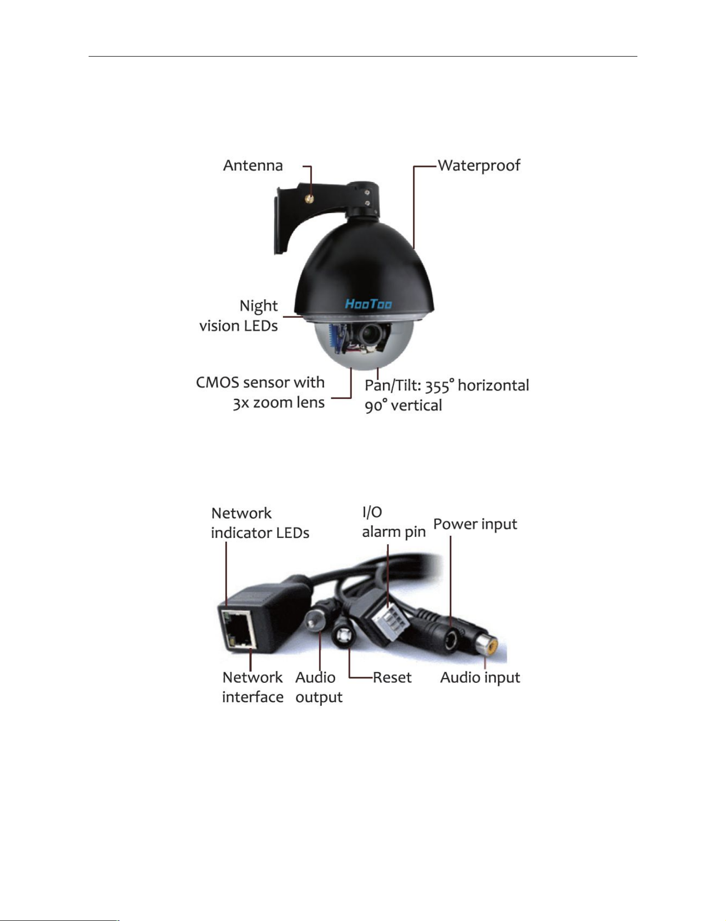
1.3 Product Views
1.3.1 Front View
Security Solutions Partner
1.3.2 Cable Interface
Figure 1.1
Figure 1.2
Audio Output: The jack is used to plug external speakers or audio output devices.
Audio Input: The jack is used to plug external microphones or audio input devices.
I/O Alarm Pin: 1 Alarm input (GND), 2 Input, 3 Output A, 4 Output B
Network Interface: RJ-45/10-100 base T
Network indicator: The green LED will be on when the network is connected. The yellow LED will blink
when data is transferred.
Reset: Press and hold the RESET button for about 15 seconds, all the parameters will be back to the factory
Page 5
Security Solutions Partner
5
default settings. (Please keep the power on when using RESET)
Power: DC 12V/2A power supply
1.4 PC System Requirements
System configuration requirements: (Example for viewing four IPCAM)
CPU: 2.06GHZ or above
Memory: 256M or above
Network Card: 10M or above
Display Card: 64M or above memory
Recommendable Operating System: Windows 2000/ XP/ Vista/ 7
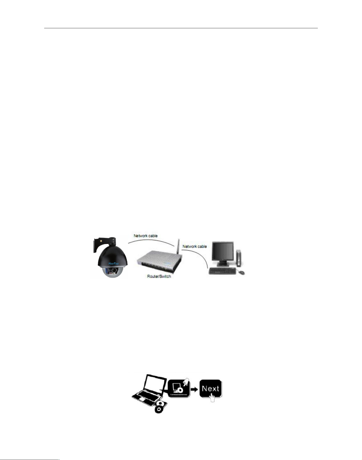
1.5 Hardware Instruction
Follow the steps below to set up your camera hardware. Make sure to follow each step carefully to ensure that
the camera operates properly.
1. Install the Wi-Fi antenna
2. Plug the power adaptor into the camera
3. Plug the network cable into the camera and router/switch
4. It takes approx. 30 seconds to boot up the camera, then you will find the IP address from
“IP Camera Tool” (Figure: 1.8)
5. When the power is on and network cable connected, the green LED of the panel will stay on,
The yellow LED will keep flashing.
Figure1.3
1.6 Software Installation
Attention: For a smoother installation process, we suggest that turn OFF your Firewall and Antivirus before
install the ActiveX, Don’t worry, it is safe.
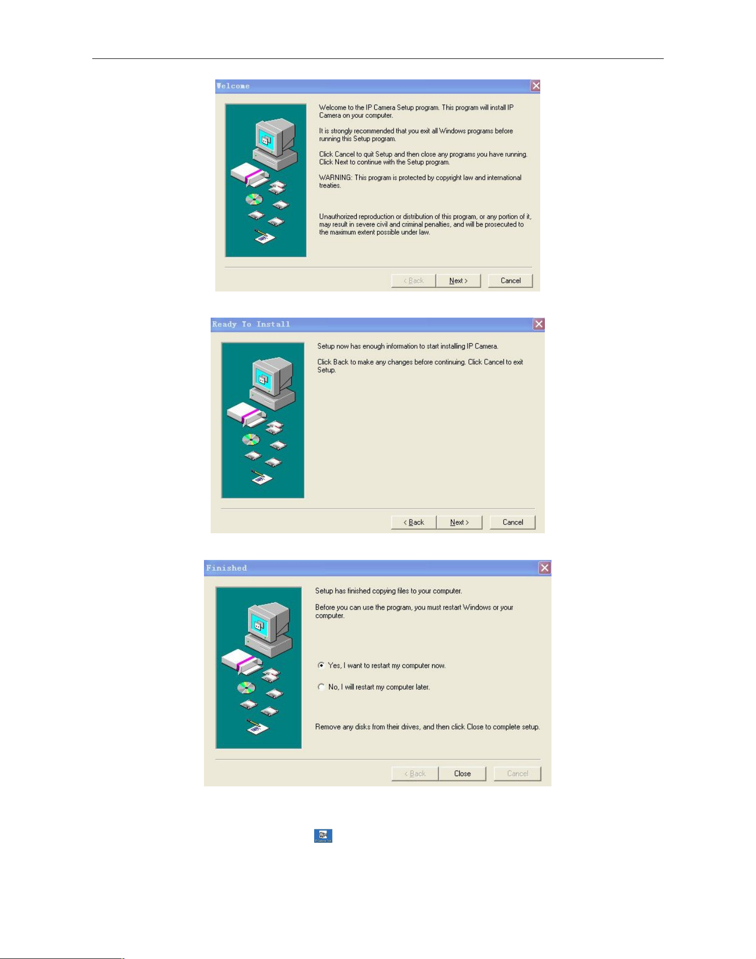
Install the following software:
1. IP Camera Tool: Open the CD, double click “IPCamSetup.exe”, click next, you will complete the software
installation.(figure1.5/ 1.6/ 1.7)
2. ActiveX: Double click “Appinstall.exe”—“Next”—“Install”—“Finish”.
Figure1.4
Page 6
Security Solutions Partner
6
will be displayed on your desktop automatically.
Figure1.5
Figure1.6
Figure1.7
After this done, the icon “IP Camera Tool”
Page 7

Security Solutions Partner
7
Figure1.8
Note: The software searches IP Servers automatically over LAN.
There are 3 cases:
1. No IP Cameras found within LAN. After searching for 1 minute, the Result Field will show “not found IP
Server” and the program will shut down automatically.
2. IP Cameras have been installed within your LAN. All the IP Cameras will be listed and the total number is
displayed in the result field as shown in Figure 1.8
3. The IP Cameras installed within LAN do not share the same subnet with the monitoring PC. A prompt as
shown in result field (prompt: Subnet doesn’t match, double click to change!). Click the left mouse button to
CAUTION: Before installing and using the product, please read the following precautions carefully and make
sure they are fully understood.
Use only the power adaptor included with the product. Using unauthorized power adapters may cause
damage to your IP Camera.
IP Camera terminal shall be installed in an indoor environment where there is no rain or snow.
Do not touch the lens of the IP Camera. The optimum focus range has been set before it is delivered out of the
factory. If you turn the lens, it may cause incorrect focus and vague images.
Do not turn the Pan/Tilt by force, it may cause damage to internal components of the Pan/Tilt.
For firmware upgrading, please always contact us first via support@hootoo.com.
2. SOFTWARE OPERATION
2.1 IP Camera Tool
When the Device has been mounted properly, you can double click the Icon “IP Camera Tool” and a dialog box
as Figure 1.8 will pop up.
Page 8
Security Solutions Partner
8
choose the prompt and click the right mouse, choose Network Configuration to set the static IP address of
the Camera to the same subnet as LAN. (Figure 2.2)
NOTE: If it shows” Subnet doesn’t match, double click to change!”, you can also choose ”Obtain IP from
DHCP Server” to get a dynamic IP. (Figure 2.1)
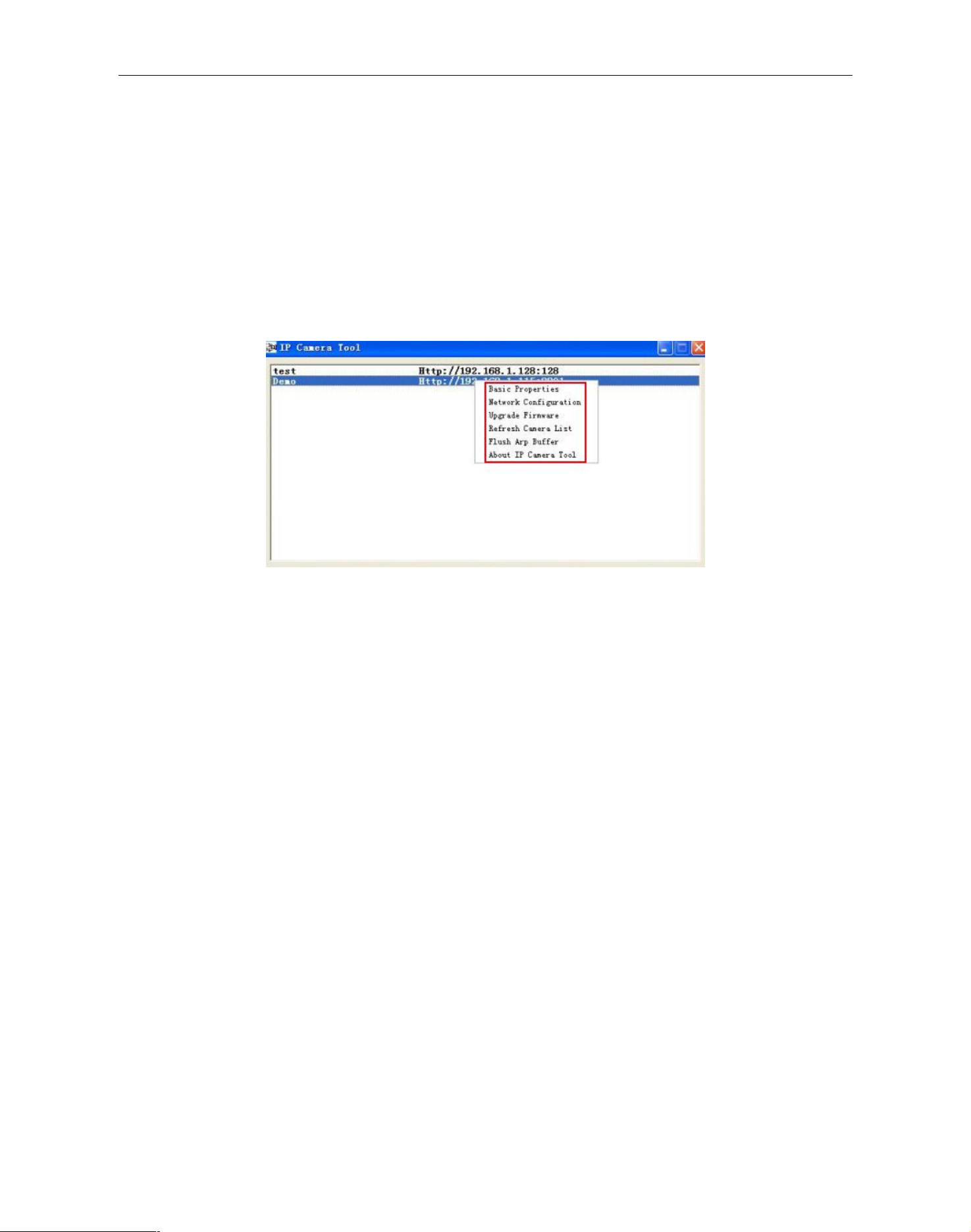
2.1.1 Six Options
Choose the IP Camera list and Click right mouse, there are six options: (Figure 1.9)
Basic Properties, Network Configuration, Upgrade Firmware,
Refresh Camera List, Flush Arp Buffer, About IP Camera Tool.
Figure1.9
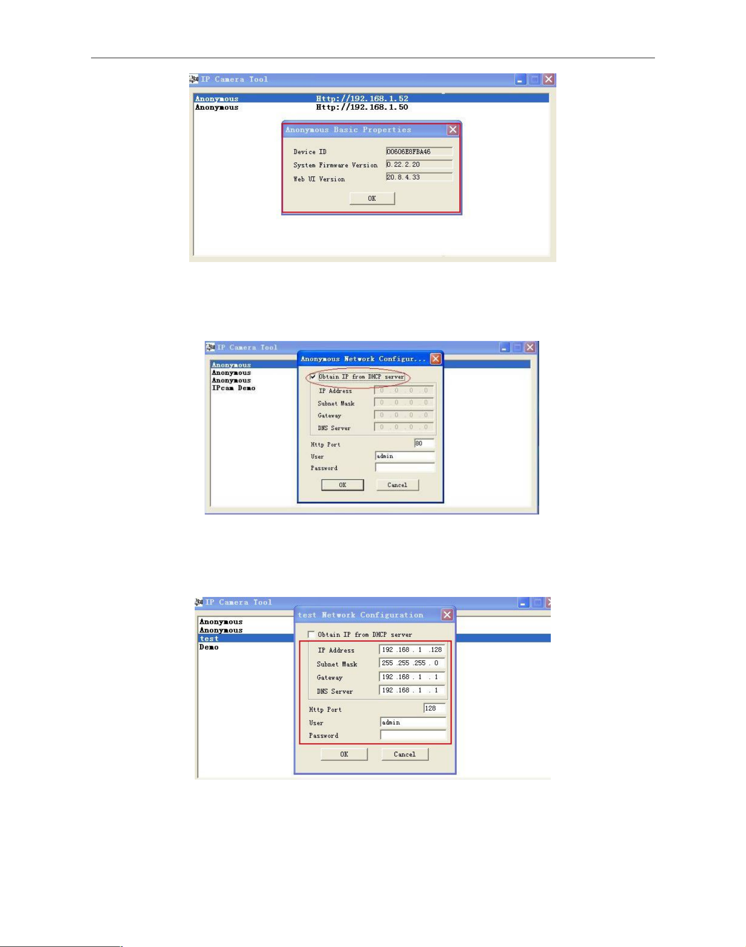
2.1.1 .1 Basic Properties
There is some device information in the Basic Properties, such as Device ID, System Firmware Version,
Web UI Version.(Figure 2.0)
The Device ID is the camera’s MAC ID (or Mac Address), which should be the same as showed on the
sticker at the bottom of camera. Every camera has its unique MAC ID.
Sometimes, if there is no IP address shown on the IP Camera tool, it might be blocked by a firewall. Add the
MAC ID to the router, and give it a fixed IP or add the MAC ID as a trusted site. There are two MAC Addresses,
one is Device MAC ID, the other is WIFI MAC ID.
WIFI MAC ID, you can find it from the sticker at the bottom of the camera, if this is sticker lost, you can login
your WIFI router, check the host status, which will show all the WIFI devices connected to this router, you can
also find the IPCAM’s WIFI MAC ID there.
Page 9
Security Solutions Partner
9
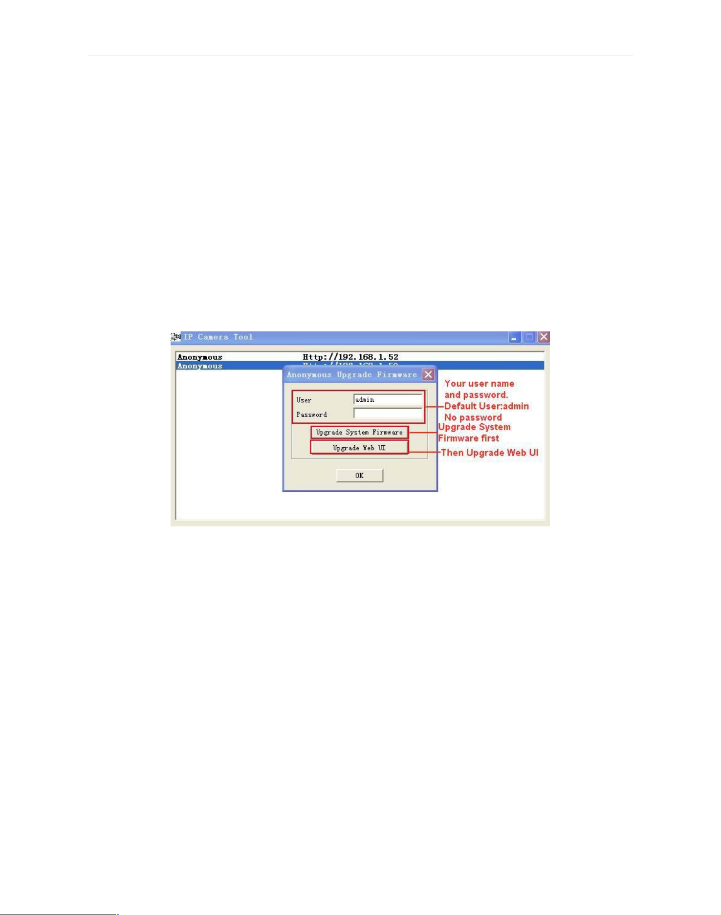
Figure2.1
Obtain IP from DHCP server: If clicked, the device will obtain IP from DHCP server. In other words, the
camera will have a dynamic IP. (Make sure the Router which the camera is connected to has DHCP function
and DHCP is enabled). (Figure 2.1)
Figure 2.2
IP address: Fill in the IP address assigned and make sure it is in the same subnet as the Gateway, and the
subnet should be the same as your computer or router. (I.e. the first three sections are the same)
Subnet Mask: The default subnet mask of the equipment is: 255.255.255.0. You can find the subnet mask
from your PC or router.
Figure2.0
2.1.1.2 Network Configuration
In this page, you can configure the Network parameter.
Page 10
Security Solutions Partner
10
Gateway: Make sure it is in the same subnet with your PC’s IP address. Gateway is the LAN IP of your router.
DNS Server: IP address of IPS network provider. You can also set it’s the same as the Gateway.
NOTE: You can find the Subnet Mask, Gateway, DNS Server from your router, or check the local connection
status of your computer to get all the parameters. Normally two DNS servers are optional.
Http Port: LAN port assigned for the equipment, default is 80. You could set another port number like 81, 801,
8001 etc.
User: Default administrator username is: admin (all lower-case)
Password: Default password is blank, no password.
NOTE: If the prompt “subnet doesn’t match, double chick to change!” appears, please set the IP Address,
Subnet Mask, Gateway, DNS Server once again, or enable Obtain IP from DHCP server.
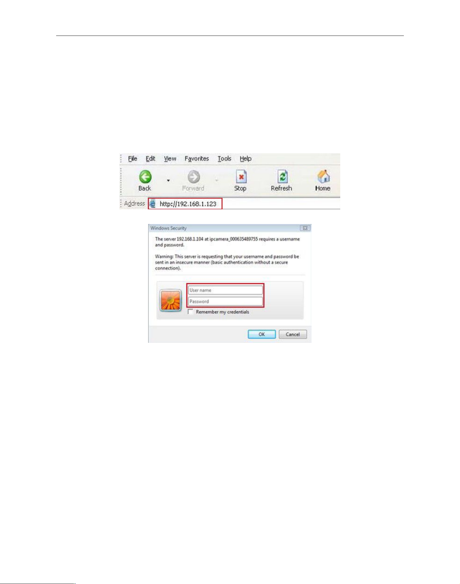
2.1.1.3 Upgrade Firmware
Enter the correct Username and Password to upgrade system Firmware and Web UI. If you upgrade the
camera, Please upgrade system firmware first and then upgrade Web UI.(Figure 2.3)
Figure 2.3
Please download the firmware package before upgrade.
Follow the upgrade document in the package carefully to upgrade. Please read over the readme.txt file before
you do upgrade.
CAUTION: Sometimes, your camera may be damaged if not upgrading properly.
If your camera works well with the current firmware, we recommend that you don’t update it.
NOTE: When upgrading, please keep the power on, and use a direct connection with your network cable.
2.1.1.4 Refresh Camera List
Refresh camera list manually.
2.1.1.5 Flush Arp Buffer
When your cable network and wireless network of the device are fixed IP addresses. There is a problem you
may encounter when searching for the camera IP but can’t open the camera web page. You may try to use
Flush Arp Buffer.
2.1.1.6 About IP Camera Tool
Page 11
Security Solutions Partner
11
Check the IP Camera Tool Version and IP Camera ActiveX Control Version here.
2.2 Camera Login
You can access the camera through IP Camera Tool or IE, Firefox, Safari, Google Chrome or other
browsers.
1. Double click the IP address of the IP Camera listed (Figure 1.8). The default browser you use will run
automatically and open the camera login interface. (Figure 2.6)
2. To access the camera by IE Browser directly, just type the camera’s IP address, for example, if the camera’s
IP address is 192.168.1.123:
Figure 2.4
Figure 2.5
The default user name is admin, no password
Input the correct user name and password, the Sign In interface will pop-up.
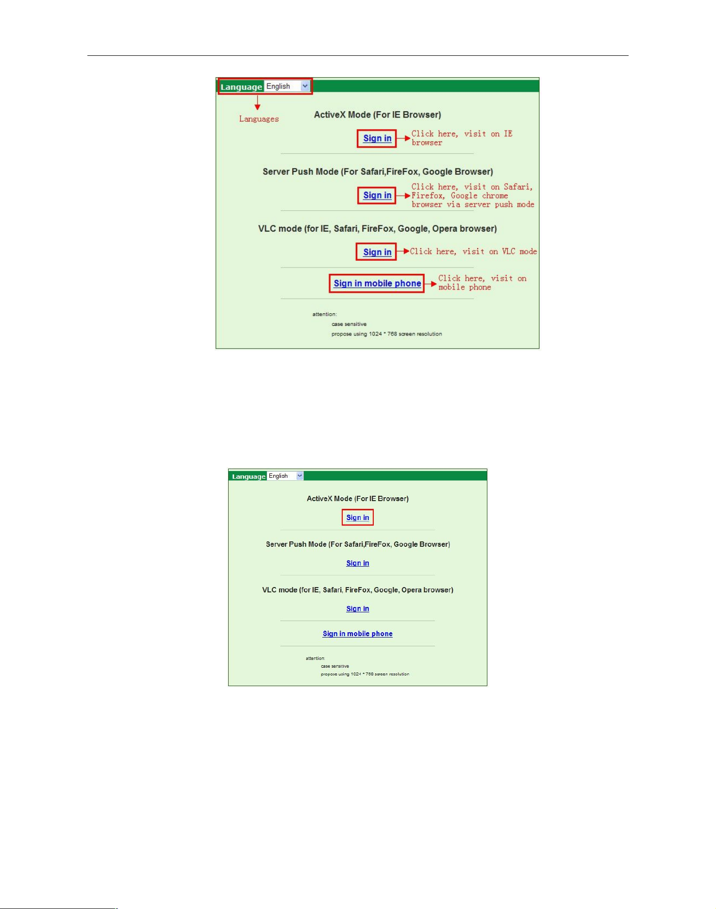
There are three modes to login (figure 2.6).
Page 12
Security Solutions Partner
12
Figure 2.6
(1) Active Mode (For IE Browser): available in IE6.0 or above
(2) “Server Push Mode”: available in Firefox, Safari, and Google Chrome browser.
(3) “Sign in mobile phone”: available for Mobile phones
2.3 For IE Browser
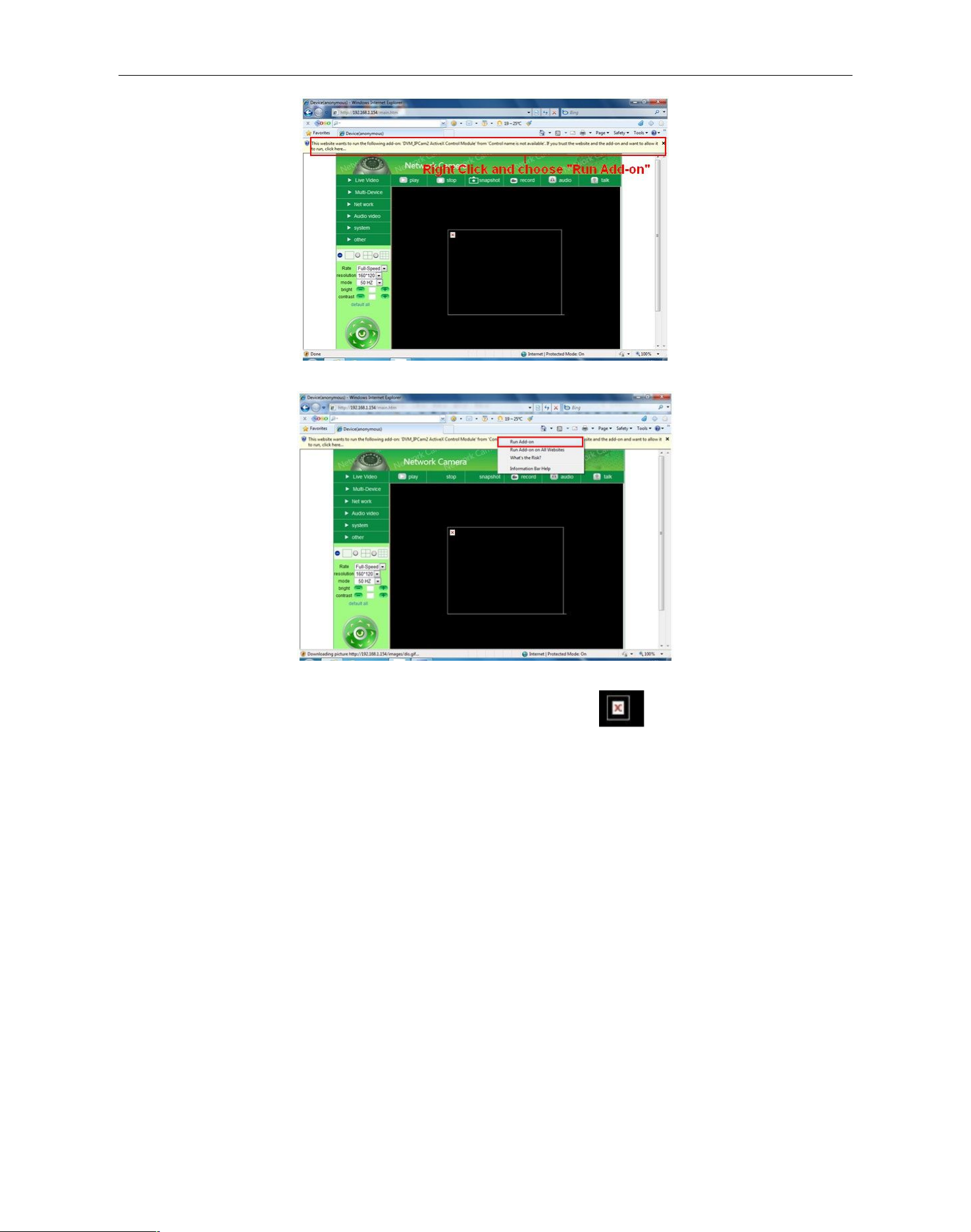
Choose Active Mode (For IE Browser), and sign in.
Figure 2.7
The first time you login to the camera, you might get the ActiveX prompt as the picture above, please click the
prompt and choose Run Add-on, refresh and login the camera again, then you will see live video, shown as
below:
Page 13
Security Solutions Partner
13
Figure2.8
Figure 2.9
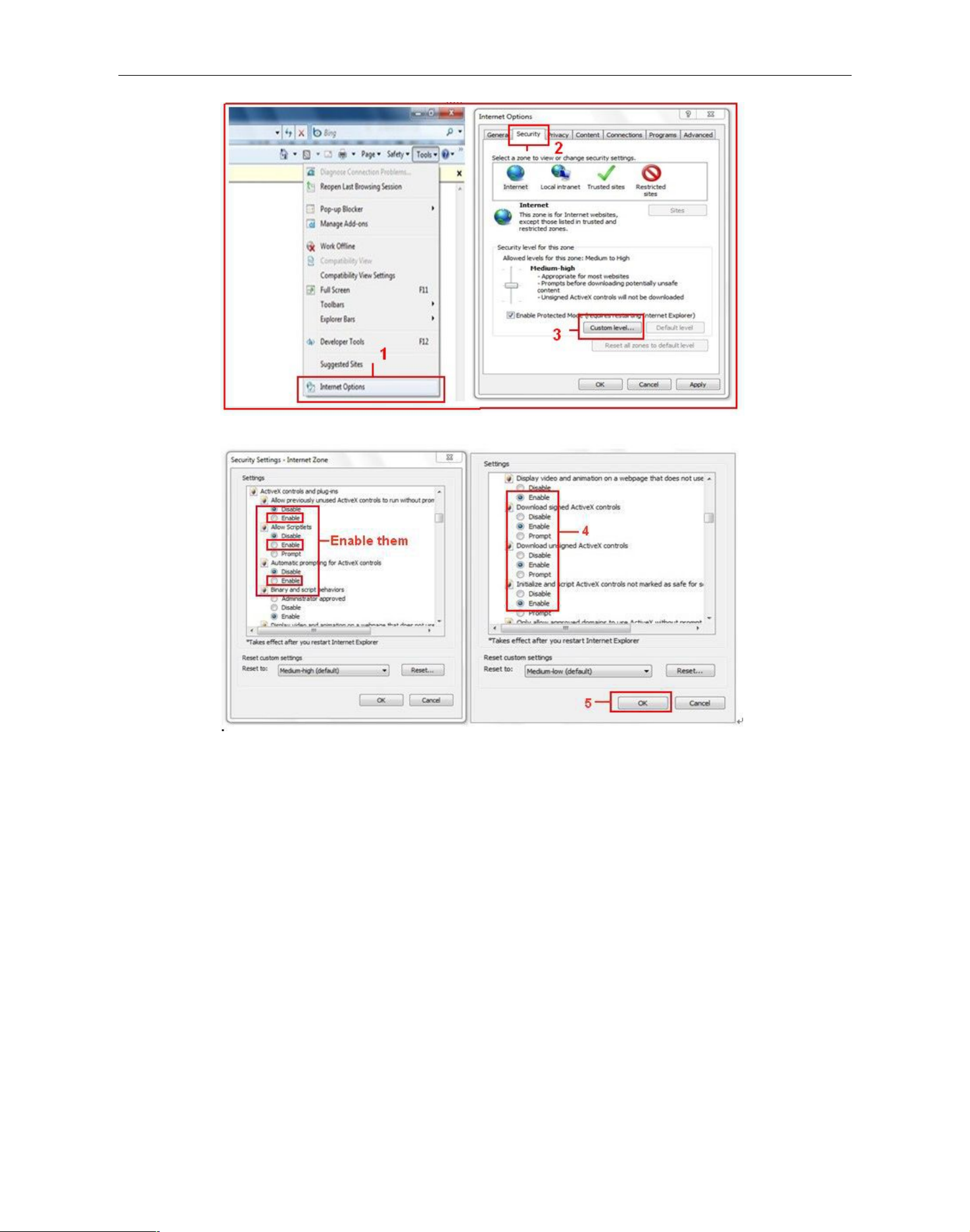
Note: If there is still no live video after running ActiveX, and a red cross shows in the center of the
screen, or even just a black screen, please try to enable the ActiveX options in IE security settings.
Please do the follow steps:
1. Close the firewall on your computer.
2. Change the ActiveX settings, “IE” browser > “Tool” > “Internet Options” > “Security”> “Custom Level” >
“ActiveX control and Plug-ins”, all the ActiveX options set to be “Enable”:
Also:
Enable: Download unsigned ActiveX controls
Enable: Initialize and script ActiveX controls not marked as safe
Enable: Run ActiveX controls and plug-ins
Page 14
Security Solutions Partner
14
Figure3.0
Figure 3.1
In addition: you can also click “Start” menu->“Internet Explorer”, choose “Internet attributes “ to enter, or via
“Control Panel” ->“Internet Explorer”, enter to Security setting.
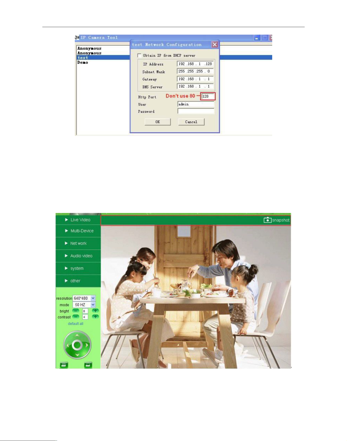
If ActiveX is running, but you still could not see live video, please try using another port number. Don’t use port
80, use other ports such as 128, 1008 etc.
Page 15
Security Solutions Partner
15
Figure 3.2
NOTE: Make sure that the firewall or anti-virus software doesn’t block the software or ActiveX. If you couldn’t
see live video, please close your firewall or anti-virus software, and try again.
2.4 For Safari, Firefox, Google Browser
Choose Server Push Mode (For Safari, Firefox, Google Browser), and sign in
Server Push Mode doesn’t support ActiveX, so some functions are not available, such as Play, Stop, Record,
Audio, Talk etc. if you want to use these functions, please use IE browser.
Figure 3.3
Page 16
Security Solutions Partner
16
2.5 For Mobile Phone
Choose Sign in mobile phone, and sign in.
Mobile phone doesn’t support ActiveX, only some basic functions can be available in this mode.
It supports most smartphones with a 3G/4G connection. Usually, if the mobile phone supports network video,
then it can work with our IP Camera.
Figure 3.4
2.6 ActiveX Mode (For IE Browser)
Login the camera in ActiveX mode, the main User Interface will be shown as below:
NOTE: There are 3 levels of users, Visitor, Operator, Administrator, if you login with different users, the
features/operations are different. (See 3.11 User Settings, Figure 8.5)
2.7 For Visitor
When logged in as Visitor, you can enter the IP Camera for visitor.
Visitor is the lowest level with only some operations available
Page 17

Security Solutions Partner
17
Figure 3.5
Channels:
Our IE software supports 9 channels total. Clicking can get different windows.
: Click this one, you can view the main channel of the camera.
: Click this one; you can view 4 Channels of cameras that are connected, from CH1 to CH4.
: Click this one; you can view 9 Channels of cameras that are connected, from CH1 to CH9.
NOTE: If you want to view 4/9 channels, you should set the Multi-Device first (See 3.1 Multi-Device
Settings)
Status of Channels:
There are 9 icons at the bottom of the UI which show the status of each channel of the camera.
: Grey color, means there is no device connected to the main device from this channel.
: Green color, means the device is connected from this channel, and it works well.
: Red color, means the device of this channel is recording.
: Yellow color, means set this channel in multi-device already, but it fails to connect to the main device.
Page 18

Security Solutions Partner
18
OSD Settings:
Figure 3.6
OSD: Means “On-Screen Display”, click “Audio video” > “OSD”, set display date and time on the video.
Disabled: Click this one, means clear the OSD.
Color: Can set the OSD text color as black, yellow, red, white, blue etc.
Add time stamp on record: Click this, there will be time OSD on record video files.
Figure 3.7
Page 19

Security Solutions Partner
19
Rate and Resolution:
Rate: Set video framerate here, from “full-speed to 1fp/5s”. (Figure 3.8)
Resolution: Set the resolution to be 160*120/ VGA(640*480)/ QVGA (320*240). (Figure 3.9)
NOTE: When doing recording, Rate and Resolution parameter settings is very helpful for getting small
sized recording files, the lower parameter to get the smaller file.
Figure 3.8 Figure 3.9
TOP Menu:
Figure 4.0
: Click it to get live video. When you want to go back to live video from other menus, just click it.
Only under live video, you can do the operations on the right side, such as play, stop, snapshot etc.
: Click it to get into play mode, when you click stop icon, the video will be stopped, then click
play icon, it will show the video again.
: Click it to stop the live video. You can click the play icon if you want to see live again.
: Click it to get snapshot. It will show the date and time of the snapshot you get, when you want
to save it, you will find the snapshot file named by “snapshot_MAC ID_date_time”.
: Click it to start recording manually, and the icon will change to red color , click it
again, it will stop recording. The record file will be saved to the folder you set. (Figure 10.8-Figure11.0)
: Click it to hear the sound around the camera, if you plug a earphone or a speaker in the
computer which you are using, you will hear the sound around the camera. This IP Camera has a built-in
microphone, when you click it to start work, the icon will change to red color , click it again, will stop
the audio function.
: Click it to start the talk function, first you have to plug a microphone in your computer. When
you are talking about something with the microphone from your computer, the sound will come out from the
built-in speaker of the camera, people beside the camera will hear the sound. If you are connected to an
external speaker from the audio output hole at the back of the camera (Figure 1.2), you will get better sound
effects. Click it once, the icon will change to red color , click it again, will stop talk function.
Page 20

Security Solutions Partner
20
NOTE: For visitor, if you click other menus which visitor don’t have the right to operate it, there will be a pop-up
of the login interface (Figure 2.6), please input the user name / password for at least 3 times to login again.
2.8 For Operator
When logged in as Operator, you can enter the IP Camera with Operator mode.
For operator, it not only supports all the functions which for Visitor, and also supports these functions as below:
Figure 4.1
Audio Video Settings
Figure 4.2
Audio buffer: Click this icon, it will show five numbers, which means 1/2/3/4/5 seconds’ buffer of audio.
Page 21

Security Solutions Partner
21
Reversal: Click this icon to see the reversal image. Click again, will be back to normal.
Mirror: Click this icon to see the mirror image. Click again, will back to normal.
NOTE: You can choose Reversal and Mirror function when you set up the camera in a special position.
Mode, Bright, Contrast Settings
Figure 4.3
Mode: This mode is optional, 50HZ/60HZ for the users who use 50HZ/60HZ frequency, outdoor for the users
who want to use this camera to monitor their outdoor environment
NOTE: This camera normally should be used in an indoor environment
Bright: Set the parameters to adjust the image quality of the video. Click to adjust the value
Contrast: Set the parameters to adjust the image quality of the video. Click to adjust the value
Default all: Click it to set all the parameters back to factory settings.
NOTE: If you log into the camera, there is no video displayed, and the parameter of bright/contrast is blank,
maybe you can try to click “default all” to set the parameters back to factory settings to get live video.
Pan/Tilt Control
Figure 4.4
: Click this icon, camera will move up, you can click one by one or hold it to control the movement
: Click this icon, camera will move down, you can click one by one or hold it to control the movement
NOTE: It is the same operation as left, right etc.
: Click this icon, the lens will zoom in, and the previous image will become larger, it supports 3Xzoom.
: Click this icon, the lens will zoom out, and the previous image will become smaller
: Click this icon, camera will rotate left and right, means horizontal patrol, click to stop it.
: Click this icon, IO output Switch ON. Click to set it OFF.
Page 22

Security Solutions Partner
22
on the live video, left click to control direction, eight directions are available. This is
very convenient for Pan/Tilt operation.
Double click right mouse again to exit.
Preset Settings
Figure 4.5
: Set Preset Position. It supports 8 preset positions. First, control the camera rotate to the desired position
you need to set, click the Set Preset Position button , it will pop-up a dialog frame(Figure 4.5), choose
any number (1-8) you want to set it to.
NOTE: Set different positions with the same number, camera will record the last position setting only.
: Call Preset Position. It supports 8 preset positions. If operator wants to monitor an important area quickly
and precisely, just click Call Preset Position button , it will pop-up a dialog frame(Figure 4.5), choose the
number, then camera will rotate to the preset area automatically.
If you want to use Call Preset Position, you have to Set Preset Position first.
NOTE: For Operator, if you click other menus which operator don’t have the right to operate it, there will be a
pop-up of login interface (Figure 2.6), please input the user name / password for at least 3 times to login again.
2.9 For Administrator
Details see Settings as Administrator (details3.1-3.22).
.
3 Settings as Administrator
When logged in as Administrator, you can enter the IP Camera for Administrator.
Administrator supports all the settings and operations of the camera; you can set and control it freely
There are some special functions only for administrator, as shown below:
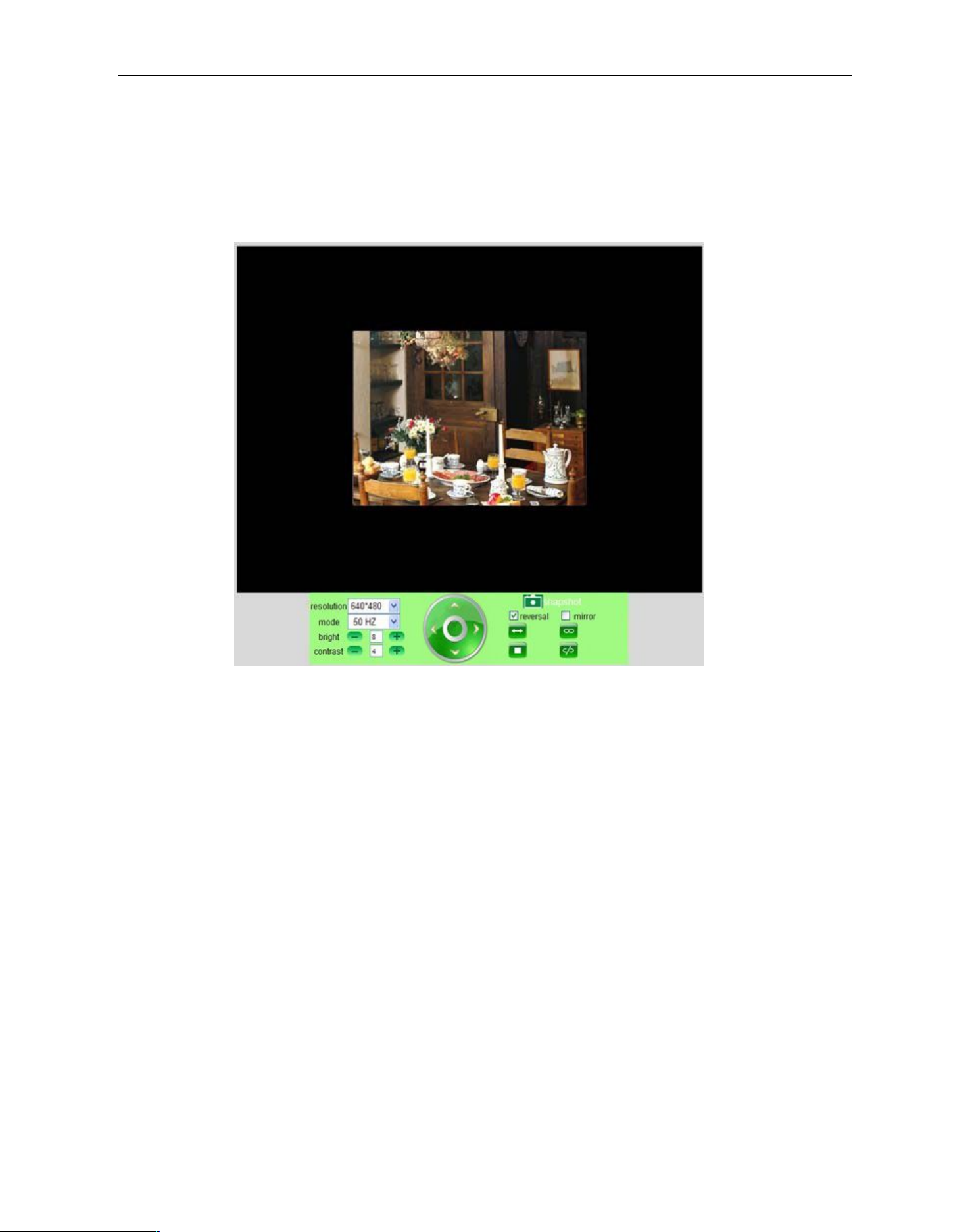
RECOMMENDATION:
Image PT function: Image PT function is recommended, you can control the camera direction on the live
video. Double click the right mouse on the live video to enable this function, and you will see a white &
transparent arrow
Page 23

Security Solutions Partner
23
Figure 4.6
3.1 Multi-Device Settings
Multi-Device Settings
This camera can support max. 9 channels device at the same time.
3.1.1 Set Multi-Device in LAN
In the Multi-Device Settings page, you can see all devices searched in LAN. The 1st device is the default one.
You can add more cameras listed in LAN for monitoring. This web software supports up to 9 IP Cameras
online simultaneously.
Click The 2nd Device and click the item in the Device List in LAN, it will fill the Alias, Host, Http Port
automatically, then input the correct user name and password, and click Add. Once finished setting up your
device(s), please click Submit.
Page 24

Security Solutions Partner
24
Figure 4.7
Click Live Video and then select to see four channels, or click to see nine channels.
Figure 4.8
Page 25

Security Solutions Partner
25
Figure 4.9
3.1.2 Set Multi-Device for WAN
If you want to view your cameras from the internet, you have to add these devices by DDNS domain name.
Make sure all these cameras you want to add have been set to DDNS successfully. (View 3.7 DDNS Service
Settings)
Login the first camera by DDNS domain name and port, this camera will be set as the host camera.
Figure 5.0
Click Multi-Device, select Multi-Device Settings. Choose the 2nd Device; fill in the 2nd camera’s Alias, Host,
Http Port, User, Password by manual, click Add. Set more devices in the same way, after all done, please click
Page 26

Security Solutions Partner
26
Submit.
NOTE: The Alias is optional; you can set the alias as you desire. The Host must be the camera’s DDNS
domain name, and without “http://”, it’s not the LAN IP address.
If you have several cameras, you can use the same DDNS domain name, just set different port numbers for
each different camera.
Figure 5.1
Note: Add the other camera in the same way, Click submit to add all of them.
Page 27

Security Solutions Partner
27
Figure 5.2
Click Live Video and then select to see four channels, or to see nine channels.
In this case, you can see all the cameras from a remote position by internet, for example, if you are on the
business trip, you can use the first camera’s (Host camera) DDNS to view all the devices via internet
Figure 5.3
3.1.3 Upgrade Device Firmware
If you want to upgrade the camera, please upgrade Device Firmware first, then upgrade Web UI.
Click Browse and choose correct bin file, then click Submit to upgrade.
NOTE: Before doing upgrade via Browser, please make sure the IP Camera Tool of your computer could find
the camera’s IP.
Attention: Please keep the power on during upgrading, it is recommended to be directly connected with your
network cable.
Figure 5.4
Page 28

Security Solutions Partner
28
3.1.4 Restore Factory Settings
Click Restore Factory Settings, a pop-up will prompt, select OK, all the parameters will be returned to factory
settings, and the device will reboot.
Figure 5.5
3.1.5 Reboot Device
Click Reboot the device, a pop-up will prompt, select OK, then the device will reboot
Figure 5.6
3.2 Network Settings
Click Network, will pop-up the prompt as below:
3.3 Basic Network Settings
Here you can fix the camera’s IP address; set the static IP address of camera manually.
You can also do the same settings from IP Camera Tool. (Figure 2.3)
Page 29

Security Solutions Partner
29
Figure 5.7
If you don’t know Subnet Mask, Gateway, DNS Server, please check the Local Area Connection Status of your
computer; it contains all this information, steps as below:
1. Control PanelNetwork ConnectionsLocal Area Connections Support Details
2. Find the local connection icon from taskbar, left click , choose Support Details
Figure 5.8
Figure 5.9
Page 30

Security Solutions Partner
30
If you don’t know the DNS Server, you can set it the same as Gateway.
If the router supports DHCP function, you can choose “Obtain IP from DHCP Server” to get dynamic IP.
Figure 6.0
Http Port: In most cases, you can leave this value as default, if your Internet Service Provider blocks this port,
you may change it to another port number such as 85.
3.4 Wireless Lan Settings
Figure 6.1
1. Make sure the router is a wireless router.
2. Make sure the Wi-Fi antenna is installed.
3. Make sure whether there is encryption of the WLAN of router, if there is encryption, keep the key.
4. Login the camera, click “Network”>”Wireless Lan Settings”>”Scan”, please scan 2 times, then you will find
the WLAN from the list, choose the one you use. (Figure 6.2)
5. If there is no encryption, just click “Submit”. (Figure 6.4)
6. If there is encryption, please input the share key, then click “Submit”. (Figure 6.5)
7. Wait about 30 seconds, the camera will reboot, then unplug the network cable.
Figure 6.2
Page 31

Security Solutions Partner
31
Figure 6.3
Figure 6.4
Figure 6.5
Page 32

Security Solutions Partner
32
3.5 ADSL Settings
When connected to the Internet through ADSL directly, you can enter the ADSL username
And password obtained from ISP.
Figure 6.7
3.6 UPnP Settings
Click UPnP Settings to choose Using UPnP to Map Port:
Figure 6.8
Select it and click Submit, then the camera will support UPnP port forwarding automatically.
It’s helpful for using DDNS, if your router support UPnP, then you do not need do port forwarding in router.
Figure 6.9
NOTE: Here UPnP only for port forwarding now. It has much relation with security settings of your router, make
sure the UPnP function of router is ON.
Attention: If your router doesn’t support UPnP function, it may show errors. We recommend you do port
forwarding manually in your router. (Details see Figure 7.4-7.9)
3.7 DDNS Service Settings
Page 33

Security Solutions Partner
33
Figure 7.0
There are 2 options:
Manufacturer’s DDNS: This domain is provided by manufacturer.
Third Party DDNS: This domain is provided by the 3rdparty, such as Dyndns, Oray, 3322 etc.
Figure 7.1
Third Party DDNS
If you use a third party DDNS, please choose the server you use, such as “3322.org” or “dyndns.org” as below:
Figure 7.2
Figure 7.3
You have to register an account first, keep the user, password, host, then input it.
NOTE: Only one DDNS can be chosen, for example, if you use manufacturer’s DDNS, the 3rdone won’t
work, if use the 3rdDDNS, the manufacturer’s one won’t work.
Page 34

Security Solutions Partner
34
Change the camera’s port.
The default port of the camera is “80”, please change “80” to any other one you like, such as “81”, “100”,
“8091” etc. Click “OK”, the camera will reboot, wait about 30 seconds.
Figure 7.4
Make sure the “Subnet Mask”, “Gateway”, “DNS Server” is the same as your router.
Set Port Forwarding in the router.
This is the most important step. Setting up your port forwarding in your router to the IP of your camera correctly,
then the DDNS will work. Because there are so many kinds of routers from all over the world, it’s difficult to
show universal steps, but here are some samples of different routers’ port forwarding settings as shown below,
just for reference:
TP-LINK:
1. Login the router.
2. Choose “Forwarding”, select “Virtual Servers”
3. Click the Add New button, pop-up below:
Figure 7.5
Fill the service port (except 80), IP address of the camera, then click Save
NOTE: The port and IP address should be the same as Camera.
Page 35

Security Solutions Partner
35
BELKIN:
1. Login the router.
2. Choose “Firewall”, select “Virtual Servers”
3. Input the port (except 80) and IP address, then click save.
NOTE: The port and IP address should be the same as Camera.
Figure 7.6
DLINK:
1. Login the router.
2. Choose “Advanced”, select “Virtual Servers”
3. Input the port, IP address, Protocol, then click save.
NOTE: The “public port” & “private port” should be the same as camera’s port, choose the protocol to be
“both”.
Figure 7.7
After all these 4 steps done, then you can use the DDNS freely, check the DDNS status from the camera as
below, and get the link of DDNS for internet view.
Page 36

36
Step: “Login”>”System”>”Device Info”:
Security Solutions Partner
Figure 7.8
3.8 System Settings
Figure 8.0
Figure 7.9
3.8.1 Device Info
You can find the information about Device ID, Firmware Version, Embedded Web UI Version, Alias, Alarm
Status, DDNS Status, UPnP Status and MSN status.
Page 37

37
3.9 Alias Settings
Security Solutions Partner
Figure 8.1
Default device name is anonymous. You set any new name for your camera here, then click Submit.
Figure 8.2
3.10 Date &Time Settings
Set the date and time for your camera.
Choose the Clock Time zone of your country.
You can choose Sync with NTP Server (Figure 8.3) or Sync with PC Time (Figure 8.4).
Figure 8.3
Page 38

Security Solutions Partner
38
Visitor: In this mode, you can only view. (Details 2.7)
Operator: You can control the direction of IP Camera and set some parameters. (Details 2.8)
Administrator: You can setup the advanced configurations of the IP Camera. (Details3.1-3.22)
Figure 8.4
3.11 Users Settings
Eight accounts are acceptable for this system. Here you can set the user names and password as
Administrator, Operator or Visitor, the permission for them as below:
Figure 8.5
Page 39

Security Solutions Partner
39
3.12 PTZ Settings
Figure 8.6
1. Go center on boot: The camera will rotate to the center automatically when it starts
2. PT speed: Set Pan / Tilt speed
3. Upward patrol speed: Set the speed of cruising upward
4. Downward patrol speed: Set the speed of cruising downward
5. Leftward patrol speed: Set the speed of cruising leftward
6. Rightward patrol speed: Set the speed of cruising rightward
NOTE: Value 0 means the fastest, value 10 means the slowest. In order to protect the camera’s motor, we
recommend that setting the speed to value 5.
3.13 Indicator Settings
Figure 8.7
Set the pilot lamp mode, the following three options:
(1) Non-connected network out: Twinkle while connected to the internet and turn off when departed
(2) Non-connected network with more slow-frequency flicker: Twinkle while connected to the internet and
move slower when departed
(3) Been extinguished: Keep OFF
3.14 Backup & Restore
Figure 8.8
Page 40

Security Solutions Partner
40
(1)Backup: Backup IP Camera settings, if you want to save all the current settings that you have set already,
you can click Submit, then all the parameters you set will store as a parameters bin file.
(2)Restore: Restore IP Camera settings, if you want to change the camera’s settings to a certain status
which has a backup, click Browse to load the bin file, then Submit it.
Log
Figure 8.9
Record User information, including weekday, date, time, user name, visitor IP address etc.
MSN Settings
NOTE: Set the port forwarding successfully before setting MSN (Refer to port forwarding in DDNS settings).
Then go to the MSN settings page, fill in the correct user name and password, add the MSN buddy, max. upto
10 friends, after submit, the user will be shown in your MSN friend list.
Click System—Device Info to check the MSN status.
Page 41

Security Solutions Partner
41
Run your MSN, open the chat dialog, type in the word “url?”, after a few seconds, you will get a reply for the
remote access ip address for this ip camera.
3.15 Other Settings
Figure 9.0
Here you can configure some additional functions such as Motion Detection, Alarm, IO Linkage, Schedule,
FTP Upload, Alarm Mail Alert, Record Path etc.
3.16 Mail Service Settings
Set Mail Service Settings to enable the camera send email alert when motion detection triggered.
Page 42

Security Solutions Partner
42
Figure 9.2
If it prompts these following errors when you click Test. Please check whether the information you filled in are
correct. Make sure all of them are correct and try it again.
1) Can’t connect to the server
2) Network Error. Please try later
3) Server Error
4) Incorrect user or password
5) The sender is denied by the server. Maybe the server need to authenticate the user, please check it and try
Figure 9.1
Sender: Make sure the sender mailbox server provider support SMTP, and the mailbox should not enable SSL
or TSL encryption too.
Receiver: Here you can set four receivers. For receiver, there is no SMTP limitation.
SMTP Server: The sender’s SMTP Server.
SMTP Port: The sender’s SMTP Port, usually is 25, some SMTP server have its own port such as 587.
Need Authentication: If there is SMTP user & password, please select authentication.
SMTP User: Input correct SMTP User here. Some SMTP User is the sender’s full email address, such as
test@qq.com, some are without suffix, only the username, such as test.
SMTP Password: Input correct SMTP password here.
NOTE: Please click Submit firstly before choosing Test.
You will see the test result after click Test.
Page 43

Security Solutions Partner
43
again
6) The receiver is denied by the server. Maybe because of the anti-spam privacy of the server
7) The message is denied by the server. Maybe because of the anti-spam privacy of the server
8) The server does not support the authentication mode used by the device
Report Internet IP by Mail: If selected, you will receive emails which contain the camera’s internet IP. When
camera power on or Internet IP changed, it will send the internet IP by mail. (For example: IPCAM's URL is
http://121.213.109.69:1008).
3.17 FTP Service Settings
Set the FTP Service, you can upload images to your FTP server when motion detection triggered.
Figure 9.3
Figure 9.4
FTP Server: If your FTP server is set up in LAN. You can set as Figure 9.3
If you have a FTP server that can be accessed from internet, you can set as Figure 9.4
FTP Port: Usually the port is 21
FTP Upload Folder: Make sure that the folder you plan to store images exists. The camera will not create the
folder itself. Also, the folder must be erasable.
FTP Mode: It supports standard (POST) mode and passive (PASV) mode
Upload Image Now: It will upload images when you select it. Here Upload Interval refers to the time between
the current image and the next image.
NOTE: Here upload image now means it can upload images freely, no alarm trigger is needed.
Page 44

Security Solutions Partner
44
Click Submit after these settings. Then click Test. You will see the following picture.
Figure 9.5
If it prompts error information as follows.
1) Cannot connect to the server. Please check FTP Server is correct or not.
2) Network Error. Please try later.
3) Server Error.
4) Incorrect user or password. Please check the username and password is correct or not.
5) Cannot access the folder. Please be sure the folder exists and your account is authorized
6) Error in PASV mode. Please be sure the server support PASV mode
7) Error in PORT mode. PASV mode should be selected if the device is behind a NAT
8) Cannot upload file. Please be sure your account is authorized
Please check if parameters you filled in are correct or not. The format of image is like 000DC5D008FA (IPCAM)
_0_20101115152525_25.jpg
Please check if your FTP server supports this format of file name
3.18 Alarm Service Settings
Figure 9.6
Enter Alarm Service Settings page to configure Motion Detection function.
3.18.1 Motion Detect Armed
If Motion Detect Armed is enabled, it will record and make a sound of alarm when there is motion detection
Page 45

45
triggered.
Security Solutions Partner
Figure 9.7
After enable motion detect armed, if there is motion triggered, the Alarm Status will turn to Motion Detect
Alarm. (Figure 9.8)
Figure 9.8
3.18.2 Motion Detect Sensibility
You can choose level 1-10; level 10 means the most sensitive, 1 means the least of all.
Page 46

Security Solutions Partner
46
Figure 9.9
3.18.3 Alarm Input Armed / IO Linkage on Alarm
If you want to connect external alarm devices, when it’s an alarm input device, choose Alarm Input Armed to
enable it, when it’s an output device, choose IO Linkage on Alarm to enable it.
Figure 10.0
There are two options for Trigger Level. (Figure 10.1)
High: When the external alarm device is closed, then the alarm triggered.
Low: When the external alarm device is switching off, then the alarm triggered.
Figure 10.1
There are two options for Output Level. (Figure 10.2)
High: Choose it, the IO Pins work as a switch which is closed.
Low: Choose it, the IO Pins work as a switch which is switching off.
Page 47

Security Solutions Partner
47
3.18.4 IO Pins for IO Alarm Linkage
Figure 10.2
Figure 10.3
I/O PINS: 1 .Alarm input 2 Alarm input 3 Alarm output 4 Alarm output
Input pins: The input pins can be used for 1-way external sensor input. For example, you may connect a
Person Infrared Sensor (PIP) to it for motion detection. When external sensor triggered, IP CAMERA can be
programmed to send an email with picture or control the internal relay output.
If you link an external alarm device with Pin3 and Pin4, when select Alarm Input Armed (Figure 10.0),
external alarm is enabled.
Output pins: The output pins can be enable IO linkage on alarm.
You can also use & to control IO output Switch ON/OFF (See Figure 4.4).
NOTE: All the pins work as switch only.
3.19 Send Mail on Alarm
If chosen, it will send a picture to the customer’s e-mail once alarmed. (First you should finish the Mail Service
Settings. Figure 9.1)
NOTE: It usually will send 6 snapshots by one email to your mailbox for each alarm triggered. Each alarm will
last for 60 seconds.
Upload Image on Alarm
Enable Upload Image on Alarm to set upload images to FTP once alarmed.
Upload Interval: Set the upload interval (Seconds).
NOTE: The total alarm time is 60 seconds.
Figure 10.4
Scheduler
Here you can set the camera alarm during the time you set. Choose Scheduler and set the date & time range.
(Figure 10.5) From Monday to Sunday, and every day divides into 24 hours, each hour divides into 4 quarters.
Page 48

Security Solutions Partner
48
Left click the frame of the time range, it will turn to blue color, which means the time you chose is alarmed.
Click it again, it will turn back to grey, means delete the scheduler.
NOTE: Make sure the date & time settings are correct first. (Figure 8.3)
ATTENTION: If you don’t choose Scheduler, the camera will alarm anytime when motion triggered.
Figure 10.5
Sound on Alarm
When motion detection triggered, there will be a beeping sound during the alarm, you can control this sound
here.
Enable it, there will be sound once alarmed.
Cancel it, there will be no sound once alarmed.
Record on Alarm
If you want the camera do recording for every alarm, choose Record on Alarm to enable it.
If you do not want the camera do recording once alarm triggered, cancel it here.
Figure 10.6
Once alarm is triggered, there will be some representation:
1. The corresponding status light turns Red and keeps blinking.
Figure 10.7
2. If you set Sound on Alarm, plug an earphone or a speaker to the computer you use, you can hear the
beeping sound when alarmed. (Figure10.6)
3. If you set Record on Alarm, the camera will record automatically for approx. one minute. You can find the
record file in the folder which you set. (Figure 10.9)
4. If you set Send Mail on Alarm, you will receive an email alarm alert once motion triggered. (Figure 10.0)
5. You can also set Scheduler to enable the camera to sends emails during a special time range you want.
(Figure 10.5)
6. If you set Upload Image on Alarm, it will upload images to the FTP Server you set already once alarmed.
(Figure 10.4)
NOTE: Each alarm only last for approx one minute, all these above functions for motion detection triggered
only.
REC Automatically and Save to PC
When you enable motion detect and open the camera monitoring page on the PC. If there is an alarm
triggered, REC will start automatically for several seconds and save to the PC.
New Feature: Start the motion detection compensation and Alarm notification by HTTP.
Page 49

Security Solutions Partner
49
3.20 Path Settings
Figure 10.8
Here you can set record path and alarm record path for the camera.
Figure 10.9
Record Path: Here you can set the manually record path. Click , then start manually recording, the
record file will be saved to the specified path here set.
Alarm Record Path: Here you can set the alarm record path. When the motion is triggered, and record is
enabled, it will start alarm record automatically, the record file will be saved to the specified path here set.
Figure 11.0
NOTE: If you couldn’t set the path here in Windows 7 or Vista, please do it as below:
Windows7 or Vista’s security level is higher than Windows XP/2000, for “Path Settings”
1. User could add the Device IP address to the IE’s ‘Trusted sites’ firstly. The step is:
“IE browser→Tool→Internet Proper→Security→Trusted sites→Sites→Add”.
2. You can also run the IE as administrator, input the IP address of the camera manually. (Figure 11.1)
Figure 11.1
Page 50

Security Solutions Partner
50
3.21 Server Push Mode (For Safari, FireFox, Google Browser)
Choose Server Push Mode, log in to the camera, you will see the main user interface as shown below:
Figure 11.2
NOTE: Server Push Mode does not support ActiveX.
Play, Stop, Record, Audio, Talk, Multi-device settings, Path settings functions are controlled by ActiveX,
so if you use Safari, Firefox, Google chrome browser, it is impossible to use these options.
The other functions are the same as ActiveX Mode (For IE Browser)
3.22 Sign in mobile phone
If you are using a mobile phone, choose Sign in mobile phone, log into the the camera, then you will see the
main user interface as shown below:
Page 51

Security Solutions Partner
51
Figure 11.3
NOTE: Mobile phone Mode doesn’t support ActiveX.
In mobile phone mode, it only supports some easy functions, such as Resolution, Mode, Bright, Contrast,
Pan/Tilt control, Snapshot, Reversal, Mirror, IO Linkage functions
4. APPENDIX
4.1 Frequently Asked Questions
Note: Any questions you have, please check Network connections first.
Check the working status revealed by the indicators on the network server, hub, exchange and network card. If
abnormal, check the network connections.
4.1.1 I have forgotten the administrator username and/or password.
To reset the administrator username and password, press and hold down the RESET BUTTON for 15 seconds.
Release the power button and the username and password will be reset back to the factory default
administrator username and password.
Default administrator username: admin
Default administrator password: No password (blank)
4.1.2 Subnet doesn’t match, dbclick to change
If IP Camera Tool shows error information “Subnet doesn’t match, dbclick to change!” Please choose Obtain
IP from DHCP server. (Figure 2.2)
If it still show this error after obtain IP from DHCP server. Please check local area connection of your computer,
change subnet, gateway of the camera. Keep them in the same subnet of your computer. (Figure 2.3)
Page 52

Security Solutions Partner
52
4.1.3 IP Address configuration
Check whether IP address of the IP camera server shares the same subnet as your work station: Click My
Computer >Control Panel> Network & Dial-up Connections > LAN > Attributes >Internet Protocols
(TCP/IP), and check IP Address and Subnet Mask. Make sure they are in the same subnet when configuring
Camera’s IP address manually.
4.1.4 Can’t access IP camera in internet
There are some reasons:
1 ActiveX controller is not installed correctly (see more details: Figure2.9~Figure3.1).
2 The port which camera is used is blocked by Firewall or Anti-virus software. Please change another port
number and try again. (Figure3.2)
3 Port forwarding is not successful (see more details: Figure7.4~Figure7.9)
Double check these settings and make sure they are correct.
4.1.5 IP Camera Tool could not find camera’s IP
Please check if the camera is properly connected. Check if network cable is loose or not.
Make sure DHCP is enabled in your router, don’t enable MAC address filter.
Make sure that firewall or anti-virus software does not block the camera. You can add the camera as a trusted
site in your firewall or anti-virus software.
4.1.6 UPnP always failed
UPnP only contains port forwarding in our recent software. Sometimes, it may be fail to do port forwarding
automatically because of firewall or anti-virus software. It also has much relation with router’s security settings.
So we recommend you do port forwarding manually. You can view your camera by the internet successfully
after you do port forwarding manually in your router.
4.1.7 Couldn’t find the shortcut on desktop after install IP camera tool
If you use Windows7 or Vista, You could not find the shortcut on desktop after install the IP camera tool,
please check if the path of the tool port to is correct or not.
For example, as it was pointing to C:\Windows\System32\IPCamera.exe.
Please fix this by pointing the shortcut to the correct path C:\Windows\SysWOW64\IPCamera.exe. After this
you could use the shortcut without any problems.
4.1.8 I can’t change the record path
When you use Windows7 or Vista, you may be not able to change the record path for the security settings of
computer.
1. Please add the camera as a trusted site to solve this issue.
The step is: “IE browser→Tool→Internet Proper→Security→Trusted sites→Sites→Add”.
2. You can also run the IE as administrator; input the IP address of the camera manually.
4.1.9 I can’t find multi-device settings and record icon
Record and multi-device function are controlled by activeX controller.
Page 53

Security Solutions Partner
53
So if you use Safari, Firefox, Google chrome, it is impossible to use these functions.
4.1.10 Camera cannot connect wireless
If your camera could not connect wireless after you set wireless settings and plug out the cable. Please check
whether your settings are correct or not. (Details: Wireless LAN settings)
Normally, camera can’t connect wireless mainly because of wrong settings.
Double check the SSID, Encryption share key, Channel, should be the same as your wireless router.
Share key should not contain special characters, only word and number will be better.
Don’t enable MAC address filter.
4.1.11 I can’t see other cameras which in multi-device when remote access
If you want to view all the cameras in WAN, make sure that each camera you add in multi-device settings can
be login using the DDNS name and port number. Use DDNS domain name to fill in the host checkbox, not
camera’s LAN IP. Double check your settings. (Details: Set Multi-Device for WAN)
4.1.12 Only see black screen or unreasonable code when remote login
If you could access the login page in remote place, it indicates that your DDNS settings are correct. You could
not see living video but only some undefined characters, it may be the internet speed problems, especially the
camera work on Wi-Fi.
4.1.13 No pictures Problems with ActiveX Controller
If using IE browser to connect the camera for the 1sttime, maybe there is no image displayed, and there will be
a clue to install the ActiveX. You can do some settings to enable the ActiveX. (Details: For IE Browser)
4.1.14 Problems with network bandwidth
The image frame rate is subjected to the following factors:
1. Network bandwidth
2. PC performance, network environment and display preference setting (brightness, theme, etc)
3. The number of visitors (Too many visitors will slow down the image frame rate)
4. Choice of switch or hub (Use a switch for multiple IP Camera Servers rather than a HUB)
4.1.15 How to register an account from DDNS web
You can enter http://www.dyndns.com/ and register an account, more details please check the Quick
Installation Guide
4.1.16 Why pop-up the prompt” Fail to connect to the device…”?
This prompt only appears in the case of using multiple cameras.
When you set multiple cameras, the device status light change to yellow , then please make sure the
camera connected and works correctly.
Page 54

Security Solutions Partner
54
4.2 Default Parameters
Default network Parameters
IP address: dynamic obtain
Subnet mask: dynamic obtain
Gateway: dynamic obtain
DHCP: Disabled
DDNS: factory DDNS and third party DDNS
Username and password
Default administrator username: admin
Default administrator password: No password
5. Specifications
Specification:
Image Sensor 1/4" Color CMOS Sensor
Display Resolution 640 x 480 Pixels(300k Pixels)
Image Sensor
Audio
Video
Lens 3x Optical Zoom
Mini. Illumination 0.5Lux, F2.0
Lens Type Glass Lens
Viewing Angle 30.7°~ 69°
Input 1 channel audio input
Output 1 channel audio output
Audio Compression ADPCM
Image Compression MJPEG
Image Frame Rate 15fps(VGA),30fps(QVGA)
Resolution 640 x 480(VGA), 320 x 240(QVGA)
Flip Mirror Images Vertical / Horizontal
Light Frequency 50Hz, 60Hz, Outdoor
Video Parameters Brightness, Contrast
Ethernet Interface 10Base-T/100Base-TX Ethernet Port
Communication
Physical
Supported Protocol TCP/IP, DHCP, SMTP, HTTP, DDNS, UPNP, PPPoE, FTP, DNS
Wireless Standard IEEE 802.11b/g
Data Rate 802.11b: 11Mbps (Max.), 802.11g: 54Mbps (Max.)
Wireless Security WEP & WPA WPA2 Encryption
Pan/Tilt Angle Horizontal:355° & Vertical: 90°
Alarm Input 1 Channel on/off Input
Page 55

55
Alarm Output 1 Channel relay Output
Infrarde light 66 IR LEDs, night visibility up to 15 meters
Dimension 165*195*130 mm
Power
Environment
PC System
Requirements
Certification CE, FCC, RoHS
Power Supply DC 12V/2.0A
Power Consumption 10 Watts (Max.)
Operate Temper. 0° ~ 55°C
Operating Humidity 20% ~ 85% non-condensing
Storage Temper. -25°C ~ 55°
Storage Humidity 0% ~ 90% non-condensing
CPU 2.0GHZ or above (suggested 3.0GHz)
Memory Size 256MB or above (suggested 1.0GHz)
Display Card 64M or above
Supported OS Microsoft Windows 2000/XP/Vista/7
Browser IE6.0/7.0/8.0/Firefox/Safari/Google chrome or other standard browsers
Security Solutions Partner
6. CONTACTING TECHNICAL SUPPORT
While we hope your experience with the IP CAMERA network camera is enjoyable and easy to use, you may
also experience some issues or have some questions that this User’s Guide has not answered. Please contact
your reseller and ask for assistance first, if they could not resolve your issue, please contact our company.
If your cameras do not support some special functions shown in this manual, please contact our technical
support team via support@hootoo.com to obtain the latest Firmware and WEB UI file to upgrade your camera.
If you would like us to assist you with the setup on the camera, you can call us at 408-215-9707. This is the
number that goes directly to tech support team, find a tech representative and he shall assist you with the
setup.
Monday-Friday
Morning: 10:00-11:30 PST
Afternoon: 13:00-18:00 PST
NOTE: Some older versions can’t be upgraded to the latest version, if this is the case, please contact our
technical support team directly for assistance.
 Loading...