

Hood Seafurl 705, Seafurl 705 LD, Seafurl 810 LD, Seafurl 915 LD, Seafurl 810 Installation Manual And Owner's Manual
...
THIS
UNIT
IS
COMPLETF
WICHT
INSTALLAT'ION
AND
OWNEFI'S
AUGUST 1987
MANUAL
MANUAL
ilLH":5XW
\rs
"s
^V
ry
V7'
8"
A
g
,(n-
rf*
s
\
'ab-
h
t"*
v
_.,*.*
c
I
\t
705/810t9L5
READTHISPAGE
To
trouble-free operation
follow
below.
\'
2. Watch
3.If
4.
insure
the
Rinse
1.
fresh
it
don't
,,'-,!tt.
reat tnls unlt
reat tnls unlt
I
I
equipment
the
water.
jams
force
continued
simple
bearings
for
halyard
find out
it!
-
inspect
satisfaction
is necess
it
guidelines
regularly
wrap.
why
like other
llKe any otner
regularly.
it
listed
Look up!
-
and
ary
with
to
v
If
5.
dealer.
any
problem
persists
,
1
call
your
ffire
ftT
Eh
\,
*"GWO
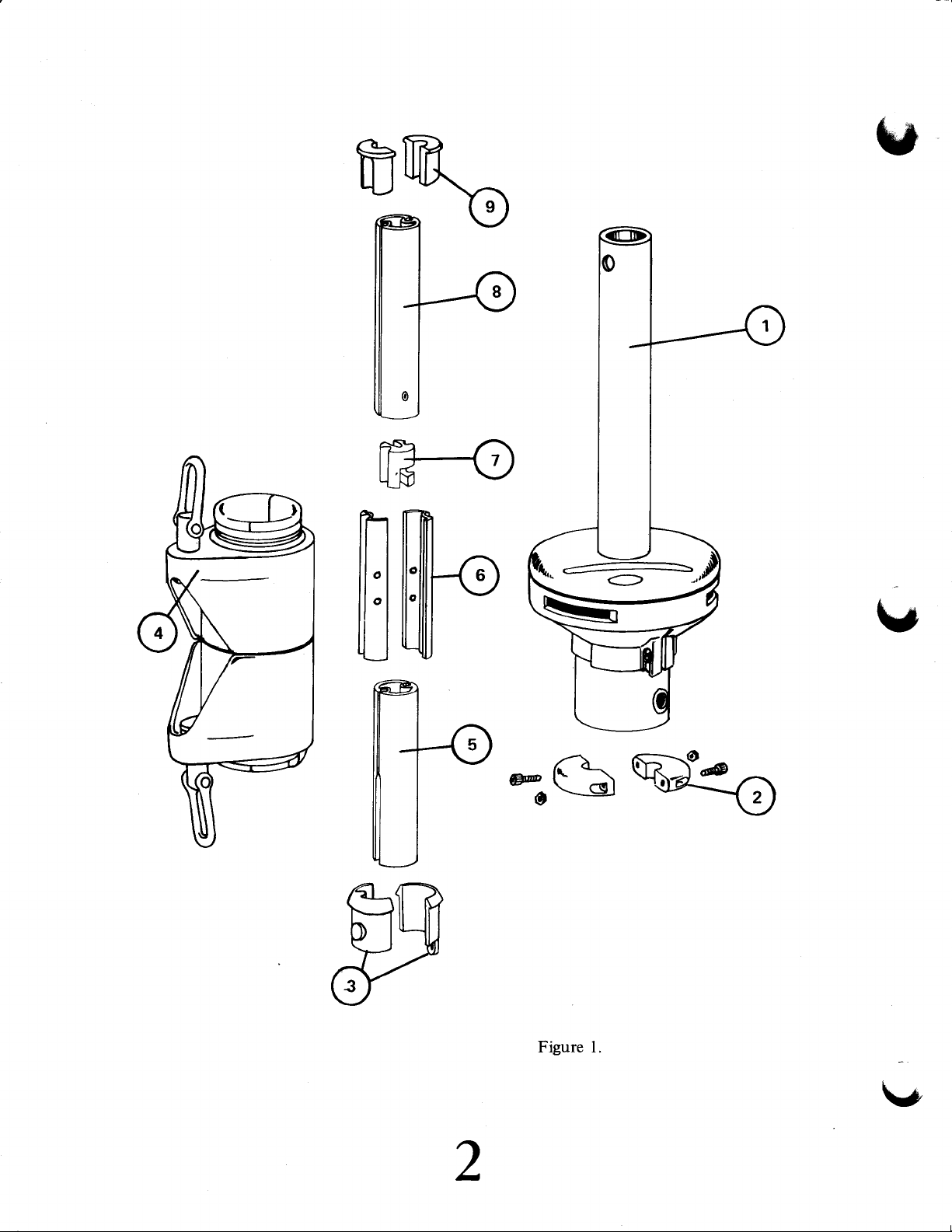
Figure l.
2
\/
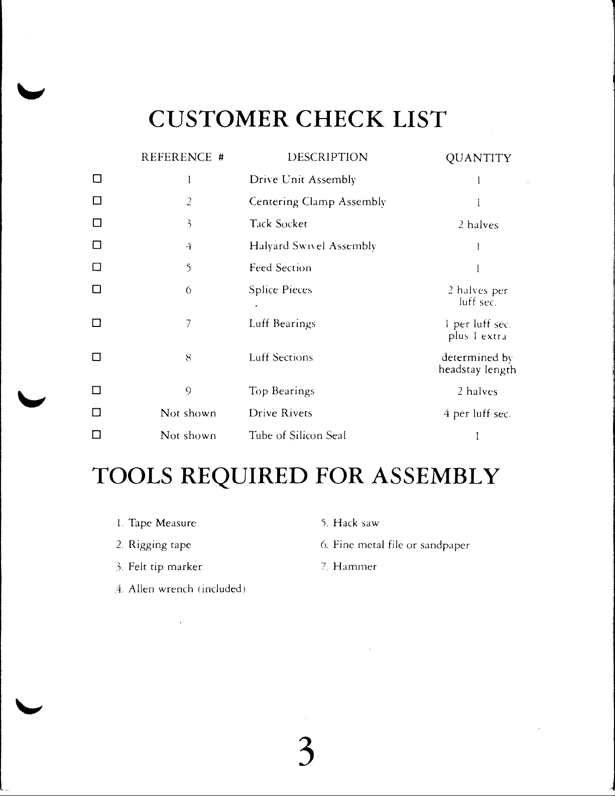
CTJSTOMER CHECK LIST
C
!
!
!
n
n
tr
!
n
!
n
REFERENCE
I Drive
2 Centering
I
1i
5
6
7
8
9
Not
shown
Not shown
# DESCRIPTION
Assembll'
Unit
Clamp
Trrck
Socket
Hali'ard Sg'rrei Assemblr'
Feed
Splice
Luff
Luf f
TopBearings
Drive Rivets
'Iube
ion
Sect
Pieces
Bearings
rns
Secri,
of Silicon Seal
Assemblr
QUANTITY
I
I
2 halves
I
I
h.rlvcs
2
luif
I pcr lufi
plus
determined
headstay
2 halves
1+
per luff
sec.
I
cxtr.i
lengrh
pe r
sec
br
sec.
TOOLS
i. Tape Measure
Rigging tape
2.
Felt tip marker
l.
Allen wrench rincluded
4.
REQUIRED
t
FOR ASSEMBLY
i. Hack
6. Fine metal
7.
saw
Hamrner
file
or sandpaper
-GD
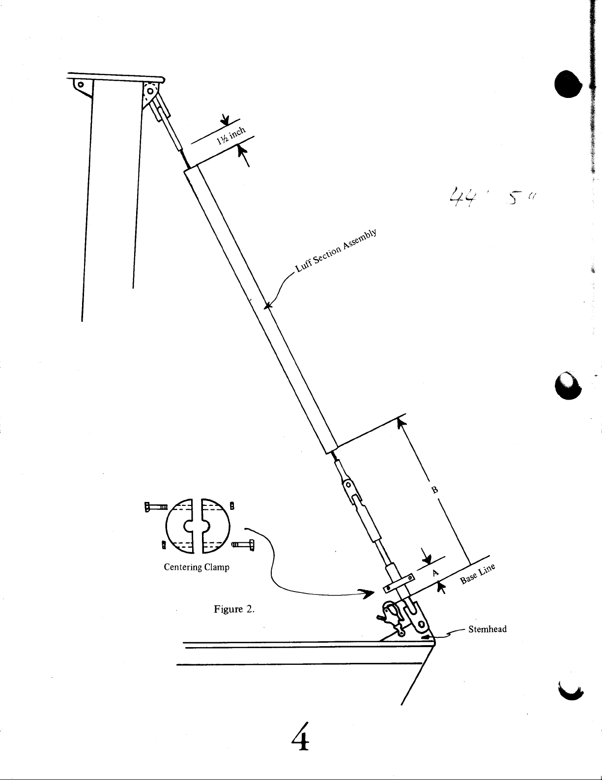
Figure
2,
INSTALLATION
MEASURING
l.
The Sea Furl
supplied). Choose
shackle) to
tack the genoa
fit through
Determine
by aligning the
shackle
tion with
the headstay is
mate
of where the Base
stemhead
adjustments
should be
The
t.
Centering
Drive
Unit on
halyard tension is
Determine
ing up from
Figure
on
Drive
Unit should be attached to the
an appropriate
use for this purpose.
to the
the
stainless
the
Base Line
stemhead fitting will
shackle
will
bear
on the grommet
a felt tip
marker on the headstay
on the ground rather than
configuration.
can be
made
made to determine this posirion to withint
Clamp
the
serves the
headstay. It also
released.
position
the
the Base
Line to
2) as follows:
grommer
steel
(from
parallel
position
Line
The
exact
after
the
of
Centering
the
THE HEADSTAY
deck
with
a
shackle
shackle
In most
which
with the headstay
after
position
the
unit is
purpose
serves
upper
(either
cases,
work. Make
on the bottom
a snap
the
shackle that
shackle
sure the
the
of
Drive
all other measurements
and noting
rhe
unir is installed.
(or
rurnbuckle,
the
on
will
be. basedon
of
boat,
the
installed.
Base
However,
Mark this
if
there
make your
the
shackle length
Line is
1".
of centering rhe lower
to hold the
Clamp
side of
the
the
on
clamp
furling
headstay
(measurement
or rwist
was
shackle
will
where
best
not
every
end of the
unit up when
by measur-
(not
used
to
will
Unit.
be taken)
the
posi-
is
one).
esti-
critical
effort
"A"
If
and
as
Mark
The
4.
contour
position
this
Centering
of
to the headstay
At this point,
5.
With the headstay
6.
to the location
Line
"B",
Figure
I'i+dei
i*ic,del
H.:,$s1
i'!a'i-il
r+iih
thi=
fsit
Clamp
the
headstay
(or
the
2) as
F-;=i
i3.p
Model #705-A:
Model
Model
on the headstay.
should be drilled
headstay
or
turnbuckle)
headstay
laid
should be
out straight
where the luff
follows:
S?rJ=
+*1t:i
#Fi=
i!.ni-:
nrark=i-,
- *
-
F
- E
c.1 th+
=L+
-
:3E
#810- A=lt/2"
#9It-A=2t/t"
out and filed if
turnbuckle.
proper
in its
removed
rhe ground,
on
section
1t/
i:r
q:J
tl-?.
h*e.rirt;1V
IYz"
Clamp the
location.
from
the
measure
assembly will
ara
necessary
Centering
boat.
up from the
(Dimension
start
to
fit the
Clamp
Base
-?
l v
-
[!
,,:
$-f-
r
.,
n
I
;,
.,
t,#
-.
;
-.)
Bearings
Top
T
I
Bearings
Luff
+
r
m[fi
[1[][]
-
.3
Splice
Pieces
.{-
An
G'I.
-
6
\}
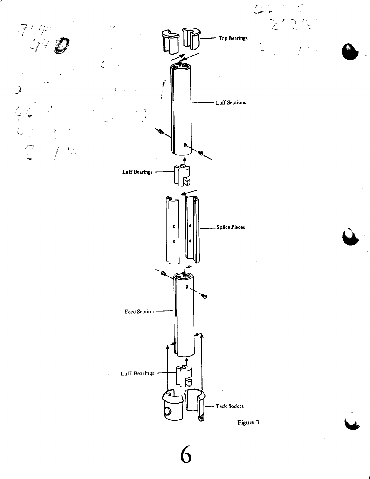
1.
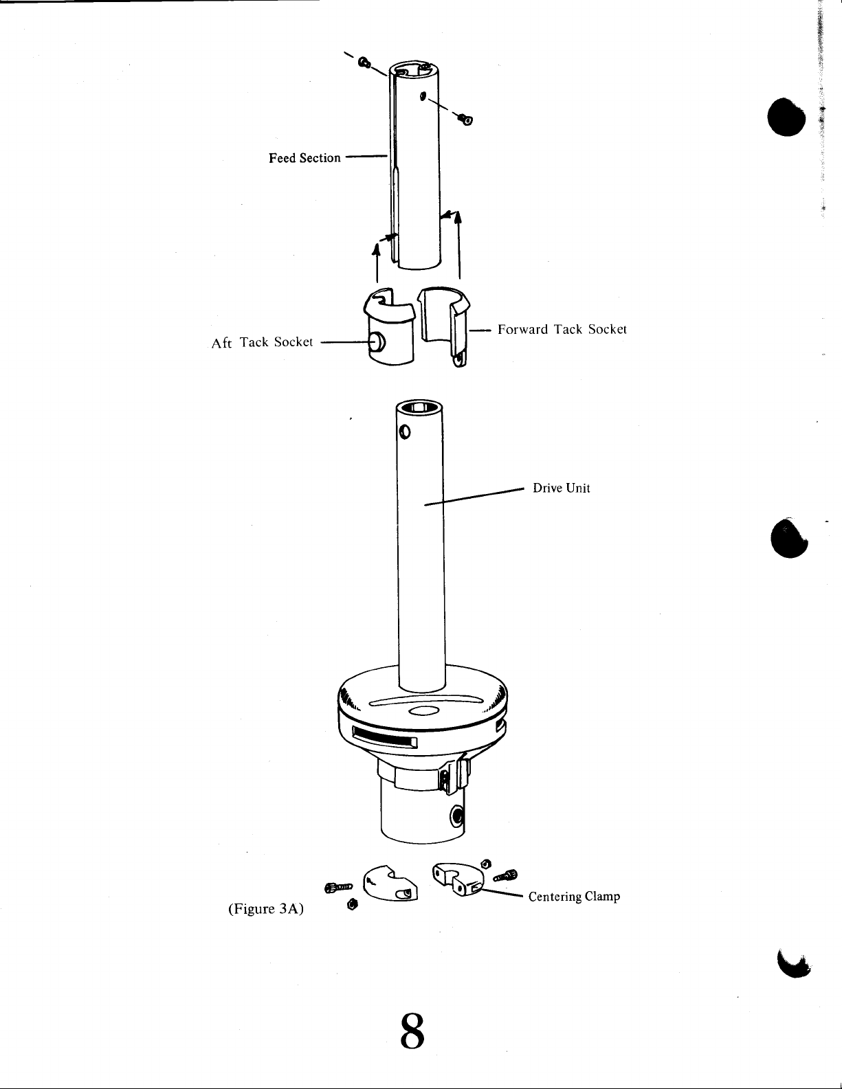
NOTE: Make sure that Luff Bearing
is Installed in Feed Section
just above the Aft Tack Socket.
Locate the Feed
identified
end.
EXTRUSION
from
which
the Luff
has its
Sections. The
luff
as
the
Section
section
ASSEMBLY
Feed
Section
grooves
machined
open
ar
can be
its
lower
Slide the Feed
Section
through the
headstay
of the
end
Take
2.
one of the
above the Feed
Take two
3.
headstay.
Line up the
4.
in the
upper
them with
larger hole in
Take
one
it down
Feed
Section.
Luff Bearing
Repeat
6.
Rivet
another
step
the top
Section over rhe top
is
designed
inside
its
until
Luff
Section assembly
Section.
the
of
black
Splice Pieces and mate them rogether
so
of the
lower
plastic
thar
a standard
secion. Slide this
is
end
Luff Bearings
Insert it into
Insert them into the top
two holes in the
end of
hammer.
a
the Feed
the
of
over the
Luff
Splice Pieces that
Rivet the
the headstay
onto
set
of splice
5 until the top
the Feed
Note
Sections and slide
pair
that the head
Section locking the
Luff Section to rhe
pieces
of
of the headstay.
the
of
with
even
(determined
of the Feed
headstay;
marine wire
section
the
mark
in
and twist
the rop
of
the
Section.
lower
end fitting
all the
which
step
6
it
Feed
of Splice Pieces with
Section. Insert a rivet into
the rivet
of
it
over
are now
Splice
the
sticking
should
Pieces
top
our
Splice Pieces.
insert
the
and
into
Luff
it into
the top
Section
the top
the
of
section.
assembly
end first.
The
will pass
way
locates
page
on
down
the
5).
the
lower
onto the headstay
Section.
pair
as a
rhe two
each hole
around the
larger
holes
and fasten
sit inside the
into place.
of the headstay.
the
of
of
comes within
top
Twist
the
of the
anorher
Luff
Section.
6'
Feed
Slide
of
The last
7.
will
the
After
over
section
be
1%" berween
wire terminal (Figure
cutting this
the
top
ached to the
tance
between
It/2". After riveting,
To
complete
Bearing into
glued in place
irit
.i.
.i.
.'..r
'i
*:i::i i ii
i
iii1,,
i"i
:: ::. i::i !:!
i :,,, :'i i:'.:l'1.:.*
:::$1
l..j
,.;i:i.r...'1i,,
1;
:"'
'i.:
i;
j'
!'
i... l..i
i-:iL".,'.lr:i llii+.':i::
j'i:
;"i;
to
be assembled
the top
upper
the
of
headstay
next lower
the
top
of
insert
the
Luff
Section assembly, inserr the two
the top
with
ii'ii
'!'.,',".i
of
the silicone
:
i
i':
i-
','r
::
.:. i:.,
::::l
should
the
of
2).
Luff Section
and rivet it
secion.
the
Before
Luff
a Luff
the
section
sealanr
i::i
r
i i
i;
i:-.
'
''
be cut so thar
Luff
Section assembly
(be
sure to
to the
riveting,
Section and
Bearing
into the rop
Splice Pieces
the
when
deburr
check to
end
of
of the
rhe
make
the
halves
assembly. The Top Bearing
provided.
assembled
and the
bottom
edges),
which
sure the
wire
terminal
Luff
Section.
the
of
should
there
slide it
are
att-
dis-
Top
be
of
is
Feed
Section
,vr /r-,
rack Socket
Art
+J
Crlt fi?
tlu-
Forward rack Socket
Drive
Unit
(Figure3A)
*(\w
O
s
8
-centeringclamP
\*
 Loading...