


7
Network Connections
The tablet PC has an RJ-45 network jack. Network tablet PC
models also have an internal NIC (network interface card),
preinstalled network drivers, and a network cable.
The tablet PC can be connected to a network whether or not the
internal modem is connected to a telephone line.
If your tablet PC is connected to a network, you may want to
confer with your network administrator before changing network
settings.
The tablet PC supports network speeds up to 10 Mbps when
connected to a 10BaseT network and 100 Mbps when connected
to a 100BaseTX network.
Hardware Guide 7–1
Network Connections
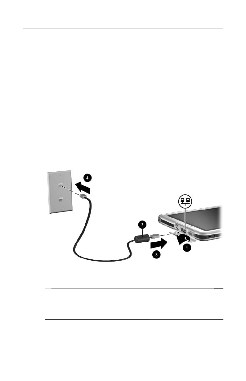
Connecting the Network Cable
A network cable has an 8-pin RJ-45 network connector at each
end and may contain noise suppression circuitry, which prevents
interference with TV and radio reception.
1. To access the tablet PC RJ-45 network jack 1, open the upper
panel of the tablet PC.
2. Orient the end of a network cable with noise suppression
circuitry 2 toward the tablet PC.
3. Plug the network cable into the tablet PC RJ-45 network
jack 3.
4. Plug the other end of the cable into the network RJ-45
jack 4.
Connecting a network cable
WARNING: To reduce the risk of electric shock, disconnect
Å
the network cable before accessing an internal compartment of the
tablet PC. Internal compartments include the memory and mini PCI
compartment and the hard drive bay.
7–2 Hardware Guide
Network Connections
Turning a Network Connection Off
and On
To conserve power, turn off a network connection you are not
using.
■ To turn off a network connection, log off the network, then
disconnect the network cable.
■ To turn on a network connection, connect the network cable,
then log on to the network.
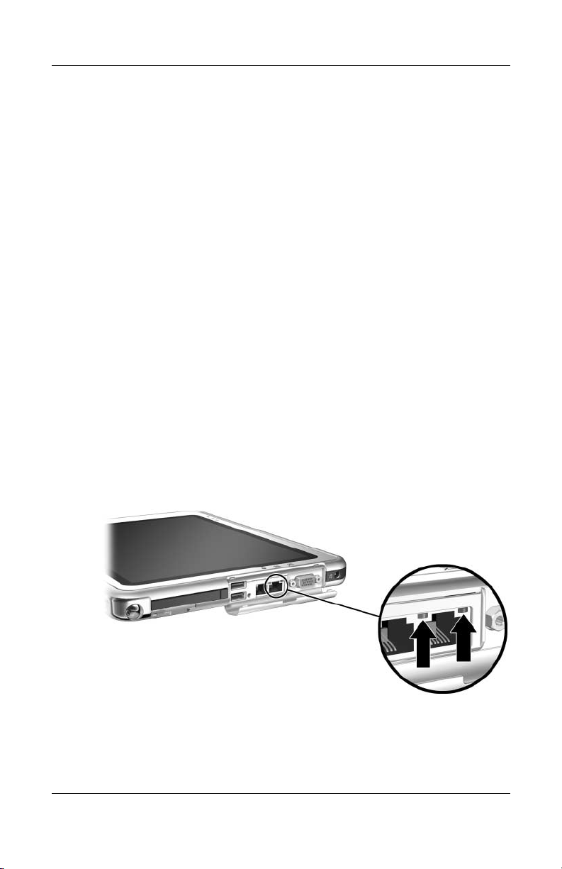
Using the LAN Connection Lights
The 2 LAN connection lights indicate the status of a network
connection:
■ Both lights off: The tablet PC is not connected to a LAN.
■ Both lights on: The tablet PC is connected to a LAN with
a 100 Mbps link.
■ Green light on and yellow light off: The tablet PC is
connected to a LAN with a 10 Mbps link.
Identifying the LAN connection lights
Hardware Guide 7–3

Network Connections
Accessing the Network at Startup
To connect to a PXE (Preboot eXecution Environment) or RPL
(Remote Program Load) server during startup, you must respond
to the Network Service Boot prompt each time you want to
connect to the server as the tablet PC starts or restarts.
To set the tablet PC to display the Network Service Boot prompt
each time it is started or restarted, you must enable the internal
NIC for startup.
Enabling a NIC for Startup
An internal NIC is enabled for startup in the Setup utility.
1. To open the Setup utility, turn on or restart the tablet PC.
While the HP logo is displayed and a cursor is flashing in
the upper right corner of the screen, press the esc button
on the tablet PC or press
2. To change the language, select Advanced > Languages.
❏ To navigate and select without using an optional
keyboard, rotate the jog dial to scroll and press the jog
dial inward to select.
❏ To navigate and select using an optional keyboard, use
the arrow and
3. Select Advanced menu > I/O Device Configuration, then
enable PXE/Remote Boot.
4. To save your preference and exit the Setup utility, select
File > Save Changes and Exit, then follow the instructions
on the screen.
Your preference is set as you exit the Setup utility and is in effect
when the tablet PC restarts.
F10 on an optional keyboard.
enter keys.
7–4 Hardware Guide

Network Connections
Responding to a Network Service Boot
Prompt
After the internal NIC has been enabled for startup, the Network
Service Boot prompt is displayed very briefly in the lower right
corner of the screen each time the tablet PC is started or restarted.
To connect to a network by responding to the prompt, use either
of the following procedures:
■ Press the tab button on the tablet PC.
■ Press F12 on an optional keyboard. To press F12 on the
tablet PC keyboard, press
Fn+F11/F12.
Finding Wireless LAN Information
The tablet PC supports wireless LAN provided through a
mini PCI board, a PC Card, or an SD Card. A wireless LAN
PC Card or an SD Card is optional. A wireless mini PCI board
may be preinstalled.
■ Information about using a preinstalled wireless LAN board is
provided on the Documentation Library Wireless LAN CD
included with your tablet PC.
■ Information about the Bluetooth wireless option is provided
on the Documentation Library Bluetooth CD included with
your tablet PC.
■ Information about Microsoft’s Wireless LAN configuration
utility is available in the Help & Support Center, which is
accessible from the Start Menu.
If you purchase a wireless device as an option, documentation
about the device is included with the option.
Hardware Guide 7–5

External Device Connections
Standard Device
The jacks and connectors described in this guide support standard
external devices.
■ For information about which jack or connector to use, refer to
the documentation included with the device.
■ For information about installing or loading any software
required by the device, refer to the device documentation, the
operating system Help files, or the device manufacturer’s
Web site.
To connect a standard external device to the tablet PC:
1. If you are connecting a powered device, be sure the device is
turned off.
2. Connect the device to a jack or connector on the tablet PC.
3. If you are connecting a powered device, plug the device
power cord into a grounded electrical outlet.
4. Turn on the device.
8
If a properly connected display device does not display an image,
✎
try pressing the Q menu button > Internal and External item or
External Only item to switch the image to the new device.
To disconnect a standard external device from the tablet PC, turn
off the device (if it is powered), then disconnect the device from
the tablet PC.
Hardware Guide 8–1
External Device Connections
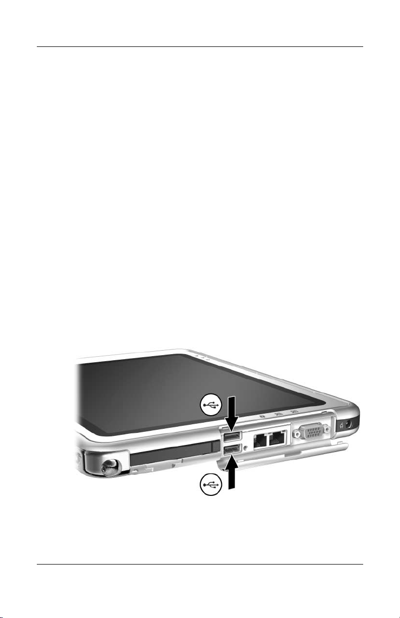
USB Device
USB is a hardware interface that can be used to connect external
devices such as a USB keyboard, mouse, drive, printer, scanner,
or hub to the tablet PC or an optional Docking Station.
A USB device functions in the system in the same way as a
comparable non-USB device. The USB connectors support
USB 2.0- or 1.1-compliant devices.
A USB hub is a connecting device that can be powered or
unpowered. USB hubs can be connected to a USB connector on
the tablet PC or on an optional Docking Station or to other USB
devices. Hubs support varying numbers of USB devices and are
used to increase the number of USB devices in the system.
■ Powered hubs must be connected to external power.
■ Unpowered hubs must be connected either to a USB
connector on the tablet PC or to a port on a powered hub.
Some USB devices may require additional support software,
which is usually included with the device. For software
information about a specific device, refer to the documentation
included with the device.
Identifying the 2 USB connectors on the tablet PC
8–2 Hardware Guide
External Device Connections
Tablet PC Keyboard
A tablet PC keyboard, which includes a numeric keypad, can be
used with the tablet PC.
For information about using the tablet PC keyboard pointing
device, keypad, and
and Keyboards” chapter, “Tablet PC Keyboard” section.
The tablet PC can be attached or detached from the keyboard
while it is on, off, in Standby, or in Hibernation.
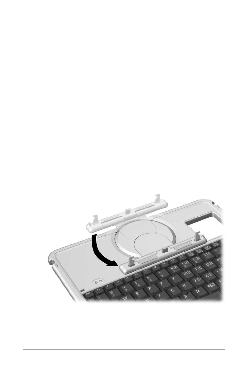
Attaching the Tablet PC to the Keyboard
To attach the tablet PC to the keyboard:
1. Place the keyboard on a flat surface with the keyboard keys
facing you.
2. Rotate the attachment features on the rotation disk toward the
keyboard.
F11/F12 key, see the “Pen, Command Controls
Rotating the attachment features toward the keyboard
Hardware Guide 8–3
External Device Connections
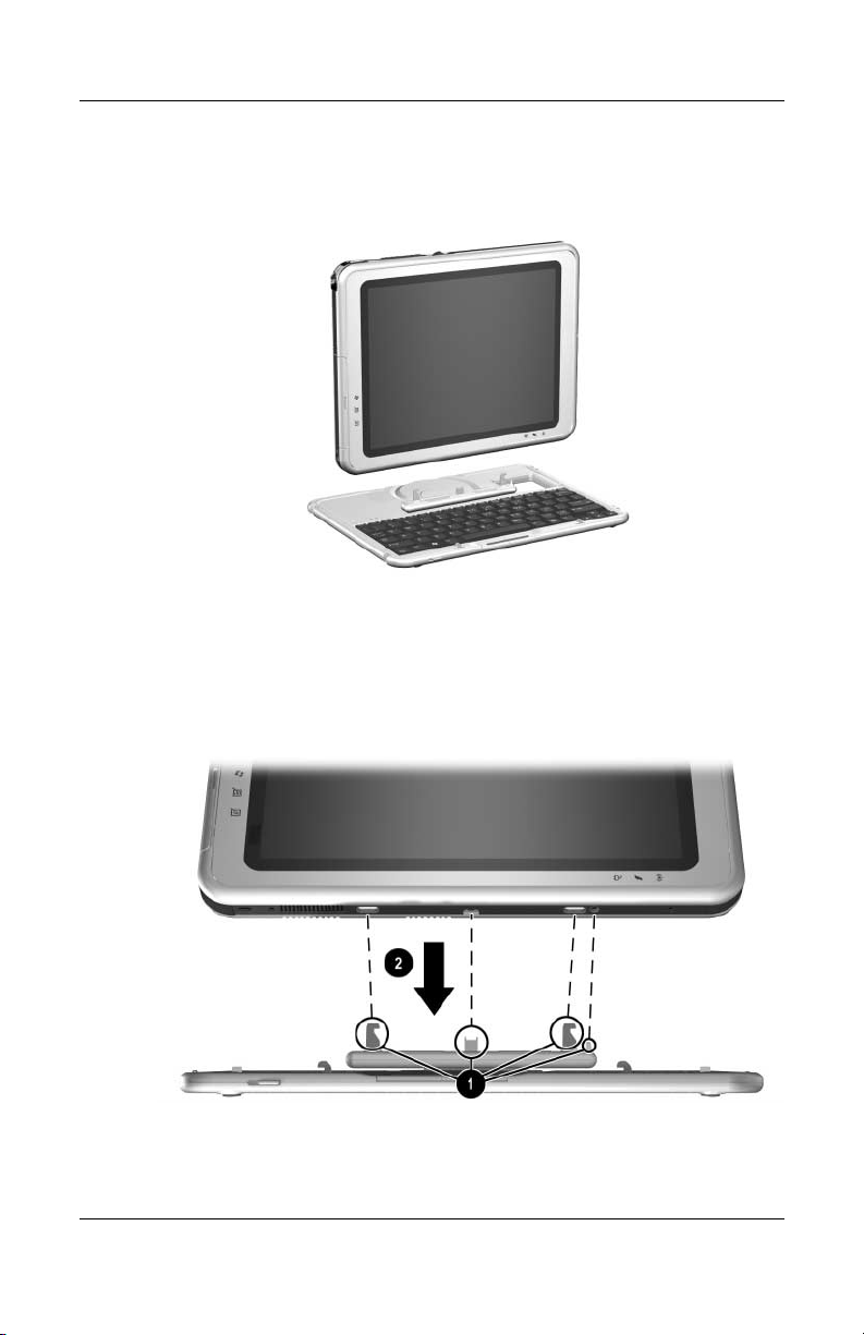
3. Position the tablet PC horizontally above the keyboard, with
the front of the tablet PC facing the keyboard.
Positioning the tablet PC above the keyboard
4. Align the 4 slots on the tablet PC with the keyboard
connector, alignment key, and 2 keyboard hooks on the
keyboard 1, then press the tablet PC downward until it
snaps into place 2.
Attaching the tablet PC to the keyboard
8–4 Hardware Guide
External Device Connections
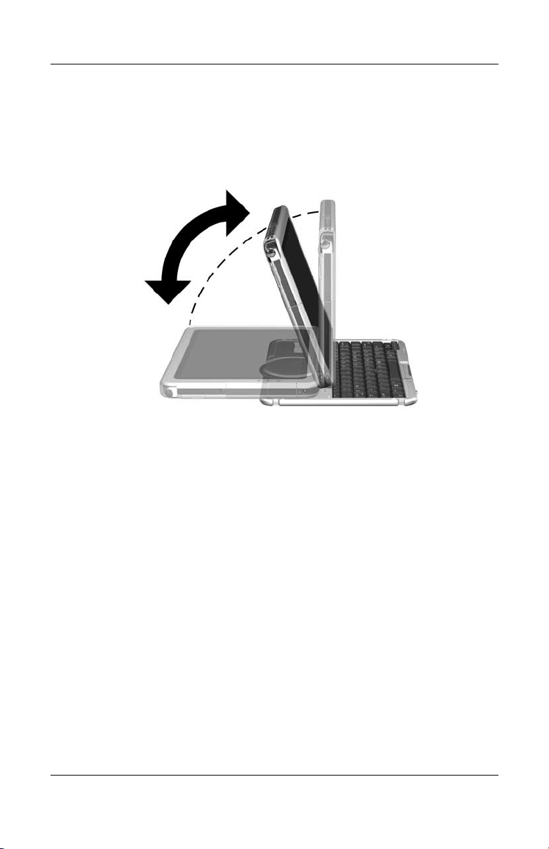
Adjusting the Tablet PC and Keyboard
To tilt the tablet PC screen to a comfortable viewing angle, push
gently on the top of the tablet PC.
Tilting the tablet PC on the keyboard
Hardware Guide 8–5
External Device Connections
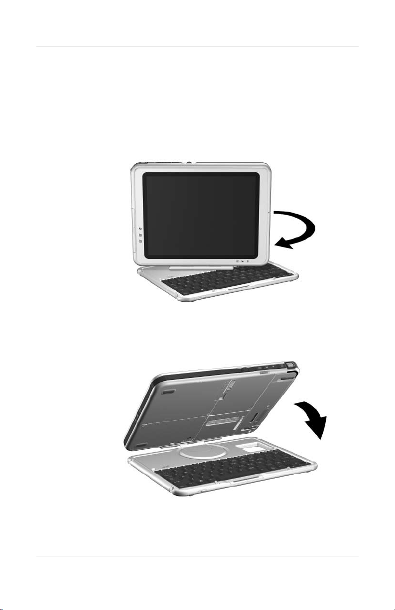
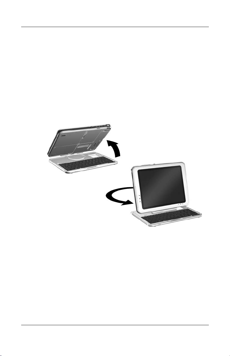
Closing the Tablet PC and Keyboard
To close the tablet PC and keyboard as you would close the
display on a standard notebook:
1. Rotate the tablet PC clockwise until it snaps into place facing
away from the keyboard.
Rotating the tablet PC toward the back of the keyboard
2. Tilt the tablet PC downward onto the keyboard.
Closing the tablet PC and keyboard
8–6 Hardware Guide
External Device Connections
Transporting the Tablet PC and Keyboard
If you are transporting the tablet PC and keyboard while they are
not attached, be sure the rotation disk is in the default position.
(The attachment features are at the rear of the tablet PC and the
HP logo is right side up when you are facing the keyboard.)
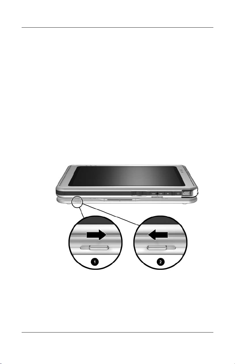
If you are transporting the tablet PC and keyboard while they are
attached, you may want to use the keyboard latch. The keyboard
latch locks the tablet PC to the keyboard while the tablet PC and
keyboard are closed.
■ To lock the tablet PC to the keyboard while the tablet PC is
closed, slide the keyboard latch to the right 1.
■ To release the tablet PC from the closed position, push the
keyboard latch to the left, then slide and hold the latch toward
the left as you open the tablet PC 2.
Using the keyboard latch
Hardware Guide 8–7
External Device Connections
Detaching the Tablet PC from the Keyboard
To detach the tablet PC from the keyboard:
1. If the tablet PC is closed, open the tablet PC, then rotate the
tablet PC so the screen is facing the keyboard in the notebook
position.
If the tablet PC does not open easily from the keyboard, it
may be secured to the keyboard with the keyboard latch. For
release instructions, see the “Transporting the Tablet PC and
Keyboard” section, earlier in this chapter.
Opening the tablet PC to the notebook position
8–8 Hardware Guide
External Device Connections
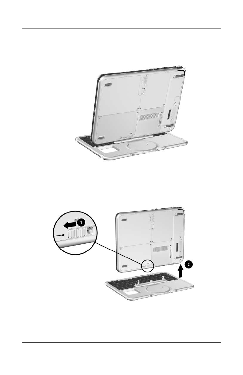
2. Rotate the tablet PC and keyboard so the back of the
tablet PC and the keyboard are facing you.
Positioning the tablet PC and keyboard to detach the tablet PC
3. To detach the keyboard, slide and hold the attachment release
switch 1 on the tablet PC as you lift the tablet PC away from
the keyboard 2.
Detaching the tablet PC from the tablet PC keyboard
Hardware Guide 8–9
External Device Connections
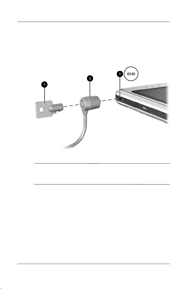
Cable Lock
Loop the cable around a secure object, then insert the cable
lock key 1 into the security cable lock 2. Then insert the
cable lock into the security cable slot 3 on the tablet PC.
Connecting an optional cable lock
The purpose of security solutions is to act as a deterrent. These
✎
solutions do not prevent the product from being mishandled or
stolen.
8–10 Hardware Guide

Additional Hardware Options
Obtaining Upgrades
To order or learn more about optional hardware upgrades and
accessories, visit the HP Web site at
hardware upgrade area is English only. Or, refer to the Wor ld wi de
Telephone Numbers booklet, included in English only with the
tablet PC, to contact an HP-authorized dealer, reseller, or service
provider.
For information about obtaining and installing software updates
and upgrades, refer on this CD to the Software Guide.
Using a PC Card
A PC Card is a credit card–sized accessory designed to conform
to the standard specifications of the Personal Computer Memory
Card International Association (PCMCIA). The tablet PC
supports both 32-bit CardBus and 16-bit PC Cards.
A PC Card can be used to add modem, sound card, memory,
storage, wireless communication, or digital camera functions to
the tablet PC. A PC Smart Card Reader or a biometric
identification PC Card can add security.
http://www.hp.com. The
9
The purpose of security solutions is to act as a deterrent. These
✎
solutions do not prevent the product from being mishandled or
stolen.
Hardware Guide 9–1

Additional Hardware Options
Selecting a PC Card
A Type I or Type II PC Card can be used. A Type III PC Card will
not fit into the PC Card slot of the tablet PC. (Types I, II, and III
PC Cards vary by thickness, with Type III being the thickest.)
Zoomed video cards are not supported.
Configuring a PC Card
CAUTION: If you install all of the software or any of the enablers
Ä
provided by a PC Card manufacturer, you may not be able to use other
PC Cards. If you are instructed by the documentation included with
a PC Card to install device drivers:
■ Install only the device drivers for the Microsoft Windows XP
Tablet PC Edition operating system.
■ Do not install other software, such as card services, socket services,
or enablers, that may also be supplied by the PC Card
manufacturer.
9–2 Hardware Guide
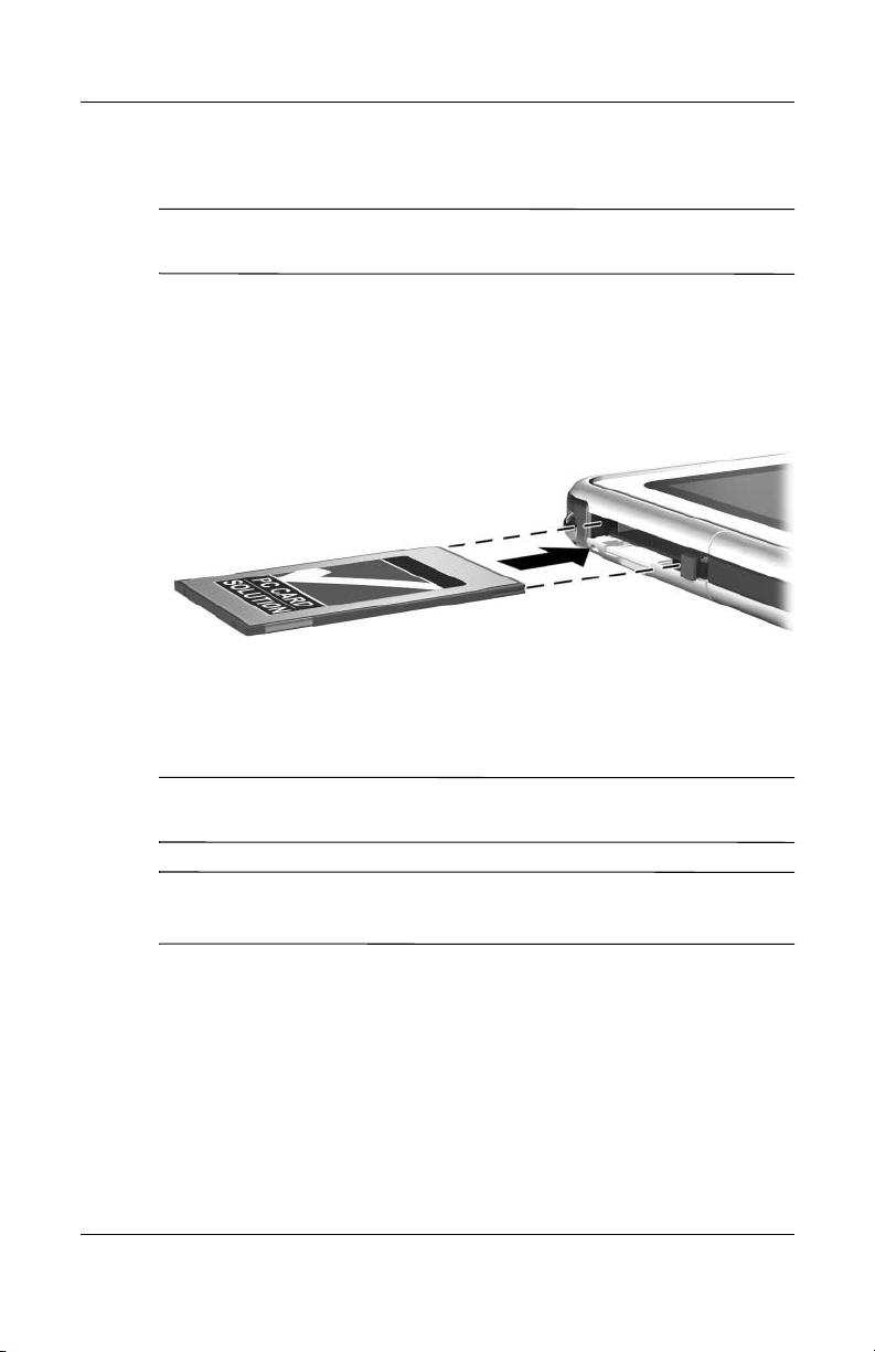
Inserting a PC Card
CAUTION: To prevent damage to the PC Card connectors, use minimal
Ä
force when inserting a PC Card into the PC Card slot.
1. Hold the PC Card label-side up with the connector facing
the tablet PC.
2. Gently push the card into the PC Card slot until the card
is seated.
Inserting a PC Card
Additional Hardware Options
Stopping and Removing a PC Card
CAUTION: To prevent loss of work or an unresponsive system, stop a
Ä
PC Card before removing it.
An inserted PC Card uses power even when it is not in use. To
✎
conserve power, stop a PC Card when you are not using it.
1. Close all applications and complete all activities that are
supported by the PC Card.
2. To stop a PC Card, select the system tray icon for Safely
Remove Hardware, then follow the instructions on the screen.
(To display the Safely Remove Hardware icon, select the
system tray icon for Show Hidden Icons.)
Hardware Guide 9–3

Additional Hardware Options
3. To release the PC Card, press the PC Card eject button 1.
4. Gently pull out the PC Card 2.
Removing a PC Card
Using an SD Card
An SD Card is smaller than a PC Card, but can add similar
functions to the tablet PC system. Most commonly, an SD Card is
used to add backup, storage, wireless network, fax/modem, or
cellular telephone functions.
When using an SD Card, HP recommends that you connect the
system to external power whenever possible. Some SD Cards use
large amounts of power and can quickly drain a battery pack.
CAUTION: To prevent loss of work or damage to an SD Card:
Ä
■ Do not save your work to an SD Card unless the tablet PC is
connected to external power or you are certain that the battery
pack has enough charge remaining to complete the operation.
■ Do not shut down the tablet PC or remove the SD Card until all
activities supported by the card are complete.
9–4 Hardware Guide

Configuring an SD Card
If an SD Card manufacturer instructs you to install card-specific
drivers, be sure to install only the drivers supported by the
Windows XP Tablet PC Edition operating system. If you are
unsure of driver compatibility, contact the SD Card manufacturer.
Inserting an SD Card
CAUTION: To prevent damage to the SD Card connectors, use minimal
Ä
force when inserting an SD Card into the SD Card slot.
1. Hold the SD Card label-side up with the connector facing
the tablet PC.
2. Gently push the card into the SD Card slot until the card is
seated.
Additional Hardware Options
Inserting an SD Card
Hardware Guide 9–5
Additional Hardware Options
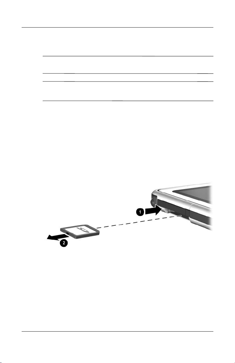
Stopping and Removing an SD Card
CAUTION: To prevent loss of work or an unresponsive system, stop an
Ä
SD Card before removing it.
An inserted SD Card uses power even when it is not in use. To
✎
conserve power, stop an SD Card when you are not using it.
1. Close all applications and complete all activities that are
supported by the SD Card.
2. To stop an SD Card, select the system tray icon for Safely
Remove Hardware, then follow the instructions on the screen.
(To display the Safely Remove Hardware icon, select the
system tray icon for Show Hidden Icons.)
3. To release the SD Card, press inward on the SD Card 1.
4. Gently pull out the SD Card 2.
Removing an SD Card
9–6 Hardware Guide

Additional Hardware Options
Increasing Memory
You can increase the amount of RAM (random access memory)
in the tablet PC with an optional PC Card or with an optional
memory module.
The tablet PC has one user-accessible memory slot. The slot
supports a PC133-compliant 128-megabyte, 256-megabyte, or
512-megabyte memory module.
Displaying Memory Information
When the amount of RAM in the system increases, the operating
system increases the hard drive space reserved for the
hibernation file.
If you experience problems with Hibernation after increasing
RAM, verify that your hard drive has enough free space for the
larger hibernation file.
■ To display the amount of RAM in the system:
Select Start > Control Panel > Performance and
Maintenance icon > System icon > General tab.
■ To display both the amount of free space on your hard drive
and the amount of space required by the hibernation file:
Select Start > Control Panel > Performance and
Maintenance icon > Power Options icon > Hibernate tab.
Hardware Guide 9–7

Additional Hardware Options
Removing or Inserting a Memory Module
WARNING: To prevent exposure to electric shock, work only in the
Å
memory and mini PCI compartment during this procedure. The hard
drive bay and the memory and mini PCI compartment are the only
user-accessible internal compartments on the tablet PC. All other areas
that require a tool to access should be opened only by an HP-authorized
service provider.
WARNING: To prevent exposure to electric shock and damage to the
Å
tablet PC, shut down the tablet PC, unplug the power cord, and remove
the battery pack before installing a memory module.
CAUTION: To prevent electrostatic discharge from damaging electronic
Ä
components: Discharge static electricity from yourself by touching a
grounded metal object before beginning this procedure. For more
information about preventing electrostatic damage, refer on this CD to
the Regulatory and Safety Notices guide.
1. Be sure that you have followed the instructions in the
preceding warnings and caution.
If you are not sure whether the tablet PC is off or in
Hibernation, slide and release the power switch. If your
work returns to the screen, save your work, exit all
applications, then shut down the tablet PC.
2. Disconnect all external devices connected to the tablet PC.
3. Disconnect the power cord.
4. Remove the battery pack.
5. If the tablet PC keyboard is attached to the tablet PC, detach
the keyboard.
9–8 Hardware Guide

Additional Hardware Options
6. Turn the tablet PC front side down.
7. Remove the two memory and mini PCI compartment
retaining screws 1.
8. Slide, lift, then remove the memory and mini PCI
compartment cover 2.
Opening the memory compartment
Hardware Guide 9–9

Additional Hardware Options
9. Remove or insert the memory module.
To remove a memory module:
a. Release the retention clips on each side of the memory
module 1. (The memory module tilts upward.)
b. Grasp the edges of the memory module, then gently pull
it out of the memory slot 2.
c. To protect a removed memory module, place it in an
electrostatic-safe container.
Removing a memory module
9–10 Hardware Guide

Additional Hardware Options
To insert a memory module:
a. Align the keyed (notched) edge of the memory module
with the keyed area in the memory slot 1.
b. Press the memory module into the slot from a 45-degree
angle until it is seated 2.
c. Push the memory module downward until the retention
clips snap into place 3.
Inserting a memory module
Hardware Guide 9–11
Additional Hardware Options
10. Align the tabs on the memory compartment cover with the
cover slots on the tablet PC 1, then press downward on
the cover until it is seated.
11. Reinsert the two retaining screws that secure the memory and
mini PCI compartment cover to the tablet PC 2.
Replacing the memory compartment cover
9–12 Hardware Guide

Maintenance, Shipping and
Maintaining Software
HP recommends that you:
■ Install all software updates as they become available. For
instructions, refer on this CD to the Software Guide,
“Software Updates and Restorations” chapter.
■ Install and use virus protection software. Antivirus software
can be purchased from most computer or electronics retailers.
■ Back up your work and system software frequently.
❏ For information about using the operating system backup
utility, select Start > Help and Support > Performance
and Maintenance topic. In the upper left pane of
the Performance and Maintenance window, select the
Backing Up Your Data check box.
❏ For information about selecting optional backup software
or hardware, consult with your authorized HP dealer,
reseller, or service provider.
10
Travel
Hardware Guide 10–1

Maintenance, Shipping and Travel
Protecting Hardware
To protect and prolong the performance of your hardware,
observe the following cautions.
CAUTION: To prevent damage to your hardware or loss of work:
Ä
■ Carry and store the tablet PC in the portfolio or an optional
Executive Portfolio.
■ Do not place anything on top of the tablet PC, even when it is in a
portfolio.
■ Use the tablet PC only on solid surfaces and in open areas. Do not
allow a hard surface, such as an adjoining optional printer, or a
soft surface, such as carpet, clothing, or bedding, to block the vent.
■ Protect the tablet PC from liquids and excessive moisture.
■ Do not expose the tablet PC to direct sunlight, extreme
temperatures, or ultraviolet light for extended periods of time.
■ Keep all hard drives and diskettes away from magnetic fields.
Magnetic fields can corrupt data stored on hard drives and
diskettes.
■ If the tablet PC will be unused for one week or more, shut it down.
■ If the tablet PC will be disconnected from external power for more
than one month, shut down the tablet PC and remove the battery
pack. For information about storing the battery pack, see
Chapter 3,“Battery Packs.”
10–2 Hardware Guide

Using Portfolios
To protect the tablet PC screen, HP recommends that you use or
transport the tablet PC with a portfolio attached. A slim portfolio
that protects the tablet PC or the tablet PC attached to an optional
keyboard is included with the tablet PC.
An optional leather Executive Portfolio that provides additional
protection, has
additional items is available in most regions.
To obtain the Executive Slimline or Workstation Portfolio, refer
to the Worldwide Telephone Numbers booklet included in English
only with the tablet PC to contact your authorized HP dealer,
reseller, or service provider.
slots for business cards, and accommodates
Attaching a Portfolio
When you are using only the tablet PC, press the 2 tabs on the
portfolio into the 2 universal attachment slots on the tablet PC.
Maintenance, Shipping and Travel
Identifying the universal attachment slots on the tablet PC
Hardware Guide 10–3

Maintenance, Shipping and Travel
When you are using the tablet PC attached to the tablet PC
keyboard, press the 2 tabs on the portfolio into the 2 universal
attachment slots on the keyboard.
Identifying the universal attachment slots on a tablet PC keyboard
10–4 Hardware Guide
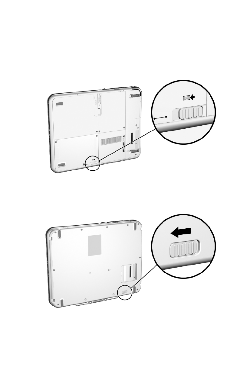
Detaching a Portfolio
To release a portfolio from the tablet PC, slide an hold the
attachment release switch on the tablet PC.
Sliding the attachment release switch on the tablet PC
To release a portfolio from the tablet PC keyboard, slide and hold
the attachment release switch on the tablet PC keyboard.
Maintenance, Shipping and Travel
Sliding the attachment release switch on the tablet PC keyboard
Hardware Guide 10–5

Maintenance, Shipping and Travel
Cleaning Hardware
WARNING: To prevent electric shock or damage to components,
Å
do not attempt to clean the tablet PC until you:
■ Shut down the tablet PC.
■ Disconnect the tablet PC from external power.
■ Disconnect all powered external devices from the tablet PC.
CAUTION: Do not spray liquids on the tablet PC. Household solvents
Ä
can permanently damage tablet PC surfaces, and any liquid can
damage the internal components of the tablet PC or an optional
keyboard.
Cleaning the Screen
To remove smudges and lint, clean the screen with a soft, lint-free
cloth dampened with water or a glass cleaning liquid. Antistatic
screen cleaner or premoistened antistatic wipes may also be used.
10–6 Hardware Guide

Maintenance, Shipping and Travel
Cleaning a Tablet PC Keyboard
Dust, lint, and other debris can affect the performance of
an optional tablet PC keyboard. To prevent sticking or
nonfunctioning keys, clean the keyboard frequently using a
can of compressed air with a straw extension. Blow the
compressed air around the base of each key.
To clean the key surfaces, use a soft, damp, lint-free cloth.
Using a household vacuum cleaner to clean the keyboard may
✎
deposit, rather than remove, debris.
Cleaning a tablet PC keyboard with a can of compressed air
Hardware Guide 10–7

Maintenance, Shipping and Travel
Replacing Hardware
Replacing the System Hard Drive
The system hard drive is the hard drive in the hard drive bay.
Remove the system hard drive only for repair or replacement.
CAUTION: To prevent an unresponsive system and loss of work:
Ä
■ Shut down the tablet PC before removing the system hard drive.
Do not remove the system hard drive while the tablet PC is powered
on, in Standby, or in Hibernation.
■ To verify that the tablet PC is off and not in Hibernation, slide and
release the power switch. If your work returns to the screen, save
your work, exit all applications, then shut down the tablet PC.
10–8 Hardware Guide

Maintenance, Shipping and Travel
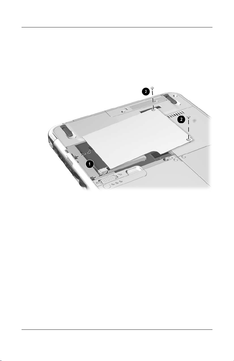
1. Save your work, then shut down the tablet PC.
2. Turn the tablet PC front side down.
3. Remove the 2 hard drive bay cover retaining screws 1.
4. Slide, lift, then remove the hard drive bay cover 2.
Removing the hard drive bay cover
CAUTION: The connector pins on the hard drive are designed to
Ä
support only the minimal insertions or removals that may be required for
repair or replacement. To prevent damage to the hard drive connectors,
be careful not to bend them while removing the hard drive.
Hardware Guide 10–9

Maintenance, Shipping and Travel
5. To remove the hard drive, gently disengage the drive
connectors 1 by sliding the hard drive toward the lower
edge of the tablet PC.
6. Remove the drive from the bay 2.
Removing a system hard drive from the hard drive bay
10–10 Hardware Guide

Maintenance, Shipping and Travel
7. To insert the replacement hard drive, lower the drive into the
hard drive bay 1, then slide the connectors on the hard drive
toward the connectors in the bay 2 until the connectors
engage and the drive is seated.
Inserting a system hard drive into the hard drive bay
Hardware Guide 10–11
Maintenance, Shipping and Travel
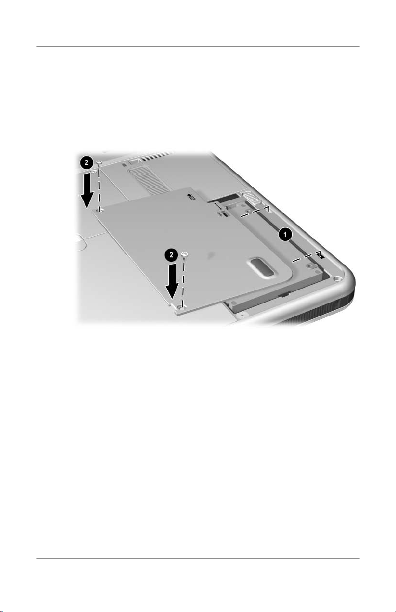
8. Align the tabs on the hard drive bay cover with the cover
slots on the tablet PC 1, then press downward on the
cover until it is seated.
9. Reinsert the 2 retaining screws that secure the cover to the
tablet PC 2.
Replacing the hard drive bay cover
10–12 Hardware Guide

Maintenance, Shipping and Travel
Replacing a Pointing Stick Cap
Two pointing stick replacement caps are included with an
optional tablet PC keyboard. To replace a worn pointing
stick cap:
1. If the keyboard is attached to the tablet PC, shut down the
tablet PC.
2. Gently pull off the used pointing stick cap.
3. Push a replacement cap into place.
Replacing the pointing stick cap
Hardware Guide 10–13

Maintenance, Shipping and Travel
Preparing the Tablet PC for
Shipping or Travel
1. Back up your work.
2. Remove a PC Card or SD Card.
3. Undock the tablet PC from an optional Docking Station.
4. Turn off, then disconnect all optional external devices such as
headphones or an External MultiBay. (It is not necessary to
detach the tablet PC from the tablet PC keyboard.)
5. Shut down the tablet PC.
6. If the tablet PC will be disconnected from an external power
source for more than one month, shut down the tablet PC,
remove the battery pack, and store the battery pack in a cool,
dry place.
7. If you are shipping the tablet PC, insert it into a portfolio,
place it in the original packing box or similar protective
packaging, and label the package “FRAGILE.”
10–14 Hardware Guide

Maintenance, Shipping and Travel
Traveling with the Tablet PC
Checklist for Travelers
■ Take along a backup of your work. Do not pack the backup
with the tablet PC.
■ Carry the tablet PC with you. Do not check it with
your luggage.
■ If you will have access to an optical drive, you may want to
take along the Documentation Library CD. If not, HP
suggests that you print and take with you the “Contacting
HP” section later in this chapter.
■ Do not expose the tablet PC, a hard drive, or a diskette to a
magnetic security detector.
❏ The security device that examines carry-on items placed
on a conveyer belt uses x-rays and is safe for the
tablet PC and all drive media.
❏ The walk-through security device and handheld
security wands are magnetic and may damage the
tablet PC, a hard drive, or a diskette.
■ If you plan to use the tablet PC during a flight, check with the
airline in advance. In-flight tablet PC use is at the discretion
of the airline.
■ If you expect to encounter climatic extremes, see the
“Specifications” chapter, “Tablet PC Operating
Environment” section.
Hardware Guide 10–15

Maintenance, Shipping and Travel
■ If you are traveling internationally:
❏ If you plan to use an internal modem, review Chapter 6,
“Internal Modem” for information about using adapters
and country configurations. You may want to print and
take with you the “Solving Travel Connection Problems”
section of that chapter if you are not bringing the
Documentation Library CD.
❏ Check the computer-related customs regulations for each
country on your itinerary.
❏ Consult with an electronics retailer or an HP authorized
dealer, reseller, or service provider about power cord and
adapter requirements for each location in which you plan
to use the tablet PC. (Voltage, frequency, and plug
configurations vary.) To contact an HP-authorized dealer,
reseller, or service provider near you, refer to the
Worldwide Telephone Numbers booklet included in
English only with the tablet PC.
WARNING: To reduce the risk of electric shock, fire, or damage to the
Å
equipment, do not attempt to run the tablet PC with a voltage converter
kit sold for appliances.
Contacting HP
Getting Help from the Internet
If you have Internet access, you can resolve most problems that
may arise while traveling with the tablet PC by using HP Help
and Support.
HP Help and Support provides links to specific areas of the HP
Web site (
■ Obtain all documentation included with your tablet PC as
■ Initiate an online service event with an HP support specialist.
10–16 Hardware Guide
http://www.hp.com) where you can:
well as other information about your tablet PC such as
specifications, white papers, and customer advisories.

Maintenance, Shipping and Travel
■ Download the latest drivers, utilities, and other software
updates for your tablet PC.
■ Subscribe to the HP Support Software CD.
To access these links and descriptions of the options they provide,
select Start > HP Help and Support. The HP Help and Support
menu is displayed in the left panel.
Not all links are available worldwide, and most sites are available
in limited languages.
Getting Help Without Using the Internet
If you need help and cannot access the Internet:
■ To obtain troubleshooting information:
❏ Refer on this CD to the Troubleshooting guide.
❏ Refer to the “Solving Problems” chapter in the printed
Startup Guide included with the tablet PC.
■ To obtain a list of worldwide Technical Support telephone
numbers:
❏ Select Start > Control Panel > Performance and
Maintenance icon > System icon. Then, near the lower
edge of the System Properties window, select the Support
Information button.
Refer to the printed Worldwide Telephone Numbers booklet
included in English only with the tablet PC.
Hardware Guide 10–17

Specifications
The information in this chapter may be helpful if you plan to
use or transport the tablet PC internationally or in extreme
environments.
Tablet PC and Tablet PC Keyboard
Dimensions
Dimension Metric U.S.
Height 2.1 cm 0.8 in
Width 21.0 cm 8.3 in
Depth 27.1 cm 10.8 in
11
Hardware Guide 11–1

Specifications
Tablet PC Operating Environment
Factor Metric U.S.
Temperature
Operating 10° to 35° C 50° to 95° F
Nonoperating -10° to 60° C 14° to 140° F
Relative humidity (noncondensing)
Operating 10 to 90% 10 to 90%
Nonoperating 5 to 90% 5 to 90%
Maximum altitude (unpressurized)
Operating 3,048 m 10,000 ft
Nonoperating 9,144 m 30,000 ft
Tablet PC Rated Input Power
The tablet PC operates on DC power, which can be supplied by an
AC or DC power source.
Input Power Rating
Operating voltage 100–120/220–240 Vrms
Operating current 1.7/0.85 A RMS
Operating frequency range 50 to 60 Hz AC
When powered by a DC source 18.5 V MAX
This product is designed for IT power systems in Norway with
✎
phase-to-phase voltage not exceeding 240 Vrms.
11–2 Hardware Guide

Modem Specifications
This tablet PC has been tested and found to comply with the
limits for a Class B digital device.
Factor Specification
Temperatures
Operating 10° to 40° C (50° to 104° F)
Nonoperating -20° to 60° C (-4° to 140° F)
Relative Humidity (noncondensing)
Operating 10 to 90%
Nonoperating 5 to 90%
Specifications
Interfaces Communications
connector
Host Connector mini PCI Type III
Power Requirements +3.3 volts ±5%, +3.3 vaux ±5%
Finding More Environmental
Information
The specifications in this chapter contain information about
exposing the tablet PC to environmental extremes.
For similar information about storing battery packs, see the
“Battery Packs” chapter, “Storing a Battery Pack” section.
For information about exposing the tablet PC to sunlight,
ultraviolet light, x-rays, or magnetic fields, see the “Maintenance,
Shipping and Travel” chapter, “Protecting Hardware” section.
Standard RJ-11
connector
Hardware Guide 11–3

Index
A
AC adapter
AC power connector
connecting
disconnecting
identifying
light
AC power connector
AC power, switching to and from
3–1
adapter
for AC power cord. See AC
adapter
for connecting AC adapter to
electrical outlet (Japan only)
1–22
for modem. See modem adapter
adjustment, tilt
airport security devices
alignment
1–26
key
key slot
notches, docking
slots, battery bay
slots, docking
tabs, battery pack
altitude specifications
3–15
3–1
1–22
1–2
1–26
1–9
1–8
1–11
1–11
10–15
1–25
3–4
3–4
11–2
analog telephone lines
antennas
antivirus software
applications key
applications. See software
AT commands
attachment release switch
audio devices, external
audio-out jack
Auto/Air Cable
Automobile Power
Adapter/Charger
AutoPlay
1–7, 1–10
on tablet PC
on tablet PC keyboard
connecting
jacks for
AC power connector
connecting
tasks supported by
AC power connector
connecting
tasks supported by
5–5
4–8
B
backup software 10–1
battery bay
alignment slots
6–6
10–1
1–24
6–8
1–14, 8–9
1–27
8–1
5–5
1–11
3–15
3–9
1–11
3–15
3–8
3–4
Hardware Guide Index–1

Index
inserting battery pack into 3–4
Microsoft Certificate of
Authenticity label, inside
1–17
release latch
removing a battery pack
security screw from
removing battery pack from
3–2
battery light
battery pack
button and lights on
calibrating
charging
disposing of
inserting
monitoring charge in
Quick Check feature
recycling
release latch
security screws
storing
3–4
tabs
battery power
conserving
low-battery conditions
3–14
running tablet PC on
switching to and from
battery, bridge
biometric identification PC Cards
9–1
board
mini PCI
modem
bridge battery
1–15
1–2
3–16
3–8
3–21
3–4
3–21
1–15
3–6
3–1, 3–20
3–19
3–14
1–16, 7–5
6–1
3–14
3–6
3–12
3–10
3–12
3–13,
3–1
3–1
button(s)
battery quick check
1–6, 2–12
esc
Journal launch
media eject, on diskette drive
4–7
media release, on optical drive
4–5
PC Card eject
2–2
pen
pointing stick
Q menu
2–12
reset
1–3, 2–9
rotate
1–6, 2–11
tab
Tablet PC Input Panel launch
1–3, 2–8
Windows Security
See also jog dial; latch; switch
1–3, 2–9
9–4
2–19
1–6, 2–10
C
cable
1–11
DC
modem
modem vs. network
network
security
cable lock, security
calibration
battery pack
pen
cap, replacing pointing stick
caps lock light
card and socket services, PC Card
9–2
1–21, 6–3
1–21, 7–2
8–10
8–10
3–16
2–4
1–23
3–12
1–5, 2–11
1–21
10–13
Index–2 Hardware Guide

Index
CD-ROM, CD-RW drives. See
drives
CDs included with tablet PC
CDs, CD-RWs. See drive media
circuitry, noise suppression
on modem cable
on network cable
command controls
identified
procedures
Quick Reference
commands, AT
compartment memory
connector(s)
AC power
connection procedures
docking
drive
external monitor
External MultiBay
keyboard
modem
network
telephone
USB
See also fasteners for tablet pc
keyboard; jack
conservation, power
controls, command
cord, power
See also cable
country-specific modem adapter
configuring software for use
with
connecting
2–6
1–14
4–3
1–9
6–2
1–21
1–21
8–2
1–21
6–5
6–3
7–2
2–8
2–7
6–8
1–11
1–11
3–19
2–6
6–4
1–19
1–16, 9–9
8–1
1–11
included with tablet PC
when required
critical low-battery condition
identifying
restoring from
ctrl+alt+delete command
6–2
3–13
3–15
1–22
2–11
D
DC cable 1–11
device drivers
for external devices
modem
network
PC Card
SD (Secure Digital)
updating
USB
dial, jog
described
identified
dialing modes (pulse vs. tone)
digital telephone lines
dimensions, tablet PC
disc drive, diskette drive. See
drives
disc, diskette. See drive media
disk, rotation
display device images, managing
8–1
docking
alignment notches
alignment slots
connector
connector pass-through
restraint latch recess
6–1
7–1
9–2
10–17
8–2
2–13
2–6
1–25
1–14
8–1
9–5
6–6
6–6
11–1
1–25
1–8
1–27
1–14
Hardware Guide Index–3

Index
Docking Station
audio-out jack on
docking alignment notches
1–25
docking alignment slots
docking connector
drives supported by
drive media
affected by airport security
affected by Standby and
Hibernation
caring for
displaying contents of
inserting a CD or DVD
inserting a diskette
playing
removing a CD or DVD (power
available)
removing a CD or DVD (power
unavailable)
removing a diskette
types and terms
drivers. See device drivers
drives
adding to system
affected by airport security
caring for
shipping
supported
types and terms
USB
See also hard drive, system
DVD, DVD/CD-RW drive. See
drives
DVDs, CD-RWs. See drive media
4–9
4–10
4–3
4–3
4–1
8–2
5–3
1–8
1–14
4–1
4–3
4–8
4–8
4–4
4–7
4–5
4–6
4–7
4–2
4–1
4–3
4–2
E
eject button
diskette drive
optical drive
PC Card
electrostatic discharge (ESD)
enablers, PC Card
enter command
environmental specifications
esc button
identified
procedures
ESD (electrostatic discharge)
external devices
connecting, disconnecting
8–2
USB
See also connector(s); fasteners
for tablet PC keyboard; jack;
specific types of devices
external monitor connector
External MultiBay
connectors for
drives supported
External MultiBay connector
4–7
4–5
9–4
9–8
9–2
2–13
11–1
1–6
2–12
9–8
8–1
1–11
1–11
4–1
1–11
F
F11/F12 key
procedures
responding to Network Service
Boot prompt with
fasteners for tablet PC keyboard
8–4
FDD (floppy disk drive). See
drives
feet, tilt and stationary
2–23
7–5
1–18
Index–4 Hardware Guide

Index
Fn, specific functions of
on on-screen keyboard
on tablet PC keyboard
2–23
freeze, system
function keys (F1, F2, etc.)
accessing F12 on tablet PC
keyboard
accessing, on on-screen
keyboard
standard functions of
2–11
2–23
2–17
2–17
2–21,
1–24
H
hard drive bay
10–8
cover
cover retaining screws
replacing system hard drive in
10–8
hard drive, system
defined
displaying amount of free space
replacing
retaining screw
space on, required for
See also drives
HDD (hard disk drive). See hard
drive, system
headphones
audio-out jack
connecting
headset
connecting
headset jack
4–2
9–7
on
10–8
10–9
Hibernation file
5–5
5–6, 8–1
5–6, 8–1
5–5
10–8
9–7
Hibernation
avoiding while playing media
4–8
identifying
initiated during critical
low-battery condition
initiating
resuming from
holder, pen
hooks, keyboard
HP Support Software CD
hub, USB
humidity specifications
10–8
3–15
3–15
2–5
1–26, 8–4
8–2
I
identifying pen components 1–1
identifying tablet PC components
additional
back
front
left side
lower side
right side
top
identifying tablet PC keyboard
components
additional
back
front
internal wireless activity light
internal wireless LAN
antennas
documentation
optimizing transmissions
1–19
1–14
1–2
1–9, 1–10
1–8
1–4
1–10, 1–11
1–28
1–27
1–23
1–7, 1–10
7–5
3–13
10–17
11–2
1–2
1–7
Hardware Guide Index–5

Index
J
jack
audio-out
connection procedures
headset
microphone
PBX
RJ-11 telephone
RJ-45 network
See also connector(s)
Japan-specific outlet adapter
jog dial
identified
procedures
Journal application
Journal launch button
identified
procedures
5–5
8–1
5–5
5–5
6–6
6–2
7–2
1–7
2–13
2–9
1–3
2–9
K
key(s)
F11/F12
function (F1, F2, etc.)
Microsoft logo
numeric keypad
Windows application
keyboard, external USB
connecting
supported
keyboard, on-screen
keyboard, tablet PC
alignment key
attaching
cleaning
closing
components identified
2–23
1–24
1–24
2–20
1–24
8–2
2–1
2–17
1–26
8–3
10–7
8–6
1–23
1–22
connector
detaching
F11/F12 key
hooks
latch
locking to tablet PC
numeric keypad
obtaining
opening
pointing device
releasing
replacing pointing stick cap
10–13
rotating
securing
setting pointing device
preferences
shipping
tilting
unlocking
1–26
8–7, 8–8
2–23
1–26
8–7
8–7
2–20
2–18
8–5, 8–7
2–19
8–7, 8–8
8–5
8–6
2–20
10–14
8–5
8–7
L
label
Microsoft Certificate of
Authenticity
modem approvals
product identification
system
wireless certification
LAN. See internal wireless LAN;
network
LAN connection lights
landscape orientation
defined
rotate button
1–17
1–17
1–17
1–17
1–17
7–3
2–14
1–3
Index–6 Hardware Guide

Index
Landscape View, Primary and
Secondary
latch
battery pack release
docking restraint, recess
keyboard
See also button(s); switch
light(s)
AC adapter
battery
battery quick check
caps lock
LAN connection
power/standby
wireless LAN activity
local area network. See internal
wireless LAN; network
lock, security cable
lockup, system
low-battery conditions
identifying
resolving
2–14
1–15, 3–3
1–14
8–7
1–2
1–2
3–12
1–23
7–3
1–4
1–2
8–10
1–4
3–13
3–15
M
magnetic fields, affecting
hardware
media eject button
media, drive
avoiding Standby and
caring for
displaying contents of
software
types and terms
memory
displaying amount of
10–15
4–7
Hibernation while using
4–9
4–8
4–10
4–2
9–7
4–8
module, inserting or removing
9–8
modules supported
slots available
microphone, external
connecting
microphone jack
microphone, internal
Microsoft logo key
modem adapter
configuring software for use
with
connecting
included
when required
modem cable
connecting
included
noise suppression circuitry on
6–3
RJ-11 telephone jack
vs. network cable
modem commands
modem, internal
board
setting country preferences for
6–5
specifications
travel connection
troubleshooting
using while connected to a
network
modes, dialing (pulse vs. tone)
module, memory
monitor, external
connecting
5–7, 8–1
6–5
6–4
1–22
6–2
1–21
6–1
7–1
8–1
9–7
9–7
5–5
5–4
1–24
6–2
1–11
1–21
6–8
6–1, 11–3
6–6
9–7
6–6
Hardware Guide Index–7

Index
displaying image on 8–1
external monitor connector
1–11
mouse, external
setting preferences for
supported
USB connectors
2–1
2–1
8–2
N
network
accessing at startup
connection specifications
hardware and software included
7–1
LAN lights
Service Boot prompt
turning connection on and off
7–3
using internal modem while
connected to
network cable
connecting
included
noise suppression circuitry on
7–2
RJ-45 network jack
vs. modem cable
No Dial Tone error message
noise suppression circuitry
on modem cable
on network cable
number
keys, on keypad
keys, on on-screen keyboard
2–17
7–3
7–2
1–21
7–4
7–5
7–1
1–11
1–21
6–3
7–2
2–20
7–1
6–7
Product Key
1–17
serial
numeric keypad
1–17
2–20
O
operating environment
specfications
operating system Product Key
number
optical disc. See drive media
optical drive. See drives
Outlook
P
PBX jack 6–2, 6–6
PC Card
eject button
enablers and card and socket
services
functions
inserting
microdrive
removing
stopping
pen
attaching
button
calibration
components
entering information with
Help and tutorials
Journal application
pen-activated buttons
setting preferences for
2–20
11–2
1–17
2–9
9–4
9–2
9–1
9–3
4–1
9–4
9–3
2–5
2–2
2–4
1–1
2–2
2–1
2–1, 2–7
2–6
2–5,
Index–8 Hardware Guide

Index
peripherals
connecting, disconnecting
8–2
USB
See also connector(s); fasteners
for tablet PC keyboard; jack;
specific types of devices
pointing device(s)
command controls
on tablet PC keyboard
2–1
pen
setting preferences for
2–20
using in Setup utility
pointing stick cap
replacing
spares included
portfolio(s)
attaching
detaching
Executive
included with tablet PC
when to use
portrait orientation
defined
rotate button
Portrait View, Primary and
Secondary
power
connector, AC
conservation
cord
rated input
switch
switching between external and
battery
See also battery power
10–13
10–3
10–5
10–3
2–14
2–14
1–21
11–2
1–4
3–1
2–6
2–18
2–5,
7–4
1–28
10–3
1–3
1–11
3–19
8–1
10–3
Power Meter
power/standby light
Product Key number
projector
connecting
displaying image on
external monitor connector
1–11
pulse dialing mode
PXE (Preboot eXecution
Environment) server
3–10
1–4
1–17
8–1
8–1
6–6
7–4
Q
Q Menu
Brightness tab
described
Internal and External item
Internal Only item
1–6
menu
volume controls
Q menu button
identified
procedures
Quick Check feature, battery
3–19
2–10
8–1
8–1
5–2
1–6
2–10
3–12
R
RAM (random access memory)
9–7
recycling a battery pack
regulatory information
Class B designation (FCC)
11–3
release latch, battery pack
release switch, attachment
on tablet PC
on tablet PC keyboard
reset (emergency shut down)
1–14, 8–9
3–21
3–3
1–27
2–11
Hardware Guide Index–9

Index
RJ-11 telephone jack
connecting
modem cable
RJ-45 network jack
connecting
network cable
rotate button
identified
procedures
setting preferences for
rotation disk
RPL (Remote Program Load)
server
6–2
1–21
7–2
1–21
1–3
2–9
2–14
1–25
7–4
S
screen protector
included with Docking Station
1–9
slots, on tablet PC
slots, on tablet PC keyboard
1–27
universal attachment slots
1–27
screen, cleaning
SD (Secure Digital) Card
drivers
functions
power considerations
stopping
Secure Digital Card, See also SD
(Secure Digital) Card
security
cable lock
screws, battery pack
security devices, affecting
hardware
9–5
9–4
9–6
8–10
10–15
1–9
1–9,
10–6
9–4, 9–6
3–6
serial number
servers, network
Setup utility
accessing
network settings
resetting the tablet PC
shipping the tablet PC
shutting down the tablet PC
Sleep. See Standby
slipcase
slot(s)
alignment key
battery bay
docking alignment
memory
PC Card
screen protector, on keyboard
1–27
screen protector, on tablet PC
1–9
SD (Secure Digital) Card
security cable
universal attachment, on tablet
PC
universal attachment, on tablet
PC keyboard
socket services, PC Card
Soft Modem AT Command Refer-
ence Manual
software
AT command
AutoPlay
backup
Journal
modem
Outlook
1–17
7–4
7–4
7–4
10–3
1–9
3–4
9–7
9–3
8–10
1–9
1–27
6–8
6–8
4–8
10–1
2–9
3–19, 6–1, 6–8
2–9
2–12
10–14
2–11
1–8
9–5
9–2
Index–10 Hardware Guide

Index
Power Meter 3–10
setting up
Setup utility
Tablet PC Input Panel
Task Manager
Windows Security window
2–11
speakers, external
audio-out jack
connecting
speakers, internal
specifications
modem
network
tablet PC
Standby
avoiding while playing media
4–8
initiated during critical
low-battery condition
initiating
power/standby light
resuming from
stylus.See pen
sunlight, affecting tablet PC
support, HP customer
Suspend. See Standby
switch
attachment release, on
keyboard
attachment release, on tablet PC
1–14
power
See also button(s); latch
system hard drive. See hard drive,
system
2–2
2–12
2–17
2–11
5–5
5–6, 8–1
5–3
6–1, 11–3
7–1
11–1
3–13
3–15
1–4
3–15
10–2
10–16
1–27
1–4
system lockup
2–11
T
tab button
identified
procedures
responding to Network Service
Boot prompt with
Tablet PC Input Panel application
2–17
Tablet PC Input Panel launch
button
identified
procedures
tablet PC keyboard. See keyboard,
tablet PC
telephone jack (RJ-11)
connecting
modem cable
telephone line(s)
analog vs. digital
connecting modem to
temperature(s)
operating
overheating
storage, for battery packs
thermal vent
tilt
adjustment
feet
tone dialing mode
traveling with the tablet PC
Auto/Air Cable
Automobile Power
Adapter/Charger
1–6
2–11
1–3
2–8
6–3
1–21
6–6
11–2
1–10
1–10
1–26
1–18
6–6
3–15
7–5
6–2
3–20
3–15
Hardware Guide Index–11

Index
battery pack temperature
considerations
connecting the modem
6–5
modem approvals label
operating environment
specifications
wireless certification label
1–17
troubleshooting
modem problems, while
traveling
resources
turning off the tablet PC
tutorials
Journal
Tablet PC Input Panel
Type I, II, and III PC Cards
2–9
3–20
6–2,
1–17
11–2
6–6
10–17
2–11
2–9
9–2
U
ultraviolet light, affecting tablet
10–2
PC
universal attachment slots
on tablet PC
on tablet PC keyboard
USB
connector
devices, connecting
External MultiBay connector
1–11
8–2
hub
utilities. See software
1–9
1–27
1–11
8–2
V
vent 1–10
virus protection software
volume controls
adjusting volume with
conserving power with
W
Windows applications key 1–24
Windows Security button
identified
procedures
wireless LAN, internal
antennas
documentation
optimizing transmissions
wireless LAN activity light
worldwide telephone numbers, HP
10–17
1–5
2–11
1–7, 1–10
7–5
X
x-rays, affecting hardware 10–15
Z
zoomed video 9–2
10–1
5–1
3–19
1–7
1–2
Index–12 Hardware Guide
 Loading...