

Hongfa JQC-3FF User Manual
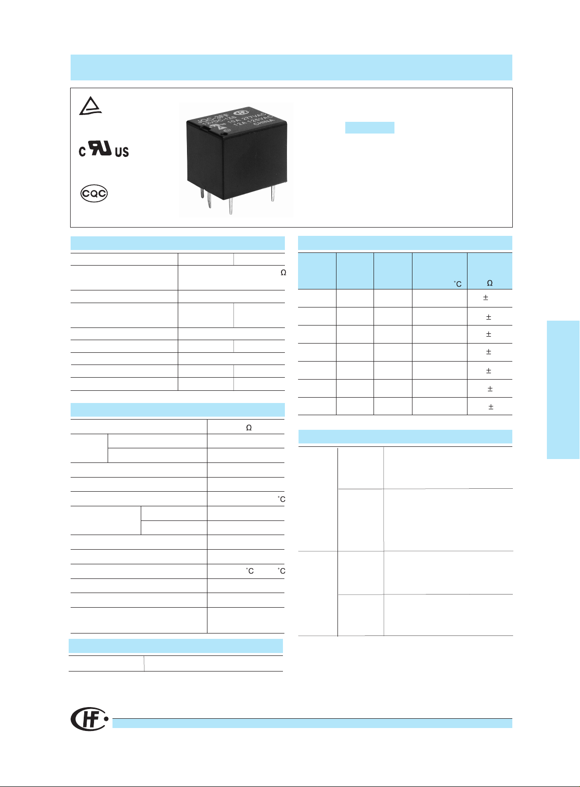
JQC-3FF
SUBMINIATURE HIGH POWER RELAY
File No.:R50034671
File No.:E133481
File No.:CQC02001001953
CONTACT DATA
Contact Arrangement
Initial Contact
Resistance Max.
Contact Material
Contact Rating (Res. Load) 10A 277VAC
Max. switching voltage
Max. switching current
Max. switching power
Mechanical life
Electrical life
1A
15A
1C
100m
(at 1A 6VDC)
Silver Alloy
7A 250VDC
10A 277VAC
277VAC/30VDC
10A
2770VA 210W
1 x 10
1 x 10
7
OPS
5
OPS
Features
*
*
*
*
COIL DATA
Nominal
Voltage
VDC
12
18
24
Pick-up
Voltage
VDC
5
6
9
3.80
4.50
6.80
9.00
13.5
18.0
Extremely low cost
SPST-NO & SPDT configuration
Subminiature, standard PCB layout
Sealed IP67 and Flux proof types available
Drop-out
Voltage
VDC
0.5
0.6
0.9
1.2
1.8
2.4
Max.
allowable
Voltage
VDC(at 25
6.5
7.8
11.7
15.6
23.4
31.2
Coil
Resistance
)
70 10%
100 10%
225 10%
400 10%
900 10%
1600 10%
General Purpose Power Relays
CHARACTERISTICS
Initial Insulation Resistance
Dielectric
Strength
Operate time (at nomi. Volt.)
Release time (at nomi. Volt.)
Temperature rise (at nomi. Volt.)
Shock Resistance
Vibration Resistance
Humidity
Ambient temperature
Termination
Unit weight
Construction
Between coil and contacts
Between open contacts
Functional
Destructive
COIL
Coil power
100M ,500VDC
1.5mm, 10 to 55Hz
*48VDC : 0.51W*
0.36W
1500VAC, 1min
750VAC, 1min
Max. 10ms
Max. 5ms
Max. 60
98 m/s2(10g)
980 m/s2(100g)
35% to 85%RH
-40
to +85
PCB
Approx. 10g
Sealed IP67
& Flux proof
48
36.0
4.8
62.4
SAFETY APPROVAL RATINGS
1 Form C
1/2 HP 125/250VAC
UL
1 Form A
1 Form C
TüV
1 Form A
12A 125VAC cos phi=1
5A 250VAC cos phi=1
12A 125VAC cos phi=1
5A 250VAC cos phi=1
4500 10%
10A 277 VAC
10A 120VAC
10A 277VAC
TV-5 120VAC
15A 125VAC
120VAC 125VAC
1/2hp,125VAC
8A 250VAC
10A 277VAC
JQC-3FF
HONGFA RELAY
ISO9001*ISO/TS16949 *ISO14001 CERTIFIED
VERSION: EN02-20040601
47
ORDERING INFORMATION
Type
Coil voltage 5, 6, 9, 12, 18, 24, 48VDC
Contact arrangement 1H:1 Form A (SPST-NO) 1Z:1 Form C (SPDT)
Structure S: Sealed IP67 Nil: Flux proof
Contact Material T: AgSnO
Insulation System F: Class F 155 Nil: Class B 130
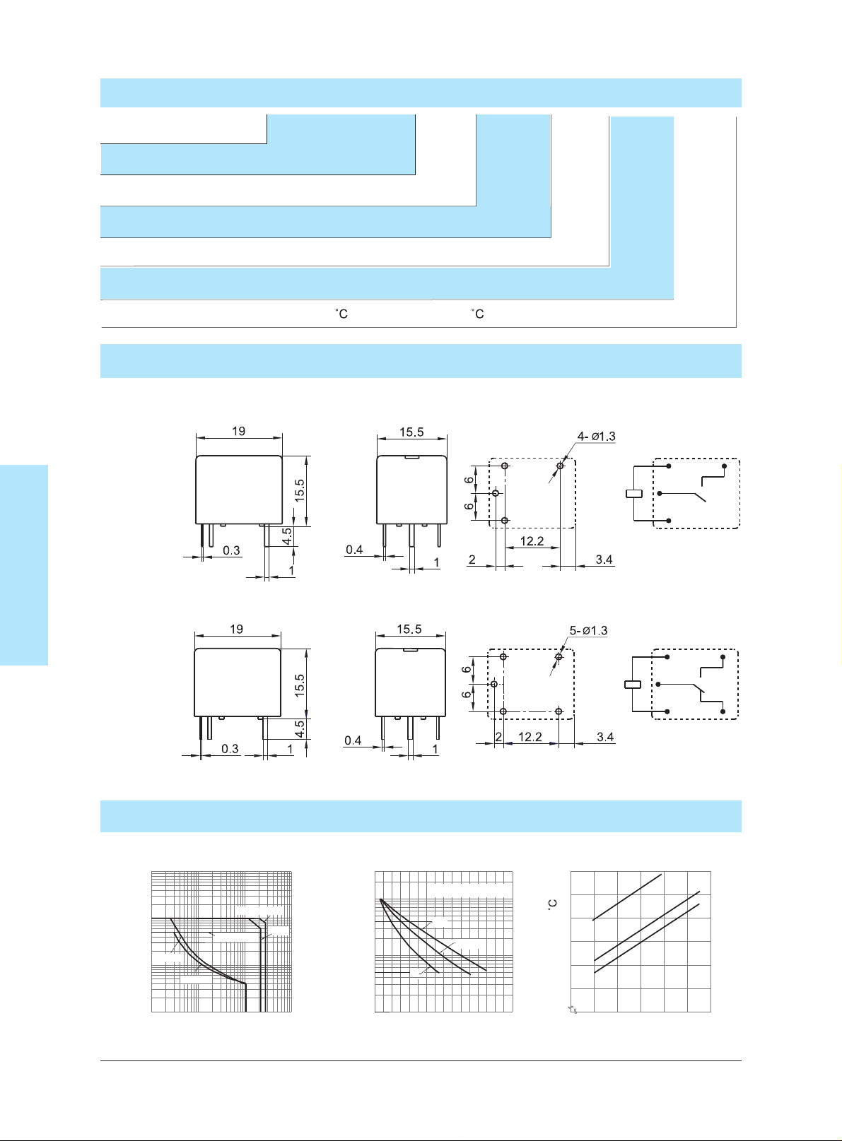
OUTLINE DIMENSIONS, WIRING DIAGRAM AND PC BOARD LAYOUT
General Purpose Power Relays
1A
JQC-3FF / 012 1H
Nil: AgCdo
2
Outline Dimensions Wiring DiagramPCB layout
S
T
F
JQC-3FF
1C
CHARACTERISTICS CURVE
MAXIMUM SWITCHING POWER
100
AC(1Z)
AC(1HT)
(1ZT)
100
1000
10
(1ZT,1HT)
1
Contact Current (A)
DC(1Z,1H)
10
Contact Voltage (V)
LIFE CURVE
100
50
10
5
Operations (X10000 OPS)
0 5
30VDC,250VAC
1HT
1Z
Contact Current (A)
1ZT,1H
10
(Resistive)
Bottom view
15
Bottom view
COIL TEMPERATURE RISE
60
50
40
10A
30
5A
20
0A
Temperature rise( )
10
800
90 100 110 120
Percentage Of Nominal Coil Voltage
130
48
 Loading...