

Page 1

User Manual
H792x 3G/4G Router
Page 2

Page 3

H792x 3G/4G Router Content
We Hongdian provide full support to customers, contact us freely if any questions.
F14-16,Headquarter Economic Center Building, Zhonghaixin Science&Tech Park, Bulan Road,
Longgang District, Shenzhen
Website
Technical Support
Fax number
Postalcode
Shenzhen Hongdian Technologies Corporation
Address
http://www.hongdian.com
+86-0755-88864288-4/8238
0755-83404677
518112
Copyright © Shenzhen Hongdian Technologies Corporation. 2014. All rights reserved.
All information in this user manual is protected by copyright law. Whereby, no organization or individual shall copy
or reproduce the whole or part of this user manual by any means without written authorization from Shenzhen
Hongdian Technologies Corporation.
Trademarks and Permissions
and DTU are the trademarks and logos of Shenzhen Hongdian Technologies Corporation. Other trademarks
and logos mentioned in this manual belong to other organizations related. Shenzhen Hongdian Technologies
Corporation does not own the rights of other trademarks and logos.
Caution
Due to product updates or functional upgrading, we may renew the content of this file, and this file only for
reference. All statement, information, suggestion.etc in this file do not compose any form of guarantee and we
Hongdian reserves the right of final explanation.
i
Page 4

Purpose
H792x 3G/4G router is designed and manufactured by Hongdian, it based on 3G/4G cellular
network technology, industrial class quality. With its embedded cellular module, it has been
widely used in finance, transportation, telecom, electricity, security system and other
industries. This document introduced how to use H792x and its function features.
Related Versions
H792X 3G/4G Router
About This Document
The following table lists the product versions related to this document.
Organization
Model Version
H792x V14
Chapter Description
1
2 SW & HW structure of H792x 3G/4G router.
3 How to installation of H792x 3G/4G router.
4 Prepare to config H792x 3G/4G router.
5 How to config H792x 3G/4G router.
6 Typical application of H792x 3G/4G router.
Features of H792x 3G/4G router and target market.
7 Frequently asked questions.
ii
(2014-05-28)
Page 5

H792x 3G/4G Router Content
Conventions
Symbol Conventions
The symbols that may be found in this document are defined as follows.
Symbol Description
Indicates a potentially hazardous situation, which if not avoided,
could result in equipment damage, data loss, performance
degradation, or unexpected results.
Indicates a tip that may help you address a problem or save your
time.
Provides additional information to emphasize or supplement
important points of the main text.
Command Conventions
Convention Description
Boldface The keywords of a command line are in boldface.
Italic Command arguments are in italics.
[ ] Items (keywords or arguments) in brackets [ ] are optional.
{ x | y | ... } Optional items are grouped in braces and separated by vertical ars.
One item is selected.
[ x | y | ... ] Optional items are grouped in brackets and separated by vertical
bars. One item is selected or no item is selected.
{ x | y | ... } * Optional items are grouped in braces and separated by vertical ars.
A minimum of one item or a maximum of all items can be selected.
[ x | y | ... ] * Optional items are grouped in brackets and separated by vertical
ars. Several items or no item can be selected.
&<1-n> The parameter before the & sign can be repeated 1 to n times.
# A line starting with the # sign is comments.
iii
Page 6

GUI Conventions
Convention Description
Boldface Buttons, menus, parameters, tabs, window, and dialog titles are
> Multi-level menus are in boldface and separated by the ">" signs.
Keyboard Operations
Format Description
Key Press the key. For example, press Enter and press Tab.
Key 1+Key 2 Press the keys concurrently. For example, pressing Ctrl+Alt+A means
H792X 3G/4G Router
in boldface. For example, click OK.
For example, choose File > Create > Folder.
the three keys should be pressed concurrently.
Key 1, Key 2 Press the keys in turn. For example, pressing Alt, A means the two
Mouse Operation
Action Description
Click Select and release the primary mouse button without moving the
Double-click Press the primary mouse button twice continuously and quickly
Drag Press and hold the primary mouse button and move the pointer to a
keys should be pressed in turn.
pointer.
without moving the pointer.
certain position.
iv
(2014-05-28)
Page 7

H792x 3G/4G Router Content
Content
1 Product Introduce
1.1 Overview............................................................................................................................................................ 1
1.2 Product positioning............................................................................................................................................ 1
1.3 Function & Features...........................................................................................................................................2
1.4 Specification...................................................................................................................................................... 3
2 Product structure
2.1 Hardware............................................................................................................................................................ 5
2.1.1 Appearance & Size................................................................................................................................... 5
2.1.2 Accessories............................................................................................................................................... 7
2.2 Structure............................................................................................................................................................. 7
..........................................................................................................................
............................................................................................................................
3 Installation of H792x 3G/4G Router.......................................................................................... 8
3.1 Unpacking.......................................................................................................................................................... 8
3.2 How to install.....................................................................................................................................................8
3.2.1 SIM/UIM card install................................................................................................................................8
3.1.2 Ethernet cable connection.........................................................................................................................9
3.1.3 Serial port connection............................................................................................................................... 9
3.2 Power supply....................................................................................................................................................10
3.3 Review............................................................................................................................................................. 10
1
4
4 Before config
LED Status
4.1
Local config
4.1
4.2 Basic config.........................................................................................................................................................8
4.2.1 Login WEB GUI.......................................................................................................................................... 8
5
Router config
5.1 Overview............................................................................................................................................................ 1
5.2 Network config...................................................................................................................................................1
5.2.1 LAN............................................................................................................................................................2
5.2.2 Modem..................................................................................................................................................... 3
5.2.3 Parameter select.......................................................................................................................................9
5.2.4
5.2.5
5.3 Application program configuration..................................................................................................................15
.....................................................................................................................................
...........................................................................................................................................................1
.........................................................................................................................................................2
.....................................................................................................................................1
Network type
DHCP Service
.......................................................................................................................................... 11
...........................................................................................................................................12
1
v
Page 8

H792X 3G/4G Router
5.3.1 ICMP check............................................................................................................................................ 15
5.3.2 DDNS configuration...............................................................................................................................17
5.3.3 SNMP configuration............................................................................................................................... 19
5.3.4 M2M configuration.................................................................................................................................21
5.3.5 Timing configuration.............................................................................................................................. 23
5.3.6 Wake up configuration............................................................................................................................25
5.3.7 DTU configuration................................................................................................................................. 28
5.4 Security............................................................................................................................................................ 31
5.4.2 Overview................................................................................................................................................ 31
5.4.3 Configuration.......................................................................................................................................... 31
5.5 Forward configuration..................................................................................................................................... 38
5.5.2 Overview................................................................................................................................................ 38
5.5.3 NAT........................................................................................................................................................ 38
5.5.4 Static Routing......................................................................................................................................... 42
5.5.5 QoS (Optional)....................................................................................................................................... 45
5.5.6 Dynamic Routing (Optional).................................................................................................................. 47
5.6 VPN configuration (H7921 only).................................................................................................................... 52
5.6.2 Overview................................................................................................................................................ 52
5.6.3 VPDN configuration...............................................................................................................................53
5.6.4 Tunnel configuration...............................................................................................................................55
5.6.5 IPSec configuration................................................................................................................................ 56
5.7 System configuration....................................................................................................................................... 62
5.7.2 Overview................................................................................................................................................ 62
5.7.3 Local Log................................................................................................................................................62
5.7.4 Remote Log............................................................................................................................................ 63
5.7.5 Clock.......................................................................................................................................................64
5.7.6 Account................................................................................................................................................... 66
5.7.7 Network Test...........................................................................................................................................68
5.7.8 Files........................................................................................................................................................ 69
5.8 Status................................................................................................................................................................75
5.8.2 Overview................................................................................................................................................ 75
5.8.3 Base Information.................................................................................................................................... 75
5.8.4 LAN........................................................................................................................................................ 76
5.8.5 Modem....................................................................................................................................................77
5.8.6 Routing Table..........................................................................................................................................78
5.9 RESET button function....................................................................................................................................80
6 Typical application
Overview
6.3
Awake function
6.4
VPN
6.5
6.6
..................................................................................................................................................
7 FAQ
vi
...................................................................................................................................................................82
Timing Task
..........................................................................................................................
.......................................................................................................................................................... 81
................................................................................................................................................ 81
.......................................................................................................................................................86
81
87
(2014-05-28)
Page 9

H792x 3G/4G Router Content
Hardware Failure
7.3
All LED dark
7.3.2
SIM Slot
7.3.3
Ethernet Connection
7.3.4
Antenna Connection
7.3.5
Dial Online Problem
7.4
Dial discontinue
7.4.2
No Signal
7.4.3
.............................................................................................................................................. 88
............................................................................................................................................. 88
................................................................................................................................................... 88
...............................................................................................................................88
............................................................................................................................... 89
......................................................................................................................................... 89
...................................................................................................................................... 89
................................................................................................................................................. 89
7.4.4 Cannot find SIM/UIM card......................................................................................................................90
7.4.5 Poor Signal.............................................................................................................................................. 90
7.4.6 Compress Protocol not match................................................................................................................ 90
7.5 VPN Problem.................................................................................................................................................... 91
7.5.2 VPDN cannot connect.............................................................................................................................91
7.5.3 VPN cannot communicate...................................................................................................................... 91
7.5.4 Router can communicate but subnet cannot......................................................................................... 91
WEB config problem
7.6
Updating firmware failure
7.6.2
Updating patch failure
7.6.3
CFE Updating failure
7.6.4
Update failure in WEB GUI
7.6.5
Forget Router Password
7.6.6
........................................................................................................................................ 92
.......................................................................................................................92
............................................................................................................................ 92
............................................................................................................................... 92
......................................................................................................................93
..........................................................................................................................93
vii
Page 10

H792X 3G/4G Router
Table Content
Table 2-1 H792x 3G/4G Router size....................................................................................................................... 5
Table 2-2 H792x 3G/4G Router accessories............................................................................................................7
Table 4-3 LED instruction....................................................................................................................................... 1
Table 5-4 LAN Parameter instruction......................................................................................................................2
Table 5-5 “Modem” Parameter instruction.............................................................................................................. 4
Table 5-6 Parameter instruction............................................................................................................................. 10
Table 5-7 Network type Parameter instruction...................................................................................................... 12
Table 5-8 DHCP Parameter....................................................................................................................................13
Table 5-9 ICMP check rules Parameter instruction............................................................................................... 16
Table 5-10 DDNS Parameter instruction............................................................................................................... 18
Table 5-11 SNMP Parameter instruction............................................................................................................... 20
Table 5-12 M2M Parameter instruction.................................................................................................................22
Table 5-13 Timing task parameter instruction....................................................................................................... 24
Table 5-14 Wake up Parameter instruction............................................................................................................ 26
Table 5-15 DTU Parameter instruction..................................................................................................................29
Table 5-16 IP filter parameter instruction.............................................................................................................. 34
Table 5-17 Domain Filter parameter instruction....................................................................................................36
Table 5-18 MAC Filter explanation.......................................................................................................................37
Table 5-19 MAC Filter Parameter instruction....................................................................................................... 37
Table 5-20 DNAT Parameter instruction............................................................................................................... 39
Table 5-21 SNAT rule instruction.......................................................................................................................... 41
Table 5-22 MASQ rule Parameter instruction....................................................................................................... 42
Table 5-23 Static Routing Parameter Instruction...................................................................................................44
Table 5-24 QoS parameter instruction................................................................................................................... 46
Table 5-25 RIP Parameter Instruction....................................................................................................................48
Table 5-26 RIP parameter instruction.................................................................................................................... 49
Table 5-27 OSPF parameter instruction.................................................................................................................50
Table 5-28 OSPF route parameter instruction....................................................................................................... 51
Table 5-29 VPDN rule parameter instruction........................................................................................................ 54
Table 5-30 Tunnel rule parameter instruction........................................................................................................56
viii
(2014-05-28)
Page 11

H792x 3G/4G Router Content
Table 5-31 IPSec Phase 1 Parameter instruction................................................................................................... 58
Table 5-32 IPSec Parameter instruction.................................................................................................................60
Table 5-33 IPSec Parameter instruction.................................................................................................................61
Table 5-34 Remote log parameter instruction........................................................................................................64
Table 5-35 Clock Parameter instruction................................................................................................................ 65
Table 5-36 Account parameter instruction............................................................................................................. 67
Table 5-37 Network Test Parameter instruction.................................................................................................... 68
Table 5-38 Base information Parameter instruction.............................................................................................. 76
Table 5-39 LAN Parameter instruction..................................................................................................................77
Table 5-40 Modem Parameter instruction..............................................................................................................78
Table 5-41 Routing table Parameter instruction.................................................................................................... 80
ix
Page 12

Page 13

H792x 3G/4G Router
Figure Content
Figure 1-1 Network structure...................................................................................................................................2
Figure 2-2 H792x 3G/4G Router Appearance......................................................................................................... 5
Figure 2-3 H792x 3G/4G Router Figure..................................................................................................................6
Figure 2-4 Front pannel........................................................................................................................................... 7
Figure 2-5 Back pannel............................................................................................................................................7
Figure 3-6 Pop out SIM slot.................................................................................................................................... 9
Figure 3-7 SIM/UIM card install............................................................................................................................. 9
Figure 4-8 Local Area Connection............................................................................................................................2
Figure 4-9 Connection properties........................................................................................................................... 3
Figure 4-10
Figure 4-11 Advanced TCP/IP Settings.....................................................................................................................5
Figure 4-12 TCP/IP address...................................................................................................................................... 6
Figure 4-13
Figure 4-14 User identity page................................................................................................................................ 8
Figure 5-15 LAN window........................................................................................................................................2
Figure 5-16 Modem window................................................................................................................................... 3
Figure 5-17 Modem page........................................................................................................................................ 4
Figure 5-18
Figure 5-19 Single module dual SIM........................................................................................................................7
Figure 5-20 Advanced setting.................................................................................................................................. 8
Figure 5-21
Figure 5-22 add rule.............................................................................................................................................. 10
Figure 5-23 Network type window........................................................................................................................ 11
Figure 5-24 DHCP................................................................................................................................................. 13
Figure 5-25 ICMP Check tab................................................................................................................................. 15
Internet protocol (TCP/IP)
Connectivity check
Single module single SIM/dual module dual SIM
parameter select
.................................................................................................................................. 9
.................................................................................................................... 3
............................................................................................................................... 7
................................................................................ 7
Figure 5-26 ICMP adding page..............................................................................................................................16
Figure 5-27 DDNS configuration.......................................................................................................................... 18
Figure 5-29 SNMP configuration.......................................................................................................................... 20
Figure 5-30 M2M configuration............................................................................................................................ 22
Figure 5-31 Timing configuration..........................................................................................................................23
(2014-05-28)
xi
Page 14

H792X 3G/4G Router
Figure 5-32 To add timing task.............................................................................................................................. 24
Figure 5-33 Wake up configuration....................................................................................................................... 26
Figure 5-34 DTU configuration............................................................................................................................. 28
Figure 5-35 IP Filter tab.........................................................................................................................................32
Figure 5-36 IP filter “Input” type...........................................................................................................................33
Figure 5-37 IP Filter “Forward” type.....................................................................................................................33
Figure 5-38 Domain filter tab................................................................................................................................ 35
Figure 5-39 Domain filter tab................................................................................................................................ 36
Figure 5-40 MAC Filter tab................................................................................................................................... 36
Figure 5-41 MAC Filter configuration.................................................................................................................. 37
Figure 5-42 NAT tab.............................................................................................................................................. 38
Figure 5-43 DNAT rule configuration................................................................................................................... 39
Figure 5-44 SNAT rule configuration.................................................................................................................... 40
Figure 5-45 MASQ configuration..........................................................................................................................42
Figure 5-46 Static Routing Interface..................................................................................................................... 43
Figure 5-47 Static Routing Interface..................................................................................................................... 43
Figure 5-48 Policy Routing Interface.................................................................................................................... 44
Figure 5-49 QoS interface......................................................................................................................................46
Figure 5-50 RIP interface.......................................................................................................................................48
Figure 5-51 RIP route configuration interface....................................................................................................... 49
Figure 5-52 OSPF Interface................................................................................................................................... 50
Figure 5-53 OSPF route configuration interface................................................................................................... 51
Figure 5-54 VPDN configuration.......................................................................................................................... 53
Figure 5-55 VPDN rule configuration................................................................................................................... 53
Figure 5-56 L2TP tunnel status..............................................................................................................................54
Figure 5-57 Tunnel configuration.......................................................................................................................... 55
Figure 5-58 IPSec tab............................................................................................................................................ 57
Figure 5-59 IPSec phase 1 configuration...............................................................................................................58
Figure 5-60 IPSec phase 2 configuration...............................................................................................................60
Figure 5-61 IPSec configuration tab...................................................................................................................... 61
Figure 5-62 Local Log tab..................................................................................................................................... 63
Figure 5-63 Remote Log tab.................................................................................................................................. 64
Figure 5-64 “NTP” Time Synch............................................................................................................................ 65
Figure 5-65 Manual Time Synch. Type................................................................................................................. 65
Figure 5-66 Account tab........................................................................................................................................ 67
Figure 5-67 Network Test Tab............................................................................................................................... 68
Figure 5-68 Files tab.............................................................................................................................................. 69
Figure 5-69 Add an IP address............................................................................................................................... 70
xii
(2014-05-28)
Page 15

H792x 3G/4G Router
Figure 5-70 CFE mode upgrading......................................................................................................................... 71
Figure 5-71 CFE upgrading page...........................................................................................................................71
Figure 5-72 Backup setting page........................................................................................................................... 72
Figure 5-73 Factory setting page........................................................................................................................... 73
Figure 5-74 Patch operation...................................................................................................................................74
Figure 5-75 reboot................................................................................................................................................. 75
Figure 5-76 Base Information tab.......................................................................................................................... 76
Figure 5-77 “LAN” info........................................................................................................................................ 77
Figure 5-78 Modem Status page............................................................................................................................ 78
Figure 5-79 Routing table page............................................................................................................................. 79
Figure 6-80
Figure 6-81 Build IPSec.......................................................................................................................................... 83
Figure 6-82
Figure 6-83 IPSec Phase 2......................................................................................................................................84
Figure 6-84
Figure 6-85
Figure 6-86 Timing.................................................................................................................................................86
Figure 6-87
Figure 6-88
Figure 6-89
Wake up/trigger setting example
IPSec Phase 1
IPSec
................................................................................................................................................... 85
IPSec status
router online
router off line
router reboot
......................................................................................................................................84
.........................................................................................................................................85
.......................................................................................................................................86
..................................................................................................................................... 87
......................................................................................................................................87
....................................................................................................... 82
(2014-05-28)
xiii
Page 16

Page 17

H792x 3G/4G Router 4 Before config
1
Product Introduce
1.1 Overview
1.2 Product positioning
About this chapter
Chapter Content
1.1 Overview
1.2 Product Positioning Product Positioning of H792x 3G/4G Router
1.3 Function & features
1.4 Specification
H792x 3G/4G Router based on 3G/CELLULAR technology, except tradition router function like
VPN, firewall, NAT, SNMP, DHCP. H792x support 3G/CELLULAR as WAN interface, provide up
to 100Mbps WAN bandwidth and up to 150Mbps Wi-Fi bandwidth. Also, definable route
table makes customers could assign bandwidth by business type, full use the bandwidth and
lower the net delay.
H792x 3G/4G Router support Hongdian M2M management platform. By the management
platform, you can check running info of H792x 3G/4G Router and remote config or remote
updates.
Simple introduction of H792x 3G/4G Router.
Unique function & features
Detail specification of this router
H792x 3G/4G Router widely used in Telecom, economic, advertisement, traffic, environment
protection business area.
For example, in economic area, H792x 3G/4G Router connect server by IPSec & GRE to
ensure data security, tiny design makes it could installed into ATM machine. All these
technology ensured safe and reliable data transmission, and minimize the probability of
network disconnection, and maximize the usability of economic business like ATM, POS .etc.
111
(2014-05-28) 4 -
1
Page 18

7 FAQ H792x 3G/4G Router
Figure 1-1 Networkstructure
1.3 Function & Features
Cellular module optional, HSPA/EVDO/LTE optional
VPN support, GRE over IPSec, IPsec over PPTP/L2TP.
LCP/ICMP/flow/heartbeat check, ensure network usability
SNMP network management, NTP support
Local & remote firmware update
Local & remote log check
Supports DNS proxy and Dynamic DNS (DDNS)
Supports timing operation
Supports LED status indication
LTE FDD: B1,B2,B4,B5,B7,B8,B12
LTE FDD: B1,B3,B7,B8,B20
LTE FDD: B1,B3,B7,B8,B20
LTE FDD: B2,B4,B5,B13,B17,B25
LTE TDD: B38,B39,B40
Function
Available cellular network
LTE TDD: B38
LTE TDD: B40
2
7 -
(2014-05-28)
Page 19

H792x 3G/4G Router 4 Before config
HSPA+/HSUPA/HSDPA/WCDMA/UMTS 2100/1900/900/850/800MHz
EDGE/GPRS/GSM 1900/1800/900/850MHz
CDMA 2000/EVDO Rev.A 800/1900MHz
1.4 Specification
1×10/100Mb LAN interface
1× RS-232 console port (full DTU function optional)
1× SMA-K antenna interface
1× SMA-K antenna interface (Wi-Fi, optional)
1× Standard SIM/R-UIM interface
1× Standard DC power interface
Voltage: +5V~+36VDC
Idle: 40mA@12V DC
Communication: 240mA@12V DC
Dimension: 98mm x 100mm x 23mm (not including antenna)
Weight: 320g
Operation temperature: -30~+70℃
Store temperature: -40~+85℃
Related humidity: <95% (non-condensing)
Guarantee: one year
LTE FDD: B7
Interface
Power supply
Others
333
(2014-05-28) 4 -
3
Page 20

7 FAQ H792x 3G/4G Router
2
Product structure
About this chapter
Chapter Content
2.1 Hardware H792x 3G/4G Router hardware.
2.2 Structure Structure of H792x 3G/4G Router.
7 -
4
(2014-05-28)
Page 21

H792x 3G/4G Router 4 Before config
2.1 Hardware
2.1.1 Appearance & Size
Figure 2-2 H792x 3G/4G Router Appearance
Table 2-1 H792x 3G/4G Router size
1×10/100Mb LAN interface
1× RS-232 console port (full DTU function optional)
1× SMA-K antenna interface
1× SMA-K antenna interface (Wi-Fi, optional)
1× Standard SIM/R-UIM interface
1× Standard DC power interface
Appearance
Size
Model Dimension (mm) Interface
H792x 3G/4G
Router
H792x 3G/4G Router appearance as Figure 2-3, shows
555
(2014-05-28) 4 -
98×100×23
5
Page 22

7 FAQ H792x 3G/4G Router
Figure 2-3 H792x 3G/4G Router Figure
7 -
6
(2014-05-28)
Page 23

H792x 3G/4G Router 4 Before config
2.1.2 Accessories
Table 2-2
H792x 3G/4G Router accessories
2.2 Structure
Figure 2-4 Front pannel
Figure 2-5 Back pannel
Accessories name Number Note
H792x 3G/4G Router 1 pcs
CD-ROM 1 pcs Optional
3G/CELLULAR antenna 1 pcs
Wi-Fi antenna 1 pcs Optional
GPS antenna 1 pcs Optional
RJ45 cable 1 pcs
Mounting 1 pair Optional
Certificate and warranty
card
+12V power adapter 1 pcs American Style as standard
1 pcs
SIM Holder
ANT RESET POWER LAN CONSOLE
777
(2014-05-28) 4 -
7
Page 24

7 FAQ H792x 3G/4G Router
3
Installation of H792x 3G/4G Router
3.1 Unpacking
3.2 How to install
3.2.1 SIM/UIM card install
Step 1 Use a small stick push the yellow button on router, the SIM slot will pop out as Figure 3-6
About this chapter
Chapter Content
3.1 Unpacking Unpack H792x 3G/4G Router box and the packing list.
3.2 How to install How to install H792x 3G/4G Router with SIM/UIM card and
Ethernet cable .etc.
3.3 Power supply Power supply needs of H792x 3G/4G Router.
3.4
Review Review
After received the box of H792x, please unpack it and check if all accessories complete.
Please check Table 2-2 as reference.
H792x 3G/4G Router support dual SIM/UIM carad, so you may need insert dual SIM before
config it.
Before install SIM/UIM card, disconnect any power resource of the router.
shows.
8
7 -
(2014-05-28)
Page 25

H792x 3G/4G Router 4 Before config
Figure 3-6 Pop out SIM slot
Step 2 Put SIM card in slot at proper direction as Figure 3-7 shows
Figure 3-7 SIM/UIM card install.
3.1.2 Ethernet cable connection
3.1.3 Serial port connection.
---END
Use Ethernet port directly connect H792x 3G/4G Router and computer, or transferred by a
switch.
When you connect H792x 3G/4G Router to serial port on lattop or ther deivec. To do this you
need a serial port or RJ45 cable, this cable is optional. One end connect to computer serial
port, other end connect the console port on H792x
999
(2014-05-28) 4 -
9
Page 26

7 FAQ H792x 3G/4G Router
This port for debug only, not for other application.
Do not insert any other RJ45 cable into console port, otherwise router may work
3.2 Power supply
3.3 Review
Step 1 Check antenna connection.
Step 2 Check SIM/UIM card installation; confirm SIM/UIM card is available.
Step 3 Power on H792x 3G/4G Router, the LEFT SIM slot is SIM 1, take it as a example:
After connect power 14s, router RUN solid light, means router system works ok.
After connect power 25s, NET solid light, means router found the module.
After connect power 25s, NET blinking quickly means router start to dial.
After connect power 30s, RF shows the signal level.
After connect power 45s, NET solid light means 3G/CELLULAR connected, if blinking slowly,
abnormal.
In order to get high reliability, H792x 3G/4G Router adapt wide voltage input: +5V~+36VDC,
support hot plug and complex application environment.
After connect SIM/UIM card, Ethernet cable, necessary antenna, then connect power cable.
Notice
Please connect antenna before connect power cable, otherwise because of Impedance
mismatching, signal maybe poor.
means 2G/2.5G connected.
10
7 -
(2014-05-28)
Page 27

H792x 3G/4G Router 4 Before config
4
Before config
4.1 LED Status
Table 4-3 LED instruction
Solid light: system normal
Dark: system abnormal or during booting
Solid light: connect ok
Blinking: data sending/receiving.
Dark: no connection.
Solid light: good signal, 21~31
Blinking quickly (0.5s): normal signal, 11~20
Blinking slowly(2s): bad signal, 1~10
Dark: no signal
Solid light: connect 3G/CELLULAR ok
Blinking slowly(0.5s): connect 2.5G network ok
Blinking quickly(2s): dialing
Dark:No module or no auto-dial
About this chapter
Chapter Content
4.1 LED Status
4.1 Local config
4.3 Basic config
There are LED on front panel of H792x 3G/4G router, they show how H792x 3G/4G router
works.
LED name Status
SYS
LAN
RF
The meaning of LED status.
How to local config H792x 3G/4G router.
Basic config & function.
NET
111
(2014-05-28) 4 -
1
Page 28

7 FAQ H792x 3G/4G Router
4.1 Local config
Already power on H792x 3G/4G router
Ethernet cable connect to H792x 3G/4G router
Step 1 Click “start > control panel”, find “Network Connections” icon and double click it to enter,
Figure 4-8 Local Area Connection
Step 2 Obtain a IP address automatically, or follow below instruction.
Step 3 Change or add a IP 192.168.8.* on your computer.
Precondition
You could specify a static IP or DHCP get IP for your computer.
Static IP
select “Local Area Connection” corresponding to the network card on this page. Refer
to the figure below.
H792x 3G/4G Router default enabled DHCP server. If it has been disabled, DHCP cannot be use.
2
7 -
(2014-05-28)
Page 29

H792x 3G/4G Router 4 Before config
Figure 4-9 Connection properties
Figure 4-10 Internet protocol (TCP/IP)
333
(2014-05-28) 4 -
3
Page 30

7 FAQ H792x 3G/4G Router
General configuration
You could change your IP address or add a IP address in Advanced setting.
This method will temporarily interrupts the communication between the computer
under configuration and LAN, and the specific parameter configuration is shown as
below:
IP address: 192.168.8.* (*indicates any integral between 2 to 254)
Subnet mask: 255.255.255.0
Default gateway: 192.168.8.1
Remember:
H792x 3G/4G Router LAN port factory default parameter:
IP address: 192.168.8.1
Subnet mask: 255.255.255.0
H792x 3G/4G Router factory default login parameter:
Management interface login IP address: 192.168.8.1
Login name: admin
7 -
4
(2014-05-28)
Page 31
H792x 3G/4G Router 4 Before config
Advanced configuration
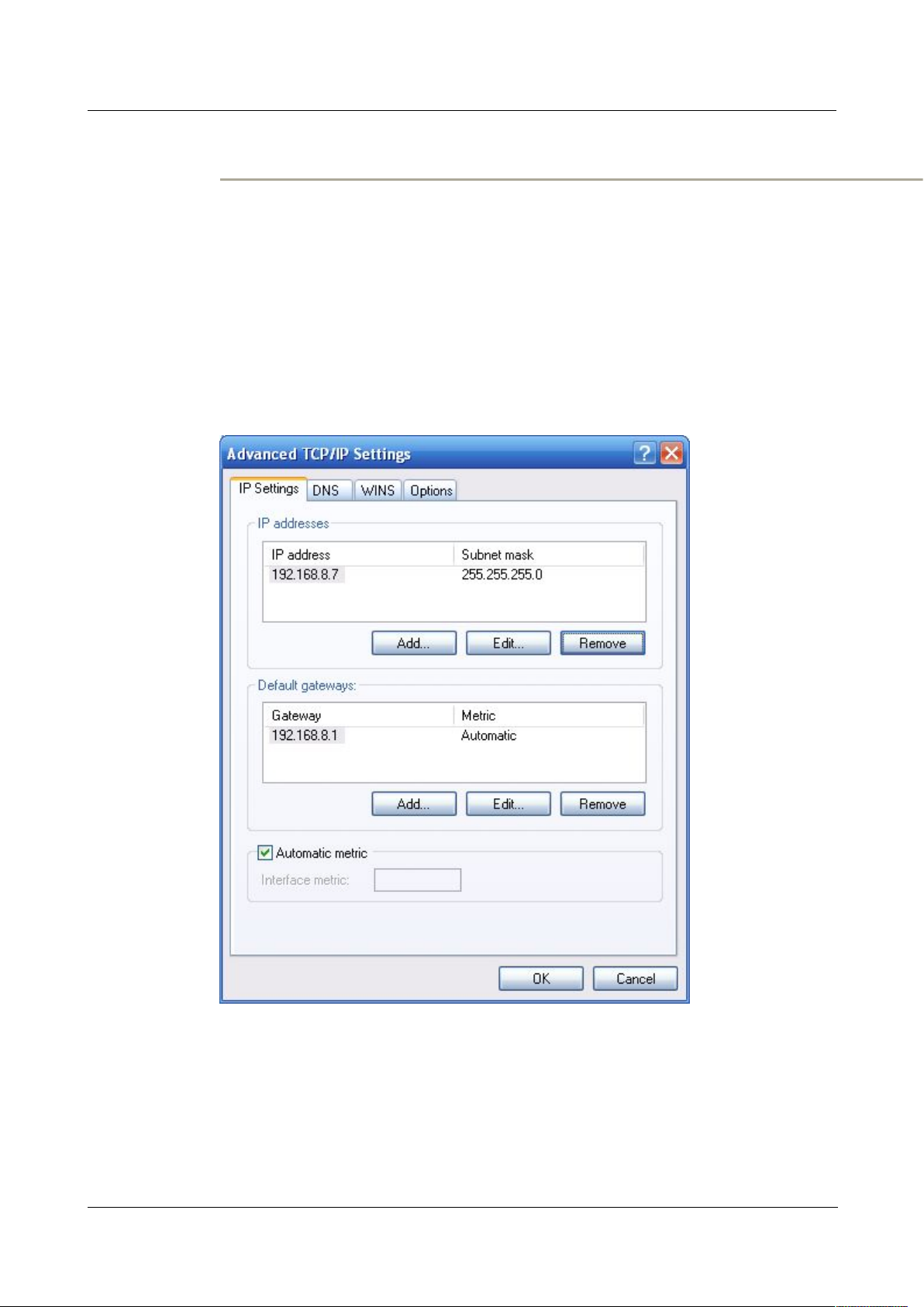
Figure 4-11 Advanced TCP/IP Settings
Login password: admin
If you don’t want to interrupt local PC LAN communication and configure H792x 3G/4G
Router when the former network configuration exists, it is required add route (IP).
The configuration operation is shown as below:
Click the “Advanced…”button to enter the interface as below:
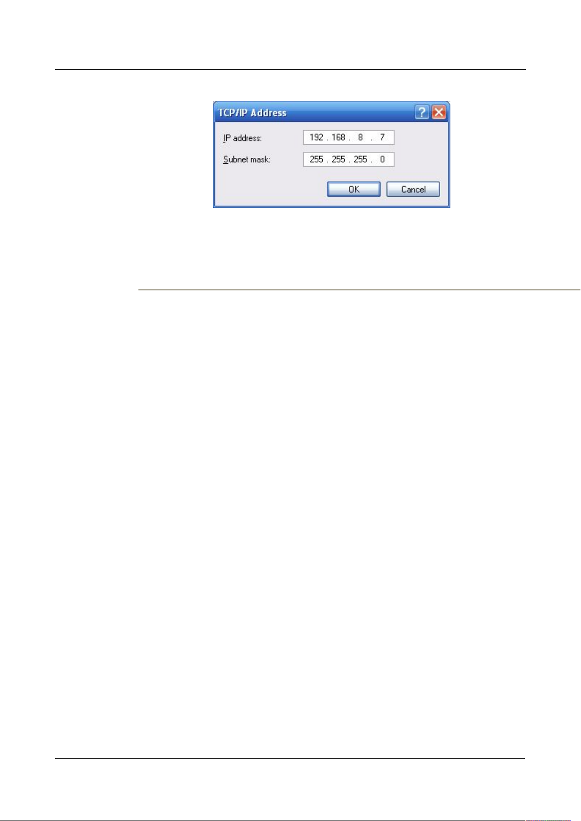
Click the “Add (A)”button under the “IP address (R)”, and fill in the IP address that you
want to add:
555
(2014-05-28) 4 -
5
Page 32
7 FAQ H792x 3G/4G Router
Figure 4-12 TCP/IP address
After the configuration is completed, click the “Add”. By now the computer has a route
to router H792x.
Note:
“Default gateway” depends on whether the configuration computer connects with
Internet through original local network configuration. If Internet is accessed through
original local network, the default gateway setting does not need to be modified; if
H792x 3G/4G Router is used, you need to modify the default gateway and configure it
as H792x 3G/4G Router’s default LAN IP address 192.168.8.1.
---END
7 -
6
(2014-05-28)
Page 33
H792x 3G/4G Router 4 Before config
Step 4 IP configuration check
Step 5 Connectivity check
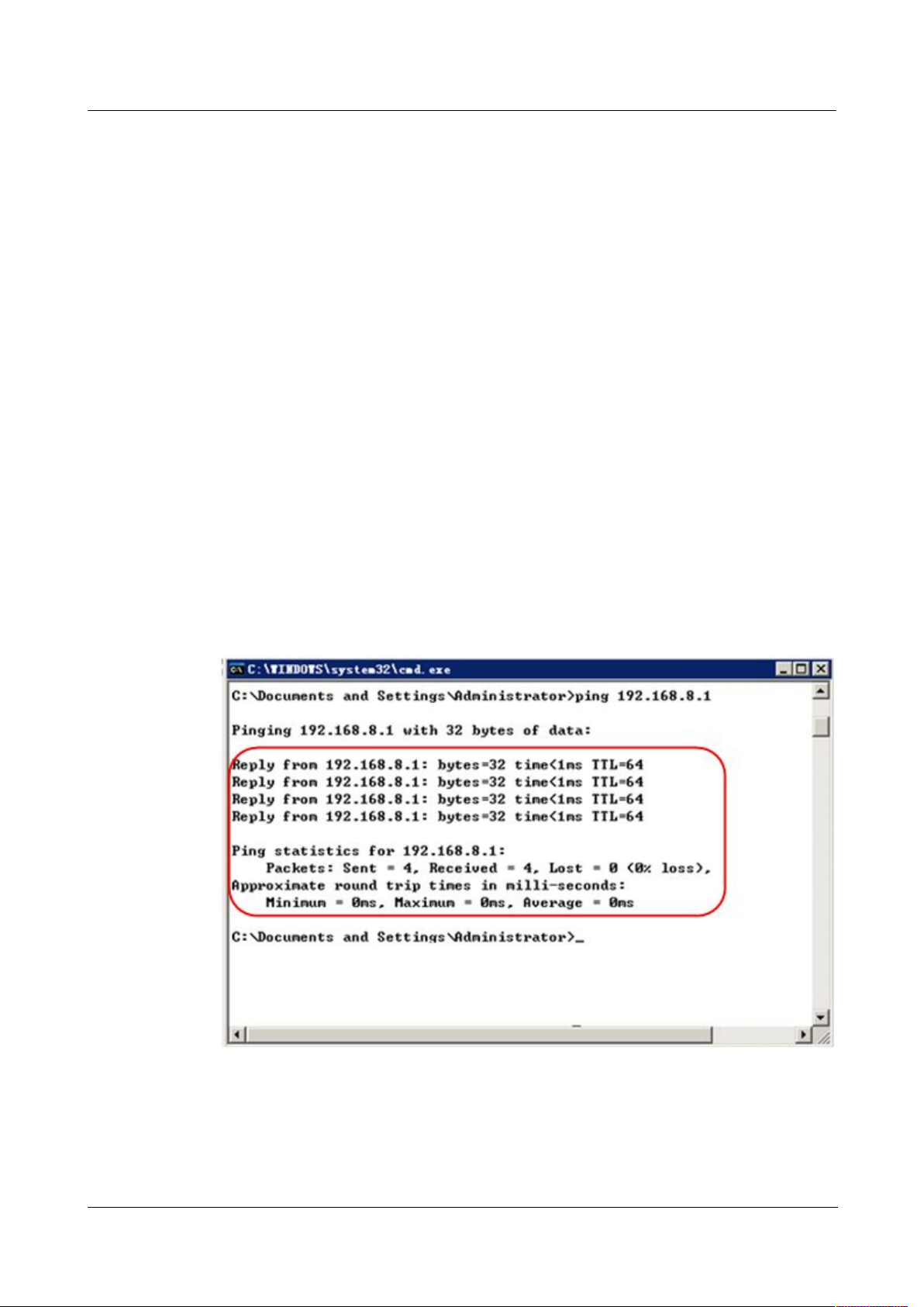
Figure 4-13 Connectivity check
Network Check
se the command of ipconfig to check whether the IP address is correctly set or added.
U
You can enter DOS mode and key-in command: ipconfig, for instance:
C:\>ipconfig
Windows IP Configuration
Ethernet adapter local connection:
Connection-specific DNS Suffix. :
Auto configuration IP Address . . .: 192.168.8.7
Subnet Mask . . . . . . . . . . .: 255.255.255.0
Default Gateway . . . . . . . . . : 192.168.8.1
After the configuration is completed, you can check the connectivity between it and
Galaxy H792x 3G/4G router by ping command. Key-in ping command in system
command line:
By now, it means that the configuration computer has been connected to the router.
You can carry out configuration operation on it.
---END
777
(2014-05-28) 4 -
7
Page 34
7 FAQ H792x 3G/4G Router
4.2 Basic config
4.2.1 Login WEB GUI
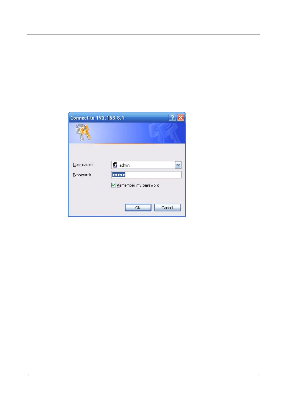
Step 1 Run a Internet Explorer and visit “http://192.168.8.1/”, to enter identity page.
Figure 4-14 User identity page
Step 2
User should use default user name and password when log in for the first time:
Through this chapter, you could achieve basic function: visit internet.
User name: admin
Password: admin
---END
8
7 -
(2014-05-28)
Page 35

H92x 3G/4G Router 7 FAQ
5
Router config
5.1 Overview
5.2 Network config
About this chapter
Chapter Content
5.1 Overview
5.2 Network config
5.3 Application
5.4 Security
5.5 Forward
5.6 VPN
5.7 System
5.8 Status
H792x 3G/4G router adopts WEB GUI to config, all parameter can be modified by this GUI,
and it is easy to understand.
Enter H792x 3G/4G Router WEB GUI to config
Network config & function
Advanced function of router like timing operation, link backup .etc.
Security setting of H792x
NAT & DMZ setting
PPTP, L2TP, IPSec & GRE setting
Updating & maintain
Router working status
Network connection config, including LAN, cellular network, parameter switch, DHCP setting
and so on.
Version (2014-05-28) 7 -
1
Page 36
7 FAQ H792x 3G/4G Router
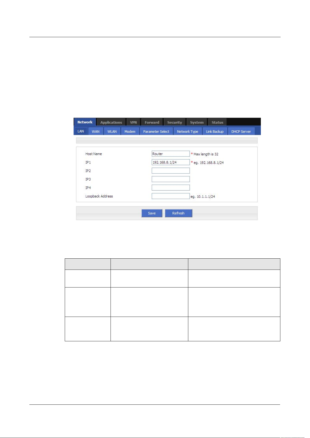
5.2.1 LAN
Step 1 Login H792x WEB GUI.
Step 2 Single click “Network > LAN”.
Figure 5-15
LAN window
Step 3 LAN parameter.
Table 5-4
LAN Parameter instruction
Step 4 Single click “save” icon, done.
LAN setting used to manage local area network PC which connects to H792x, make them
could visit internet and the network segment connectivity normal.
7 -
Parameter Details Operation
Host name router name Manual input, Maximum length
limited to 32 word type character
IP1~4
Loopback address Use for network test, e.g tunnel
2
Divide sub-network, those
sub-net could communicate
test, it won’t shutdown with the
lan interface closed
Manual input
Format:A.B.C.D/Mask
IP1 default:192.168.8.1/24
Ping IP address from peer of tunnel
(2014-05-28)
Page 37
H92x 3G/4G Router 7 FAQ
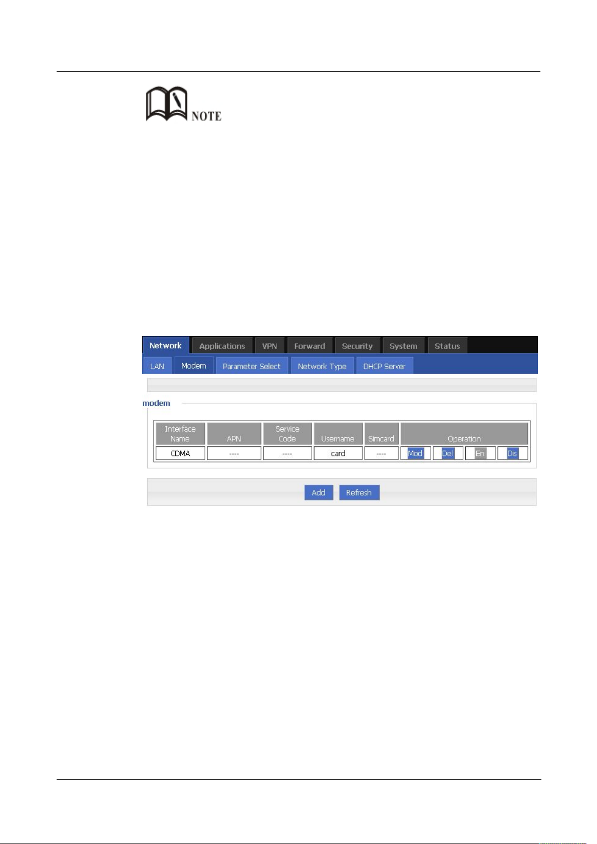
5.2.2 Modem
Step 1 Login H792x WEB GUI.
Step 2 Single click “network > Modem”.
Figure 5-16 Modem window
Step 3 Operation:
add
1. Single click “add”, window shows like below.
After change the LAN IP, if page has no response anymore, please make sure your PC address is in the
same network segment, or set a new IP to your PC to insure that.
---END
H792x 3G/4G Router core function, connect Internet by cellular modem, H792x 3G/4G
Router support single modem single SIM, single modem dual SIM, dual modem dual SIM,
those three working type provide internet connection to customers. Usually 3G network
bandwidth is 1~5Mbps, 3.5G up to 20Mbps and LTE up to 100Mbps.
Version (2014-05-28) 7 -
3
Page 38
7 FAQ H792x 3G/4G Router
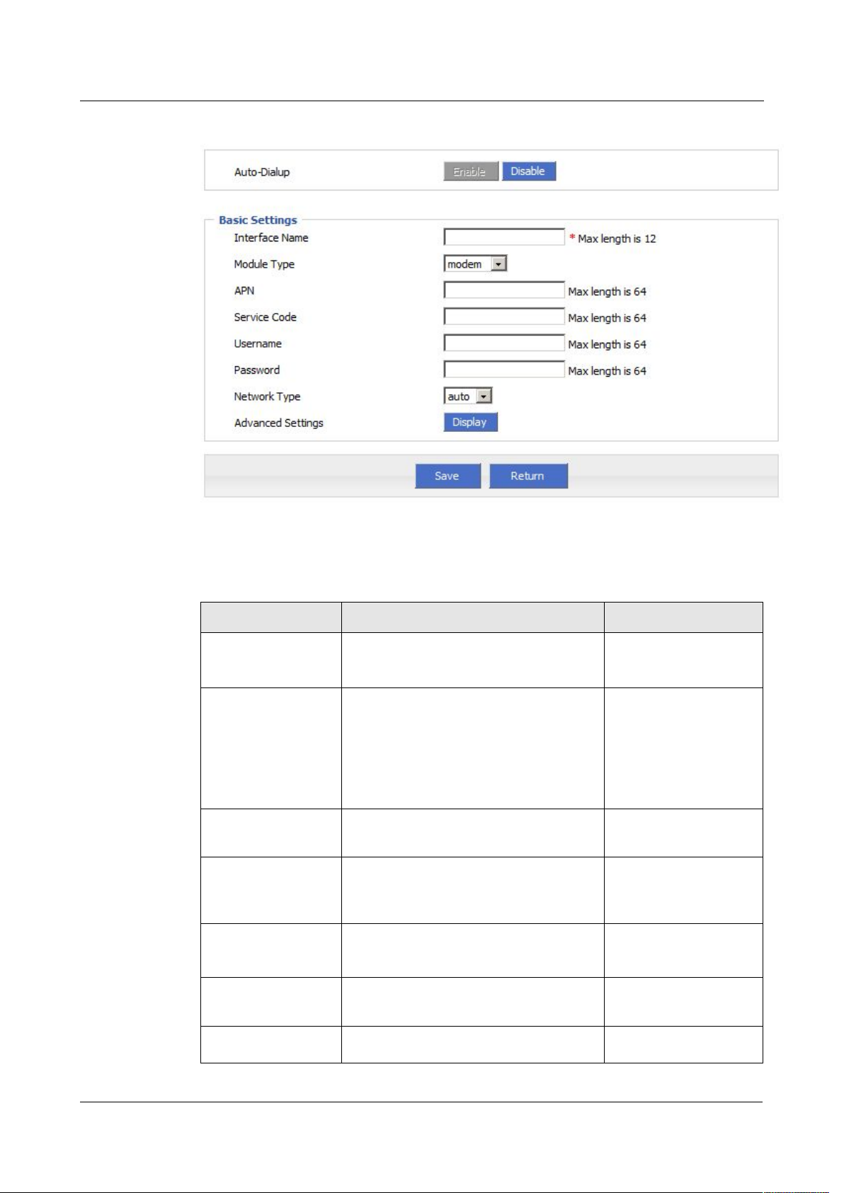
Figure 5-17 Modem page
2. Input suitable parameter.
Table 5-5
“Modem” Parameter instruction
Enable
Disable
modem
modem2
If your router has
SIM1
SIM2
Parameter Details Operation
Auto-dialup
Auto-dialup current modem, if all
modem auto-dialup disabled, router will
not auto-dialup
Module type
If your router has dual cellular module
Dropdown List
inside, you could choose which module
to use here.
only one module, no
such option.
Interface Name Interface name, to identify this interface WORD type, up to 12
characters
APN APN, provided by local ISP, usually
CDMA/EVDO network do not need this
WORD type, up to 64
bytes
parameter
Service code Usually *99***1#,
CDMA/EVDO: #777
CODE type, up to 64
bytes
Username/Password Provided by ISP WORD type/CODE
type, up to 64 bytes
7 -
SIM Only Single module dual SIM router has
4
(2014-05-28)
Page 39

H92x 3G/4G Router 7 FAQ
auto
wcdma
edge
auto
evdo
cdma
Disable
Negotiation
Disable
Negotiation
Disable
Negotiation
Disable
Negotiation
Disable
Negotiation
Disable
Negotiation
Disable
Negotiation
Disable
Negotiation
Disable
Negotiation
Disable
Negotiation
Parameter Details Operation
this option, used to select SIM card
Network type
Advance Setting
Network type force to 2.5G or 3G/4G
PPP process advanced parameter, do
not suggest modifying the setting. If
necessary, contact us for support
Authentication (need match server end, default auto-negotiation)
CHAP Challenge-Handshake Authentication
Protocol, a way to send real password
when build ppp link, improved security
Dropdown List
WCDMA:
EVDO:
LTE, HSPA+ module
force 3G means 3G/4G
auto, AUTO means
2.5G/3G/4G auto
Single click to show
advanced setting
CHAP is prior to PAP
PAP Password Authentication Protocol
MS-CHAP MS-CHAP
MicrosoftChallenge-Handshake
Authentication Protocol
Based on MPPE
MS2-CHAP MS-CHAP second version
EAP PPP Extensible Authentication Protocol
Compress (need match server end, default disable)
Compression
Control Protocol
Address/Control
Negotiate which compress control
protocol used on PPP link
Whether compress IP address
Compression
Protocol Field
Whether compress IP address
Compression
VJ TCP/IP Header
Compress
Whether allow TCP/IP to communicate
by compressing VJ
Connection-ID Whether allow TCP/IP to communicate
Version (2014-05-28) 7 -
5
Page 40

7 FAQ H792x 3G/4G Router
Disable
Negotiation
Disable
Negotiation
Value area
:
128
~
16364 byte
Value area : 128 ~
16364 byte
Set the remote IP address when PPP
dialing, need ISP support
nomppe
mppe required
mppe stateless
nodeflate
nobsdcomp
default-asyncmap
Parameter Details Operation
Compression by compressing ID in the first
More
Debug Enable PPP dialing log, default value is
enable, in order to check more info
about dialing, suggest no changing
Peer’s DNS Auto get peer DNS when PPP dialing.
DNS is necessary if want visit domain
name. In order to forbid LAN pc visit
domain name, you may disable it
LCP interval/Retry After PPP dialing succeed, LCP is needed
to keep PPP link alive. Also it could used
to quickly spot network interrupt and
reconnect
MTU
the number of bytes of the maximum
transfer unit
by PPP interface,
sometimes financial data has request on
this
MRU
the number of bytes of the maximum
receive unit by PPP interface,
sometimes financial data has request on
this
Local IP
Set the local IP address
when PPP
dialing, need ISP support
Remote IP
Professional
Value area:1~512
Unit: second
Default value: 30/5
A.B.C.D,
Example: 10.10.10.1
A.B.C.D,
Example: 10.10.10.254
Do not suggest modify,
please contact us for
help if necessary
6
7 -
(2014-05-28)
Page 41
H92x 3G/4G Router 7 FAQ
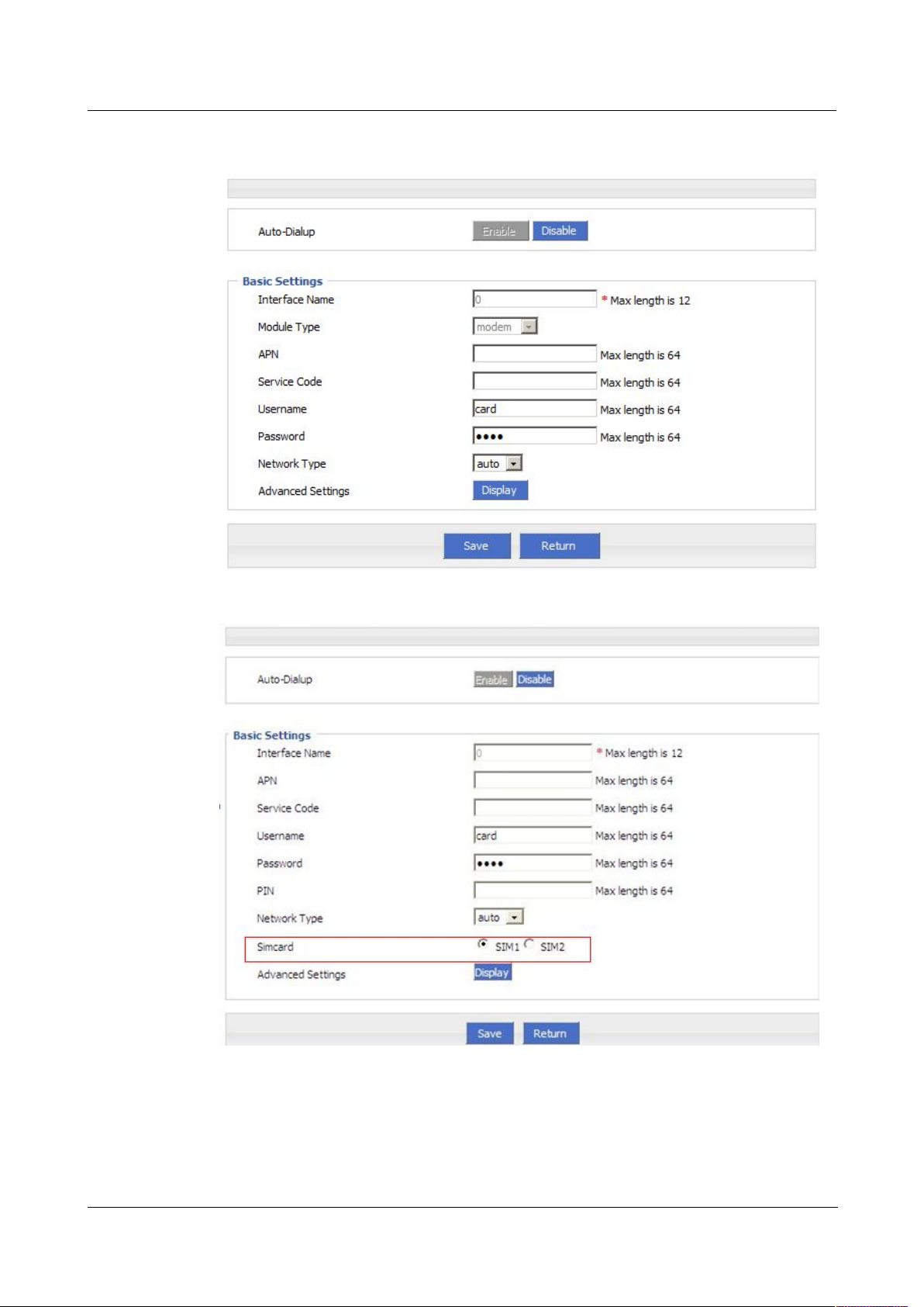
Figure 5-18 Single module single SIM/dual module dual SIM
Figure 5-19 Single module dual SIM
Version (2014-05-28) 7 -
7
Page 42
7 FAQ H792x 3G/4G Router
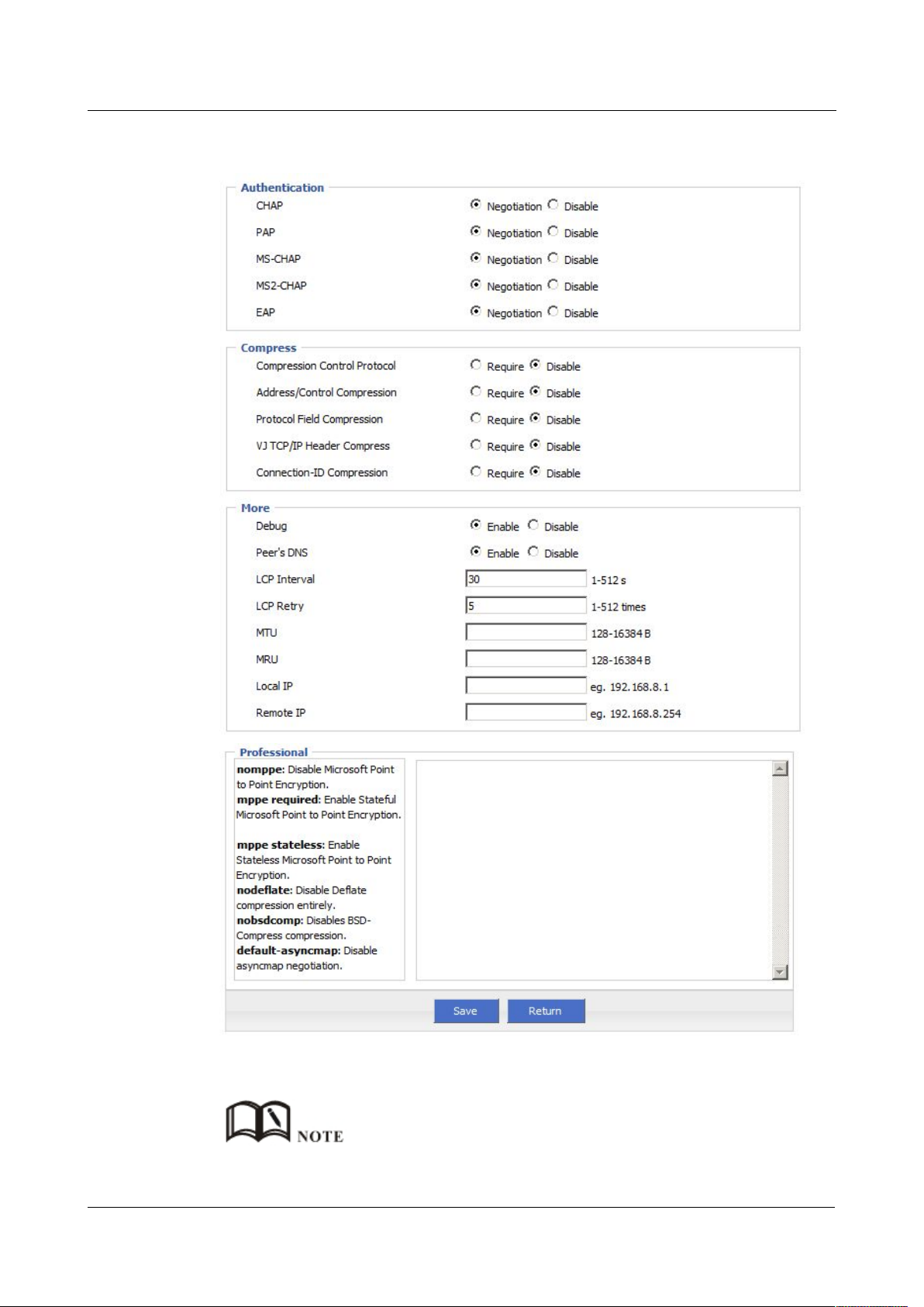
Figure 5-20 Advanced setting
3. Single click “save” icon to finish.
7 -
Grey icon means enabled.
8
(2014-05-28)
Page 43
H92x 3G/4G Router 7 FAQ
5.2.3 Parameter select
Step 1 Login H792x WEB GUI.
Step 2 Single click “Network > parameter select”.
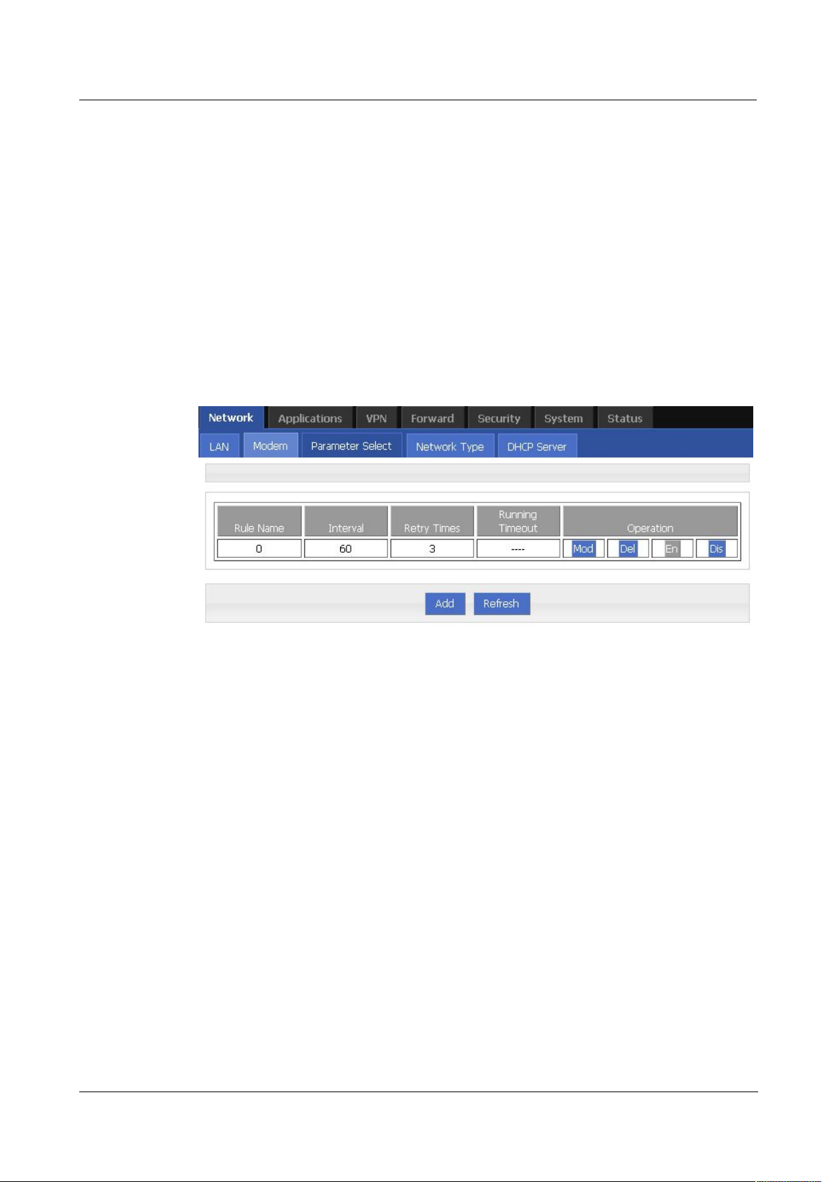
Figure 5-21 parameter select
Step 3 Add, modify, delete, enable and disable the parameter select rule.
add
---END
Router parameter select function is used for multi-function switch, like VPN parameter
switch, SIM parameter switch, multi-sever switch .etc. You could pre-config several network
parameter and switch between them. This function also could switch VPN setting, for
example, when modem 1 online it connect VPN 1, modem2 online it connect VPN2, they
cannot connect at same time because conflict, by this function you could easily switch when
network failure.
Version (2014-05-28) 7 -
9
Page 44
7 FAQ H792x 3G/4G Router
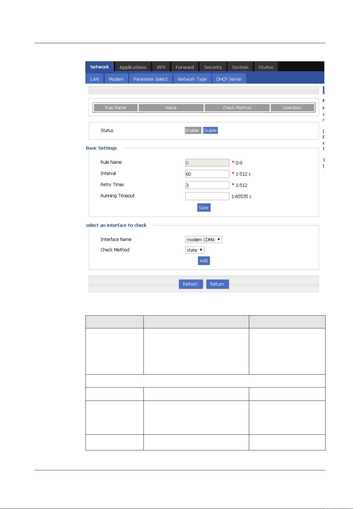
Figure 5-22 add rule
Table 5-6
Parameter instruction
Enable
Disable
7 -
10
Parameter Details Operation
Status For enabled rule: Only one rule is
running at one time, when it check
failed, next rule start running
For disabled rule: all related interface
also disabled
Basic settings
Rule name Name value decided running order
Interval/Retry
Times
Check interval and retry time, if all
check failed, switch to next rule
Value area :[0,9]
Value area :1~512
Units: seconds/time
Default: 60/3
Running timeout
Not available for rule 0
Value area:1~65535
This parameter restrict current rule
(2014-05-28)
Page 45
H92x 3G/4G Router 7 FAQ
state
icmp
5.2.4 Network type
Step 1 Login H792x WEB GUI.
Step 2 Single click “Network > Network type”.
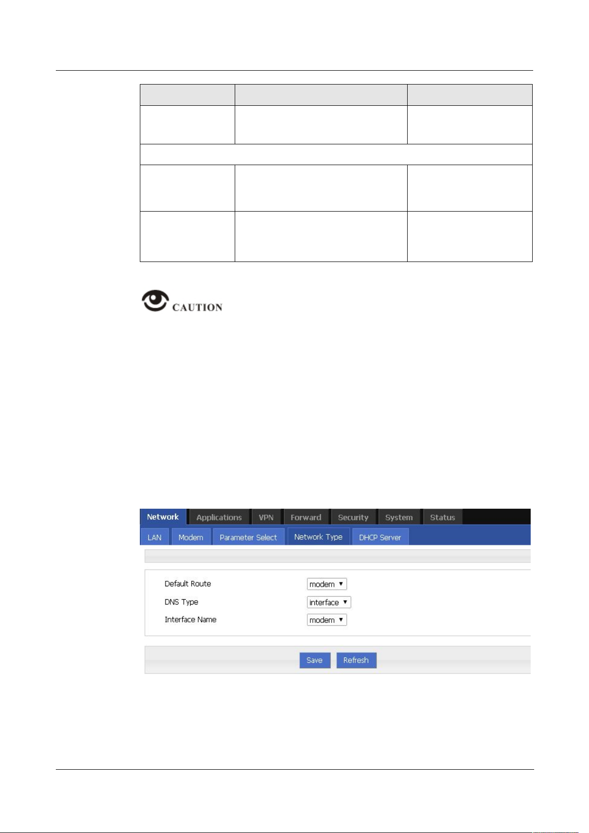
Figure 5-23 Network type window
Parameter Details Operation
running time, when timeout, switch
Units: seconds
to rule0, if do not set, switch to next
rule
Select a interface to check
Interface name Set related modem interface Dropdown List to choose,
current available option
will show below
Check method If state, router will check link state
Dropdown List
If ICMP, router will ping the ICMP IP
address to check
This function is control how the router online & offline, and use which modem to online.
Please notice timing task is execute a operation and keep the status, but parameter
select only execute a operation. So they do not conflict.
But Link backup function may conflict with parameter select function , if you set both,
final running result may not as you presume.
---END
Version (2014-05-28) 7 -
11
Page 46

7 FAQ H792x 3G/4G Router
Table 5-7
Network type Parameter instruction
interface
custom
Step 3 Single click “save” icon.
5.2.5 DHCP Service
Step 1
Login H792x WEB GUI.
Step 2 Single click “Network > DHCP Server”.
Parameter Details Operation
Default route Default route Dropdown List
Gateway modem Dropdown List
DNS type If Interface, will get DNS automatically Dropdown List
DNS1/DNS2 Manual set DNS Example: 8.8.8.8
Interface
name
Router will get DNS address from this
interface
Dropdown List
---END
DHCP (Dynamic Host Configuration Protocol) is a LAN network protocol, enable the DHCP
function, a function automatically can obtain the dynamic IP.
12
7 -
(2014-05-28)
Page 47
H92x 3G/4G Router 7 FAQ
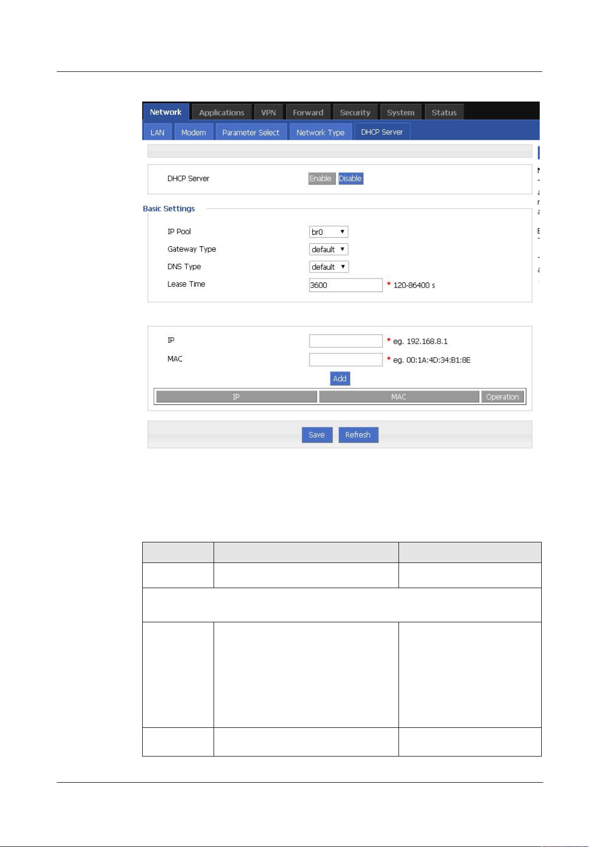
Figure 5-24 DHCP
Step 3 Configure DHCP parameter.
Table 5-8 DHCP Parameter
Enable
Disable
Basic Settings(DHCP is not recommended configure in the case of no special network
requirement)
br0
custom
DHCP parameter instructions as Table 5-8.
Parameter Details Operation
DHCP Server Enable or Disable DHCP feature
IP Pool The DHCP client can get the scope of IP
Dropdown List
address. When selecting interface
represents the interface of network
segment. This option is usually the need
to specify a machine configuration can
be assigned address range, for example:
only hope at most four machine can
automatically obtain the IP
Start IP When IP pool select custom
Manual input
configuration, configure the DHCP pool
Version (2014-05-28) 7 -
13
Page 48

7 FAQ H792x 3G/4G Router
default
modem
mdoem2
eth0
br0
custom
Parameter Details Operation
start IP address
Format:A.B.C.D/Mask
Example:192.168.8.2
End IP When IP pool select custom
configuration, configure the DHCP pool
end IP address
Gateway
Type
DHCP client access gateway IP source,
divided into default, br0, eth0, custom
four categories, associated interface, the
interface IP assigned to the DHCP client
as a gateway
DNS Type DHCP client access to the DNS IP
source, has a default, modem, modem2,
eth0, br0, custom and so on, generally do
not recommend to modify the
configuration, especially under the dual
mode application scenario configuration
is not recommended
Lease Time After the DHCP client obtain an IP on IP
lease time, the client usually renegotiate
obtain an IP address lease time in more
than half the time. IP lease time is
mainly used to release idle IP to avoid
that IP address resources are also
occupied after the DHCP client
shutdown
Manual input
Format:A.B.C.D/Mask
Example:192.168.8.254
Dropdown List
Default value:default
Dropdown List
Configuring for the default
is based on DNS address
which is allocated by the
router itself
Value area:120-86400
Units:seconds
Default value:3600
7 -
14
IP, MAC binding is used to assign a fixed MAC within the specified range of IP addresses
IP Paired with the specified MAC, when a
DHCP client which MAC is bound send
a DHCP request, the IP address
associated with the MAC address
Manual input
Format:A.B.C.D/Mask
Example:192.168.8.2
binding assigned to it. The IP address
assigned even if it has not been occupied
and not assigned to other MAC
addresses
MAC Configure DHCP to obtain an IP need to
specify the DHCP client's MAC address
WORD Type MAC Format
Example: 00:1A:4D:34:B1:8E
---END
(2014-05-28)
Page 49
H92x 3G/4G Router 7 FAQ
5.3 Application program configuration
5.3.1 ICMP check
Step 1
Log-on WEB GUI of H792x 3G/4G router.
Step 2
Click “applications > ICMP Check”.
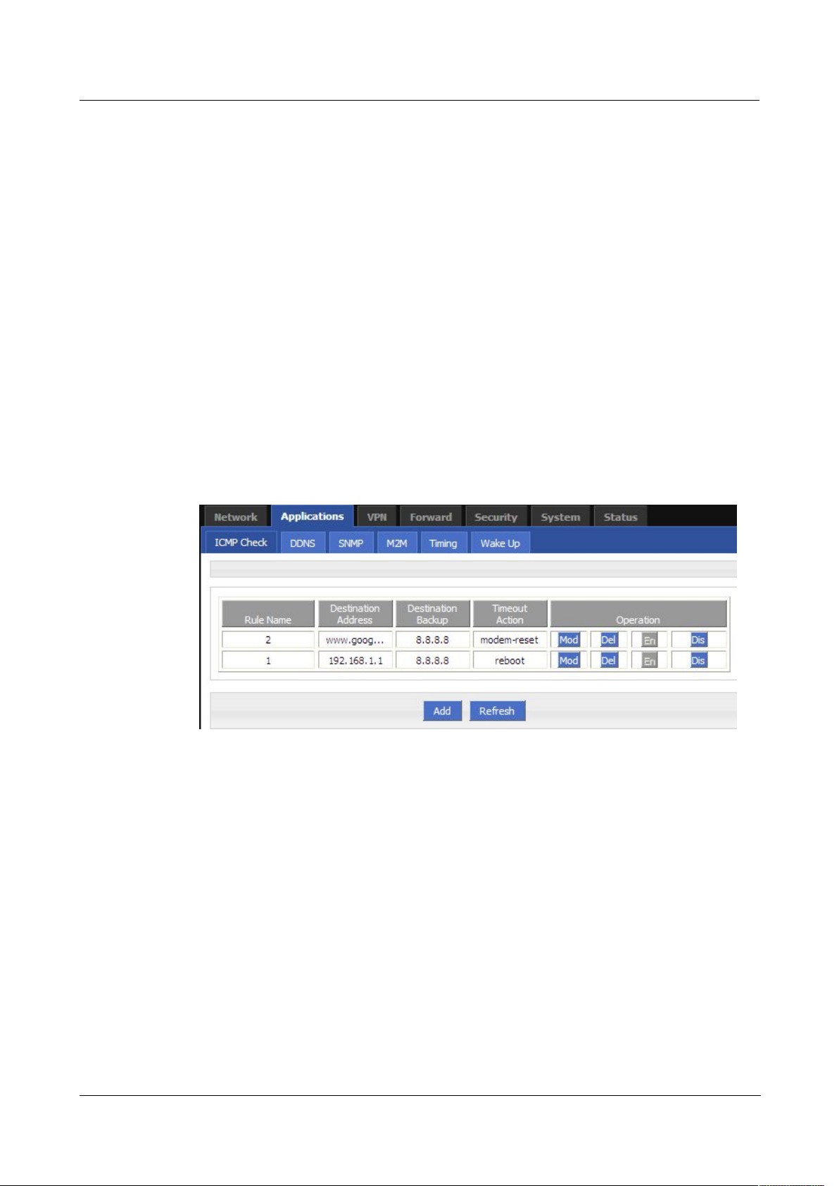
Figure 5-25
ICMP Check tab
Step 3 “Add”, “Modify”, “Delete”, “Enable” “Disable” the function of “ICMP Check”.
Add
Based on years of customers experience for different applications, besides SNMP, DDNS,
H792x 3G/4G router has developed many functions for wireless network equipment, such as
ICMP check, interface flow check function, M2M terminal management function, task
management function and waking on demand function.
There is fake link (can get IP after dialing, but cannot link to destination address). Usually
LCP is used to avoid this. Besides LCP, H792x 3G/4G router can use another more reliable
checking way ICMP which check the link by PING. When abnormal link is checked, the
preset action will be executed to recover the link and systems quickly. Initially ICMP is to
check wireless link, and now it can be used to check VPN link and supports simultaneous
check in different rules. It supports maximum 10 ICMP check rules.
Open “ICMP Check” tab.
Version (2014-05-28) 7 -
15
Page 50
7 FAQ H792x 3G/4G Router
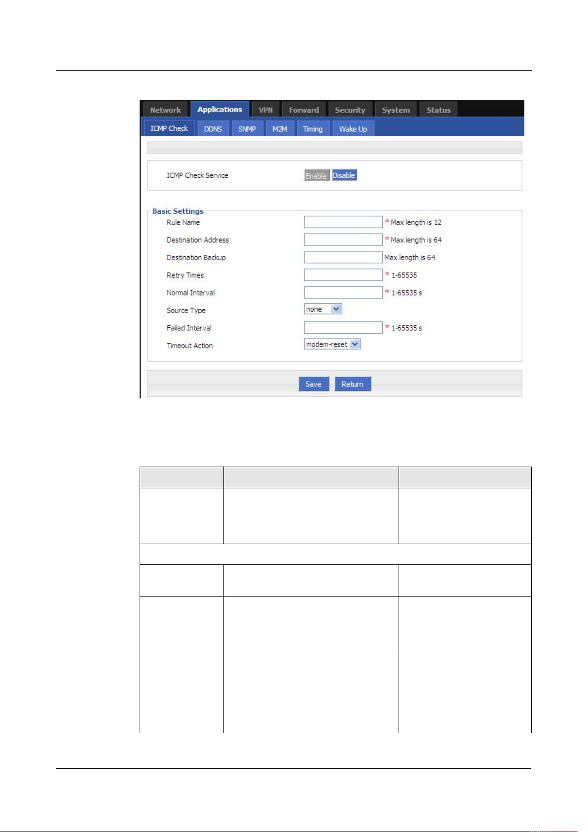
Figure 5-26 ICMP adding page
2. Configure the ICMP check parameter.
Table 5-9 ICMP check rules Parameter instruction
Enable
Disable
Parameter Details Operation
ICMP check
service
To enable or disable ICMP check
rules, multiple rules can be used
Button
simultaneously, and one specific rule
can be disabled
Basic Config
Rule Name ICMP Check rule name, just to
WORD type, max 12 bytes
distinguish different rules
Destination
address
Destination address of ICMP check,
can be domain name and also can be IP
WORD type, max 64 bytes
address. If domaine name, DNS of the
router shall be configured correctly
Destination
backup
A backup destination address of ICMP
check, if “destination address” cannot
WORD type, max 64 bytes
be linked by ICMP check, the
“destination backup” address will be
checked, if still cannot linked, the
router will recognize ICMP check fails
7 -
16
(2014-05-28)
Page 51

H92x 3G/4G Router 7 FAQ
br0
modem
Dropdown List options
modem-reset:modem
redials
reboot:router reboots
custom:customized action
3. Single click “save” to finish a ICMP check rule.
Modify
Delete
Enable
Disable
Refresh
5.3.2 DDNS configuration
Parameter Details Operation
Retry
times/normal
interval
Check time interval and max check
failure times when link is OK, if check
failure times reaches the max times,
then “timeout action ” will be
executed, e.g “modem reset”
Source Interface Router sends an ICMP detected
packet's source address
Timeout action
An action when check failure times
reach max failure times. Can be
modem-reset, reboot, custom
Run commands If “Timeout action” is “custom”, this
shall be comfigured. Commands are
BGO operation. It is not suggested to
use, if need, pls contact our technical
engineers
Value area :1~65535
Unit: second/time
Dropdown List options
WORD type, max 64 bytes
If ICMP is normal, ICMP packet is sent at “normal interval”. When abnormal, packet will be sent
continuously at “failed interval”. If “destination address” cannot be linked and checking times reach
“retry times”, “destination backup” will be checked. if “destination address” can be linked in checking
“destination backup”, “destination address” will be checked again. If “destination backup” cannot be
linked and checking times reach “retry times”, “Timeout action” will be executed.
If already enabled, the button “EN” is gray.
If already disabled, the button “DIS” is gray
Click “refresh” to refresh the page.
---END
Version (2014-05-28) 7 -
Network of SIM/UIM shall be a public address so that router can be visited for a DDNS.
17
Page 52
7 FAQ H792x 3G/4G Router
Step 1 Log-on WEB GUI of H792x 3G/4G router.
Step 2 Click “Applications” > “DDNS”.
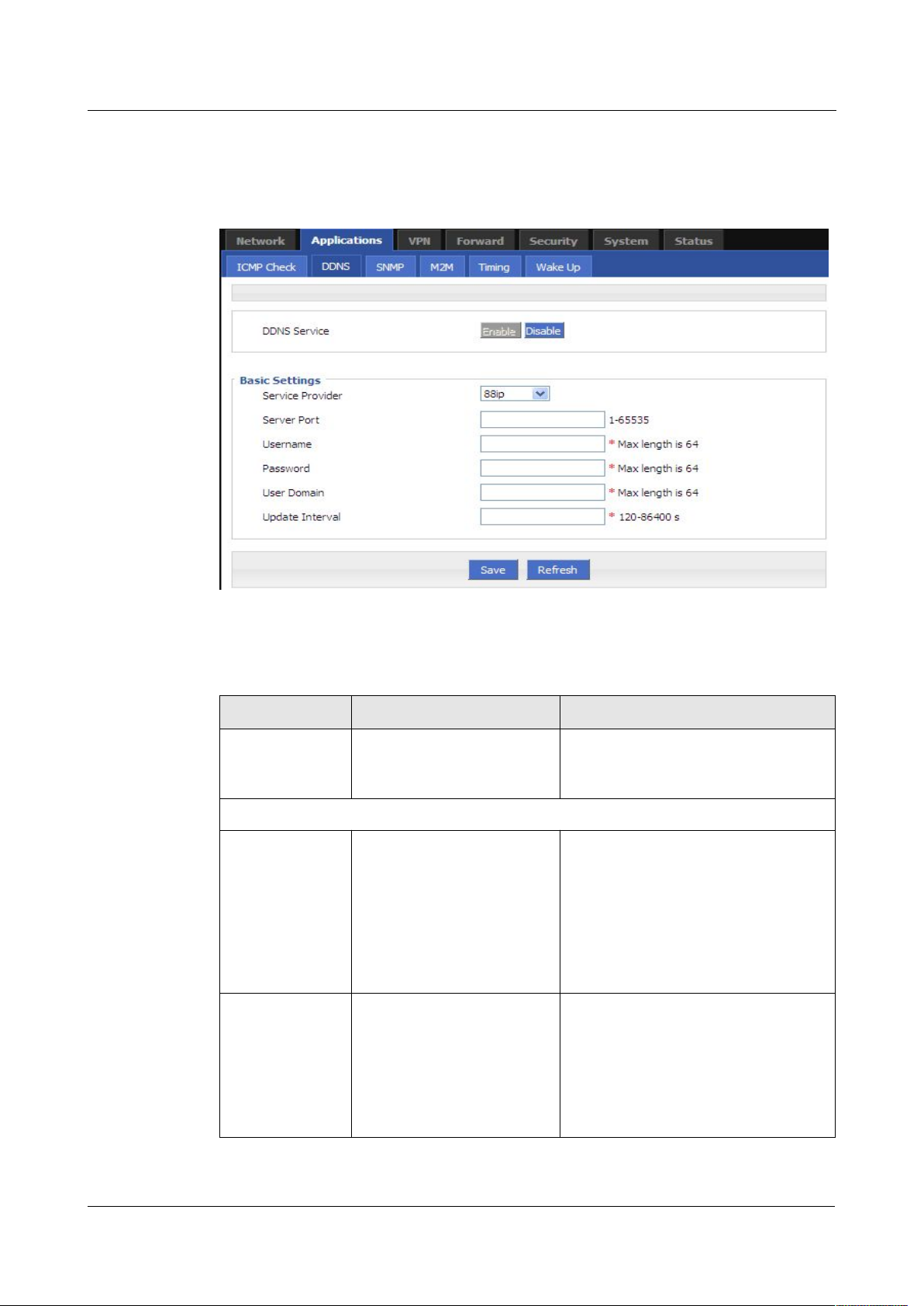
Figure 5-27
DDNS configuration
Step 3 Configure DDNS parameter.
Table 5-10 DDNS Parameter instruction
Enable
Disable
3322
88ip
Dnsexit
Dyndns
Zoneedit
changeip
custom
Parameter Details Operation
DDNS Service Set whether enable DDNS
Button
service function
Basic Config
Service Provider Select the DDNS service
Dropdown List options
provider that router currently
supports, don’t support other
providers
Server IP or
Domain
When “custom” in “service
provider” is selected, “Server
IP or Domain” will be
configured. Default is
WORD type, max 64 bytes
standard DDNS protocol. for
customized protocol, please
contact our engineer
7 -
18
(2014-05-28)
Page 53

H92x 3G/4G Router 7 FAQ
Step 4
Click “save”to complete DDNS configuration
5.3.3 SNMP configuration
Step 3 Log-on WEB GUI of H792x 3G/4G router.
Step 4 Click “Applications > SNMP” to open the “SNMP” tab.
Parameter Details Operation
Server Port Set the port number of the
DDNS server provided by
the service provider. The
Value area: 1~65535
If empty, it means 80 port
default port number is 80
User
name/Password
Set user name/password of
the DDNS service registered
Normal WORD type/CODE type, max
64 bytes
in the service provider
User Domain Set the domain of the DDNS
Normal WORD type, max 64 bytes
service provided by the
service provider
Update Interval Set the interval of the DDNS
client obtains new IP,
suggest 240s or above
DDNS in China: 88IP (www.88ip.net), 3322 (www.3322.org)
DDNS outside of China: DNSEXIT (www.dnsexit.com), ZONEEDIT(www.zoneedti.com),
CHANGEIP(www.changeip.com), DYNDNS(www.members.dyndns.org)
Afer router reboots, IP address which SIM/UIM gets from ISPs will change. If user uses DDNS in
remote login, no matter the IP address changes, he can Log-on the router.
Value area: 120~86400
Unit: seconds
---END
SNMP(Simple Network Management Protocol)can monitor routers remotely and get to know
the status of routers (Support interface status check, like VPN, modem etc. MIB of our
company shall be used).
Version (2014-05-28) 7 -
19
Page 54
7 FAQ H792x 3G/4G Router
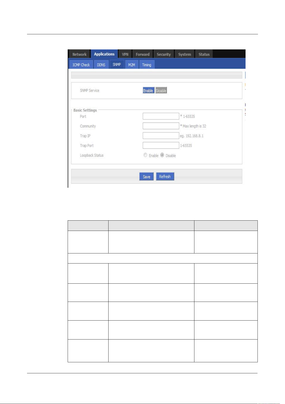
Figure 5-29 SNMP configuration
Step 5
Configure SNMP parameter.
Table 5-11 SNMP Parameter instruction
Enable
Diable
Enable
Diable
Parameter Details Operation
SNMP service To enable or disable SNMP service Options:
Basic Config
Port SNMP port, suggest to be default
port161
Community Community Password of SNMP client
Value area: 1~65535
Default: 161
WORD type, max 16 bytes
to router SNMP, Used for identification
Trap IP Link-state router report server address Manual input
Format:A.B.C.D/Mask
Trap Port Link-state router report server
address’s port
Loopback Status Match with "LAN" page loopback
Value area:1~65535
Default:162
Options:
address, in the "Loopback Status" to
"Enable", means loopback address
7 -
20
(2014-05-28)
Page 55

H92x 3G/4G Router 7 FAQ
Step 6
Single click “save” icon to finish SNMP configuration.
5.3.4 M2M configuration
Step 3 Log-on WEB GUI of H792x 3G/4G router.
Step 4 Click “Applications > M2M” to open M2M configuration tab.
Parameter Details Operation
configuration successfully, the router
reported Trap IP packet source address
is the loopback address, If the
"Loopback Status" to "Disabled" means
router IP packet source address for the
LAN port address
MIB for SNMP can be downloaded from our website, if necessary, please contact our technical
engineers.
---END
H792x 3G/4G router has embedded a WMMP (Wireless Machine-to-Machine Protocol)
protocol to realize communication with M2M (Machine-to-Machine) platform which can
remotely monitor and manage the routers and its network, e.g. visit the router, patch
upgrading, firmware upgrading, parameter configuration, monitor the network strength, time
delay, flow. Its configuration is as follows:
Version (2014-05-28) 7 -
21
Page 56
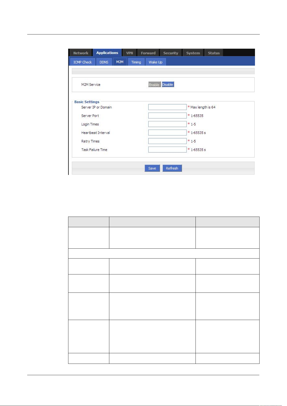
7 FAQ H792x 3G/4G Router
Figure 5-30 M2M configuration
Step 5 Configure M2M parameter .
Table 5-12 M2M Parameter instruction
Enable
Disable
Parameter instruction is shown.
Parameter Details Operation
M2M service To enable or disable M2M function.
Button
This function shall be used with our
M2M platform
Basic Config
Server IP or
Domain
Server Port WMMP port No, shall be the same with
Set the server IP or domain of M2M
platform
Normal WORD type, max
64 bytes
Value area: 1~65535
Port No of M2M platform server
Login Times Max retry times of router to login M2M
platform. If login times reach max
times, the router will reboot, M2M will
Value area: 1~5
Unit: times
initialize and login again
Heartbeat
Interval
Time interval to send heartbeat which
maintain the like with M2M platform
server. The heartbeat includes the
Value area: 1~65535
Unit: seconds
network status info which will update
the network info of the M2M platform
7 -
22
Retry Times There is a retry mechanism for package
Value area: 1~5
(2014-05-28)
Page 57
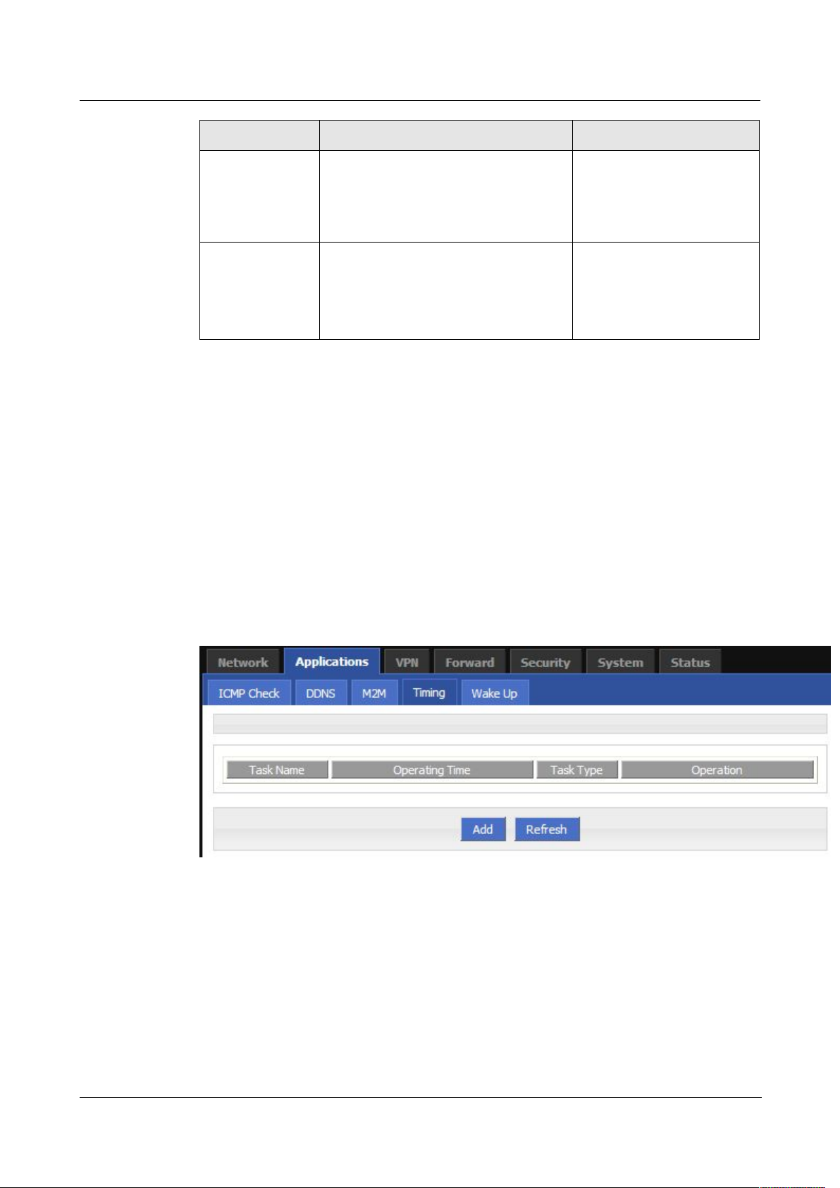
H92x 3G/4G Router 7 FAQ
Step 6 Single click “save” icon to finish the configuration.
5.3.5 Timing configuration
Step 3
Log-on WEB GUI of H792x 3G/4G router.
Step 4 Click “Applications > M2M” to open M2M configuration tab.
Figure 5-31
Timing configuration
Step 5 To add a timing task, please click “Add”.
Parameter Details Operation
exchange between router and M2M
platform. When exchange times reach
retry times, router will judge the
exchange fails and usually no operation
will be made
Task Failure
Time
---END
This application is to control the online time of the router to better manage network and save
3G/4G flow. H792x can add several online period as per the user’s requirement (e.g. hours of
some day). in addition, this application can support to begin some tasks at a time point (e.g
redial or reboot at 00:00). Max 10 tasks.
The time to judge an exchange fails, if
an exchange uses time which exceeds
the “task failure time”, router will judge
the exchange fails and will retry to send
the exchange
Unit: seconds
Value area: 1~65535
Unit: seconds
Version (2014-05-28) 7 -
23
Page 58
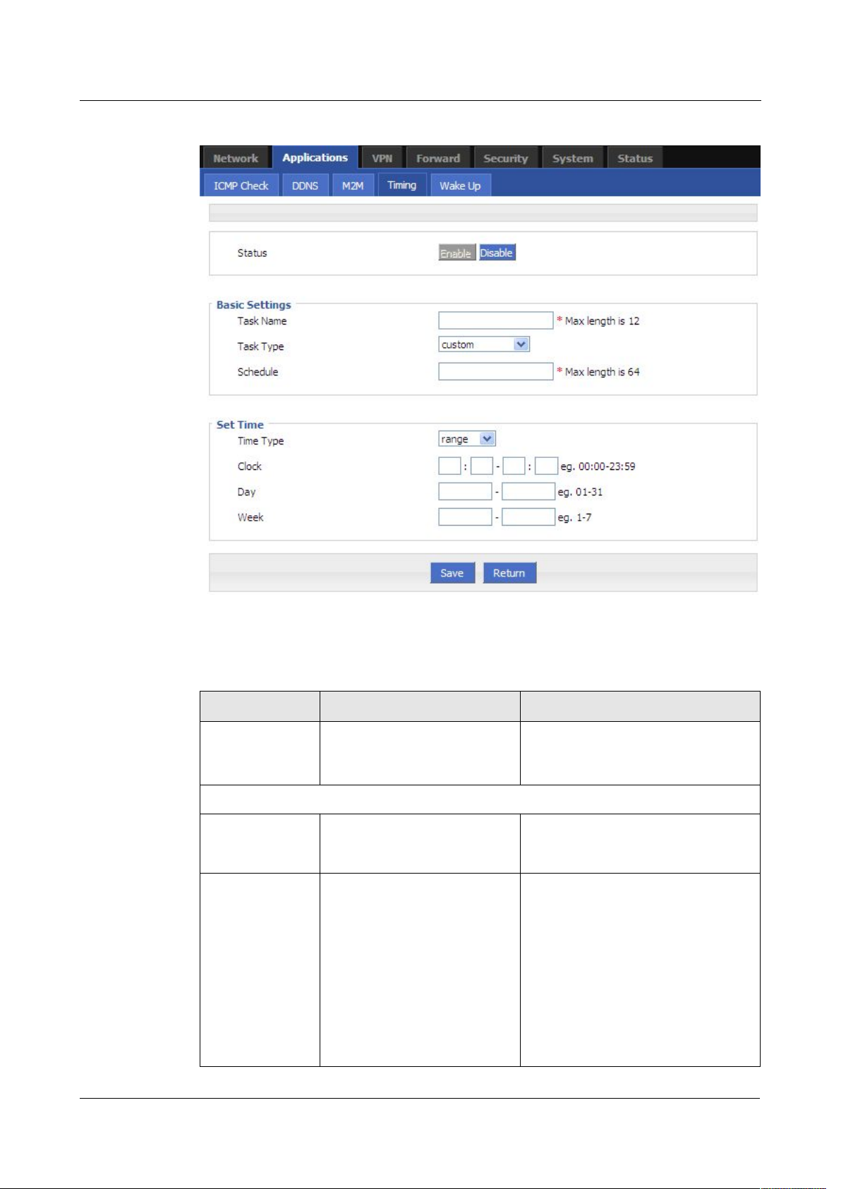
7 FAQ H792x 3G/4G Router
Figure 5-32 To add timing task
Step 6 Configure timing task parameter.
Table 5-13 Timing task parameter instruction
Enable
Disable
modem-online
modem2-online
reboot
custom
7 -
24
Parameter Details Operation
Status To enable or disable a timing
options
task. Some task shall be
enabled together with NTP
Basic Config
Task name Name of a timing task Max 12 digits
Task type Task type has action task and
Drop DownList options:
status task. Action task is for
time point or time interval,
while status task is for time
period (for “modem-online”
and “modem2-online”), which
means that the modem will be
online (if down, modem will
automatically redial) during
the configured time period.
if select “custom”, “schedule” will be
shown to input command (can be
dialup or other command). Max 64
bytes
Modem will be offline (no
(2014-05-28)
Page 59

H92x 3G/4G Router 7 FAQ
range
interval
Step 7
Single click “save” icon to finish “Timing” configuration
5.3.6 Wake up configuration
Step 3
Log-on WEB GUI of H792x 3G/4G router.
Step 4
Click “Applications > Wake up” to open “Wake up” tab.
Parameter Details Operation
dialing) for other time
Schedule This is linux shell command.
WORD type. Max 64 digits
Usually suggested not to use
it. In case of need, please
contact our technical engineers
Set time
Time type Range or interval for status
Dropdown List options:
task or action task
When “time type” select “range”
Clock To input hour and minute.
When beginning and end hour
Value area: [00:00,23:59]
Format: HH:mm-HH:mm
and minute are the same, it
means a time point for action
task
Day Days in a month for task Value area: [01,31]
Format: XX-XX
Week Days in a week for task. When
“day” and “week” are both
Value area: [1,7]
Format: X-X
input, it means only if both
conditions meet, the task will
1 for Monday
begin
When “time type” select “Interval”
Interval Time interval for action task
Value area: 1~65535
Unit: minutes
When “range” is selected, NTP shall be enabled . when “interval” is selected, no such
requirement. For “NTP” configuration
---END
3G/4G fee is mostly based on flow. H792x 3G/4G router can get on/off line on demand. It
supports on/offline or reboot triggered by voice, SMS or data. It supports max 10 cellphone
Nos.
Version (2014-05-28) 7 -
25
Page 60
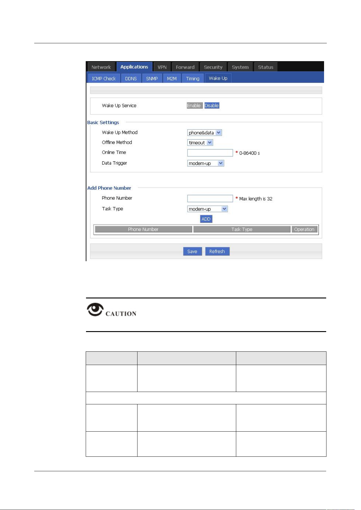
7 FAQ H792x 3G/4G Router
Figure 5-33 Wake up configuration
Step 5
Configure “wake up” parameter.
Table 5-14 Wake up Parameter instruction
Enable
Disable
modem-down
7 -
26
After finish “basic setting” parameter, click “save” to save it in the flash memory.
Parameter Details Operation
Wake up service To enable or disable the service. Options:
Add phone Number
Phone Number Phone No to trigger the router
WORD type. Max 32 digits.
action. One phone No for one
action of one modem.
Task type
Triggered action includes
Dropdown List options
modem-up, modem-down,
reboot.
(2014-05-28)
Page 61

H92x 3G/4G Router 7 FAQ
modem-up
modem2-down
modem2-up
reboot
phone/data
phone
timeout
idle
modem-up
modem2-up
modem-all-up
Step 6 click “ADD” to add a new wake up rule.
Parameter Details Operation
Basic setting
Wake up method To configure actions triggered, it
supports phone and data. If choose
phone, please be sure that the SIM
card has opened voice or SMS
service. Usually recommend voice
wakeup with high efficiency and
don’t need SMS charge.
Offline method Support “timeout” and “idle”.
“timeout” means router will get
offline once time reaches the
configured time commencing from
online time. “idle” means if idle (no
data transmission) time is as long as
the configured time, the router will
get offline.
Online time Online time of router, for “idle”,
online time will recalculated if
there is data transmission.
Data trigger Configured as wakeup by data.
When router receives data from
external network, the modem will
be triggered to be online, LAN data
and broadcast data will not trigger
actions. If configured as
“phone&data”, either phone or data
can trigger actions
Dropdown List options
Dropdown List options
Value area :0~86400
Unit: second
Dropdown List options
After add a new rule, the rule will be shown on the bottom. To click “Del” to delete the rule.
Version (2014-05-28) 7 -
27
Page 62
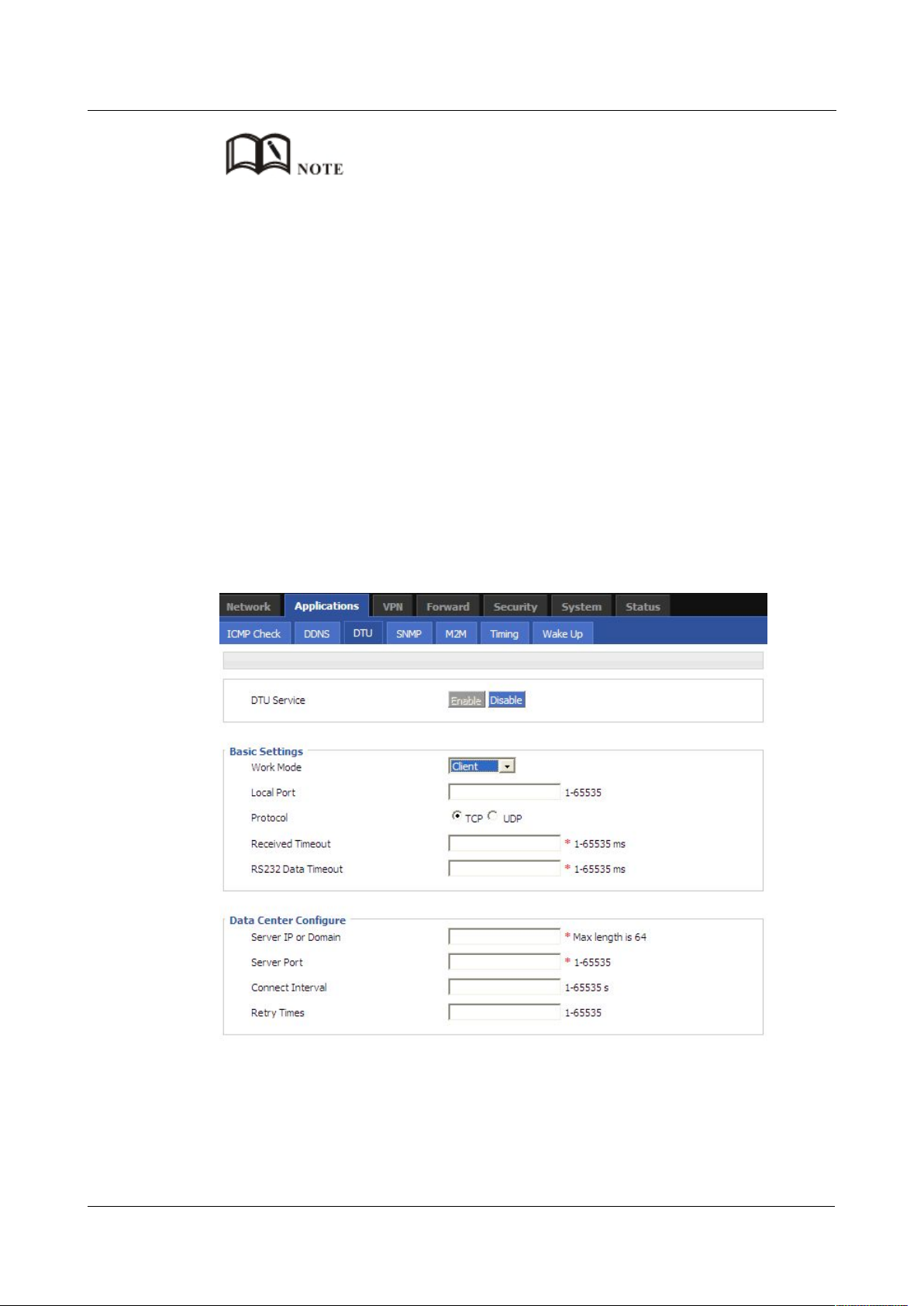
7 FAQ H792x 3G/4G Router
5.3.7 DTU configuration
Step 3 Log-on WEB GUI of H792x 3G/4G routers.
Step 4 Click “Applications > DTU” to open “DTU” tab.
Figure 5-34
DTU configuration
One phone number be set for actions of different modems, but cannot be set as different actions of one
modem.
It’s OK for either SIM of the two SIMs of H792x 3G/4G router to open SMS or voice function, no
matter which slot to be installed.
“Data” will trigger only actions: modem-up/modem2-up/modem-all-up
If “online time” is set as 0, it means router will be always online. To get the router offline, pls choose
actions to trigger offline.
“Online time” in “wake up” will affect other functions like SIM switch, network backup, task
management. So when users set wakeup parameter, please note whether there is conflict with other
factions.
Voice trigger: router will begin the action after 5 seconds of the sound “du”.
DTU(Data transfer Unit)is to transfer data for meters with RS232 interface from site to center
through 3G/4G network. It support TCP/UDP Client/Server mode.
28
7 -
(2014-05-28)
Page 63
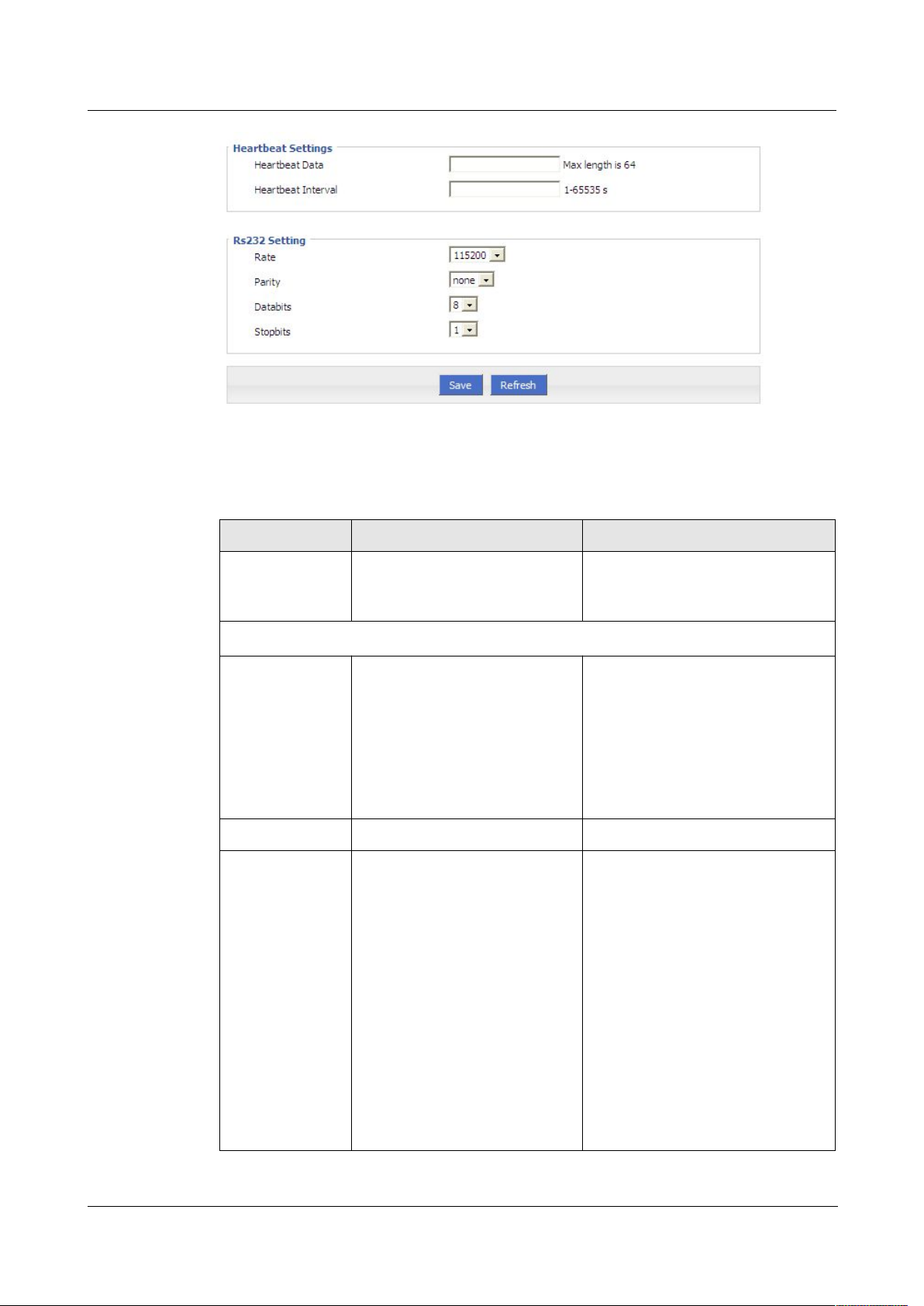
H92x 3G/4G Router 7 FAQ
Step 5
Configure “DTU” parameter.
Table 5-15 DTU Parameter instruction
Enable
Disable
Server: 3G/4G router act as
Client: 3G/4G router act as
DDPClient: 3G/4G router act
Server
Client
DDPClient
Parameter Details Operation
DTU Service Enable or Disable DTU Service DTU Service options
Basic Settings
Work Mode Work mode:
Select from Dropdown List
TCP/UDP server
TCP/UDP client
as UDP client with Hongdian
protocol
Local Port DTU service port Specify the port number:1-65535
Protocol Protocol of TCP/UDP
connection
TCP protocol is a
connection-oriented reliable
transport protocol for high
reliability requirements and for
Select protocol:TCP or UDP
Note:
When the work mode is "DDP
clients," only support "UDP
protocols used in conjunction with
the DDP protocol.”
communication efficiency
which is not
high degree of sensitivity of the
occasion
UDP protocol is a
connectionless unreliable
transport protocol, suitable for
relatively high efficiency
requirements, and the occasion
Version (2014-05-28) 7 -
29
Page 64

7 FAQ H792x 3G/4G Router
Format : A.B.C.D/Mask or Word
Type
Parameter Details Operation
of relatively low reliability
Received
Timeout
RS232 Data
Timeout
DTU port timeout which receive
from the data center, within the
received packet does not exceed
the maximum packet length
range, the data is reading at this
time, if the data is been reading,
and will display all data during
this time; If no data,when it is
greater than the timeout, it will
consider reading data
completely, displays DTU serial
terminal
DTU waiting time to send the
serial data to the data center
side. Within waiting time, the
data sent over UDP / TCP
packets received maximum
packet length, then sent
immediately; if not more than
UDP / TCP packets received
maximum packet length, then
wait for data until it reaches the
last packet idle time , and then
to send
Specify time according to your
need
data:1-65535ms
Default value:500
Units:ms
Specify time according to your
need
data:1-65535ms
Default value:500
Units:ms
Data Center Configure
Server IP or
Domain
Server Port DataServerCenter(DSC) port
DataServerCenter(DSC) ip or
domain
Port number:1-65535
number
Connect Interval The reconnect interval is DTU
client fail to connect to DSC
Manually input:1-65535
Units:second
server
Retry Times The retry times is DTU client
Manually input:1-65535
fail to connect to DSC server
Heartbeat Settings
Heartbeat Data customize heartbeat data content Manually input,Max length is 64
Heartbeat
Interval
Set heartbeat interval(when
there is no data transfer, the
Manually input:1-65535
Units: second
router send the heartbeat data
content every heartbeat interval)
RS232 settings
Rate Set the serial port transfer rate Select from the dropdown list,
according to the practical settings
30
7 -
(2014-05-28)
Page 65

H92x 3G/4G Router 7 FAQ
Step 6 Single click “save” icon to finish “DTU” configuration,
5.4 Security
5.4.2 Overview
5.4.3 Configuration
Step 3 Log-on WEB GUI of H792x 3G/4G router.
Step 4 Click “Security > IP Filter” to open “IP Filter” tab.
Parameter Details Operation
of DTU serial port
Default: 115200
Parity Set the data parity Select from the dropdown list,
according to the practical settings
of DTU serial port
Value: None, Old ,Even
Default: None
Databit Set the data transfer bit Select from the dropdown list,
according to the practical settings
of DTU serial port
Value: 5,6,7,8
Default: 8
Stopbit Set the data stop bit Select from the dropdown list,
according to the practical settings
of DTU serial port
Value: 1,2
Default: 1
IP Filter
DTU will start to work when modem is online if it is enabled.
---END
“Security” will control where the data can pass through by analyzing IP address and port of
ICMP, TCP/IP package from the destination end or source end. H792x 3G/4G router supports
IP filter, domain filter and MAC filter.
IP filter refers to judgment whether to allow router to forward the data according to filter rules,
thus to manage internet surfing of PC in LAN. IP filter is used to allow part of PCs in LAN to
visit external WAN network or forbidden some PCs from visiting specific website.
Version (2014-05-28) 7 -
31
Page 66
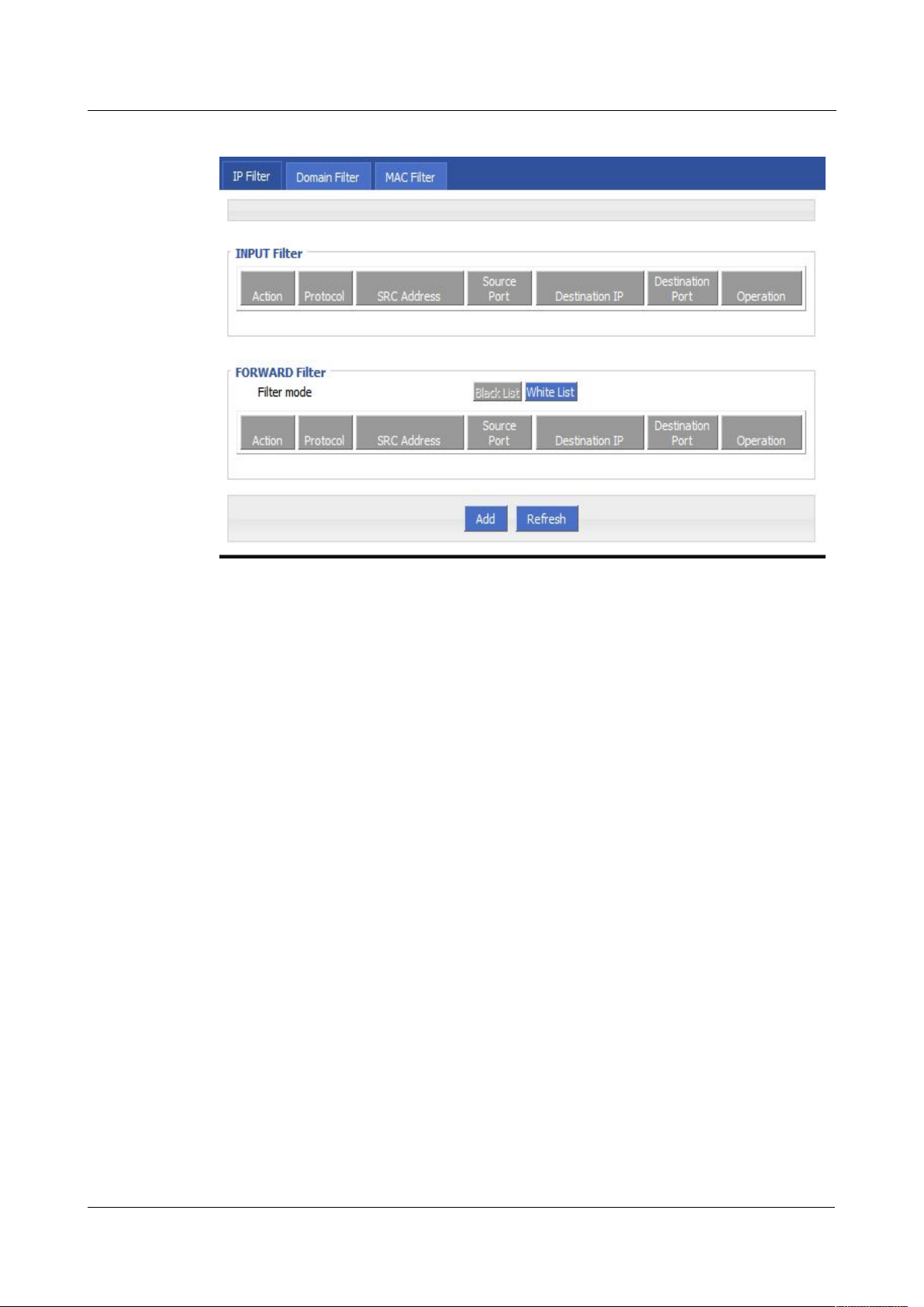
7 FAQ H792x 3G/4G Router
Figure 5-35 IP Filter tab
Step 5 In the forwarding filtering rules.
Black List:The default allows packet forwarding, in line with the list of "discarded" rules
White List:The default refuses packet forwarding, in line with the list of "accept" rules
Step 6
Click “Add” to add a new IP filter rule and configure IP filter parameter. There are two types
packet cannot be forwarded through the router.
packet can go through router forwarding.
of IP filter: “Input” and “Forward”. To add a rule.
7 -
32
(2014-05-28)
Page 67
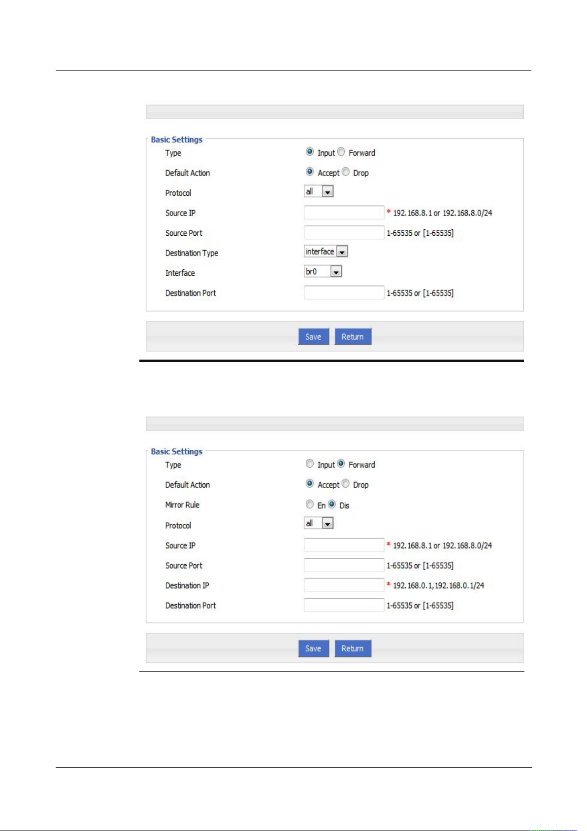
H92x 3G/4G Router 7 FAQ
Figure 5-36 IP filter “Input” type
Figure 5-37
IP Filter “Forward” type
Version (2014-05-28) 7 -
33
Page 68

7 FAQ H792x 3G/4G Router
Table 5-16 IP filter parameter instruction
Dropdown List options
all
tcp
udp
icmp
interface
any
br0
modem
modem2
eth0
eth1
Parameter Details Operation
Type Select a filter type, you can choose
according to their needs, "Input" or
"Forward"
Input: whether to allow access to the
router
Forward: whether to allow the router
forwarding
Default Action The default action rule. You can select
"Accept" or "discard"
Accept: firewall to accept the package,
which can be passed
Discard: firewall discards the packet
directly
Mirror Rule When the filter type select "Forward", it
needs to be configured
Enable: On the basis of the
configuration rules to add an extra
source address/port and destination
address/port reverse the rules
Disabled: no treatment
Dropdown List options
Dropdown List options
Dropdown List options
Protocol Protocol used by IP packets
Source IP
The source IP address of the packet
Source Port The source Port of the packet, when the
protocol choose "icmp", it don’t need
to configure
When the IP Filter type select “Input”
Destination Type Design an IP packet access router
interface
Interface Configure when Destination Type
select “Interface”, means the IP packet
access the router interface
Manual input
Format:A.B.C.D/Mask
Value area: 1-65535 or
[1-65535], it can be a range,
or a single port
Dropdown List options
Dropdown List options
7 -
34
(2014-05-28)
Page 69
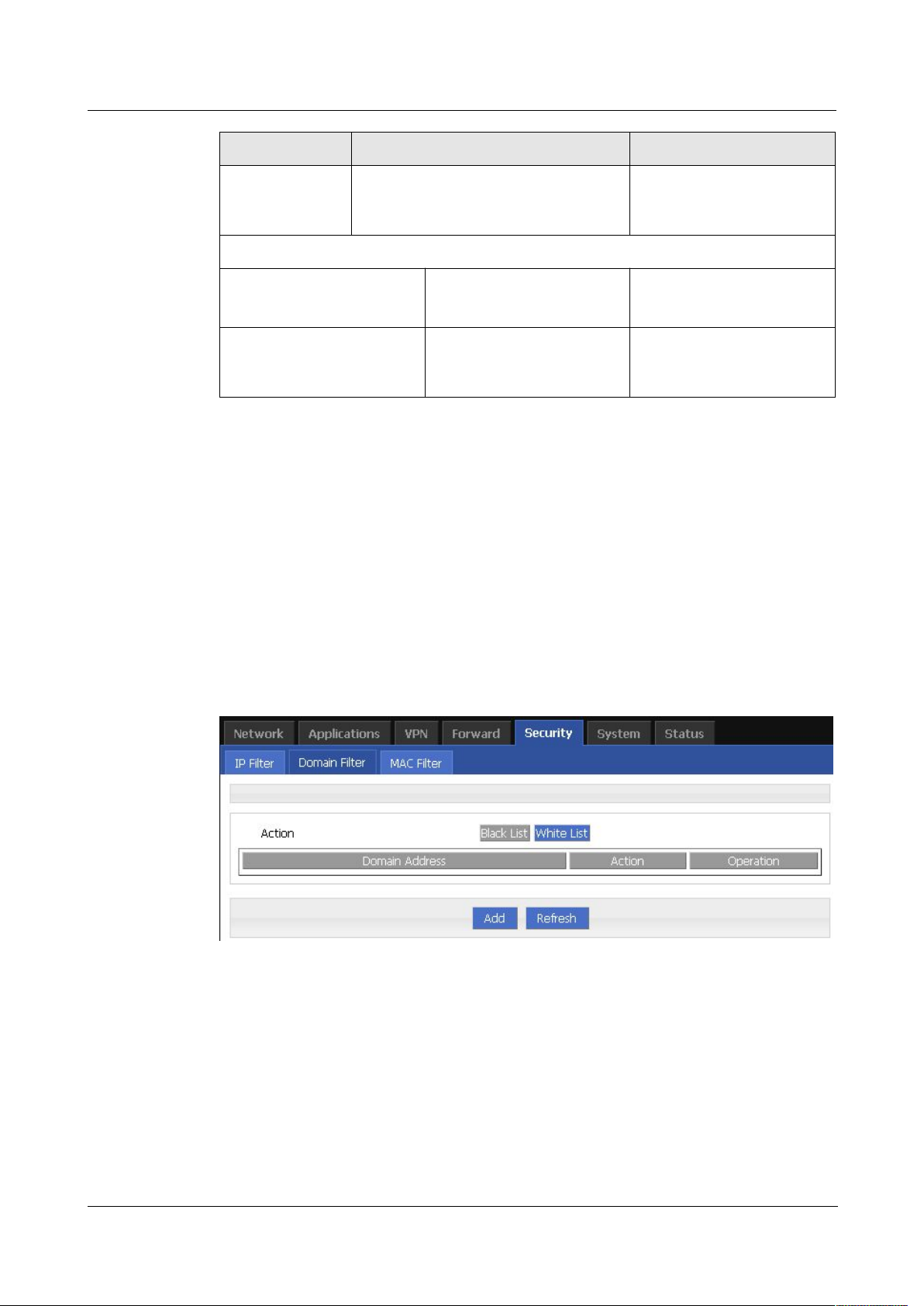
H92x 3G/4G Router 7 FAQ
Step 7
Single click “save” to finish.
Step 3
Log-on WEB GUI of H792x 3G/4G router.
Step 4
Click “Security > Domain Filter” to open “Domain Filter” tab.
Figure 5-38 Domain filter tab
Black list: websites in the blacklist cannot be visited. Click “black list” to forbid visiting the
White lis: only the websites in the white list can be visited, while other websites cannot be
Step 5
Click “ADD” to add a new domain filter rule and configure domain filtering parameter.
Parameter Details Operation
Domain Filter
Destination Port IP packet access router ports (when the
protocol select "icmp", requires no
configuration)
Value area: 1-65535 or
[1-65535], it can be a range,
or a single port
When the IP Filter type select “Forward”
Destination IP IP packet destination IP Manual input
Format:A.B.C.D/Mask
Destination Port IP packet destination port Value area: 1-65535 or
[1-65535], it can be a range,
or a single port
--END
Domain filter support black list and white list. It is used to forbid PCs in LAN from visit some
websites or allows them to visit specific websites.
websites in the list.
visited. Click “White list” to activate it.
Version (2014-05-28) 7 -
35
Page 70
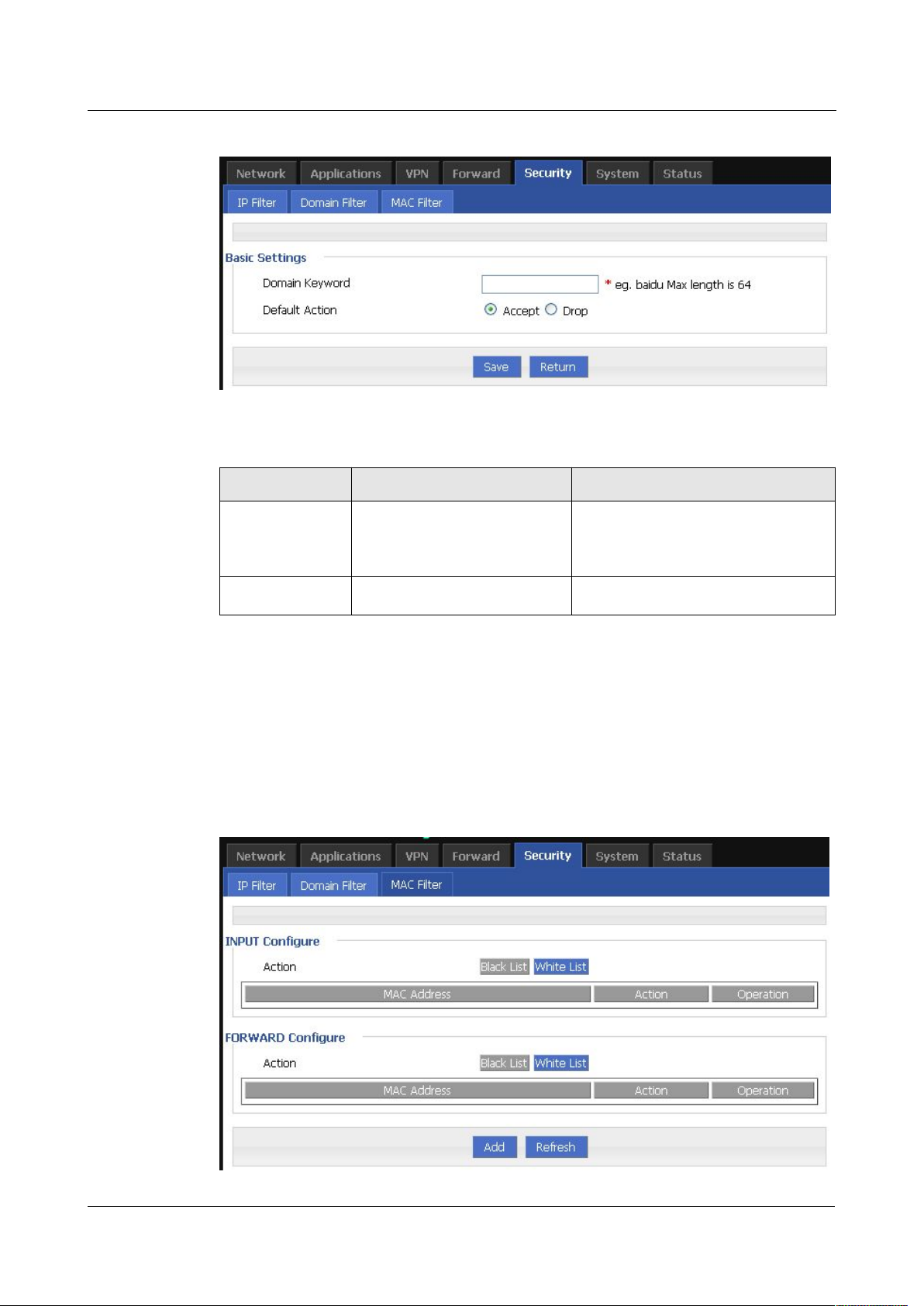
7 FAQ H792x 3G/4G Router
Figure 5-39 Domain filter tab
Table 5-17 Domain Filter parameter instruction
Accept.
Drop
Step 6
Single click “Save” to finish configuring a rule.
Step 3
Log-on WEB GUI of H792x 3G/4G router.
Step 4
Click “Security > MAC Filter” to open “MAC Filter” tab.
Figure 5-40
MAC Filter tab
Parameter Details Operation
Domain keyword Keyword of domain for filter WORD type, max 64 digits.
E.g. www.google.com, the keyword
is “google”.
MAC Filter
Default action Actions to filter the keyword
---END
7 -
36
(2014-05-28)
Page 71
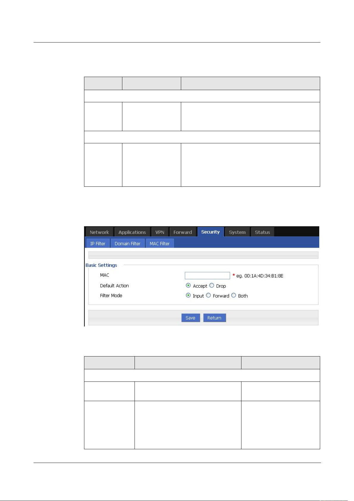
H92x 3G/4G Router 7 FAQ
Table 5-18 MAC Filter explanation
Blacklist: rules in blacklist cannot visit router,
White list: rules in white list can visit router, other
Blacklist: rules in blacklist cannot visit external
White list: rules in white list can visit external
Step 5 Click “Add” to add a new MAC filter rule and configure MAC filtering parameter.
Figure 5-41
MAC Filter configuration
Table 5-19 MAC Filter Parameter instruction
Accept: to accept all packages from
Drop: to drop all packages from this
Parameter Details Operation
Input configuration
Action To activate MAC
input filtering black
list / white list.
Forward configuration
Action To activate MAC
forward filtering
black list / white list.
other MACs can visit router.
MACs cannot visit router.
network, other MACs can visit external network
through router.
network, other MACs cannot visit external
network through router.
Parameter Details Operation
Basic Settings
MAC MAC to be filtered WORD type MAC format:
XX:XX:XX:XX:XX:XX
Default Action Default actions of the rule. Can be
“accept” or “Drop”:
To choose “accept” or
“Drop”
this MAC.
MAC.
Version (2014-05-28) 7 -
37
Page 72
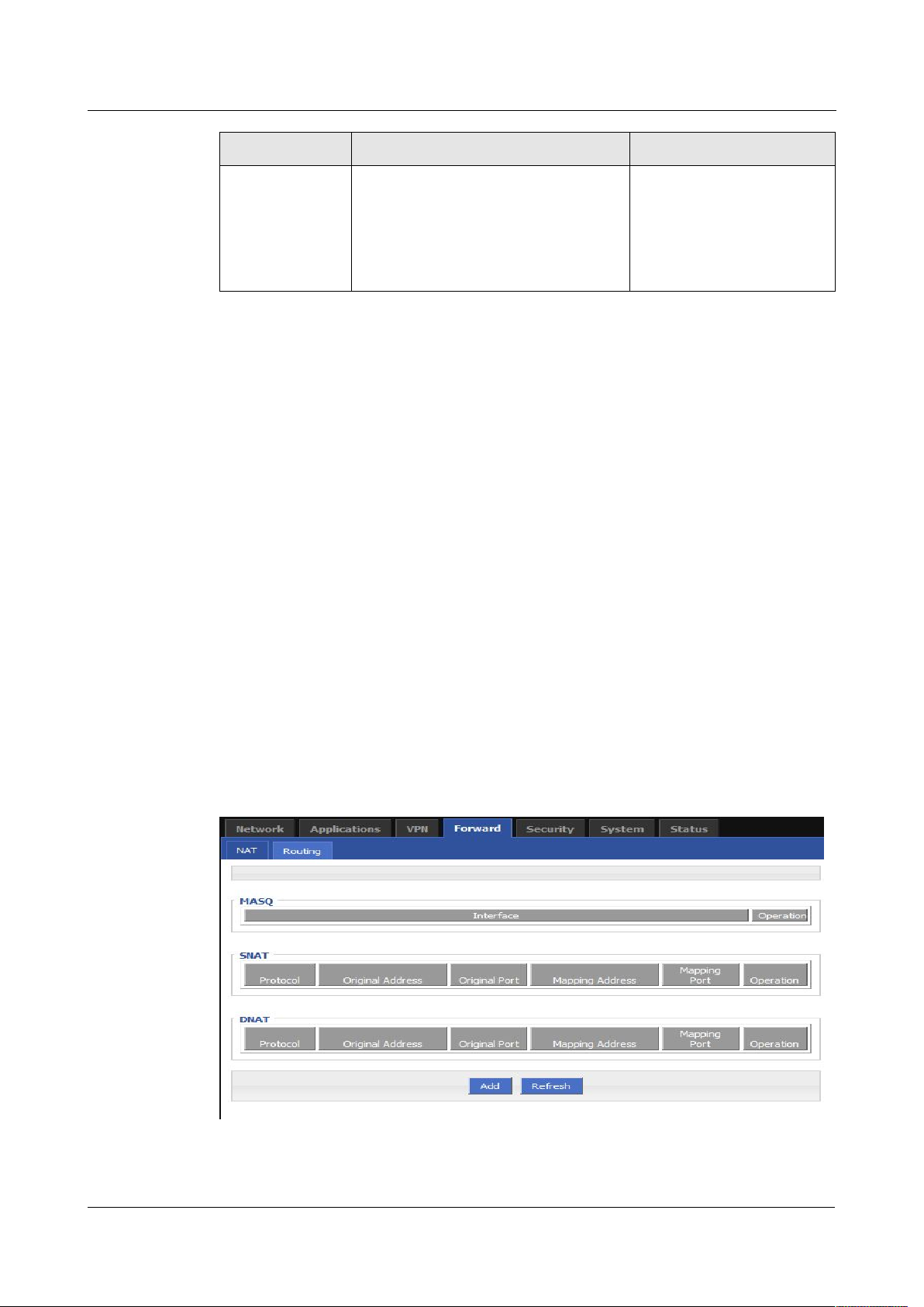
7 FAQ H792x 3G/4G Router
Input: all packages visiting router.
Forward: all packages forwarded by
Both: both Input and forward.
Step 6 Single click “save” icon to finish.
5.5 Forward configuration
5.5.2 Overview
5.5.3 NAT
Step 3 Log-on WEB GUI of H792x 3G/4G router.
Step 4 Click “Forward > NAT” to open “NAT” tab.
Figure 5-42 NAT tab
Parameter Details Operation
Filter mode To choose “Input”, “Forward” or
“Both”.
router.
---END
Forward function of H792x 3G/4G router includes NAT, Routing, dynamic routing (RIP,
OSPF) (optional) and QoS (optional).
To choose “Input”,
“Forward” or “Both”.
DNAT configuration rule
DNAT is used to replace the destination address of packets accessing external network, router
will replace the destination address of packet accessing external network into the user custom
settings.
38
7 -
(2014-05-28)
Page 73
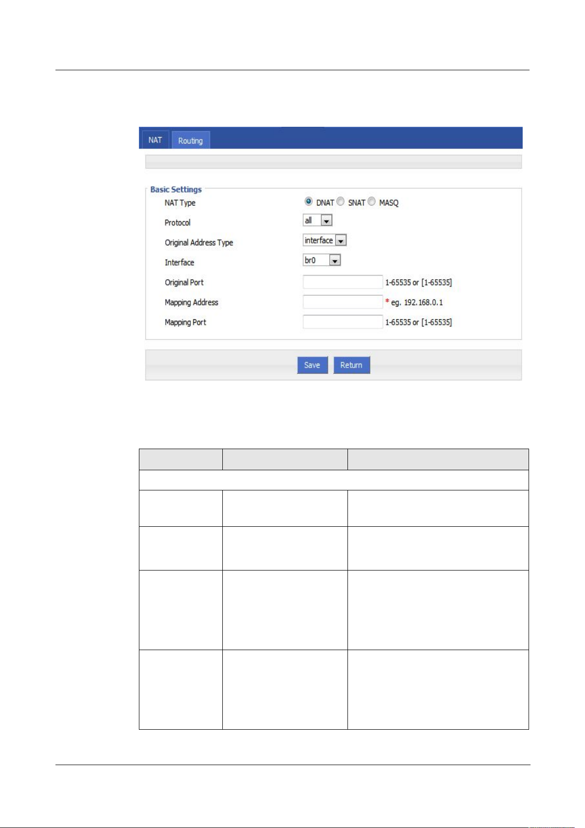
H92x 3G/4G Router 7 FAQ
Step 5 Click “Add” to add a new NAT rule.
Figure 5-43
DNAT rule configuration
Step 6 NAT Type select “DNAT”, Configure DNAT rule parameter.
Table 5-20 DNAT Parameter instruction
interface
static
br0
modem
modem2
eth0
eth1
Parameter Details Operation
Basic Settings
Protocol Supports “TCP”, “UDP”,
Select from Dropdown List
“ICMP” or “ALL”
Original Address
Type
The destination address of
the IP packet needs to be
Dropdown List
converted
Interface (when
the initial address
type select
Indicates the destination
address of IP packets to an
interface of the router
Dropdown List
“interface” ,
needs to be
configured)
Original Address
(when the initial
address type
select “static”,
The source address of IP
packet, the source
address needs to be
converted
Manual input
Format1:A.B.C.D
Format2: A.B.C.D/Mask
needs to be
configured)
Version (2014-05-28) 7 -
39
Page 74
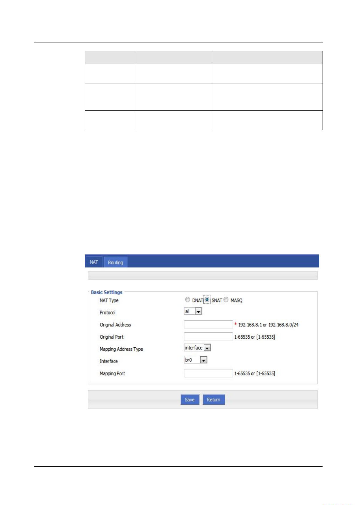
7 FAQ H792x 3G/4G Router
Step 7 Single click “save” icon to finish.
Step 3
Log-on WEB GUI of H792x 3G/4G router.
Step 4 Click “Forward > NAT” to open “NAT” tab.
Step 5 NAT Type select “SNAT”, Configuration interface as shown in Figure 5-47.
Figure 5-44
SNAT rule configuration
Step 6 Configure SNAT rule parameter,.
Parameter Details Operation
Original port The port of destination
Mapping address The new source address
Mapping port The port of destination
---END
SNAT configuration rule
SNAT is the source address translation, and its role is to translate source address of IP packets
into another address.
Value area: 1~65535
address need to be replaced
e.g. 192.168.8.1
after destination address is
replaced
Value area :1~65535
address after is replaced
7 -
40
Parameter instruction as Table 5-22
(2014-05-28)
Page 75

H92x 3G/4G Router 7 FAQ
Table 5-21 SNAT rule instruction
all
tcp
udp
icmp
interface
static
br0
modem
modem2
eth0
eth1
Step 7 Single click “save” icon to finish.
Step 3
Log-on WEB GUI of H792x 3G/4G router.
Step 4
Click “Forward > NAT” to open “NAT” tab.
Step 5
NAT Type select “MASQ”, Configuration interface as shown in Figure 5-48.
Parameter Details Operation
Protocol Convert some kind of protocol packets
Dropdown List
into address
Original Address The source address need to be replaced Manual input
Format1:A.B.C.D
Format2: A.B.C.D/Mask
Original Port The port of source address need to be
replaced
Value area: 1-65535 or
[1-65535], it can be a range,
or a single port
Mapping
Address Type
The new source address type after
source address is replaced
Interface Select the interface of the router as
Dropdown List
Dropdown List
source address after replacement
Mapping Port The port of source address after is
replaced
Value area: 1-65535 or
[1-65535], it can be a range,
or a single port
When SNAT rule is configured port, protocol select "all", said select "tcp", "udp" two protocols; when
SNAT rule is not configured port, protocol select "all", said select "tcp", "udp","icmp" three protocols.
---END
MASQ rule configuration
MASQ is MASQUREADE.
Version (2014-05-28) 7 -
41
Page 76
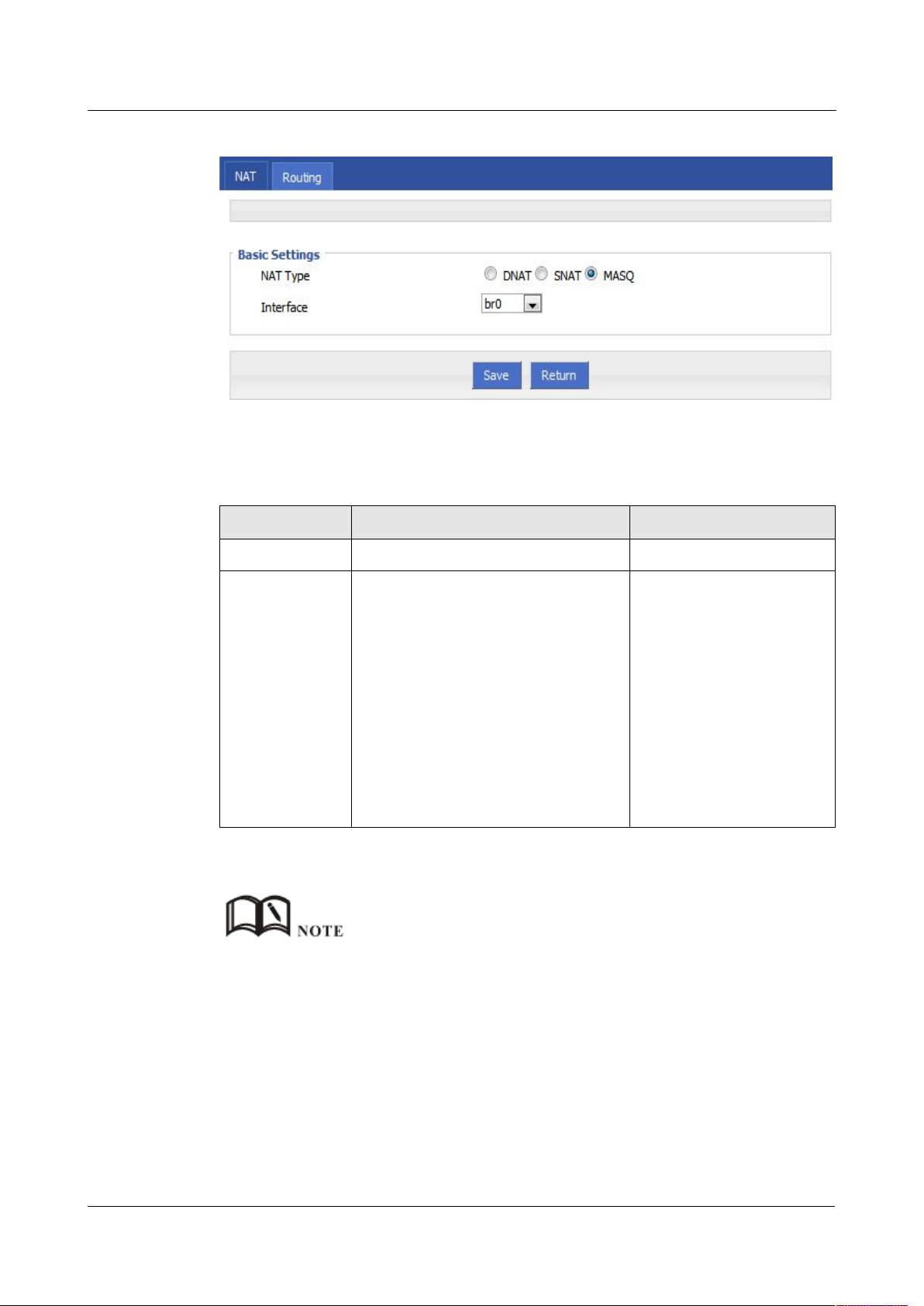
7 FAQ H792x 3G/4G Router
Figure 5-45 MASQ configuration
Step 6 Configure MASQ rule parameter.
Table 5-22 MASQ rule Parameter instruction
br0: use br0 interface as commutation
Modem: use modem interface as
modem2: use modem2 interface as
eth0: use eth0 interface as
Step 7 Single click “save” icon to finish.
5.5.4 Static Routing
Parameter Details Operation
NAT Type To select “MASQ” Select “MASQ”
Interface Interface includes:
Select from Dropdown List
address between router & LAN and
external network
commutation address between router
& LAN and external network
commutation address between router
& LAN and external network
commutation address between router
& LAN and external network
MASQ rule: the source address of all packets in the LAN need to be transferred into the specific ip
address of the router, so the PC from the LAN can send packets out; If MASQ rule in the router will be
deleted, the router LAN of the PC cannot communicate with external network.
---END
Static routing can forward packets according that the user configure specific forwarding path
manually. Static Routing form is divided into static routing and policy routing, static routing
is based on the destination address as an alternative route; while policy route is based on the
source address that match with the policy to forward the packets (forwarding router detects
42
7 -
(2014-05-28)
Page 77
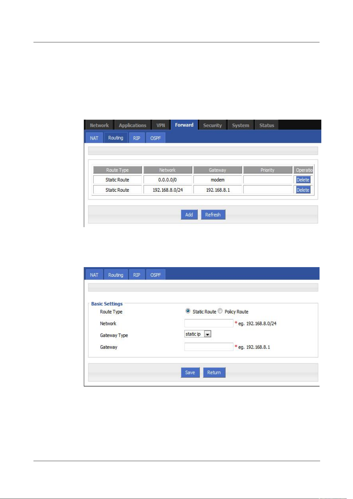
H92x 3G/4G Router 7 FAQ
Step 3
Log-on WEB GUI of H792x 3G/4G router.
Step 4
Click “Forward > Routing” to open “NAT” tab, as Figure 5-49.
Figure 5-46 Static Routing Interface
Step 5
Click “Add” to add a new static route, configure interface as Figure 5-50 and Figure 5-51.
Figure 5-47 Static Routing Interface
the received packet's source address, and then according to the source that match the
appropriate address of policy route to forward) and policy routing priority, use numbers 3 to
252 to differentiate, the smaller number with higher priority. And there are priorities between
static routing and policy routing: policy routing higher priority than static routing.
Version (2014-05-28) 7 -
43
Page 78
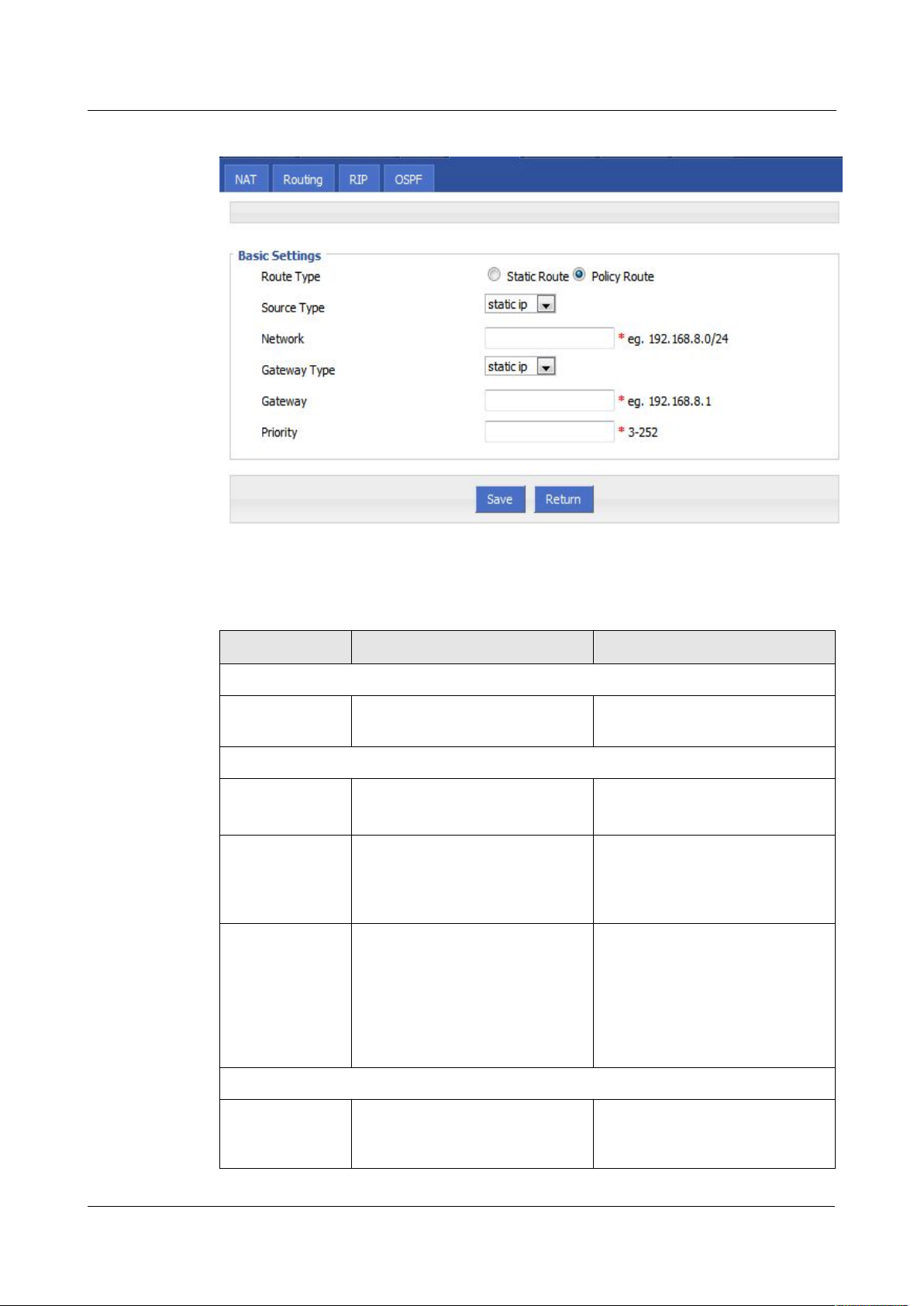
7 FAQ H792x 3G/4G Router
Figure 5-48 Policy Routing Interface
Table 5-23 Static Routing Parameter Instruction
interface
static ip
If the gateway type select static
If the gateway type select
Static IP
Interface
Parameter Instruction as Table 5-24.
Parameter Details Operation
Basic Setting
Routing Type To select “Static Route”or“Policy
Dropdown List
Route”
When Routing Type is “Static Route”
Network Set the destination IP address and
subnet mask of static route
Gateway Type Specify gateway type of static
Manual input
Format1: A.B.C.D/Mask
Dropdown List
routing, includes:
Gateway Set a next hop IP address of static
Dropdown List
route, IP address of the adjacent
router interface
IP, gateway need to manually
input, format: A.B.C.D
7 -
44
When Routing Type is “Policy Route”
Source Type Set source type of policy route
interface, the gateway needs to
select from dropdown list
Dropdown List
(2014-05-28)
Page 79

H92x 3G/4G Router 7 FAQ
modem
modem2
static ip
interface
Step 6 Single click “save” icon to finish the static routing setting.
5.5.5 QoS (Optional)
Step 3
Log-on WEB GUI of H792x 3G/4G router.
Step 4
Click “Forward > QoS” to open “QoS” tab, as Figure 5-52.
Parameter Details Operation
Network When source type is static route,
need to manually set network
address
Source Interface When source type is policy route,
need to manually set source
network address of policy router
Gateway Type Set the next hop IP of policy route
Gateway When the gateway type select
"Static IP" to fill in the IP address,
when gateway type is "interface",
it will use the selected interfaces
as gateway
Prority Set policy routing priority, the
priority lower the number, the
higher the priority
Manual input
Format1: A.B.C.D/Mask
Dropdown List
Dropdown List
Manual input
Format1: A.B.C.D/Mask
Value area:[3,252]
Static routing will select the route to forward according to the destination address of the packet receive
from the router, if the router received the packet (e.g. source address is 1.1.1.1 destination address is
2.2.2.2),
It will forward the packet to next hop according to the route which meets with the destination address
(2.2.2.2).
Policy routing will forward according to the source address of the packet, if the router received the
packet (e.g. source address is 1.1.1.1 destination address is 2.2.2.2), it will forward the packet to next
hop according to the route which meet with the source address (1.1.1.1).
Policy routing has higher priority than static routing, policy-based routing priority regardless of how
much.
---END
QoS (Quality of Service) quality of service, is a security mechanism for the network, is a
technique to solve the network bandwidth allocation and network priority and other issues.
When the network is overloaded or congested, QoS to ensure that critical traffic is not delayed
or dropped, while ensuring the efficient operation of the network, our H792x 3G/4G Router
supports custom QoS services.
Version (2014-05-28) 7 -
45
Page 80
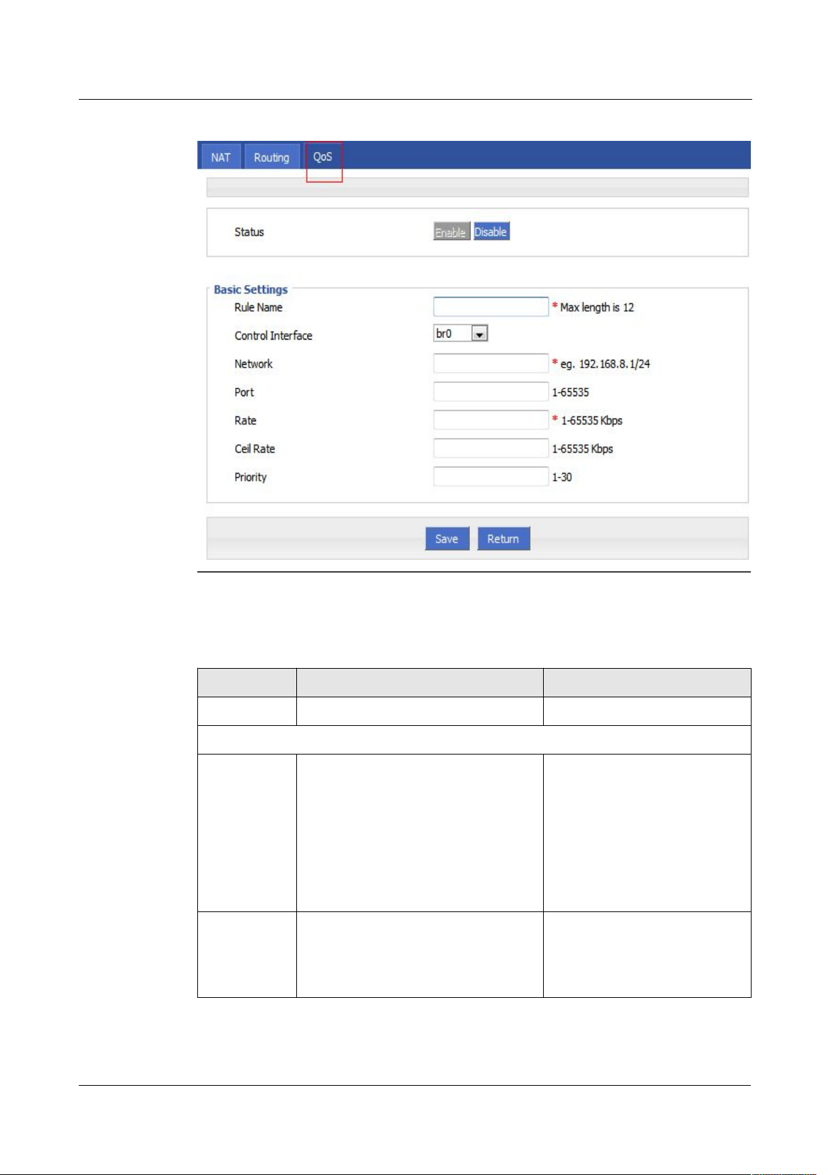
7 FAQ H792x 3G/4G Router
Figure 5-49 QoS interface
Step 5
QOS configuration parameter, configuration parameter instruction as Table 5-25.
Table 5-24 QoS parameter instruction
br0:QOS interface is LAN
modem:QOS interface is modem
modem2:QOS interface is modem2
Parameter Details Option
Status Enable or disable QoS feature Click the button to select
Basic Setting
Rule Name QoS rule name The max to 12 characters
Only set when adds a new rule
and the follow-up can not be
modified
The rule name can not be
repeated, otherwise the rule will
be covered after the rule is
added in front of the cover
Control
The interface type of QOS, include:
Dropdown List
Interface
7 -
46
(2014-05-28)
Page 81

H92x 3G/4G Router 7 FAQ
Step 6 Single click “save” icon to QOS setting.
5.5.6 Dynamic Routing (Optional)
Step 3
Log-on WEB GUI of H792x 3G/4G router.
Step 4
Click “Forward > RIP” to open “RIP” tab, as Figure 5-53.
Parameter Details Option
Network The network address that flow into or
out QOS, the limited speed of object
Full in destination address and
subnet mask
Manual input
Format1: A.B.C.D/Mask
Port The network interface of QOS Value area: 1-65535
You can not configure the port,
if not the configuration
represents all ports
Rate Transmission rate of the network
address settings
Ceil Rate In ensuring the basic rate and the spare
bandwidth, the maximum bandwidth of
the network address of the
Value area:1~65535
Units:Kbps
Value area:1~65535
Units:Kbps
communication can be obtained with
higher priority will be given priority
redundant bandwidth
Priority Set the precedence of the rules
Value area:[1,30]
QOS is mainly for the average of user priority assigned route or a bandwidth of Internet users. If the router is
connected with two subnets: 192.168.8.1/24 and 192.168.9.1/24, the router QOS can control the rate of these
two subnets; If the router's bandwidth is relatively well-off, the router can be based on two subnets redundant
bandwidth is first priority and high priority redundancy to meet the bandwidth, then meet low priority subnet
redundancy bandwidth.
---END
RIP configuration
RIP protocol (Routing Information Protocol) is the most widely IGP (Interior Gateway
Protocol) , it was designed for the same technology used in small networks, and therefore
adapt to most of the campus network and used in a continuous regional networks that the rate
change is not big, H792x 3G/4G Router supports RIP v2 protocol. For more complex
environments, generally do not use the RIP protocol.
Version (2014-05-28) 7 -
47
Page 82
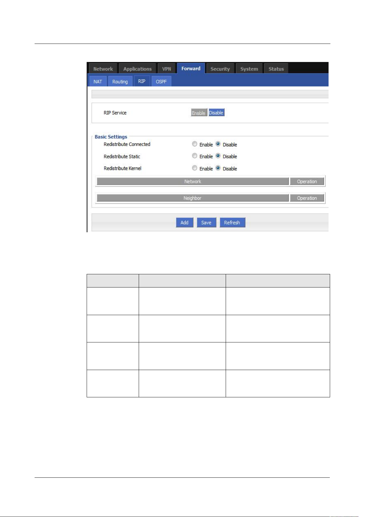
7 FAQ H792x 3G/4G Router
Figure 5-50 RIP interface
Table 5-25 RIP Parameter Instruction
Enable
Disable
Enable
Disable
Enable
Disable
Enable
Disable
Step 5 Click “Add” to add a new RIP route, configuration interface as Figure 5-54.
Parameter Instruction as Table 5-26.
Parameter Details Operation
RIP Service Enable or disable RIP Service Click the button to select.
Redistribute
Connected
Redistribute
Static
Redistribute
Kernel
Enable or disable Redistribute
Connected
Enable or disable Redistribute
Static
Enable or disable Redistribute
Kernel
Click the button to select.
Click the button to select.
Click the button to select.
7 -
48
(2014-05-28)
Page 83
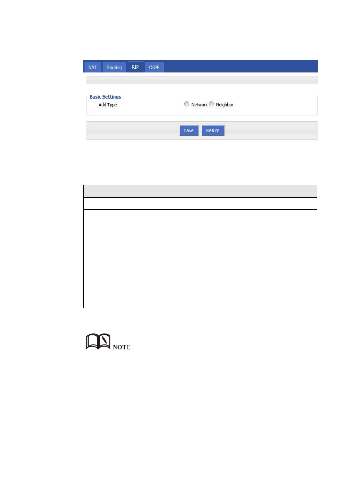
H92x 3G/4G Router 7 FAQ
Figure 5-51 RIP route configuration interface
Step 6
Configure RIP route parameter instruction, as Table 5-27.
Table 5-26 RIP parameter instruction
When it is “Network”, need to
When it is “Neighbor”, need to
Step 7
Single click “save” icon to RIP route setting.
Parameter Details Operation
Basic Setting
Add Type Add the type of RIP route Click the button to select Add Type
configure destination network address.
configure neighbor’s IP address
Network(directly
connect to the
router)
Neighbor(directly
connect to the
router)
RIP is an interior gateway protocol. In the national networks ( such as the current Internet ) , has a lot for
the entire network routing protocols. Only adjacent routers exchange information. If the communication
between the two routers do not go through another router , the two routers are adjacent. RIP agreement,
without the exchange of information between non-adjacent routers.
Routers exchanging information is all the information currently known to the router . That is its own
routing table. At a fixed time to exchange routing information ( such as every 30 seconds ) , then the
router receives the routing information to update the routing table.
RIP protocol "distance" also known as " hops " (hop count), because each through a router hop count is
incremented . RIP is considered a good route it through a small number of routers , namely, " a short
distance ." RIP allows a path can contain up to 15 routers. Therefore, the "distance" equal to 16 hop
which is equivalent unreachable. RIP visible only for small Internet.
Add the destination
network of RIP route
Add the neighbor’s IP
address of RIP route
Add the destination network of RIP
route
Format: A.B.C.D/Mask
Add the neighbor’s IP address of RIP
route
Format: A.B.C.D
---END
Version (2014-05-28) 7 -
49
Page 84
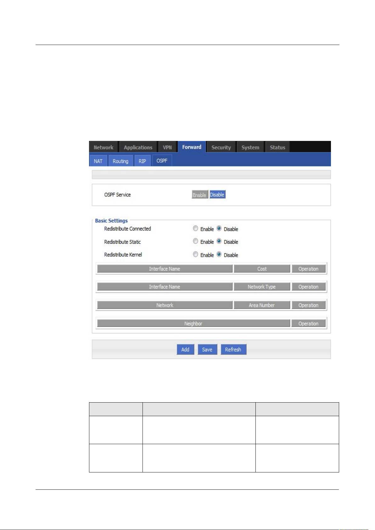
7 FAQ H792x 3G/4G Router
Step 3
Log-on WEB GUI of H792x 3G/4G router.
Step 4 Click “Forward > OSPF” to open “OSPF” tab, as Figure 5-55.
Figure 5-52
OSPF Interface
Table 5-27 OSPF parameter instruction
Enable
Disable
Enable
Disable
OSPF configuration
OSPF (Open Shortest Path First) protocol is one of the (Interior Gateway Protocol), the most
widely used IGP, for a single AS (autonomous system) in the routing decisions for large
networks. OSPF business can be based whether the user needs to be configured at the factory
H792x 3G/4G Router.
7 -
50
OSPF parameter instruction as Table 5-28
Parameter Details Operation
OSPF Service Enable or disable OSPF Service Click the button to select
Redistribute
Connected
Enable or disable Redistribute
Connected
Click the button to select
(2014-05-28)
Page 85
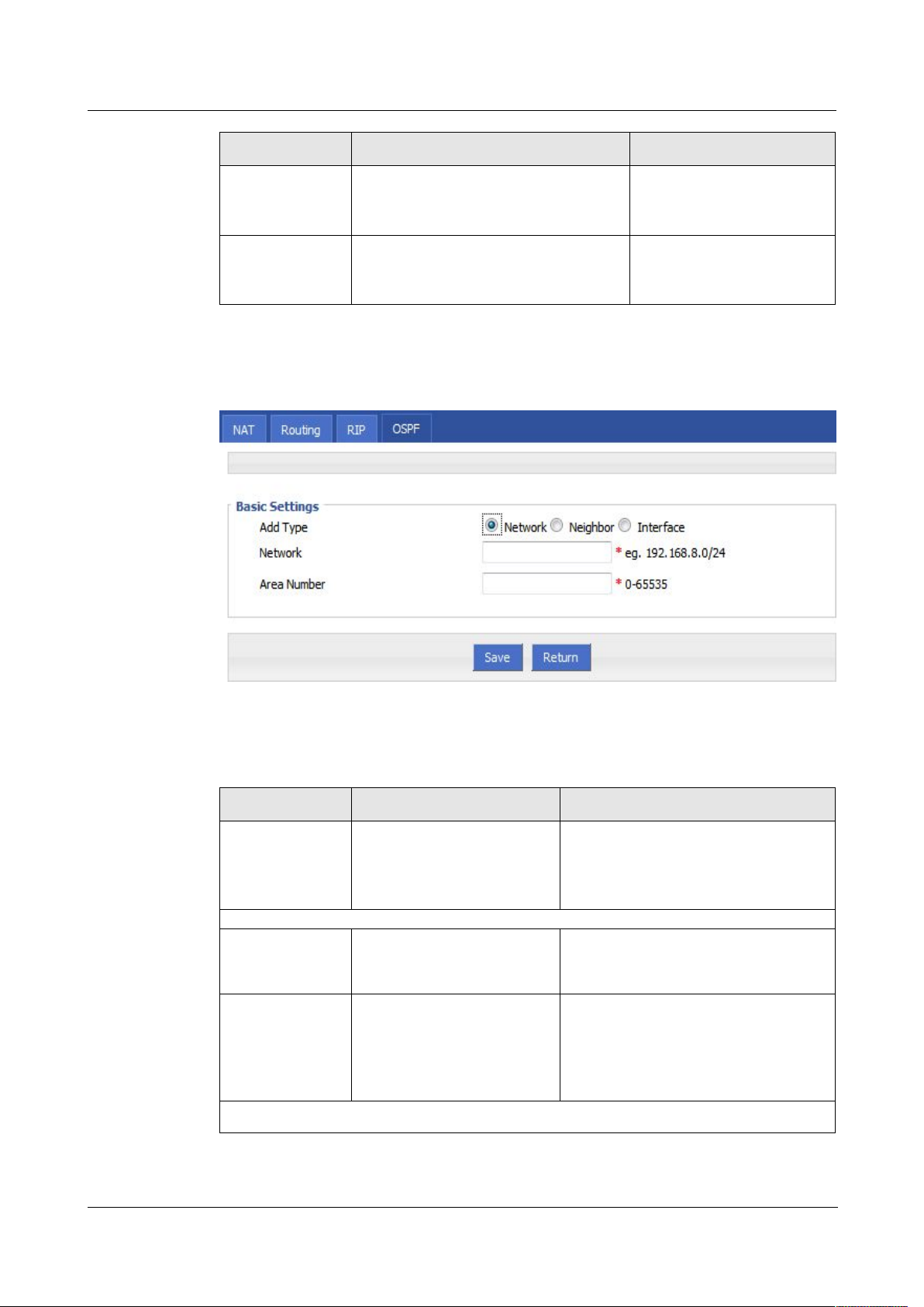
H92x 3G/4G Router 7 FAQ
Enable
Disable
Enable
Disable
Step 5 Click “Add” to add a new OSPF route, configuration interface as Figure 5-56.
Figure 5-53 OSPF route configuration interface
Step 6 Configure RIP route parameter instruction, as Table 5-29.
Table 5-28 OSPF route parameter instruction
Parameter Details Option
Add Type Add the type of OSPF route Click the button to select Add Type
Network
Neighbor
Interface
When Add Type is “Network”,
Network Set the network address as
ospf sending address
Manual input
Format1: A.B.C.D/Mask
AS Number Used to identify the network
(only the routers with the
same domain address can
exchange routing
information)
Manual input
Value area:[0,65535]
When Add Type is “Neighbor”,
Parameter Details Operation
Redistribute
Static
Redistribute
Kernel
Enable or disable Redistribute Static Click the button to select
Enable or disable Redistribute Kernel Click the button to select
Version (2014-05-28) 7 -
51
Page 86

7 FAQ H792x 3G/4G Router
Step 7
Single click “save” icon to OSPF route setting.
Step 8
Single click “save” icon to finish.
5.6 VPN configuration (H7921 only)
5.6.2 Overview
Neighbor The router can reach in the
next hop
Manual input
Format1: A.B.C.D/Mask
When Add Type is “Interface”,
Interface Name The interface of the router
Dropdown List
br0
modem
modem2
eth1
eth0
Interface
Attribute
Configure the router
interface attribute, include
cost and network
Click the button to select
cost
network
Cost Configure the cost of the
router interface, used to learn
routing table
Manual input
Value area:1-65535
Network type
(when the
interface
attribute is
network)
Configure the network type
of the router interface
Dropdown List
broadcast
non-broad
point-to-multipoint
point-to-point
OSPF is a link-state (Link-state) routing protocol, commonly used for the same routing domain. Here,
the routing domain is an autonomous system, which refers to the routers can switch routing information
through a unified network switching or routing protocol routing policy in the AS, all OSPF routers
maintains an identical description of the database structure AS, which is stored in the database link status
information corresponding routing domain, OSPF router is through this database to calculate its OSPF
routing table.
As a link-state routing protocol, OSPF link state broadcast data LSA (Link State Advertisement) sent to
all routers in an area, which is different from the distance vector routing protocols. Distance vector
routing protocol passed some or all routing information of the routing table to the adjacent routers.
---END
H792x 3G/4G router supports VPN (Virtual Private Network) including
L2TP/PPTP/GRE/IPIP/IPSEC. What’s more, it supports VPN OVER VPN, e.g. GRE over
IPSec, IPSec over PPTP/L2TP/GRE/IPIP.
7 -
52
(2014-05-28)
Page 87
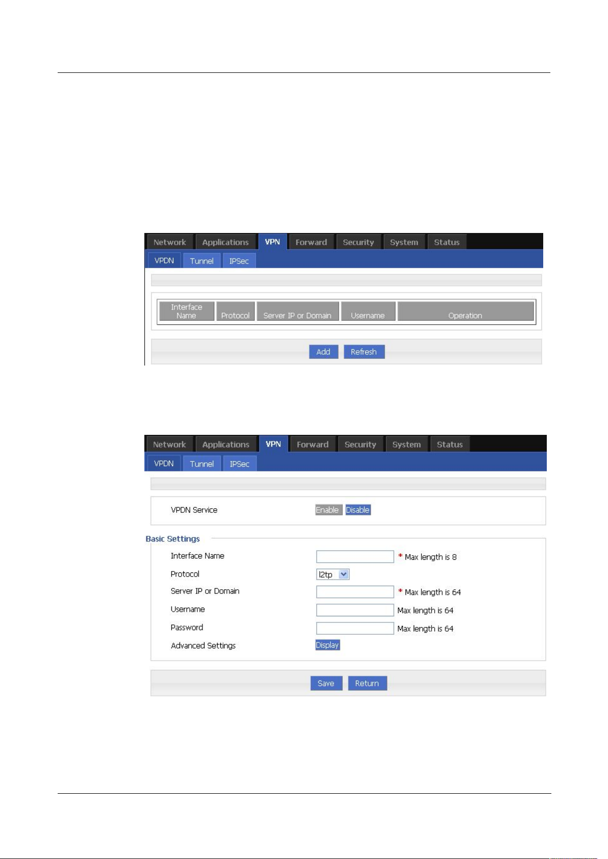
H92x 3G/4G Router 7 FAQ
5.6.3 VPDN configuration
Step 3 Log-on WEB GUI of H792x 3G/4G router.
Step 4 Click “VPN > VPDN” to open “VPDN” tab.
Figure 5-54 VPDN configuration
Step 5 Click “Add” to add a new VPDN rule.
Figure 5-55 VPDN rule configuration
Step 6
Configure VPDN rule parameter.
VPDN stands for Virtual Private Dial-up Networks. Now VPDN supports L2TP and PPTP
See “4.2.1 Login WEB GUI
Version (2014-05-28) 7 -
53
Page 88
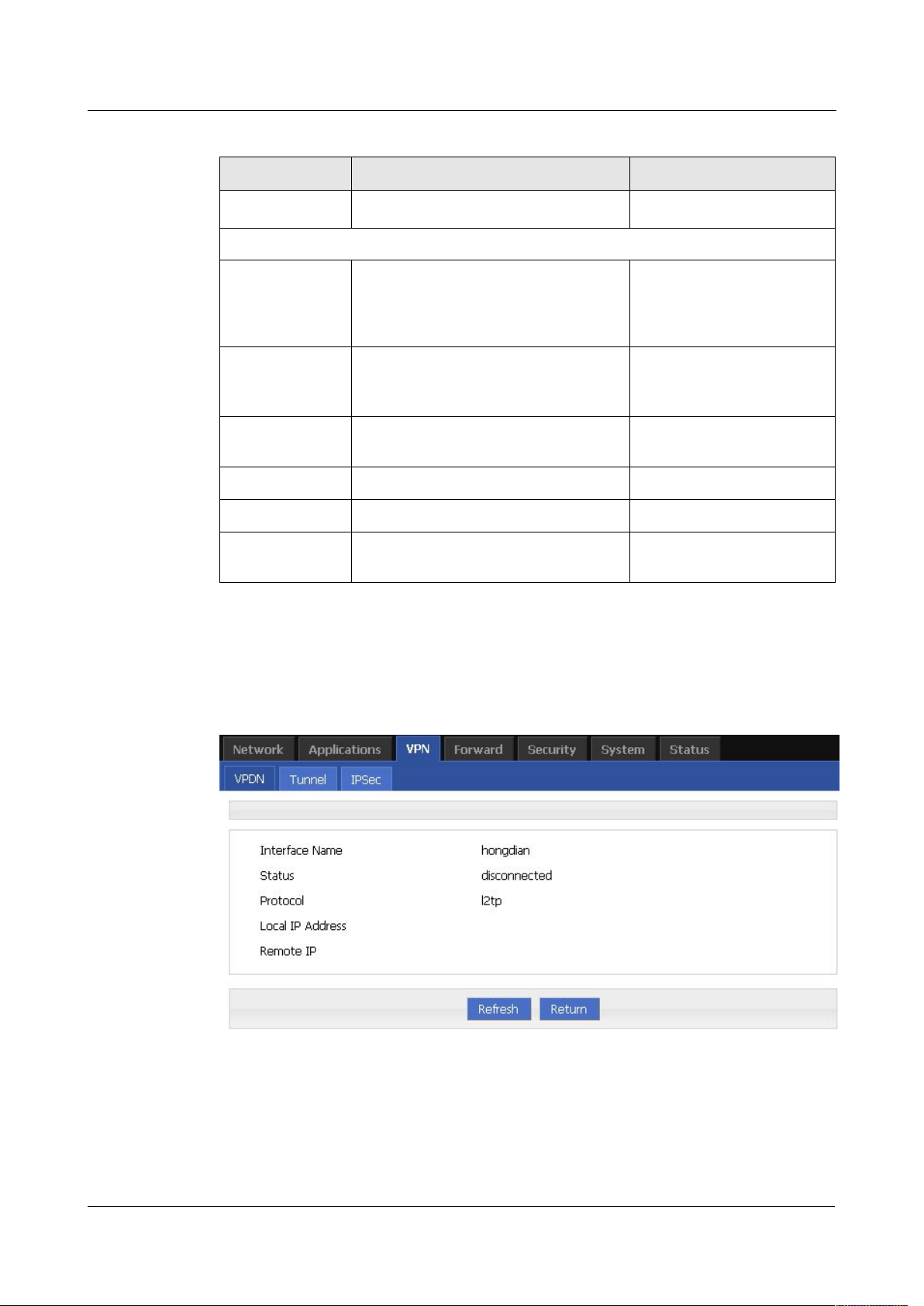
7 FAQ H792x 3G/4G Router
Table 5-29 VPDN rule parameter instruction
L2TP
PPTP
Step 7
Single click “save” icon to finish.
Figure 5-56 L2TP tunnel status
Parameter Details Operation
VPDN service To enable or disable the VPDN rule Click “Enable”
Basic Settings
Interface name Name of this VPDN rule Cannot be modified after
save.
protocol VPDN protocol includes
Select from Dropdown List,
cannot be modified after
save.
Service IP or
Domain
IP or domain of server to be visited To input the IP or domain of
server to be visited.
Username Username of server to be visited To input the username.
Password Password of server to be visited To input password.
Advanced
Advanced parameter of PPP link Click “Display”
settings
After a VPDN rule is added, router will build VPN communication with service address
automatically. To see the tunnel status, click “View” in “Tunnel” tab.
7 -
54
---END
(2014-05-28)
Page 89
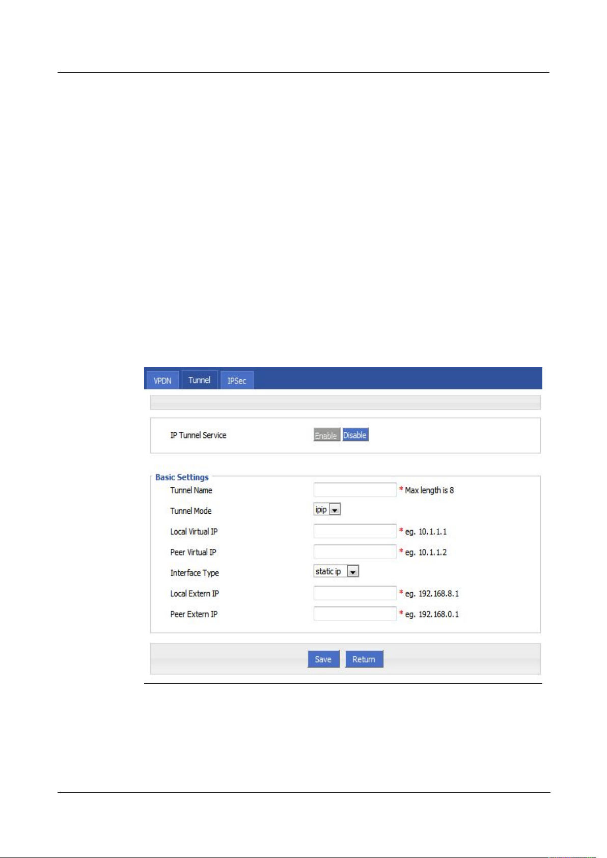
H92x 3G/4G Router 7 FAQ
5.6.4 Tunnel configuration
Step 3 Log-on WEB GUI of H792x 3G/4G router.
Step 4 Click “VPN > Tunnel” to open “Tunnel” tab.
Step 5 Click “Add” to add a new tunnel.
Figure 5-57 Tunnel configuration
Step 6
Configure Tunnel rule parameter
Tunneling through a network infrastructure to transfer data between the network mode. The
entire transfer process, the logic path encapsulated packet delivery over the public Internet
through which called tunnel.
GRE and IPIP Tunnel configuration supports two modes.
GRE (Generic Routing Encapsulation, Generic Routing protocol encapsulation) specifies how
to use a network protocol to another network protocol encapsulation method. The main
purpose of the GRE protocol, there are two: internal protocol encapsulation and private
address encapsulation.
IPIP tunnel is a simple agreement between two routers for IP packet encapsulation, IPIP
tunnel interface will be like a physical interface in the interface list, many routers including
Cisco, basically support the agreement. This agreement enables multiple network distribution
possible.
Version (2014-05-28) 7 -
55
Page 90

7 FAQ H792x 3G/4G Router
Table 5-30 Tunnel rule parameter instruction
gre
ipip
Step 7 Single click “save” icon to finish.
5.6.5 IPSec configuration
Step 3 Log-on WEB GUI of H792x 3G/4G router.
Step 4 Click “VPN > IPSec” to open “IPSec” tab.
Parameter Details Operation
IP Tunnel
Service
To enable or disable IP tunnel
service
Click “Enable”
Basic Settings
Tunnel name Name of the tunnel, cannot be
Input the name of tunnel
modified after save
Tunnel Mode Tunnel mode:
Select from Dropdown List
Local virtual IP Virtual IP address of local tunnel Format: interface type
A.B.C.D/M.
Peer virtual IP Virtual IP address of peer tunnel Format: interface type
A.B.C.D/M.
Interface type To choose “interface” or “static IP” Select from Dropdown List.
Local Extern
interface
This parameter will need to be set if
“interface” is selected in “interface
Select from Dropdown List.
type”. Choose any connected
interface as external interface
Local extern IP This parameter need to be set if
“static IP” is selected for “interface
Format: interface type
A.B.C.D/M.
type”. It is to set IP address to
external network
Peer extern IP External interface IP of counterpart
network tunnel. Usually a public IP
address, also can be a LAN IP
---END
Format: interface type
A.B.C.D/M.
56
7 -
(2014-05-28)
Page 91
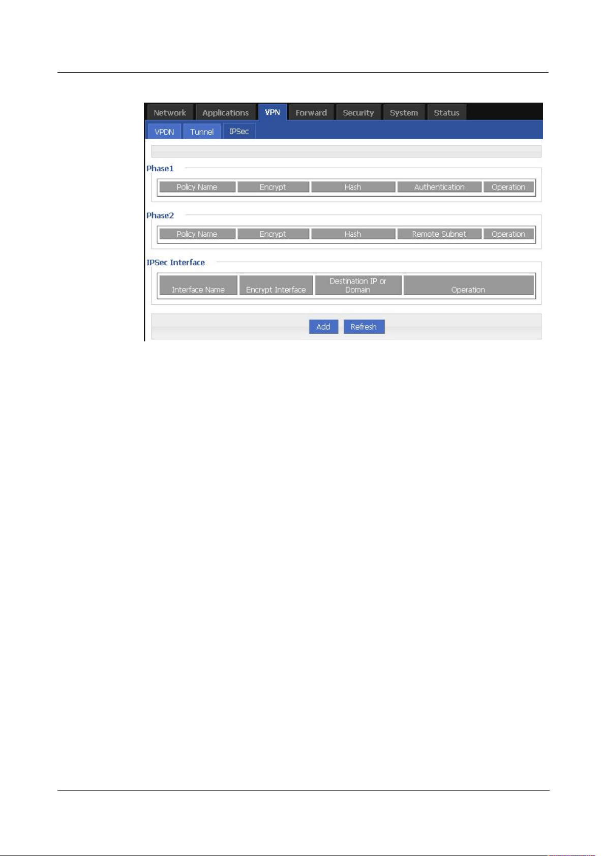
H92x 3G/4G Router 7 FAQ
Figure 5-58 IPSec tab
Step 5
Click “Add” to add a new IPSec rule.
1.
Phase 1 parameter
There are 3 phases for IPSec configuration:
Version (2014-05-28) 7 -
57
Page 92
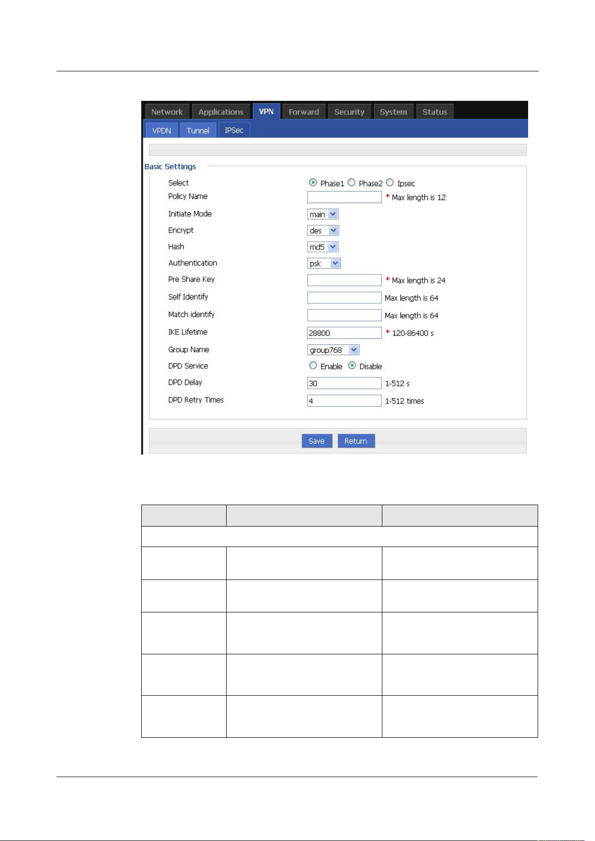
7 FAQ H792x 3G/4G Router
Figure 5-59 IPSec phase 1 configuration
Table 5-31 IPSec Phase 1 Parameter instruction
7 -
58
Parameter Details Operation
Basic Settings
Select To select which phase of IPSec,
Select “Phase 1”
phase 1, phase 1 or phase IPSec
Policy Name Name of phase 1, mainly to match
phase “IPSec”
To input the name of phase 1.
Cannot be changed after save.
Initial Mode To choose “main” or “aggr” Select from Dropdown List,
“aggr” is recommended
Encrypt Supports 3des and aes Select from Dropdown List
Hash Supports md5 and sha1 Select from Dropdown List
(2014-05-28)
Page 93

H92x 3G/4G Router 7 FAQ
2.
Phase 2 parameter.
Parameter Details Operation
Authentication To select authentication Select from Dropdown List,
presently only “PSK” supported
Pre Share Key To set pre share key Max 24 letters
Self Identify To set the self ID of IPSec To input the ID, need to match the
ID of other side
Match Identify To input the match ID of IPSec To input match ID, need to match
ID of other side
IKE Lifetime Life time of IKE key
Value area: 120~86400
Unit: second
Group Name Select group Select from Dropdown List
DPD Service To enable DPD service To click “Enable”
DPD Delay To set DPD check interval time Manual input
Value area : 1~512
Unit: second
DPD Retry
Times
Single click “save” icon to finish phase 1 configuration.
Max times to continuous DPD
check failure.
Manual input
Value area: 1~512
In above parameters, “Initial Mode”, “Encrypt”, “Hash”, “Authentication” “Pre Share Key”,
“IKE Lifetime”, “Group Name” need to match parameter of IPSec server. “Self Identify” and
“Match Identify” needs to match “match Identify” and “Self Identify” of IPSec sever
respectively.
Version (2014-05-28) 7 -
59
Page 94
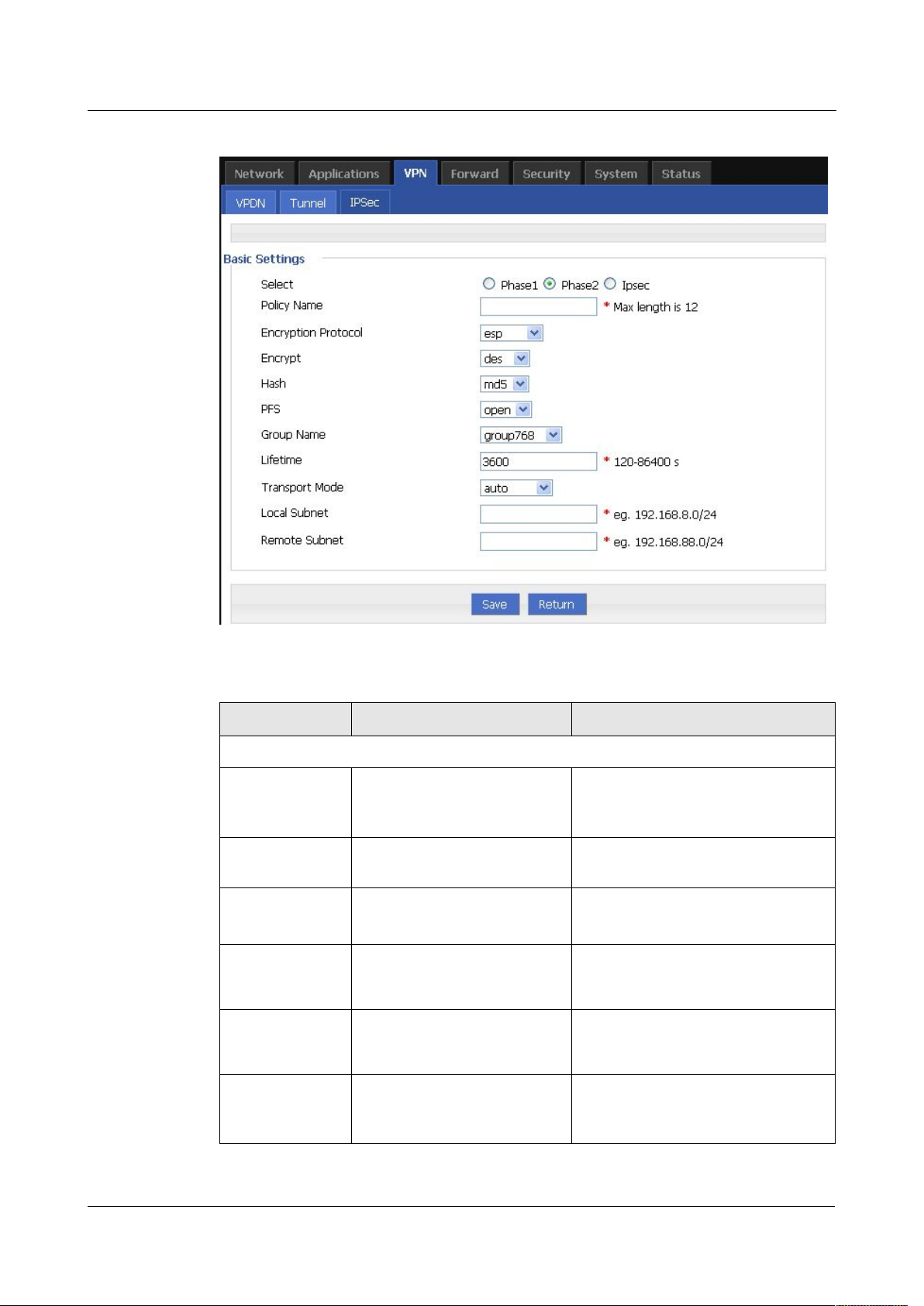
7 FAQ H792x 3G/4G Router
Figure 5-60 IPSec phase 2 configuration
Table 5-32 IPSec Parameter instruction
Parameter Details Operation
Basic Settings
Select To select which phase of
Select “Phase 2”
IPSec, phase 1, phase 1 or
phase IPSec
Policy Name Name of phase 2, mainly to
match phase “IPSec”
Encryption
Supports esp, ah, ah+esp Select from Dropdown List
To input the name of phase 2. Cannot
be changed after save
Protocol
Encryption Supports des, 3des, aes Select from Dropdown List
Hash Supports md5 and sha1 Select from Dropdown List
Group Name Need to configured when PFS
Select from Dropdown List
is “open”, to set the key length
of SA initial of phase 2
7 -
60
(2014-05-28)
Page 95
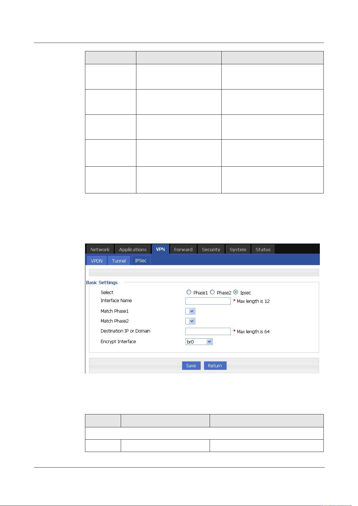
H92x 3G/4G Router 7 FAQ
3. “IPSec” parameter configuration
Figure 5-61 IPSec configuration tab
Table 5-33 IPSec Parameter instruction
Parameter Details Operation
PFS To open or close PFS Select from Dropdown List
Lifetime IPSec SA key life time
Value area: 120~86400
Unit: second
Transport Mode Supports tunnel, transport and
Select from Dropdown List
auto.
Local Subnet Set local subnet No need to set for “transport”
mode,only for “auto” and “tunnel”.
Format: A.B.C.D/M
Remote Subnet To set local subnet No need to set for “transport”
mode,only for “auto” and “tunnel”.
Format: A.B.C.D/M
Single click “save” icon to finish phase 2 setting.
To configure “IPSec” parameter, and then click “Save”.
Parameter Details Operation
Basic Settings
Select To select which phase of IPSec, Select “IPSec”
Version (2014-05-28) 7 -
61
Page 96

7 FAQ H792x 3G/4G Router
5.7 System configuration
5.7.2 Overview
5.7.3 Local Log
Step 3 Log-on WEB GUI of H792x 3G/4G router.
Step 4 Click “System > Local Log” to open “Local Log” tab.
Parameter Details Operation
phase 1, phase 1 or phase IPSec
Interface
Name
Match
Phase1
Match
Phase2
Destination
IP or
Domain
Encryption
Interface
Name of this phase Input name
To select a matching name of
“phase1”
To select a matching name of
“phase2”
counterpart IPSec server IP or
domain
To select binding interface of
IPSec. to bind
VPDN/modem/br0 as local
interface of IPSec initial can
support IPSec OVER VPDN. In
addition, after binding, IPSec
rule will change as per the
charge of binded interface. Thus
can resume link of IPSec dialing
interface and keep IPSec linked
as soon as possible
Select from Dropdown List.
Select from Dropdown List
Input counterpart IPSec server IP or
domain
Select from Dropdown List
---END
“System” can let you know the status of router, firmware upgrading and other maintenance.
62
7 -
(2014-05-28)
Page 97

H92x 3G/4G Router 7 FAQ
Figure 5-62 Local Log tab
Step 5
Select type of “Local Log” and then click “View” to see log.
Message: system log, to record the running log of router, usually for most of users.
Application: application program log, to record the Open or close of some application
Kernel: kernel log of router, usually for R&D engineers.
5.7.4 Remote Log
Step 3 Log-on WEB GUI of H792x 3G/4G router.
Step 4 Click “System > Remote Log” to open “Local Log” tab.
Click “Clear” to clear the log info in the “Log Table”, and click “Export” to export log in your
local PC.
There are 3 types log:
programs.
To see “local log”, “remote log” must be enabled.
---END
Version (2014-05-28) 7 -
63
Page 98
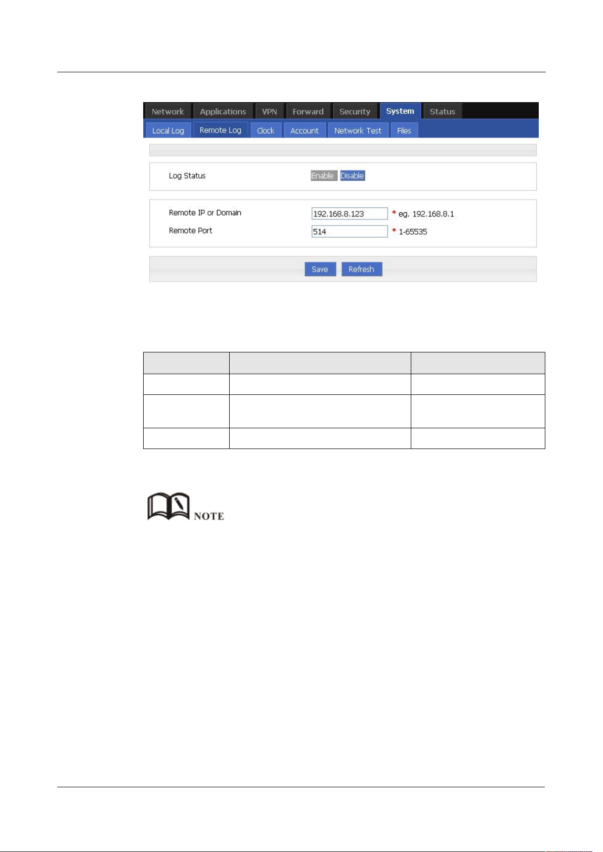
7 FAQ H792x 3G/4G Router
Figure 5-63 Remote Log tab
Step 5 Configure “Remote Log” parameter.
Table 5-34 Remote log parameter instruction
Step 6
Single click “save” icon to finish “Remote Log” parameter configuration.
5.7.5 Clock
Step 3 Log-on WEB GUI of H792x 3G/4G router.
Step 4
Click “System > Clock” to open “Clock” tab.
Parameter Details Operation
Log Status To enable or disable remote log Click “Enable”
Remote IP or
Domain
Remote Port Port of remote log serve Default port: 514
A software tool Syslog is use to receive remote log in server. Syslog can be downloaded at website of
Hongdian www.hongdian.com.
---END
IP address or Domain of remote log
server
To input the IP address or
domain to receive log
64
7 -
(2014-05-28)
Page 99
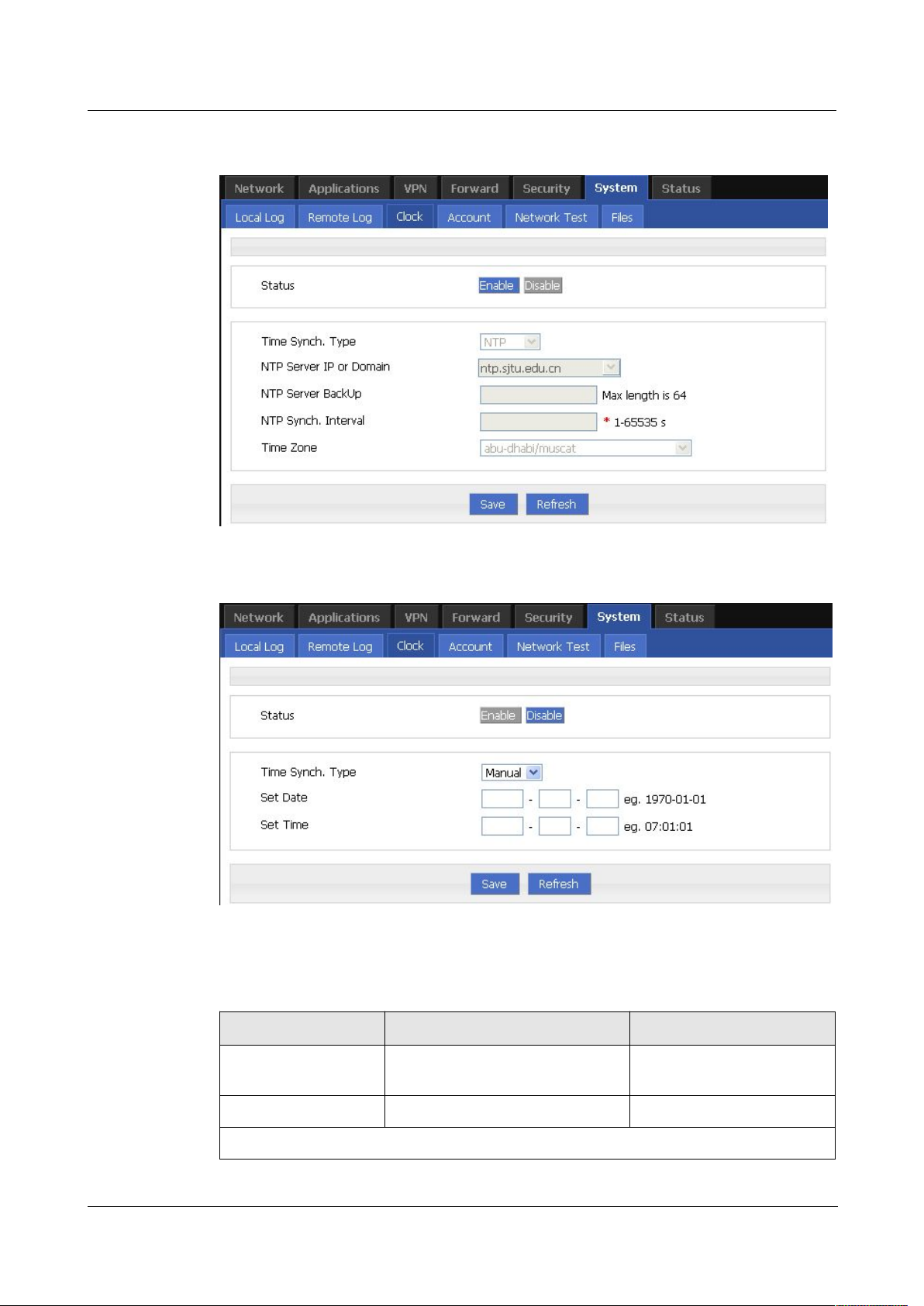
H92x 3G/4G Router 7 FAQ
Figure 5-64 “NTP” Time Synch.
Figure 5-65
Manual Time Synch. Type
Step 5 Set “clock” parameter .
Table 5-35 Clock Parameter instruction
Parameter Details Operation
Status To enable to disable Time
Synchronization service
Time Synch. Type Type to synchronize system time
To click “Enable” or
“Disable”
Select “NTP” or “Manual”
When select “NTP” in “Time Synch. Type”
Version (2014-05-28) 7 -
65
Page 100

7 FAQ H792x 3G/4G Router
Step 6 Single click “save” icon to finish.
5.7.6 Account
Step 3 Log-on WEB GUI of H792x 3G/4G router.
Step 4 Click “System > Account” to open “Account” tab.
NTP Server IP or
Domain
NTP Server Backup Backup NTP server Manual input server domain
NTP Synch. Interval Interval of NTP to check time with
Time Zone Time Zone Select from Dropdown List
Time Zone Number For “Custom” option in “Time
When select “Manual” in “Time Synch. Type”
Set Date To set date YYYY-MM-DD
Set Time To set time HH:MM:mm
IP or domain of NTP server Select from Dropdown List
or IP address
Value area: 1~65535
Server. E.g every 10 minutes
Zone”. E.g +8 or -4
Unit: second
Default: 600 s
WORD type
e.g 1970-01-01
Eg. 07:01:01
---END
“Account” is to change username/password, change web port and forbid other users to
visiting the router.
66
7 -
(2014-05-28)
 Loading...