

Honeywell Analytics Asia Pacific TPPLW Users manual

Technical Handbook
Touchpoint Plus Wireless
i

Revision
Comment
Date
1.0.0.0
initial draft
25/07/2018
Revision History
ii

Disclaimer
In no event shall Honeywell be liable for any damages or injury of any nature or kind, no matter how caused,
that arise from the use of the equipment referred to in this manual.
Strict compliance with the safety procedures set out and referred to in this manual, and extreme care in the
use of the equipment, are essential to avoid or minimise the chance of personal injury or damage to the
equipment.
The information, figures, illustrations, tables, specifications, and schematics contained in this manual are
believed to be correct and accurate as at the date of publication or revision. However, no representation or
warranty with respect to such correctness or accuracy is given or implied and Honeywell will not, under any
circumstances, be liable to any person or corporation for any loss or damages incurred in connection with the
use of this manual.
The information, figures, illustrations, tables, specifications, and schematics contained in this manual are
subject to change without notice.
Unauthorised modifications to the gas detection system or its installation are not permitted, as these may give
rise to unacceptable health and safety hazards.
Any software forming part of this equipment should be used only for the purposes for which Honeywell
supplied it. The user shall undertake no changes, modifications, conversions, translations into another
computer language, or copies (except for a necessary backup copy).
In no event shall Honeywell be liable for any equipment malfunction or damages whatsoever, including
(without limitation) incidental, direct, indirect, special, and consequential damages, damages for loss of
business profits, business interruption, loss of business information, or other pecuniary loss, resulting from
any violation of the above prohibitions.
Warranty
Honeywell Analytics warrants the Touchpoint Plus system against defective parts and workmanship, and will
repair or (at its discretion) replace any components that are or may become defective under proper usage
within 12 months from the date of commissioning by a Honeywell Analytics approved representative* or 18
months from shipment from Honeywell Analytics, whichever is sooner.
This warranty does not cover consumable, batteries, fuses, normal wear and tear, or damage caused by
accident, abuse, improper installation, unauthorized use, modification or repair, ambient environment,
poisons, contaminants or abnormal operating conditions.
This warranty does not apply to sensors or components that are covered under separate warranties, or to any
3rd-party cables and components
Any claim under the Honeywell Analytics Product Warranty must be made within the warranty period and as
soon as reasonably practicable after a defect is discovered. Please contact your local Honeywell Analytics
Service representative to register your claim.
This is a summary. For full warranty terms please refer to the Honeywell Analytics’ General Statement of
Limited Product Warranty, which is available on request.
* A Honeywell Analytics approved representative is a qualified person trained or employed by Honeywell
Analytics, or a qualified person trained in accordance with this manual.
Copyright Notice
Microsoft, MS and MS–DOS are registered trademarks of Microsoft Corp.
Other brand and product names mentioned in this manual may be trademarks or registered trademarks of
their respective companies and are the sole property of their respective holders.
Honeywell is the registered trademark of Honeywell Automation and Control Systems (ACS).
Touchpoint is a registered trademark of Honeywell Analytics.
Find out more at www.honeywellanalytics.com
iii

3020M5001_Iss 1_07/18 Touchpoint Plus Wireless
Technical Handbook
Contents
Chapter 1 – Important Safety Information ............................................................................ 1
1.1 Cautions ..................................................................................................................................... 3
1.1.1 Intended Readers .............................................................................................................. 3
1.1.2 Conventions Used ............................................................................................................. 4
1.1.3 Associated Manuals .......................................................................................................... 4
Chapter 2 – Safety Hazards, Warnings and Cautions ......................................................... 5
2.1 Safety ......................................................................................................................................... 5
2.1.1 Warnings and Cautions ..................................................................................................... 5
2.1.2 Safety Hazards .................................................................................................................. 6
2.2 Location and Description of Warning Labels ......................................................................... 8
2.2.1 Safety Warning Labels ...................................................................................................... 8
2.3 Electrical Hazards ..................................................................................................................... 9
2.3.1 General Precautions ......................................................................................................... 9
2.3.2 Component Testing and Replacement .............................................................................. 9
2.3.3 Antistatic Precautions ...................................................................................................... 10
2.3.4 Good Practice ................................................................................................................. 10
2.3.5 Lithium Battery Hazard .................................................................................................... 10
2.4 Product Compliance ............................................................................................................... 11
2.5.1 Training of Personnel ...................................................................................................... 11
2.5.2 Conditions Satisfying Local, National and International Safety Regulations ................... 11
2.5.3 Due Authorisation ............................................................................................................ 12
2.5.4 Approved Maintenance and Servicing Procedures ......................................................... 12
Chapter 3 – System General Description ............................................................................ 13
3.1 Equipment Specification ........................................................................................................ 15
3.1.1 Power Requirements ....................................................................................................... 15
3.1.2 Weights ................................ ................................ ........................................................... 16
3.1.3 Dimensions ..................................................................................................................... 16
3.1.4 Ambient Operating Temperature ..................................................................................... 16
3.1.5 Overall Ambient Operating Humidity ............................................................................... 16
3.1.6 Storage Conditions (Without batteries) ........................................................................... 16
3.1.7 Storage Conditions (With batteries) ................................................................................ 16
3.1.8 IP Rating ......................................................................................................................... 16
3.1.9 Construction .................................................................................................................... 16
3.1.10 Touchpoint Plus Packaging ........................................................................................... 17
3.1.11 Packaging Components for Return to Manufacturer ..................................................... 17
3.1.12 Disposal (WEEE Directive)............................................................................................ 17
3.2 System Construction .............................................................................................................. 17
Chapter 4 – System Mechanical Installation ...................................................................... 18
4.1 How to Open and Close the Enclosure ................................................................................. 19
4.2 Wall Mounting Requirements ................................................................................................. 20
4.2.1 Wall Mount Fixings .......................................................................................................... 21
Chapter 5 – Electrical Power Connection and Interfacing ................................................ 23
5.1 Power Connection ................................................................................................................... 23
5.1.1 AC Power Supply ............................................................................................................ 24
5.1.2 DC Power Supply ............................................................................................................ 25
5.1.3 Backup Battery Pack ....................................................................................................... 25
5.2 Cabling Requirements ............................................................................................................ 26
5.2.1 AC Mains Voltage Power Cables .................................................................................... 26
5.2.2 DC Power Cables ............................................................................................................ 26
5.2.3 Field Device Cables ........................................................................................................ 26
5.2.4 Optional Expansion Unit Connection (available end of 2015)Error! Bookmark not defined.
5.2.5 Main Module Connections ............................................................................................... 27
5.2.6 mA Input Module Connections ........................................................................................ 29
5.2.9 Relay Output Module Connections .................................................................................. 34
Chapter 6 – Touchpoint Plus Operating Instructions ........................................................ 36
6.1 User Interface General ............................................................................................................ 36
iv

3020M5001_Iss 1_07/18 Touchpoint Plus Wireless
Technical Handbook
Contents
6.2 Menu Items and Access Levels ............................................................................................. 37
6.3 Touchscreen (Colour Resistive) ............................................................................................ 38
6.4 Normal Operation (Safety
6.5 Overview –
6.5.1 User Interface
6.5.2 Navigation – Inputs and Outputs
6.5.4 Navigation – Menu .......................................................................................................... 43
6.5.5 Navigation – Active Access Level Icons .......................................................................... 43
6.6 Alarms
6.6.1 View active
6.6.2 Acknowledge
6.6.3 Reset a latched
6.7 Faults and W
6.7.1 View Faults and W
6.7.2 Acknowledging an Active Fault or Warning ..................................................................... 46
6.7.3 Reset a Latched Fault or
6.8 Inhibit ....................................................................................................................................... 46
6.9 Viewing Input Channels and Input
6.10 Viewing t he Trend
6.11 Viewing Event History and Export ....................................................................................... 50
6.12 Checking the Capacity of the SD Card ................................................................................ 50
6.13 Accessing the System Information and Service Contact Details...................................... 50
6.14 System State Relays ............................................................................................................. 50
Touchscreen Interface
.................................................................................................................................... 44
alarms
arnings
Functions)
Scr
een
.................................................................................................... 40
........................................................................................................ 44
an active
alarm
............................................................................................................. 45
Graph
alarm
.................................................................................................... 45
arnings
Warning
................................................................................................... 49
.................................................................................. 40
.................................................................................... 40
Scr
eens
.................................................................... 41
..................................................................................... 44
............................................................................................ 45
................................................................................ 46
Details
....................................................................... 47
Chapter 7 – Commissioning ................................................................................................. 51
7.1 Introduction ............................................................................................................................. 51
7.2 First Time Switch On ............................................................................................................... 51
7.3 Date, Time and
7.3.1 How to Set or Change Date, Time and Language Settings: ............................................ 52
7.4 Program Passwords ................................................................................................................ 52
7.5 Commission Input / Output Modules ..................................................................................... 53
7.6 Channel Configuration ............................................................................................................ 54
7.6.1 Introduction ..................................................................................................................... 54
7.6.2 Configuring a Channel .................................................................................................... 55
7.6.3 Editing a Configured Channel ......................................................................................... 55
7.7 Data Logging ........................................................................................................................... 60
7.8 Touch Panel Configuration .................................................................................................... 60
7.8.1 How to Calibrate the Touch Panel ................................................................................... 61
7.9 Service Contact Settings ........................................................................................................ 61
7.10 Back up Configuration .......................................................................................................... 61
7.11 Calibrate mA input channel loops ....................................................................................... 63
Language Settings
.................................................................................... 52
Chapter 8 – Maintenance ...................................................................................................... 64
8.1 Routine Maintenance .............................................................................................................. 64
8.1.1 Weekly Checks ............................................................................................................... 64
8.2 Testing the Touchpoint Plus Wireless System ..................................................................... 66
8.2.1 Introduction ..................................................................................................................... 66
8.3 How to replace a faulty I/O module .................................................................................... 67
8.4 How to add a new I/O Module ................................................................................................. 68
8.5 How to Remove or Decommission an I/O Module ................................................................ 68
8.6 How to Update the Sensor Catalogue ................................................................................... 69
8.7 How to Backup / Restore configuration ................................................................................ 69
8.8 How to Update Firmware ........................................................................................................ 70
v

3020M5001_Iss 1_07/18 Touchpoint Plus Wireless
Technical Handbook
Contents
8.8.1 How to Check System Compatibility ............................................................................... 70
8.8.2 How to Update the Firmware .......................................................................................... 70
8.9 How to Change the SD Card ................................................................................................... 72
8.10 Back up Battery Maintenance .............................................................................................. 73
8.10.1 Recommended Scheduled Maintenance ...................................................................... 74
8.10.2 How to Replace the Battery Pack .................................................................................. 74
Chapter 9 – Troubleshooting ............................................................................................... 76
9.1 Calling for Technical Support ................................................................................................ 76
Chapter 10 – Technical Specifications ................................................................................ 77
10.1 Environmental ....................................................................................................................... 77
10.2 User Interface and Main Module .......................................................................................... 77
10.3 I/O Modules ............................................................................................................................ 78
10.3.1 mA Input Module ........................................................................................................... 78
10.3.2 Relay Output Module .................................................................................................... 78
10.4 Power Supplies...................................................................................................................... 79
10.4.1 External Supplies .......................................................................................................... 79
10.4.2 Backup Battery .............................................................................................................. 79
10.5 Enclosures ............................................................................................................................. 80
10.5.1 Wall Mount Enclosure ................................................................................................... 80
Chapter 11 – Certifications ................................................................................................... 81
11.1 EC declaration of conformity ............................................................................................... 81
11.2 National and International Certificates of Compliance ................................................ 82
The Touchpoint Plus Process Control Equipment holds the following National and International
Certificates and Certification Codes: .......................................................................................... 82
Chapter 12 Replacement Parts and Optional Extras ......................................................... 83
Chapter 13 – Glossary of Icons ........................................................................................... 84
Chapter 14 – Compatible Sensors ....................................................................................... 86
Chapter 15 – Configurable Parameter Reference Guide ................................................... 87
Chapter 16 – Fault Codes ..................................................................................................... 91
Chapter 17 – List of Figures ................................................................................................. 92
Chapter 18 – List of Tables ................................................................................................... 93
vi
3020M5001_Iss 1_07/18 Touchpoint Plus Wireless
WARNING
FOR SAFETY REASONS THIS EQUIPMENT MUST BE OPERATED BY QUALIFIED PERSONNEL
ONLY. READ AND UNDERSTAND THE INSTRUCTION MANUAL COMPLETELY BEFORE
OPERATING OR SERVICING THE EQUIPMENT.
ATTENTION
POUR DES RAISONS DE SÉ CURITÉ, CET É QUIPEMENT DOIT Ê TRE UTILISÉ, ENTRETENU ET
RÉPARÉ UNIQUEMENT PAR UN PERSONNEL QUALIFIÉ. ÉTUDIER LE MANUEL D’INSTRUCTIONS
Technical Handbook
Important Safety Information
Chapter 1 – Important Safety Information
The Equipment referred to in this manual contains components and assemblies that are each certified for use in a
variety of differing environments, and it is the site owner’s responsibility to confirm the suitability of the equipment prior
to its installation and use.
The Equipment assemblies referred to in this manual are collectively certified for use in a flammable gas detection
system only. Any other use is not currently certified and is not authorised by the manufacturer.
Please check the product rating plate and look for the following marks to ensure that the supplied equipment is
suitable for its intended location and purpose:
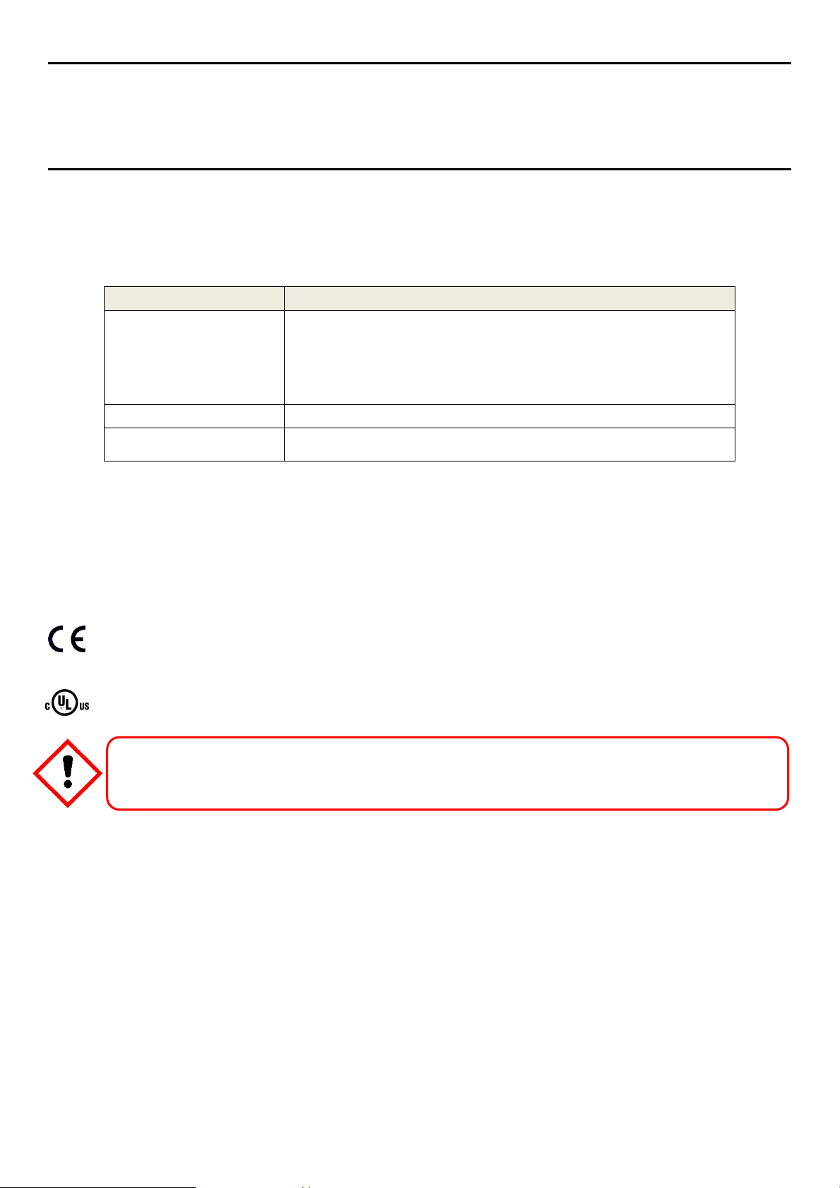
Products bearing the CE mark conform to all applicable European Directives as stated on the Honeywell
product specific EC Declaration of Conformity.
Products bearing the UL mark conform to the requirements for Ordinary Locations. The letters C and US
mean that the product is certified for use in Canada and the United States of America.
EN ENTIER AVANT D’UTILISER, D’ENTRETENIR OU DE RÉPARER L’ÉQUIPEMENT.
1

3020M5001_Iss 1_07/18 Touchpoint Plus Wireless
WARNINGS
1) The equipment specified in this manual is only to be installed by the Manufacturer’s trained personnel,
or by competent persons trained in accordance with the Manufacturer’s installation instructions.
2) Installation must be in accordance with the recognized standards of the appropriate authority in the
country concerned. Refer to local, national and company regulations.
3) Do not operate the Touchpoint Plus system or its components outside of their rated operating
specification.
4) Touchpoint Plus must not be operated in Oxygen enriched atmospheres, i.e. greater than 25% v/v
Oxygen.
5) All equipment containing a User Interface must be suitably protected from direct sunlight and rain.
6) Power Supply Fluctuations are not to exceed DC 18 – 32 V SELV Supply or ±10 % of nominal.
7) All versions of Enclosure apparatus are electrical Class 1, and must be connected to Protective Earth
(Ground).
8) The Touchpoint Plus installation must include a means of isolating or disconnecting the input voltage
supply. The isolation or disconnection device must be conveniently located close to the system and
be clearly labelled. For an AC mains voltage supply, the isolation or disconnection device must
disconnect both the line and neutral poles, but maintain earth (ground) continuity.
9) The Touchpoint Plus input voltage supply must include over-current protection.
10) All cabling must be appropriately rated and approved in accordance with local, national and company
regulations, and suitable for the installation. Additionally, cabling must satisfy requirements defined
in the manuals of connected field devices, in particular if the field device is certified for use in a
hazardous location.
11) All signal cables and interconnections must be shielded and the shields terminated only at the unified
earth (ground) bus bar situated inside the enclosure
12) All conduits and cable armour shall be bonded to protective earth (ground), and care must be taken
to avoid ground loops and to avoid contact with cable shielding.
13) Cable entry glands, blanking plugs, reducers, adaptors and breather devices must be suitably
approved and must not reduce the IP rating or protection levels. Items should not be used if there is
a high risk of mechanical damage to the equipment or enclosure.
14) Access doors and entry points must be kept closed when the system is energised in normal operation.
15) Enclosure locking handle security screws must be fully tightened during normal operation.
16) All equipment in this manual is rated to +2000 m (6562 ft) altitude maximum.
17) For safety reasons this equipment must be operated by qualified personnel only. Read and
understand the Instruction Manual completely before operating or servicing the equipment.
18) Touchpoint Plus systems may contain hazardous live terminals. Appropriate precautions should be
taken during operation, installation, and maintenance and servicing. Specifically, operators must
have appropriate training and experience to be aware of the hazards to which they may be exposed,
and of measures to minimise risk to themselves or other people.
19) The protection provided by the equipment may be impaired if the equipment is used in a manner not
specified or authorised by the manufacturer.
Technical Handbook
Important Safety Information
2
3020M5001_Iss 1_07/18 Touchpoint Plus Wireless
WARNINGS
20) Be aware that extended exposure of a detector element to certain concentrations of combustible
gases and air can introduce stress to the element that may seriously affect its performance, and
therefore recalibration should be carried out or the sensor replaced, or both, after an alarm due to an
indication of a high concentration.
21) When used in a Gas Detection summing up role, the gas reading may be higher than the actual
concentration at any one detector head location, or it may be the actual concentration at one specific
detector head.
Important
Chapter 1 Personnel, who work on, or in the area of, the Touchpoint Plus Gas detection system must be made aware of
– Safety – Safety.
Technical Handbook
Important Safety Information
1.1 Cautions
1) Touchpoint Plus SMPS and Input / Output Modules have no user serviceable parts. In the unlikely event
of a failure, the item must be replaced using only manufacturer supplied parts.
2) Do not use sharp objects to operate the touchscreen as this could irreparably damage the User Interface
and adversely affect its IP rating.
3) Use only soft, damp cloths or screen wipes to clean the Touchpoint Plus. Do not use solvents or abrasives
as they will damage the User Interface.
4) Once commissioned, Touchpoint Plus is intended for continuous operation.
5) Undo the security screws before pulling the locking handle. Failing to do so may irreparably damage the
enclosure.
1.1.1 Intended Readers
This Manual should be read by everyone who operates or monitors the Touchpoint Plus gas detection system.
Only personnel who have been fully trained by Honeywell are authorised to Install, Set-up, Service, and Test,
Repair, or Recondition Honeywell gas detection systems.
3

3020M5001_Iss 1_07/18 Touchpoint Plus Wireless
Technical Handbook
Important Safety Information
1.1.2 Conventions Used
The following conventions are used in this manual:
‘Start up’ refers to the action of switching on the system ready for use.
‘Restart’ refers to cycling the power off and then on again.
‘Boot up’ refers to the action of starting the software from cold.
‘Reboot’ refers to shutting down and restarting the software without interrupting the power supply.
‘TPPL’ refers to Touchpoint Plus
1.1.3 Associated Manuals
This manual should be used in conjunction with any manuals provided with ancillary components and
sensors.
This manual is available in 14 user languages:
Chinese (Simplified)
Dutch
English
French (Canada)
French (France)
German
Italian
Japanese
Korean
Portuguese (Brazil)
Portuguese (Portugal)
Russian
Spanish (Mexico)
Spanish (Spain)
4

3020M5001_Iss 1_07/18 Touchpoint Plus Wireless
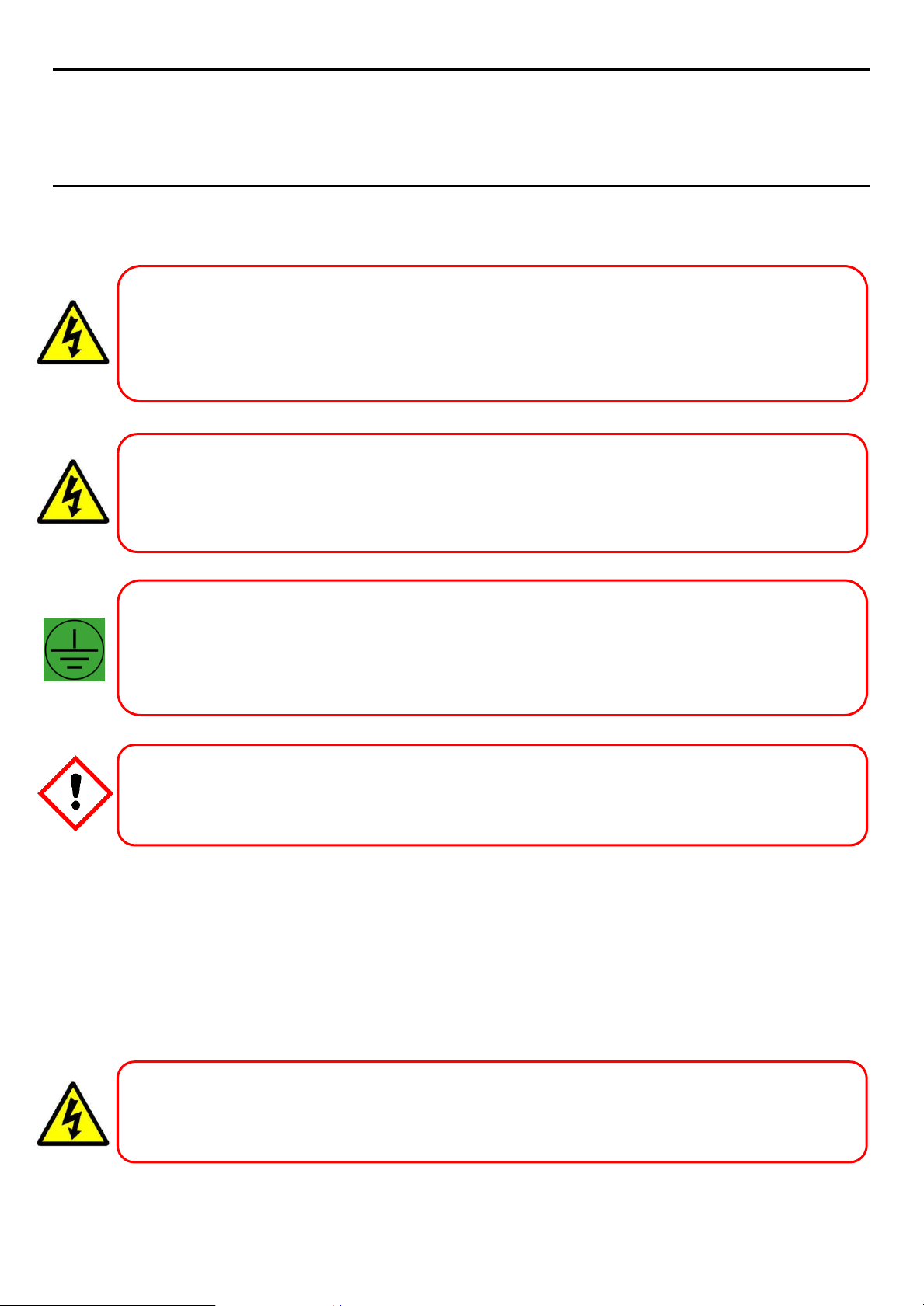
Danger
Indicates an imminent hazard that, if not avoided, is extremely likely to result in death or serious injury.
Warning
Indicates a potentially hazardous situation that, if not avoided, could result in death or serious injury.
Caution
Indicates a potentially hazardous situation that, if not avoided, may result in minor or moderate injury. It is also
used to alert the user against unsafe working practices and potential damage to equipment.
Technical Handbook
Safety Hazards, Warnings And Cautions
Chapter 2 – Safety Hazards, Warnings and Cautions
2.1 Safety
Incorrect set-up, maintenance, operation or modification of the Touchpoint Plus gas detection system or its
installation may constitute a serious hazard to the health and safety of personnel and their environment. It is
therefore imperative that the contents of this chapter are thoroughly understood by everyone who has access
to the gas detection system or its associated equipment.
When properly installed, this gas detection system enclosure is rated as IP65.
It may be installed in a Pollution Degree 2 (i.e. laboratory, office or control room) or Pollution Degree 3 (i.e.
unheated boiler room) environment as defined by IEC/UL/EN 61010–1: Safety requirements for electrical
equipment for measurement, control and laboratory use.
In all cases, several hazards may be present when operating or servicing the equipment and extreme caution
must be exercised at all times. The hazards that may be encountered include:
Class 1 electrical hazards (AC 110/220 V, DC 18–32 V)
Mechanical hazards (Heavy components, swinging access doors)
Environmental hazards (toxic atmospheres)
Fire and Ignition hazards (Touchpoint Plus is not ATEX/IECEx Zone 1 certiified, and cannot be used in
flammable atmospheres, or where oxygen concentrations >25% v/v O2)
2.1.1 Warnings and Cautions
Safety of this equipment is reinforced by the use of safety labels that are fixed to the equipment in a visible
manner. The type of safety labels used and their location is detailed in this chapter. The degree of
seriousness of the hazard is indicated in this manual by the use of the following signal words accompanied by
a suitable hazard symbol:
5
3020M5001_Iss 1_07/18 Touchpoint Plus Wireless
Danger – Ignition Hazard
Warning – Lethal Voltage Present
Warning – Lethal Voltage Present
Warning – Lethal Voltage Present
Warning – Toxic Waste and Harmful By-Products
The Touchpoint Plus system and/or its sensors may become contaminated by the ambient environment in which
Technical Handbook
Safety Hazards, Warnings And Cautions
2.1.2 Safety Hazards
The following specific hazards are associated with the installation and use of this equipment:
Touchpoint Plus is Not ATEX/IECEx certified, and it may only be installed in safe areas where there are no
flammable atmospheres, and no oxygen concentrations >25% v/v O2.
All power supplies must be hard wired and must include a circuit breaker (RCD / RCCB) and, close by and
unobstructed, a means of manually isolating and locking–out the power supply without breaking the protective
earth (ground) connection.
Removable plug/socket connection is not permitted under any circumstance.
Lethal current may be present in this equipment when electrical power is applied. There is a danger of death or
injury from electrical shock. Isolate power before opening electrical access panels. Ensure residual current is
fully discharged before touching live terminals.
Lethal current may be generated both internally and externally to the system. All installations, including
enclosure, external units, must be grounded to protective earth, and must be capable of staying earthed
(grounded) when the power supply is interrupted.
The Protective Earth (Ground) symbol is shown to the left, and always has a green background. Do not confuse
it with the chassis earth symbols shown below it.
it or they are used. It is the Customer’s sole responsibility to ensure that all appropriate safety precautions are
taken before handling any components or transferring them to any other party.
6
3020M5001_Iss 1_07/18 Touchpoint Plus Wireless
Warning – DO NOT USE WATER
Evacuate the area and call Emergency Services.
Caution – Risk of Eye Injury
Caution – Risk of Hearing Damage
Warning – Fire or Explosion Hazard
Caution – Health and Environmental Hazards
disposed of.
Caution – Risk of Injury and Damage
is fitted securely to a suitable surface.
Technical Handbook
Safety Hazards, Warnings And Cautions
2.1.2 Safety Hazards (Cont.)
The following general hazards are associated with the use of this equipment:
This equipment contains a number of potentially toxic substances that may pose a health or environmental
hazard if exposed to very high temperatures, VOCs or corrosives, or if improperly handled or carelessly
Each Touchpoint Plus enclosure is heavy and weighs considerably more when packed. Ensure that a Manual
Handling Risk Assessment is carried out before moving or installing the system, and ensure that the enclosure
Touchpoint Plus uses high energy AC and DC currents that may cause arcing and sparks if shorted out. Always
Touchpoint Plus can be used to control loud alarms and sirens. Always wear hearing protection when working
Battery may explode if mistreated. Do not disassemble or dispose of in fire.
DO NOT USE WATER if a lithium battery overheats or burns,
as this may make the fire worse and may cause an explosion.
wear eye protection when the enclosure is open.
in the vicinity of loud noises.
7
3020M5001_Iss 1_07/18 Touchpoint Plus Wireless
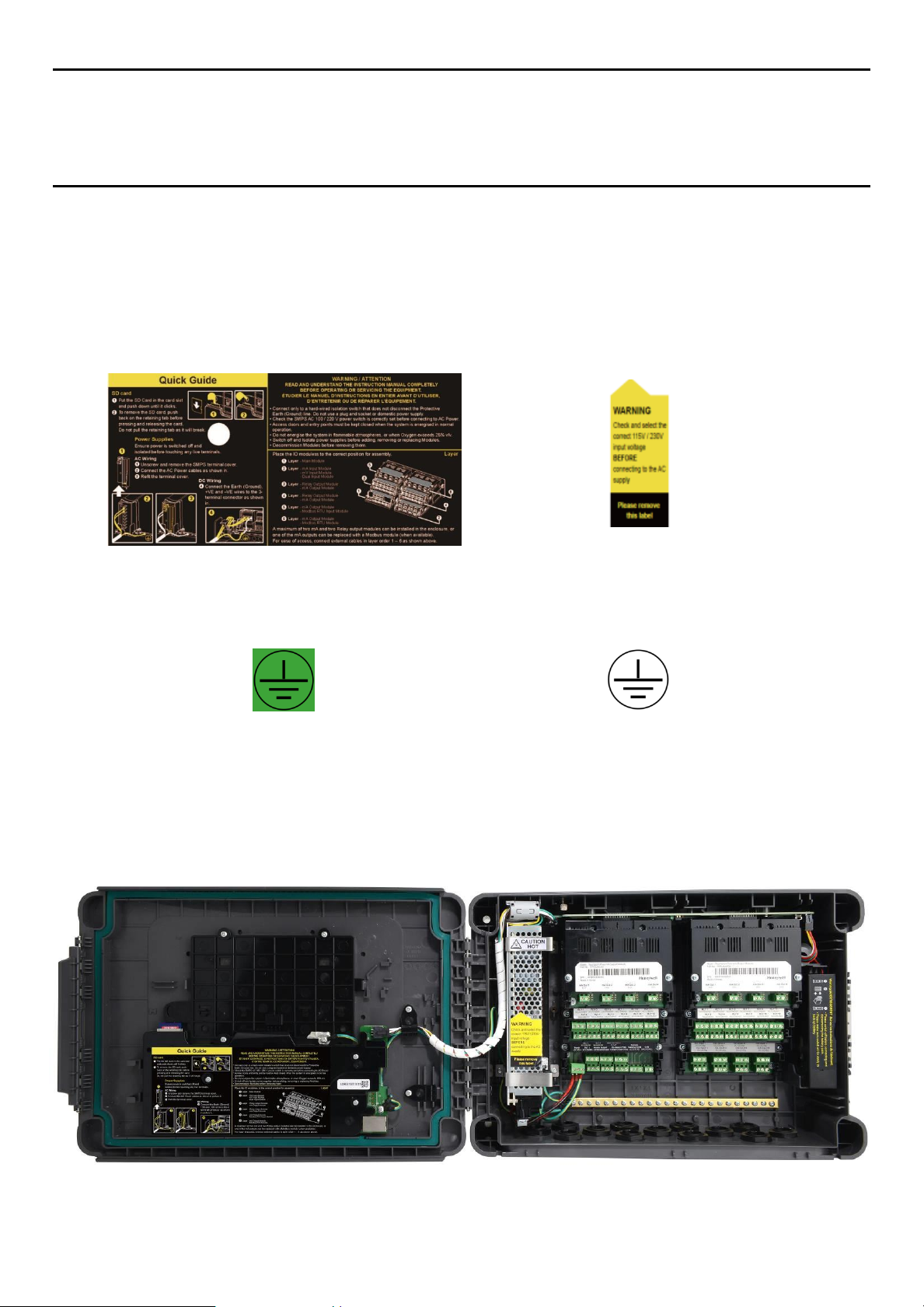
Figure 1. Quickstart Guide Label
(Not to Scale)
Figure 2. SMPS Voltage Warning Label
(Removed During Installation)
Figure 3. Protective Earth (Ground) Point
Figure 4. Equipment Earth (Ground) Point
This Protective Earth (Ground) location point label is
used inside the system and is not normally visible to
the operator.
This Equipment Earth (Ground) location point label is
used inside the system and is not normally visible to
the operator.
Technical Handbook
Safety Hazards, Warnings And Cautions
2.2 Location and Description of Warning Labels
2.2.1 Safety Warning Labels
In accordance with the requirements of the European Standard EN 60825–1, appropriate warning labels are
mounted in specified locations on the equipment. This is to indicate conditions under which the user could be
subjected to electrical hazards.
8
Figure 5. Internal Label Positions

3020M5001_Iss 1_07/18 Touchpoint Plus Wireless
Warning – Unauthorised Personnel
manufacturer’s warranty.
Anti–Static Precautions
Technical Handbook
Safety Hazards, Warnings And Cautions
2.3 Electrical Hazards
Gas detection systems contain electrical supplies that are potentially dangerous and hence precautions must
be taken to prevent the risk of electrocution.
2.3.1 General Precautions
Read the relevant manual before beginning any operating or service procedures.
Only personnel trained and certified by Honeywell are authorised to service, fit or remove internal parts.
Only the minimum number of trained personnel, consistent with safety, should have access to the area
while work is being carried out. If necessary, erect warning signs and barriers.
Follow accepted working procedures and codes of practice as well as the electrical safety code for the site
where the equipment is installed.
Never operate the equipment under normal conditions with access panels removed or shorting links fitted.
Do not ‘Live Test’ without a Safe System of Work (SSoW).
Always keep the area around the equipment dry and free of obstructions.
Switch off and Isolate the equipment if water ingress is suspected or confirmed.
Never operate the equipment if any Mains power cable is frayed or damaged.
Never wear wristwatches, rings, bracelets, or other jewellery when working around electrical circuits or
moving parts.
Take anti-static precautions when working on electronic circuits.
Never work on electrical equipment alone.
2.3.2 Component Testing and Replacement
Before carrying out any electrical testing or component replacement:
Read this Manual to become familiar with the location of high voltage components.
Isolate the system at the main circuit breaker, lock it in the ‘Off’ position, and attach a notice indicating
that maintenance work is in progress.
Always wait for 5 minutes after isolating the equipment to ensure that stored energy has dissipated.
Never assume the polarity of cabling or replacement components. Refer to electrical schematics or
contact Honeywell for confirmation.
Use only Honeywell approved replacement parts.
Only Honeywell trained and certified maintenance technicians are authorised to carry out component testing
and replacement. Unauthorised work may result in a potentially dangerous situation and will invalidate the
Antistatic Precautions are required to prevent severe damage to electronic components.
9
3020M5001_Iss 1_07/18 Touchpoint Plus Wireless
Important
If installed correctly, the equipment earth (ground) point is connected directly to mains earth (ground) via
protective earth and the mains power supply cable. It is not dependent on the position of the Isolator switch or
circuit breaker.
Lithium Battery Toxic and Fire Hazards
in accordance with local regulations.
Technical Handbook
Safety Hazards, Warnings And Cautions
2.3.3 Antistatic Precautions
As with all modern electronic circuits, the Printed Circuit Boards (PCBs) in Touchpoint Plus systems utilise
some static-sensitive components that can be severely damaged if subjected to static discharge. Static can be
generated on the human body by friction or movement and is discharged through the first contacted route to
earth. It can also jump gaps between items of differing electrical potential.
Static damage is not always immediately apparent and can cause component failure at any time after the
static discharge has occurred. It is, therefore, very important that everyone takes the following precautions
when handling PCBs:
An industry approved antistatic wrist strap, containing a resistive component greater than 1Megohm, must
be worn and connected to an effective earth (ground) point. The continuity between the strap and earth
(ground) must be checked regularly.
PCBs must only be handled by their non-conductive edges. Do not allow any components, conductive
tracks or contacts to come into proximity with the body, clothing, machinery, power source or any material
other than a static-dissipative mat.
With the exception of assemblies containing batteries, anti-static packaging must be used for transporting
PCBs and Integrated Circuits (ICs). All Touchpoint Plus electronic components are shipped in appropriate
packaging that can be re-used when returning items for test or repair.
Avoid wearing clothing manufactured from, or containing a high proportion of, man-made fibres. These
can build up a high static potential that may not be discharged through the body or wrist strap.
An effective earth (ground) point is the protective earth (ground) bus bar inside the enclosure. This can be
used to connect a suitable anti-static wrist strap provided that the Gas detection system is connected to
protective earth (ground) via the mains power supply cable.
2.3.4 Good Practice
After switching off the system, it is good practice to wait at least 15 seconds before switching it on again. This
allows the circuits and RAM to discharge adequately before being powered-up again. Failing to do so may
cause data corruption.
2.3.5 Lithium Battery Hazard
Lithium batteries are fitted to Touchpoint Plus as backup power sources.
Replace the battery pack with Honeywell Analytics part no. TPPLOIBB(order number:TPPLSIBB) and the
PCB coin battery with type CR2032 only.
Use of other batteries may present a risk of fire or explosion.
Lithium batteries may cause severe injury or death if ingested, and may catch fire or explode if mishandled,
recharged, burned or disposed of incorrectly.
Always handle lithium batteries with care, keep them out of the reach of children, and dispose of them carefully
10
3020M5001_Iss 1_07/18 Touchpoint Plus Wireless
Safety
Compliance to
Electrical Safety
CSA C22.2 No.61010-1 and No.142
UL 61010-1 3rd Edition and UL 508
IEC/EN 61010-1 3rd Edition
ANSI/ISA 12.12.01-2015
CAN/CSA C22.2 No. 213-16
EMC/RFI
EN 50270
Low Voltage Directive
IEC/EN 61010-1 (3rd Edition)
Important
Technical Handbook
Safety Hazards, Warnings And Cautions
2.4 Product Compliance
This product complies with the following standards and directives.
Other safety directives may apply to the complete system installation if an OEM’s product is integrated into
other equipment or machinery.
Note: The Equipment referred to in this manual contains components and assemblies that are each certified
for use in a variety of differing environments, and it is the site owner’s responsibility to confirm the suitability of
the equipment prior to its installation and use.
Please check the product rating plate and look for the following marks to ensure that the supplied
equipment is suitable for its intended location and purpose:
Products bearing the CE mark conform to all applicable European Directives as stated on the Honeywell
product specific EC Declaration of Conformity.
Products bearing the UL mark conform to the requirements for Ordinary Locations. The letters C and US
mean that the product is certified for use in Canada and the United States of America.
Read and understand the instruction manual before operating or servicing the equipment.
2.5 Conditions of Use
This Touchpoint Plus equipment should only be operated under the following circumstances:
By properly trained personnel.
Under approved conditions.
With due authorisation.
Using approved maintenance and servicing procedures.
2.5.1 Training of Personnel
Honeywell and / or its distributors can provide training for operators and maintenance personnel. Personnel
who have been trained in operation and maintenance shall be limited to carrying out only those procedures
and tasks taught during the training course. Honeywell certified maintenance technicians must carry out all
other tasks.
Honeywell can also provide additional or advanced training. Retraining is recommended periodically and
2.5.2 Conditions Satisfying Local, National and International Safety Regulations
11
whenever equipment is upgraded.

3020M5001_Iss 1_07/18 Touchpoint Plus Wireless
Technical Handbook
Safety Hazards, Warnings And Cautions
Approved conditions must satisfy the requirements of applicable national and international safety standards
and statutory requirements relating to electrical, EMC, and health hazards. In addition, they must satisfy the
requirements of the Site Safety Officer and the local safety regulations.
2.5.3 Due Authorisation
Before any production, maintenance, or servicing procedure is carried out; written authorisation must be
obtained from one of the following personnel to confirm that the proposed task satisfies the necessary safety
conditions:
A competent authorised person having a professional qualification in an appropriate technical discipline.
The Factory, Technical or Engineering Manager responsible for the working area.
The Site Safety Officer or an authorised Honeywell representative or approved distributor.
2.5.4 Approved Maintenance and Servicing Procedures
Approved Maintenance and Servicing Procedures are those stipulated in this manual or as authorised
separately by Honeywell.
It may be necessary to establish a temporary Locally Controlled Area (LCA) to restrict access during
maintenance, testing or service of this equipment.
12
3020M5001_Iss 1_07/18 Touchpoint Plus Wireless
Technical Handbook
System General Description
Chapter 3 – System General Description
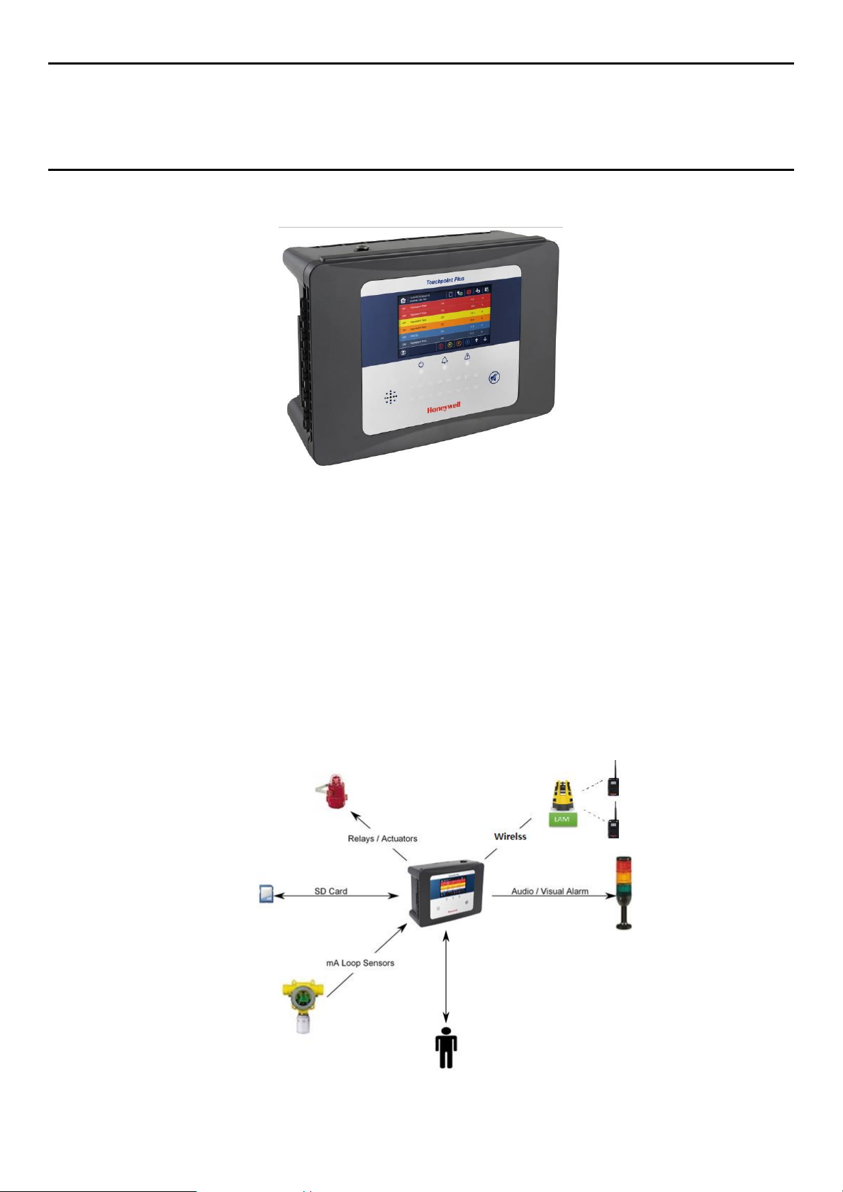
Figure 6. Touchpoint Plus Wall-Mounted Controller
The Touchpoint Plus is an entry level (or upgrade) touch-screen digital Controller for general industrial and
commercial gas detection systems. It has eight input channels, with a further eight channels available through
an expansion unit*.
It can handle a wide range of milliamp, millivolt, and catalytic sensors through analogue inputs, and it can
control various outputs such as audible and visible signals and solenoid valves.
The cabinets are constructed from high-impact plastic and have fully-sealed, easy opening access. They are
supplied with a wall mounting or can be directly mounted to any solid vertical surface or rack. Cable entry is
via entry glands on the lower side.
Touchpoint Plus is rated IP65, which means that it is dustproof and can be subjected to low-pressure water
without significant ingress. This makes it particularly suited to offices, control rooms and unheated boiler
rooms.
*Currently Touchpoint Plus is only available as a stand-alone Gas Detection System, but please contact
Honeywell Analytics for details about future upgrades. (The expansion unit is currently planned for release in
end of 2015.)
Figure 7. Typical Installation Options
13
3020M5001_Iss 1_07/18 Touchpoint Plus Wireless
Technical Handbook
System General Description
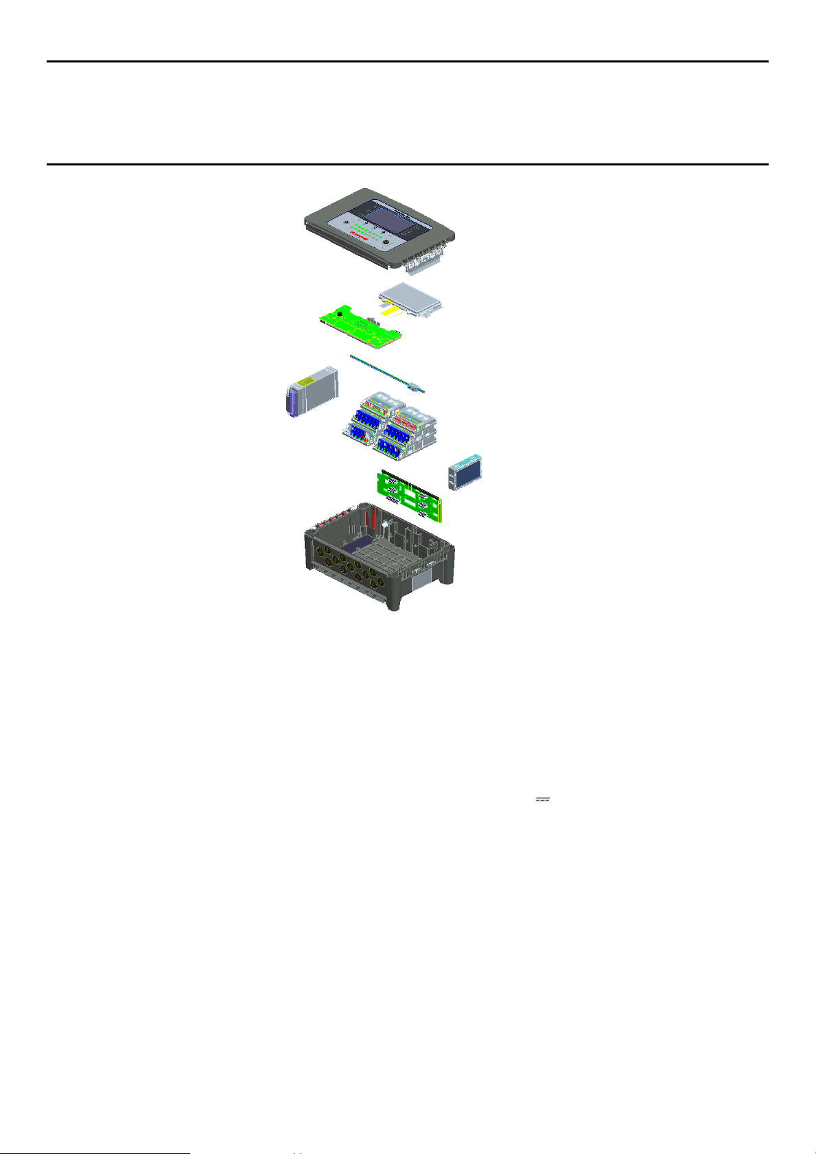
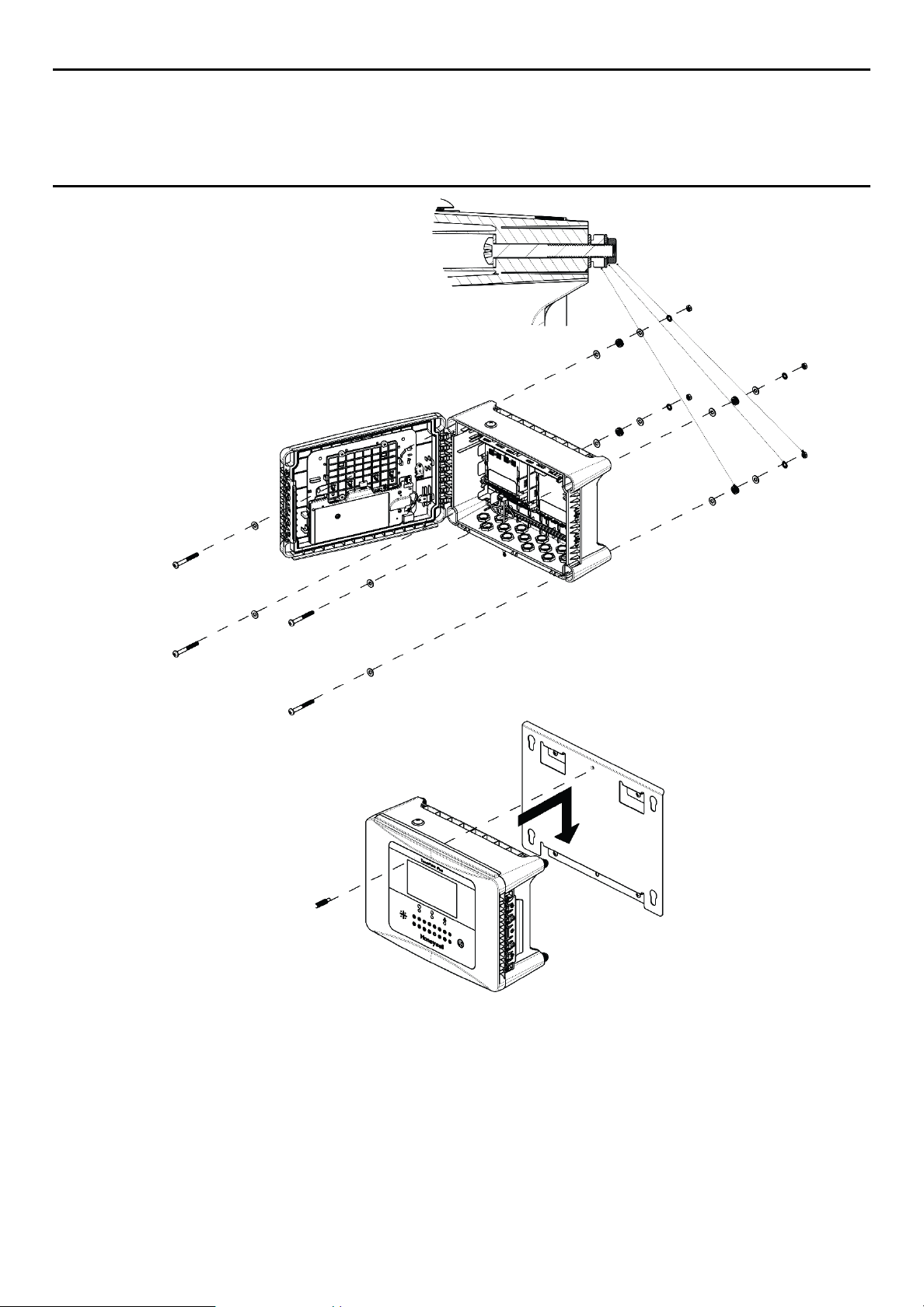
Figure 8. TPPL Controller Exploded View
Both the Touchpoint Plus and its optional expansion unit have the option for AC, DC and battery backup
power supplies.
Other features:
Colour LCD Touch Screen with multi-language GUI and menus
Password protection
Flexible Mains Power Input: 50 – 60 Hz 110/220V ~ (AC), 18 – 32V (DC), Max 105W
Up to 8 channels of Analogue Input (0–22mA)
2 or 3-wire signal inputs
Up to 12 channels of user configurable relay controlled Output
Alarm update on Acknowledge
Automatic Self-Diagnostic with error codes
Event recording
SD Card
14
3020M5001_Iss 1_07/18 Touchpoint Plus Wireless
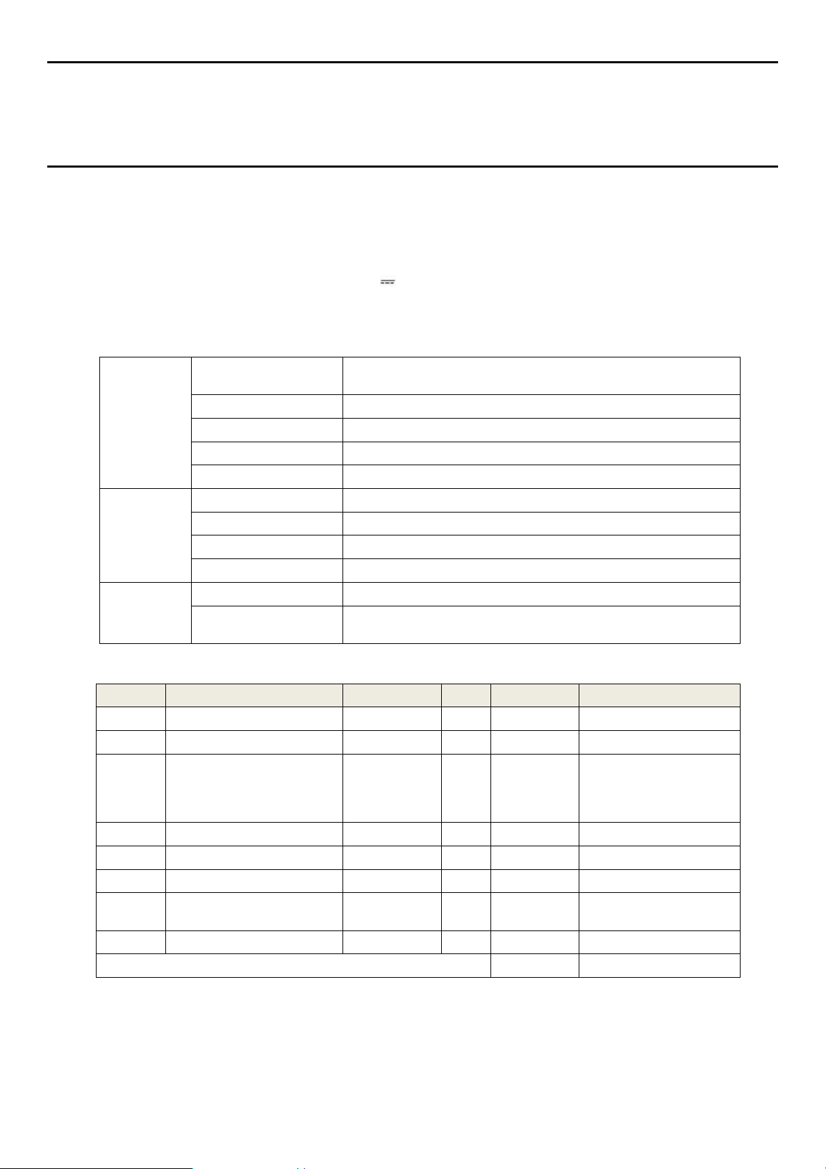
Input
Voltage Range AC
AC 110/220 V manually switchable
300 VAC surge for 5 sec without damage
AC Frequency Range
50 – 60 Hz ± 6%
AC Current Draw (typ.)
3 A @ 115 VAC, 2A @ 230 VAC
Cold-start Current (typ.)
40 A @ 230 VAC
Leakage Current
<2 mA @ 240 VAC
Output
DC Voltage
24 V
Rated Current
6.5 A
Current Range
0 – 6.5 A
Rated Power
156 W
Protection
Overload
110 – 150 % rated output power
Over-Volt
27.6 – 32.4 VDC Hiccup mode, which recovers automatically when
the fault is removed.
No
Modules
mA @ 24 VDC
Qty
Power (W)
Remarks
1
UI Module
0.17
1
4.06
Max
2
Main Module
0.16
1
3.84
Max
3
mA Input Module
0.05
1
1.14
Eight channel module.
(not including detector
power)
4
mA Field Device Power
5 8 40 5
WIO Module
6
Relay Output Module
0.12
2
5.77
Max
7
Charging power for backup
battery pack
0.38
1
9.12
Max
8
Audio/Visual Alarm
0.3
4
28.80
MAX TOTAL
97.4
Technical Handbook
System General Description
3.1 Equipment Specification
3.1.1 Power Requirements
The Touchpoint Plus system is designed to operate on a single phase, 50 to 60 Hz, 110/220 V~(AC) supply
with a typical power consumption of less than 105 W.
Alternatively it can be connected to a 18–32V (DC) supply with a typical power consumption less than
105W
The system can contain an optional backup battery to guard against short-term power disruption.
Table 1. Power Supply (SMPS RS–150–24) Electrical Ratings
Table 2. System Power Calculations
15
3020M5001_Iss 1_07/18 Touchpoint Plus Wireless
TPPL basic unit
Remark
System alone
8.5 Kg (18.7 lbs)
System with packaging
9 Kg (20 lbs)
External Dimension
Millimetres
Inches
Depth
156
6.2
Length
426
16.9
Width
300
11.8
Technical Handbook
System General Description
3.1.2 Weights
Table 3. System Weights
Note: One input module, one relays, one WIO module, AC power and backup battery based for basic
3.1.3 Dimensions
Table 4. System Dimensions
3.1.4 Ambient Operating Temperature
–10 °C to +55 °C (14 °F to 131 °F)
3.1.5 Overall Ambient Operating Humidity
5 % to 95 %RH, non-condensing
3.1.6 Storage Conditions (Without batteries)
–25 °C to +60 °C (-13 °F to 140 °F), @ 5 % to 95 %RH, non-condensing
3.1.7 Storage Conditions (With batteries)
1 year: –20 °C to +25 °C (–4 °F to +077 °F)
3 months: –20 °C to +45 °C (–4 °F to +113 °F)
1 month: –20 °C to +60 °C (–4 °F to +140 °F)
3.1.8 IP Rating
The system and expansion unit are sealed to IP65 when appropriate cable entry glands are used.
3.1.9 Construction
The system cabinets are constructed from PC ABS plastic with a secured quick release front access door
panel.
The Controller door panel holds a touch sensitive colour LCD with a membrane cover over additional buttons,
LEDs and an audible warning horn.
Inside the Controller cabinet is a Switched-Mode Power Supply (SMPS) providing a nominal DC 24 V output,
an optional Lithium-ion backup battery, a Main Module, a mA/mV Input Module, one Relay
Modules, protection fuses, and the control and user interface electronics.
The optional expansion unit (available end of 2015) holds the same modules and optional backup battery, but
has no controller or user interface.
Both cabinets contain a common Earth (ground) rail that must be bonded to Protective Earth (Ground) through
an isolation switch that does not disconnect the Earth line.
16
3020M5001_Iss 1_07/18 Touchpoint Plus Wireless
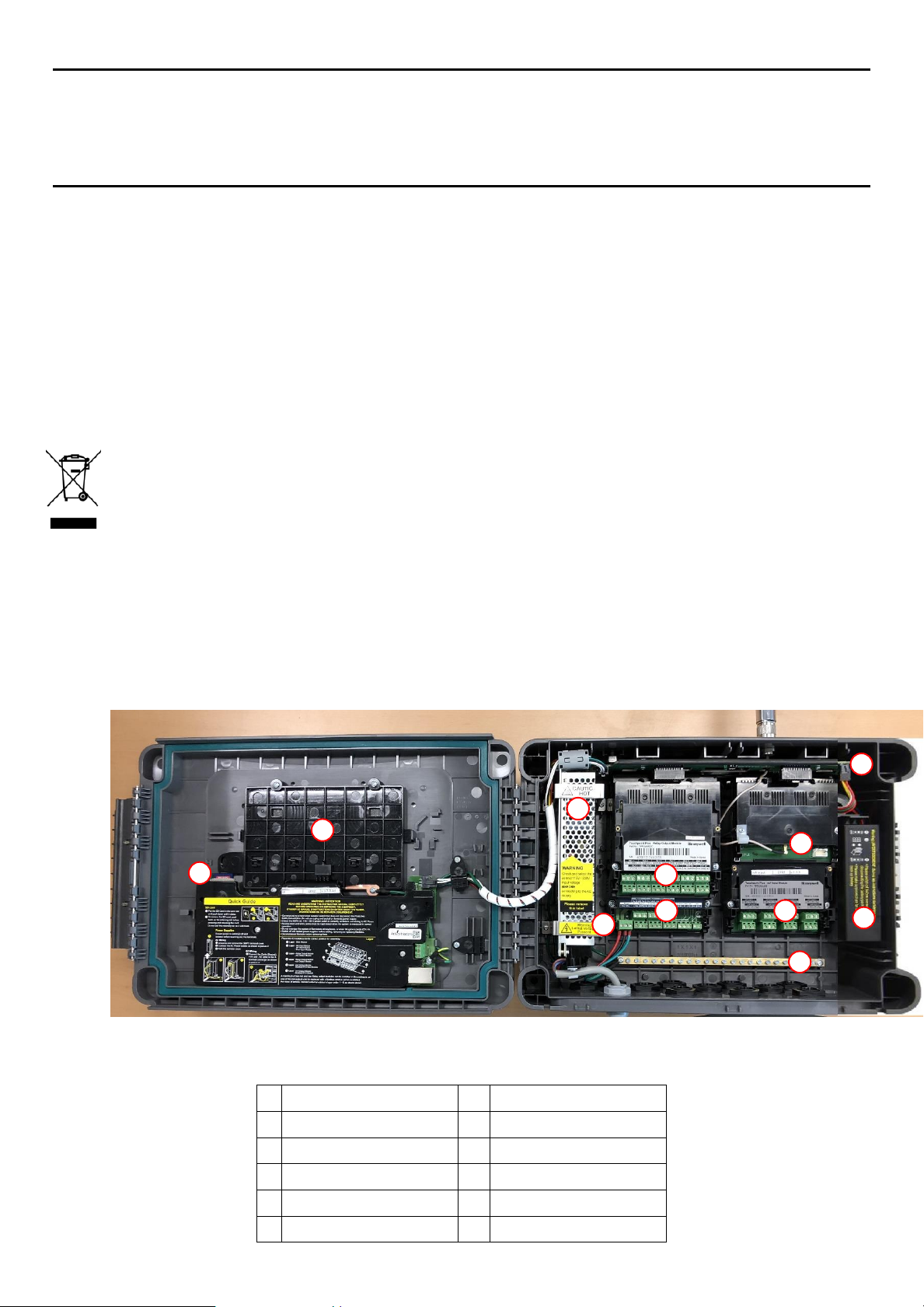
1
Touchscreen
7
Main Module
2
SD Card
8
mA Input Module
3
SMPS
9
NA
4
WIO Module
10
Earth (Ground) Bus Bar
5
Relay Output Module
11
Battery On / Off Switch
6
Power Terminal
12
Backup Battery
1 2 3
5
7
6
10
Technical Handbook
System General Description
3.1.10 Touchpoint Plus Packaging
Touchpoint Plus outer packaging is made from cardboard. Facilities for recycling are widely available.
Touchpoint Plus inner packaging is made from Stratocell®, Low-Density Polyethylene (LDPE) foam. The
foam can be recycled into new Stratocell® where such recycling facilities exist.
3.1.11 Packaging Components for Return to Manufacturer
Honeywell is unable to accept any consignment that does not conform to the European Classification,
Labelling and Packaging (CLP) Regulations (EC) 1272/2008.
Please consult your distributor, supplier, or the manufacturer if you require further advice.
3.1.12 Disposal (WEEE Directive)
The system contains Lithium batteries and a number of homogenous hazardous materials. These should be
disposed of carefully in accordance with the WEEE Directive and local laws and guidelines. Under no
circumstances can they be disposed of as domestic waste.
3.2 System Construction
This figure shows the basic building blocks of the Touchpoint Plus system. The optional Expansion Unit will
not have any of the items seen on the left hand (door) panel.
Figure 9. System Layout Before Installation
17
3020M5001_Iss 1_07/18 Touchpoint Plus Wireless
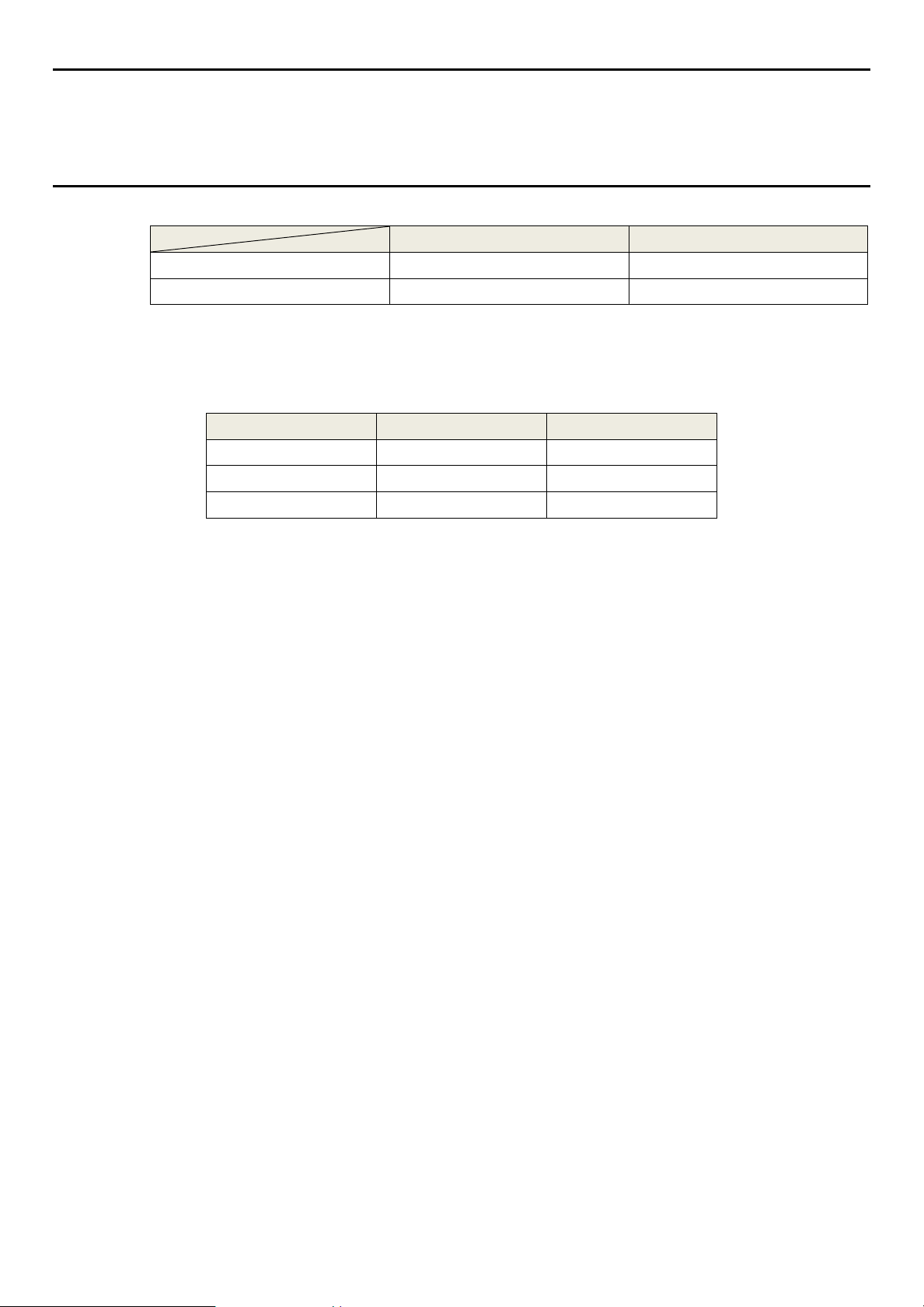
Assembly
IP
NEMA
Pollution Degree
Remarks
Wall mounted cabinet
65
4X
2
When properly installed using the
appropriate cable entry glands
Caution
It is the Customer’s responsibility to ensure that the equipment is correctly installed, and that cable entry glands
Caution
Technical Handbook
System Mechanical Installation
Chapter 4 – System Mechanical Installation
The system can be directly wall-mounted, mounted on an optional mounting fixture.Whichever method is
chosen, the mounting must be sound, secure, and capable of supporting the weight of the enclosure plus the
weight of any cables and glands.
When choosing a location, it must be easily visible and accessible, with room to mount an external power
isolator. There must also be room to fully open the access door, which opens to the left, and room to easily
access the door locking handle and its securing screws, which are situated on the right. If using the expansion
unit (available end of 2015), there must be room to mount both boxes side-by-side with space between them
to access the locking handle and its securing screws.
The units should be mounted so that the screen can be easily accessed and seen, but they should not
obstruct accesses, walkways or exits.
Although the units are IP65 when installed correctly, they should be mounted away from heat sources, out of
direct sunshine, and should be protected from rain, severe weather, steam or excess humidity and
condensation.
These units have only passive cooling, so an adequate airflow must be maintained to prevent overheating.
Failure to do so will invalidate the quoted IP / NEMA / Pollution ratings and may invalidate the warranty.
The units as supplied have two hex-socket securing screws in the access door handle, and these have to be
undone prior to opening the handle. Failing to do so could cause irreparable damage to the housing.
The handle must be correctly locked and the screws must be correctly tightened when the unit is in operation.
Failing to fully secure the enclosyre is unsafe and will invalidate product certification.
or blanks of the appropriate IP rating are correctly used.
18
3020M5001_Iss 1_07/18 Touchpoint Plus Wireless
1 2 3
Technical Handbook
System Mechanical Installation
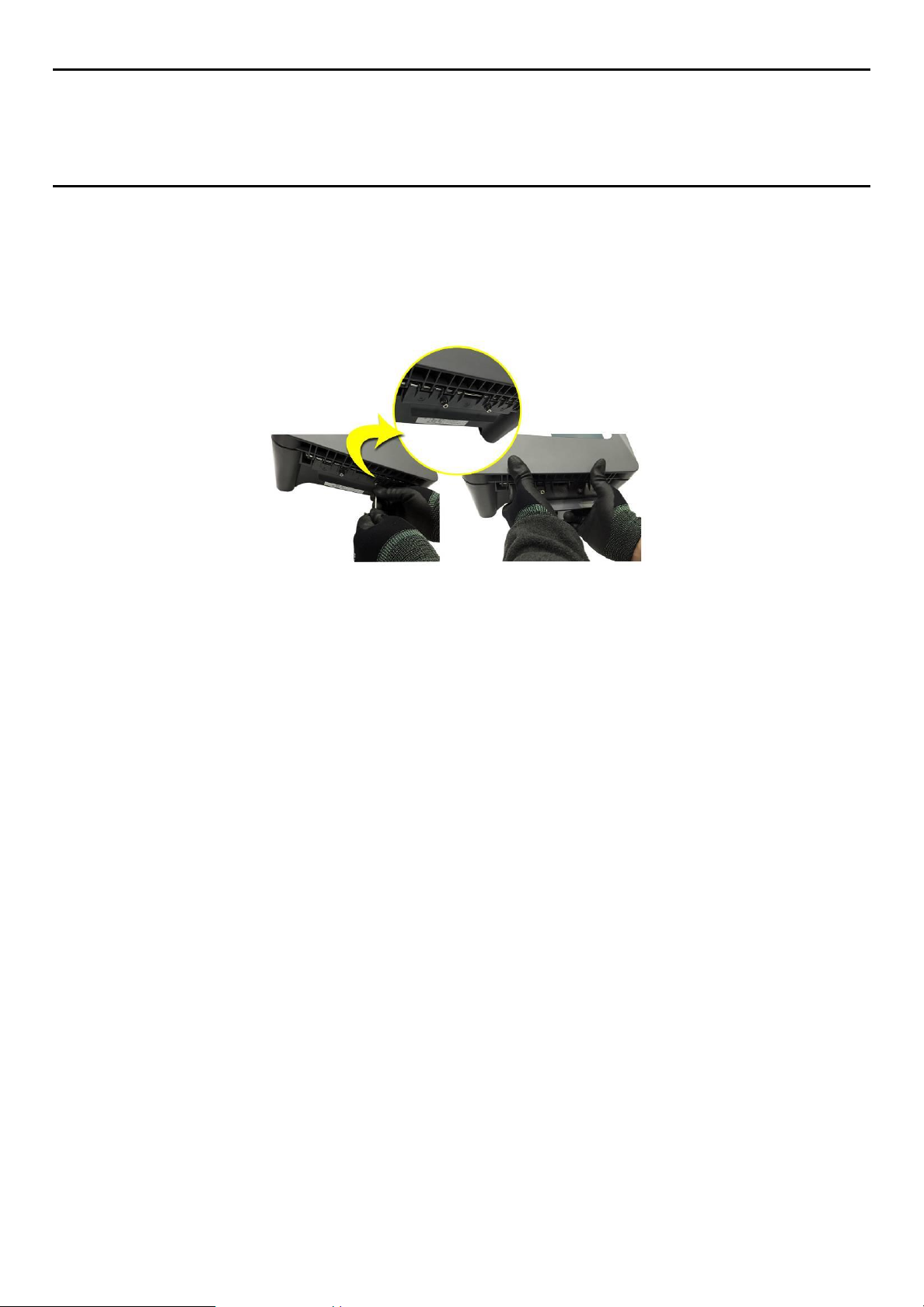
4.1 How to Open and Close the Enclosure
1) Ensure that it is safe to open the enclosure and, if necessary switch off and isolate electrical power.
2) Unscrew the two 3mm Hex socket security screws (1) until they become loose (2).
3) With a gloved hand only, pull the handle until it comes free (3). Do not apply undue force.
4) Open the enclosure door fully.
Figure 10. Undoing the Security Screws and Opening the Enclosure
5) Closure is the reverse of this procedure, but care must be taken not to exert undue force, and do not
press on the membrane or touch screen areas.
Note: The door recess has an environmental seal that requires some pressure to close the door correctly.
The enclosure handle is the primary method of applying this pressure but you can assist it by pressing on the
door edge directly above the handle as you press on the handle itself.
19
3020M5001_Iss 1_07/18 Touchpoint Plus Wireless
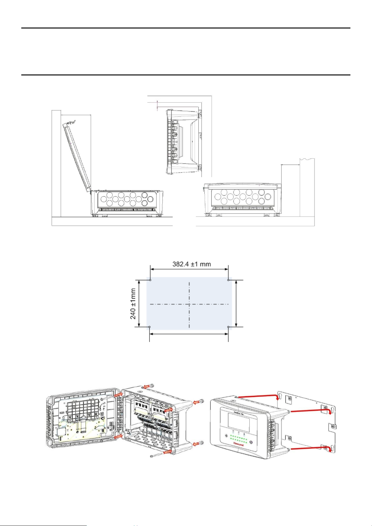
Minimum Wall
Clearance 175.5 mm
Minimum Wall Clearance 100 mm
Minimum Ceiling Clearance 20 mm
Technical Handbook
System Mechanical Installation
4.2 Wall Mounting Requirements
Figure 11. Installation Clearance Measurements
Figure 12. Wall Mounting Points
Figure 13. Wall Mounting Plate Option
20
You can use the wall mounting plate as a template and location guide, and you should ensure that the
mounting bolts are adjusted to fit the plate bayonet holes before fixing the plate to the wall.
3020M5001_Iss 1_07/18 Touchpoint Plus Wireless
Technical Handbook
System Mechanical Installation
4.2.1 Wall Mount Fixings
You will require the following locally sourced items to install the Touchpoint Plus:
Tool to undo the enclosure access handle security screws:
3 mm Hex key
Suggested Fixings to screw the enclosure to the wall only:
Screw Max. Dia: 6.4 mm (#14) dome or cheese head screw
Screw Min. Length: 76 mm (3 in.) – Normal fix
Washer Max. Dia: 14.3 mm (0.56 in.)
Note: The sizes above are given to allow for clearance in the TPPL Enclosure. The actual length and type of
fixing should be determined by the surface material and the type of anchor required.
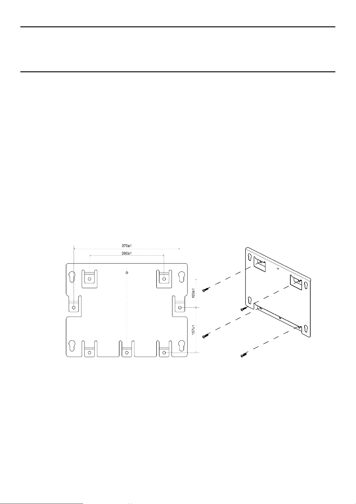
Suggested Fixings for using the Mounting Plate:
For the plate, choose fixings appropriate to the surface and the weight of the enclosure plus cables. You will
also need to use suitable bolts, washers and lock nuts (see diagram below).
21
3020M5001_Iss 1_07/18 Touchpoint Plus Wireless
Technical Handbook
System Mechanical Installation
Figure 14. Fixing Orientation When Using the Optional Mounting Plate
Note:
You should ensure that washers between the TPPL enclosure and the wall or mounting plate are sufficiently
large to spread the load evenly.
For metal conduit, use a metal ground plate (i.e. PN: TPPLOMGND).
For external visual/audio outlet, ensure IP65 is maintained (i.e. PN: M-700123).
For cable gland, use type PG16 and tighten to 44.2 lb-in torque.
22
3020M5001_Iss 1_07/18 Touchpoint Plus
Warning
The system is normally supplied with the voltage pre-set to the customer’s specification. If the supplied voltage
is incorrect, it must be altered prior to connecting to the mains power supply.
Warning – Electrical Shock Hazard
Warning – Electrical Shock Hazard
Warning – Electrical Shock Hazard
Warning
Technical Handbook
Electrical Power And Interfacing
Chapter 5 – Electrical Power Connection and Interfacing
All power supplies must be hard wired and must include a circuit breaker (RCD / RCCB), and (close by and
unobstructed) a means of manually isolating and locking out the power supply without breaking the protective
earth (ground) connection.
Removable plug and socket connection is not permitted under any circumstance.
Lethal current may be present in this equipment when electrical power is applied. There is a danger of death or
injury from electrical shock. Isolate power before opening electrical access panels. Ensure residual current is
fully discharged before touching live terminals.
Lethal current may be generated both internally and externally to the system. All installations, including remote
units and cables, must be connected to protective earth, and must be capable of remaining so when the power
supply is interrupted.
Protective earth is shown by the green symbol on the left.
Honeywell can accept no responsibility for any damage or injury caused by incorrect or faulty wiring.
5.1 Power Connection
The TPPL systems are factory set to operate at a manually switchable voltage of AC 110/220 V on single
phase, 50 to 60 Hz supplies. They can also be connected to DC 18 – 32 V SELV without backup battery or
DC 24 – 32 V SELV if using the backup battery option.
All systems have a typical peak power consumption of less than 105 W, and must be directly connected to
supplies via a Main Isolator Switch that leaves protective earth (ground) permanently connected. The circuit
should incorporate a Residual Current Device or Residual Current Circuit Breaker (RCD or RCCB).
TPPL systems are not certified for connection to domestic power supplies.
It’s customer’s responsibility to provide appropriate power supply to detectors and controller.
23
3020M5001_Iss 1_07/18 Touchpoint Plus Wireless
Wire
Europe
USA
CAN
India/Pakistan
Protective Earth (Ground)
Green + Yellow
Green
Green
Green
Isolated Earth (Ground)
—
Green + Yellow
Green
—
Neutral
Blue
White
White
Black
Line
Brown
Blue, Red, or Black
Red or Black
Red, Yellow, or
Blue
AC Line
AC Common
F – Ground (Not Used)
AC Input
DC Output
-Ve DC
-Ve DC
+24 VDC
+24 VDC
+24 V DC In
Earth (Ground)
Protective
(Ground)
System Ground Bus Bar
Technical Handbook
Electrical Power And Interfacing
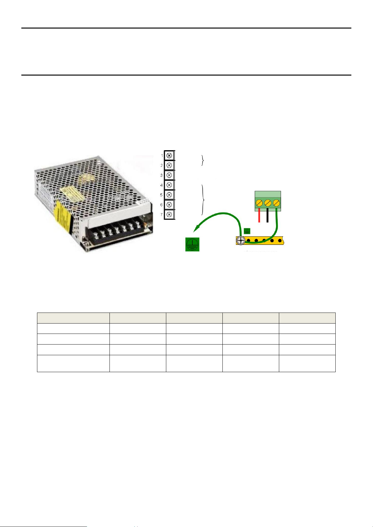
5.1.1 AC Power Supply
To confirm or alter the pre-set operating voltage, open the system front cover, locate the SMPS transformer
on the left side and, if required, change the voltage selector using a screwdriver at the point shown by the
yellow and black label below:
-Ve DC Return
Figure 15. Switched Mode Power Supply (SMPS) Connections
Earth
Note: Mains Earth (Ground) must only be connected to the protective earth (ground) rail, and not to the
SMPS.
Regional power cable wires are coloured in accordance with the following code:
Before making any electrical connections or changes ensure that:
the mains supply isolator switch is in the Off position
the system is set up to operate at the correct voltage
Refer to Chapter 3.1.1 for further information on system electrical specifications and power requirements.
Note 1: Input voltage of less than DC 23.5 V will fail to charge the backup battery, and it will cause battery un-
chargeable warning. Note 2: Field detectors may need their own power supplies if they exceed 15 W per
channel to a combined total of 40 W. Refer to the 5.2.6 mA Input Module Connections.
Table 5. Regional Power Cable Colours
24
 Loading...