

Page 1

Thor™ VX9
Vehicle-Mount Computer
Microsoft®Windows®Embedded Standard Operating System
Microsoft®Windows®7 Professional Operating System
Microsoft®Windows®XP®Professional Operating System
Reference Guide
Page 2

Disclaimer
Honeywell International Inc. (“HII”) reserves the right to make changes in specifications and other information contained in this
document without prior notice, and the reader should in all cases consult HII to determine whether any such changes have
been made. The information in this publication does not represent a commitment on the part of HII.
HII shall not be liable for technical or editorial errors or omissions contained herein; nor for incidental or consequential damages
resulting from the furnishing, performance, or use of this material.
This document contains proprietary information that is protected by copyright. All rights are reserved. No part of this document
may be photocopied, reproduced, or translated into another language without the prior written consent of HII.
© 2009-2012 Honeywell International Inc. All rights reserved.
Web Address: www.honeywellaidc.com
RFTerm is a trademark or registered trademark of EMS Technologies, Inc. in the United States and/or other countries.
Microsoft®Windows, ActiveSync®, MSN, Outlook®, Windows Mobile®, the Windows logo, and Windows Media are
registered trademarks or trademarks of Microsoft Corporation.
Intel®, Atom™, Core™, Celeron®and Pentium®are trademarks or registered trademarks of Intel Corporation or its
subsidiaries in the United States and other countries.
Summit Data Communications, the Laird Technologies Logo, the Summit logo, and "Connected. No Matter What" are
trademarks of Laird Technologies, Inc.
Atheros®and the Atheros logo are registered trademarks of Atheros Communications, Inc.
Broadcom®and the Broadcom logo are registered trademarks of Broadcom Corporation.
The Bluetooth®word mark and logos are owned by the Bluetooth SIG, Inc.
Symbol®is a registered trademark of Symbol Technologies. MOTOROLA, MOTO, MOTOROLA SOLUTIONS and the
Stylized M Logo are trademarks or registered trademarks of Motorola Trademark Holdings, LLC and are used under license.
RAM®and RAM Mount™ are both trademarks of National Products Inc., 1205 S. Orr Street, Seattle, WA 98108.
Freefloat, Freefloat Wlinq and Freefloat Access*One are trademarks of Freefloat, Mölndalsvägen 30B, SE-412 63Gothenburg,
Sweden.
Verizon®is a registered trademark of Verizon Trademark Services LLC.
T-MOBILE®is a registered trademark of Deutsche Telekom AG.
AT&T®is a registered trademark of AT&T Intellectual Property.
Option®and GlobeTrotter®are registered trademarks of Option NV.
Acrobat®Reader © 2012with express permission from Adobe Systems Incorporated.
Other product names or marks mentioned in this document may be trademarks or registered trademarks of other companies
and are the property of their respective owners.
Patents
For patent information, please refer to www.honeywellaidc.com/patents.
Limited Warranty
Refer to www.honeywellaidc.com/warranty_information for your product’s warranty information.
Page 3

Table of Contents
Chapter 1: Introduction 1-1
Overview 1-1
Microsoft Windows License Agreement (First Boot) 1-1
Quick Start 1-2
Components 1-3
Connector Panel 1-3
Buttons and LEDs 1-4
Inside the Thor VX9 1-5
LED Indications 1-6
Power LED 1-6
UPS Mode LED 1-6
COM Port LEDs 1-6
Data Entry 1-7
Keyboard Data Entry 1-7
Bar Code Data Entry 1-7
Touch Screen Entry 1-7
Soft Keyboard Entry 1-8
Chapter 2: Hardware 2-1
Hardware Configuration 2-1
Power Input 2-1
Uninterruptible Power Supply 2-1
Backup Battery 2-1
PCMCIA Slots 2-1
Power Management 2-1
Physical Controls 2-2
Power Button 2-2
Display Brightness Buttons 2-3
External Connectors 2-4
Serial Connector – COM1 2-5
Pinout 2-5
Serial Connector – COM2 2-6
Pinout 2-6
Keyboard/Mouse Connector 2-7
Pinout 2-7
PS/2 Keyboard/Mouse Dongle Cable 2-8
D9 Male Connector 2-9
Pinout 2-9
i
Page 4

PS/2 Keyboard Connector 2-10
Pinout 2-10
PS/2 Mouse 2-11
Pinout 2-11
RJ45 Connector 2-12
Pinout 2-12
Multipurpose Connector 2-13
Pinout 2-13
Multipurpose Dongle Cables 2-14
D15 Female Connector 2-15
Pinout 2-15
USB Connector 2-16
Pinout 2-16
Serial Connector - COM4 2-17
Pinout 2-17
Audio and Microphone Connectors 2-18
Antenna Connectors 2-18
Power Supply Connector 2-19
Pinout 2-19
Keyboards 2-20
95-key Keyboard 2-20
60-key Keyboard 2-21
95-key QWERTY Keyboard with Pointing Device 2-22
Key Maps 2-22
NumLock 2-22
CapsLock and Scroll Lock 2-22
Keyboard Backlight 2-23
60-key QWERTY Keyboard 2-24
Key Maps 2-24
Unused Key Functions 2-24
NumLock 2-24
Keyboard Backlight 2-25
Control Keys 2-25
Keyboard LEDs 2-26
CAPS LED 2-26
Secondary Keys LED 2-27
IBM 3270 Keypad Overlay 2-28
IBM 5250 Keypad Overlay 2-28
General Windows Keyboard Shortcuts 2-29
PS/2 Keyboard/Mouse 2-30
ii
Page 5

Virtual Keyboard 2-30
Display 2-32
Cleaning the Display 2-32
Touch Screen 2-32
PCMCIA Slots 2-33
Install PCMCIA Cards 2-33
PCMCIA Pinout 2-34
Power Supply 2-35
Vehicle DC Connection 2-36
Screen Blanking 2-38
Uninterruptible Power Supply Battery Pack 2-39
External Power Supply 2-39
CMOS Battery 2-39
Hardware Problems 2-40
Power Source 2-40
Keyboard 1-7
Display / Touch Screen 2-41
Hard Disk Drive 2-41
Memory Conflicts 2-41
Optional Devices 2-42
Chapter 3: Software 3-1
Introduction 3-1
Operating System 3-1
BIOS Setup 3-2
Accessing the BIOS Setup 3-3
AMI BIOS 3-3
Phoenix BIOS 3-3
Identifying Drives in the Thor VX9 3-3
AMI BIOS 3-3
Phoenix BIOS 3-3
Integrated Devices 3-4
AMI BIOS 3-4
Phoenix BIOS 3-4
Boot Priority 3-5
AMI BIOS 3-5
Phoenix BIOS 3-5
PXE - Pre Boot Execution 3-5
AMI BIOS 3-5
Phoenix BIOS 3-5
iii
Page 6

Exit BIOS Configuration 3-6
AMI BIOS 3-6
Phoenix BIOS 3-6
VMT Keyboard Backlighting 3-7
Microsoft Windows Setup and Configuration 3-8
Microsoft Windows License Agreement (First Boot) 3-8
Drive C Directory Structure 3-8
Software Loaded on Drive C 3-9
Thor VX9 Configuration Options 3-10
Date and Time 3-10
Power Management 3-10
Speaker Volume 3-10
Connect Bluetooth Devices 3-10
Restart/Shutdown 3-11
Soft Keyboard 3-11
Calibrate Touch Screen 3-11
Touch Screen 3-12
Calibrating the Touch Screen 3-12
Disabling the Touch Screen 3-12
Network Configuration 3-12
802.11 Wireless Radios 3-12
Ethernet Connector 3-12
WWAN 3-12
Bluetooth 3-12
VMT Manager 3-13
Main Tab 3-13
General Settings Tab 3-14
UPS Tab 3-16
Display Backlight Tab 3-17
Advanced Tab 3-18
Wedge 3-19
Configuration 3-19
Loading an Operating System on the Thor VX9 3-21
The Thor VX9 Recovery DVD 3-22
DVD Part numbers 3-22
Thor VX9 Recovery DVD 3-22
Launching the RS2 Wizard 3-22
Using the RS2 Wizard 3-23
The Thor VX9 Drivers CD-ROM 3-24
Startup Problems 3-25
iv
Page 7

Bypassing Microsoft Windows Startup 3-25
Verifying Boot Order 3-25
Setting System Time and Date 3-26
Chapter 4: Wireless Network Configuration 4-1
Introduction 4-1
Summit Wireless Network Configuration 4-2
Important Notes 4-2
Summit Client Utility 4-3
Help 4-3
Summit Tray Icon 4-4
Wireless Zero Config Utility 4-5
How To: Use the Wireless Zero Config Utility 4-5
How to: Switch Control to SCU 4-5
Main Tab 4-6
Admin Login 4-7
Profile Tab 4-8
Buttons 4-9
Profile Parameters 4-10
Status Tab 4-12
Diags Tab 4-13
Global Tab 4-14
Custom Parameter Option 4-15
Global Parameters 4-16
Logon Options 4-20
Single Signon 4-21
Pre-Logon Connection 4-21
Sign-On vs. Stored Credentials 4-22
How to: Use Stored Credentials 4-22
How to: Use Sign On Screen 4-23
How to: Use Windows Username and Password 4-23
Windows Certificate Store vs. Certs Path 4-24
User Certificates 4-24
Root CA Certificates 4-24
How To: Use the Certs Path 4-24
How To: Use Windows Certificate Store 4-24
Configuring the Profile 4-26
No Security 4-27
WEP 4-28
LEAP 4-30
v
Page 8

PEAP/MSCHAP 4-32
PEAP/GTC 4-35
WPA/LEAP 4-38
EAP-FAST 4-40
EAP-TLS 4-42
WPA PSK 4-45
Certificates 4-46
Generating a Root CA Certificate 4-47
Installing a Root CA Certificate 4-51
Generating a User Certificate 4-53
Exporting a User Certificate 4-56
Installing a User Certificate 4-58
Atheros Client Utility - 802.11a/b/g Radio 4-60
Wireless Zero Config 4-60
Using the ACU 4-61
No Security 4-62
WEP 4-63
LEAP 4-65
WPA-PSK 4-67
PEAP/MS-CHAP 4-68
PEAP-GTC 4-70
EAP-TLS 4-72
WPA LEAP 4-74
EAP-FAST 4-76
Broadcom Wireless Utility - 802.11b/g Radio 4-79
Wireless Zero Config 4-79
Using the BWU 4-79
No Security 4-80
WEP 4-81
LEAP 4-82
WPA-PSK 4-83
PEAP/MS-CHAP 4-84
PEAP-GTC 4-85
EAP-TLS 4-86
WPA LEAP 4-88
EAP-FAST 4-89
Certificates 4-90
Bluetooth 4-92
8650 Bluetooth Ring Scanner/Imager 4-92
Devices Tab 4-92
vi
Page 9

Options Tab 4-94
COM Ports Tab 4-95
Hardware Tab 4-96
SIM card installation 4-97
Requirements 4-97
Installation 4-97
Option GlobeTrotter Connect 4-99
SIM Card PIN 4-99
Using Option GlobeTrotter Connect 4-99
OneClick Internet 4-101
Preparing for Initial Use on the Thor VX9 4-101
Install SIM Card 4-101
Load Firmware 4-101
Activation 4-101
Using OneClick Internet 4-104
Connection Management 4-104
Menu Buttons 4-105
Radio Button 4-105
StatisticsButton 4-105
Update Button 4-105
Help Button 4-105
Settings Button 4-106
Profile Tab 4-107
Buttons 4-108
Parameters 4-108
Network Tab 4-109
Network with SIM Card 4-109
CDMA Network 4-111
History Tab 4-112
PIN Tab 4-112
Activate/Deactivate PIN 4-112
Change PIN 4-113
Info Tab 4-114
Firmware Tab 4-115
Activation on CDMA 4-116
General Tab 4-117
Application Tab 4-118
Application Buttons 4-119
SMS 4-119
Web Browser 4-119
vii
Page 10

Email 4-119
GPS 4-119
About 4-120
System Requirements 4-120
Supported Languages 4-120
Installing or Upgrading OneClick Internet 4-120
Installation 4-121
OneClick Internet Connection Manager 4-124
Connection Management 4-124
Information Buttons 4-125
Chapter 5: Key Maps 5-1
95-key Keypad with Pointing Device 5-1
Key Map 101-Key Equivalencies 5-1
60-key Standard Keypad 5-2
60 Key KeyMap 101-Key Equivalencies 5-2
IBM Terminal Emulation 5-7
IBM 3270 Keypad Overlay 5-7
IBM 5250 Keypad Overlay 5-8
Chapter 6: Technical Specifications 6-1
Physical Specifications 6-1
Environmental Specifications 6-2
Display Specifications 6-2
Operating System 6-2
Radio Options 6-3
Chapter 7: Technical Assistance 7-1
viii
Page 11

Chapter 1: Introduction
Overview
The Thor VX9 Vehicle-Mount Computer (VMT) is a rugged, vehiclemounted, PC (Personal Computer) equipped with a Microsoft
®
Windows®operating system. The Thor VX9 is capable of wireless data
communications from a fork-lift truck or any properly configured
vehicle. The unit uses a PCMCIA radio (spread spectrum 2.4GHz) for
wireless data communications.
The Thor VX9 is a tablet-style computer and features a color display.
The touch-screen display supports graphic features and Microsoft
Windows icons that the Windows operating system supports. An
illuminated keyboard is available to facilitate use in dimly lit areas.
The Thor VX9 provides the power and functionality of a desktop
computer in a vehicle-mounted unit, with a wide range of options.
For details on available RAM Mount™ options see the Thor VX9 Vehicle Mounting Reference Guide.
The Thor VX9 is available with the following operating systems:
l Windows
l Windows
l Windows
l Windows
®
7 Professional
®
XP Professional
®
Embedded Standard
®
XP Embedded
The Thor VX9 can support only one operating system at a time. Information in this guide includes instruction for all operating
systems. Differences are highlighted as follows:
Windows® 7 Professional
Windows® Embedded Standard
Windows® XP Embedded
Windows® XP Professional
Microsoft Windows License Agreement (First Boot)
If your Thor VX9 is shipped with a Microsoft Windows operating system pre-installed, it may be necessary to
complete the Windows licensing/registration screens when starting the Thor VX9 for the first time. To complete this
information, you may need the Microsoft Windows software/product key that was included with the Thor VX9.
Please refer to Microsoft Windows License Agreement (First Boot) for instruction.
1-1
Page 12

Quick Start
This section’s instructions are based on the assumption that your new system is pre-configured and requires only accessory
installation (e.g. antenna, external keyboard and/or bar code scanner) and a power source.
In general, the sequence of events to prepare the Thor VX9 for use is:
1. Install Vehicle Mounting Bracket (and keyboard mounting bracket) on vehicle.
2. Secure Thor VX9 in Mounting Bracket Assembly.
3. Connect power cable to the Thor VX9. Route the power cable to a DC/DC converter then to the vehicle battery.
4. An optional screen blanking box may also be connected to the Thor VX9.
5. Connect accessories to Thor VX9, e.g. scanner, keyboard.
6. Secure all cables to the Thor VX9 with the Strain Relief Cable Clamps.
7. Turn the Thor VX9 on.
The Thor VX9 and its keyboard should be mounted in an area in the vehicle where it:
l Does not obstruct the vehicle driver’s vision or safe vehicle operation.
l Can be easily accessed by anyone seated in the driver’s seat.
1-2
Page 13

Components
Connector Panel
Position Function
1 Connection for external antenna
2 Power supply
3 COM2 port
4 COM1 port
5 Keyboard/mouse
6 RJ-45 10/100 LAN
7 1 х USB 2.0
8 Multipurpose Connection (provides USB, COM4 or both with optional cable)
9 Audio Out 3.5 mm
10 Mic In 3.5 mm
1-3
Page 14

Buttons and LEDs
Position Function
1 Power Button
2 Power LED
3 Decrease Display Brightness
4 UPS LED
5 Increase Display Brightness
6 COM2 LED - Yellow light indicates +12V from pin 9
7 COM1 LED - Green light indicates +5V from pin 9
1-4
Page 15

Inside the Thor VX9
1. Torx 20 Screws
2. PCMCIA Card Slots,
optional
3. PCMCIA Card Ejection
Buttons
1-5
Page 16

LED Indications
Power LED
The Power LED is located beside the power button.
Function Power LED
Off and not powered Off (no light)
Off but powered Green flash very slow
Operating normally Green on
Suspend Green flashing slow
Black-out Screen Green flashing fast
Over voltage shutdown Red on
Over temperature Red flashing
UPS Mode LED
The UPS Mode LED is located between the Brightness control buttons.
Function UPS Mode LED
UPS battery powered Green flashing fast
UPS battery charging Green on or flashing slow
UPS battery charged Off (no light)
COM Port LEDs
The COM Port LEDs are located next to the COM port connectors.
Function Hard Drive LED
COM1 has +5V on pin 9 Green
COM2 has +12V on pin 9 Amber
No power on pin 9 Off (dark)
1-6
Page 17

Data Entry
You can enter data into the Thor VX9 through several different methods. A tethered scanner connected to the COM1 serial port
or a Bluetooth scanner provides bar code data entry, the serial ports are used to input/output data, keyboards provide manual
entry and the touch screen also provides manual entry (simulating a desktop PC’s mouse).
Keyboard Data Entry
Refer to Key Maps for 101-key keyboard equivalent keypresses.
The keyboard is used to manually input data that is not collected otherwise. Almost any function that a full sized computer
keyboard can provide is duplicated on the VMT keyboard but it may take a few more keystrokes to accomplish a keyed task.
When using the 60-key keyboard almost every key has two or three different functions. The primary alpha or numeric character
is printed on the key.
For example, when the 2ndkey is selected pressing the desired second-function key produces the 2ndcharacter i.e. 2nd+ F1
toggles the CAPS Lock function. The specific 2ndcharacter is printed above the corresponding key.
Bar Code Data Entry
The Thor VX9 supports an accessory bar code label reading device. Keyboard data entries can be mixed with bar code data
entries. Any scanner that decodes the bar code internally and outputs an RS-232 data stream may be used. COM port 1 is
designed to be used with a hand held tethered bar code scanner. Also, a Bluetooth bar code scanner can be used to enter bar
code data into the Thor VX9.
COM1 must be set to +5V on pin 9 when using a tethered serial scanner. See VMT Manager.
Touch Screen Entry
Note: The touch screen should be calibrated before initial use. See Touch Screen Calibration.
Note: Always use the point of the stylus for tapping or making strokes on the display. Never use an actual pen, pencil or
sharp object to write on the touch screen.
The touch screen input performs the same function as the mouse that is used to point to and click elements on a desk top
computer. A stylus is used in the same manner as a mouse – single-tap or double-tap to select menu options, drag the stylus
across text to select, hold the stylus down to activate slider bars, etcetera. Right-click is generated by tapping the mouse icon
in the system tray. After tapping, the mouse icon highlights the right button of the icon in red. The next touch screen tap is
treated as a right-click. The mouse icon then returns to the left button highlighted in red so subsequent taps are treated as left
clicks.
Hold the stylus as if it were a pen or pencil. Touch an element on the screen with the tip of the stylus then remove the stylus
from the screen. The touch screen responds to an actuation force (touch) of up to 4 oz. of pressure.
The touch screen can be used in conjunction with the keyboard and scanner.
l Touch the stylus to the field of the data entry form to receive the next data feed.
l The cursor begins to flash in the field.
l The unit is ready to accept data from either the keyboard, integrated scanner or a device connected to a serial port.
Note: The touch screen may be disabled. Please refer to Disabling the Touch Screen.
1-7
Page 18

Soft Keyboard Entry
The optional software keyboard provides a virtual keyboard on the touch screen. The soft keyboard is orderable in several
configurations.
Note: When the virtual keyboard is displayed, the physical keyboard is still active, if attached. Therefore it is possible to
input data from both keyboards.
1-8
Page 19

Chapter 2: Hardware
Hardware Configuration
The Thor VX9 is available in many configurations. Please refer to Technical Specifications for available options.
Note: Using the VMT Manager, Pin 9 of COM1 may be configured to provide 5 volts DC to power a bar code scanner or RI
for serial transfer.
Power Input
Vehicle power input for the Thor VX9 is determined by the DC/DC power supply selected. The DC/DC power supply accepts
input in the stated range and provides a conditioned 12V DC output for the Thor VX9.
If DC power is not available – for example, in an office environment – an optional external Universal Input Power Supply can be
used to convert AC wall power to an appropriate DC level. See Power Supply.
Uninterruptible Power Supply
A DC uninterruptible power supply (UPS) battery is included to maintain power to the Thor VX9 for a minimum of 15 minutes
when vehicle power is not available (such as when a vehicle battery is being swapped). The UPS is configured via the VMT
Manager.
Backup Battery
The Thor VX9 has a permanent lithium battery installed to maintain time, date and BIOS setup information. The backup battery
is not user serviceable and should last five years with normal use before it requires replacement.
Note: This battery should only be changed by authorized service personnel.
PCMCIA Slots
Microsoft Windows Plug and Play operating system controls the PCMCIA cards. These cards are hot swappable per the
CardBus/PCMCIA specifications. PCMCIAslots are optional.
Power Management
The Thor VX9 uses Microsoft Windows Power Management. The Thor VX9 has two operating modes: Normal and Standby.
In Normal operating mode all systems are powered up and the video display is on. The RS-232 ports, any installed PCMCIA
cards are active. However, Microsoft Windows also allows the display and hard disks to be shut down in normal mode to
conserve energy.
The Standby mode shuts down many devices such as the display and hard drives. For complete details on the standby mode,
please refer to the Microsoft Help &Support (Start > Help and Support).
2-1
Page 20

Physical Controls
Power Button
The power (on/off) button is a push button switch located on the bottom of the Thor VX9. The switch is a momentary switch. If
the Thor VX9 is Off, pressing the power switch turns the Thor VX9 On. If the Thor VX9 is On, Windows determines the results
of a power button press. For example, the Thor VX9 may be configured to:
l Shut down
l Hibernate
l Ignore the power button press
l Ask user to choose.
Power button behavior is configured by selecting:
Start > Control Panel > Power Options > Choose what the Power buttons do (Classic view)
Start > Control Panel > Hardware and Sound > Power Options > Choose what the Power buttons do (Cat-
egory view)
Start > Control Panel > Power Options > Advanced (Classic view)
Start > Control Panel > Performance and Maintenance > Power Options > Advanced (Category view)
Pressing and holding the power switch for several seconds forces a shutdown.
Note: Always turn the computer off prior to removing power cables.
The Thor VX9 is designed for a controlled shutdown when using the power button. A controlled shutdown first closes any open
programs, and then shuts down the Windows operating system. DO NOT remove power from the Thor VX9 without shutting
down the Thor VX9.
The Thor VX9 shutdown may be initiated in any of the following ways:
l Selecting the Shut Down option from the Windows Start Menu.
l Selecting the Shut Down option from the Windows Task Manager. The Windows Task Manager is displayed by
pressing Ctrl-Alt-Del.
l Momentarily pressing and releasing the power button. The Thor VX9 behavior when the power button is pressed can be
configured in the Windows Control Panel.
2-2
Page 21
l Pressing and holding the power button for approximately five seconds. Any open programs and the Windows operating
system are shut down before power off. Note that this option must be used to shut down when the operating system is
not responding.
l The VMT Manager can be configured so that an extended touch on the touch screen initiates the shut down process.
For more information on the Windows shutdown process, please refer to Help and Support on the Windows Start menu or
commercially available Windows guides.
Display Brightness Buttons
Screen brightness is adjusted using the buttons on the bottom of the Thor VX9.
The screen’s background lighting can be turned off by holding both buttons simultaneously.
Background lighting is restored by pushing one of the buttons or by touching the screen
2-3
Page 22

External Connectors
Most external connectors for the Thor VX9 are located on the bottom of the unit.
l The Keyboard/Mouse connector accepts a Honeywell VMT keyboard or a dongle cable for a PS/2 keyboard and mouse.
l COM 1 connects to a serial bar code scanner cable.
l COM 2 connects to a serial printer or PC with the appropriate cables.
l The USB connector is a standard USB type A host connector.
l The Ethernet connector is a standard RJ45 10/100 Ethernet connector.
l The multipurpose connector is a D15 connector that can provide a USB port, D9 serial RS-232 (COM4) port or both
depending on the accessory cable attached to the connector.
l Audio connector is a 3.5 mm jack for audio out, i.e. a headset.
l Microphone connector is a 3.5mm jack for audio in, i.e. a microphone.
l External Bluetooth antenna connector.
Note: Pin 9 of the COM 1 can be switched between +5V and RI to change between a bar code scanner and a serial port
printer or PC cable. See VMT Manager.
Other external connectors are located as follows:
l 802.11 antenna connectors are located on the top of the Thor VX9. One of these connectors may also be used by the
WWAN radio.
2-4
Page 23

Serial Connector – COM1
COM1 provides +5v on pin 9 when enabled. Only COM1 should be used to connect an external scanner to the
Thor VX9.
The serial connector, with a (1) label, (configured as COM1) is industry-standard RS-232. The connector includes a PC/AT
standard 9–pin “D” male connector. The VMT Manager controls the function of pin 9. Pin 9 is capable of supplying +5 VDC for
an external bar code scanner. Refer to VMT Manager for more information on configuring pin 9.
Pinout
Pin Signal Description
1 DCD Data Carrier Detect – Input
2 RXD Receive Data – Input
3 TXD Transmit Data – Output
4 DTR Data Terminal Ready – Output
5 GND Signal/Power Ground
6 DSR Data Set Ready – Input
7 RTS Request to Send – Output
8 CTS Clear to Send – Input
+5VDC
9
or
RI
Note: Pin 9 of the COM port can be switched between +5V and RI. See VMT Manager.
Ring Indicator – Input (Default)
or
Bar code Scanner Power – 400mA max
2-5
Page 24

Serial Connector – COM2
COM2 provides +12v on pin 9 when enabled.
Do not connect a serial bar code scanner to COM2 as this may damage the scanner, the Thor VX9 or both.
The COM2 serial connector is an industry-standard RS-232 9-pin “D” connector. The connector and its pin assignments are
shown below.
Pinout
Pin Signal Description
1 DCD Data Carrier Detect – Input
2 RXD Receive Data – Input
3 TXD Transmit Data – Output
4 DTR Data Terminal Ready – Output
5 GND Signal/Power Ground
6 DSR Data Set Ready – Input
7 RTS Request to Send – Output
8 CTS Clear to Send – Input
Ring Indicator – Input (default)
9RIor
+12VDC
Note: Pin 9 of the COM port can be switched between +12V and RI. See VMT Manager.
or
Power – 400mA max
2-6
Page 25

Keyboard/Mouse Connector
The Thor VX9 external keyboard connector accepts:
l A Honeywell VMT keyboard with integrated pointing device
l A Honeywell VMT keyboard without integrated pointing device
l A dongle cable providing PS/2 connections for a standard PS/2 keyboard and mouse.
Pinout
Pin Signal Description
1 – Not Connected
2 MS_DATA Mouse Data
3 MS_CLK Mouse Clock
4 VCC Keyboard Power, 5V
5 GND System Ground
6 +12VKB Keyboard Power, 12V
7 KB_DATA Keyboard Data
8 KB_CLK Keyboard Clock
9 – Not Connected
2-7
Page 26

PS/2 Keyboard/Mouse Dongle Cable
The PS/2 keyboard/mouse dongle cable allows a standard PS/2 keyboard and/or mouse to be attached to the Thor VX9. The
PS/2 connectors on the dongle cable are labeled/color coded for standard keyboard and mouse PS/2 connections.
1. D9 Connector
2. PS/2 Keyboard (purple)
Connector
3. PS/2 Mouse (green)
Connector
2-8
Page 27

D9 Male Connector
Pinout
Pin Signal Description
1 – Not Connected
2 MS_DATA Mouse Data
3 MS_CLK Mouse Clock
4 VCC Keyboard Power, 5V
5 GND System Ground
6 +12VKB Keyboard Power, 12V
7 KB_DATA Keyboard Data
8 KB_CLK Keyboard Clock
9 – Not Connected
2-9
Page 28

PS/2 Keyboard Connector
Pinout
Pin Signal Description
1 KBDAT_A Keyboard Data
2 – Not Connected
3 DGND System Ground
4 KBD_PWR Keyboard Power, 5V
5 KBCLK_A Keyboard Clock
6 – Not Connected
Shell CGND Chassis Ground
2-10
Page 29

PS/2 Mouse
Pinout
Pin Signal Description
1 MSDAT_A Mouse Data
2 – Not Connected
3 DGND System Ground
4 KBD_PWR Keyboard Power, 5V
5 MSCLK_A Mouse Clock
6 – Not Connected
Shell CGND Chassis Ground
2-11
Page 30

RJ45 Connector
Pinout
Pin Signal Description
1 TXP Transmit +
2 TXN Transmit –
3 RXP Receive +
4 – Not Connected
5 – Not Connected
6 RXN Receive –
7 – Not Connected
8 – Not Connected
2-12
Page 31

Multipurpose Connector
The Thor VX9 Ethernet/USB connector accepts a dongle cable that provides a USB port, an Ethernet port or both. The
connector is shown below.
Pinout
Pin Signal Description
1 VCC 5 +5V power
2 RXD Receive Data, COM4
3 TXD Transmit Data, COM4
4 – Not Connected
5 +12V 12V power supply
6 USB + USB Data+
7 USB USB Data
8 GND Ground
9 – Not Connected
10 GND Ground
11 GND Ground
12 RTS COM4 Handshake
13 CTS COM4 Handshake
14 – Not Connected
15 – Not Connected
2-13
Page 32

Multipurpose Dongle Cables
1. To D15 Connector on
Thor VX9
2. D9 Serial Connector
(COM4)
3. USB Connector
2-14
Page 33

D15 Female Connector
Pinout
Pin Signal Description
Pin Signal Description
1 VCC 5 +5V power
2 RXD Receive Data, COM4
3 TXD Transmit Data, COM4
4 – Not Connected
5 +12V 12V power supply
6 USB + USB Data+
7 USB USB Data
8 GND Ground
9 – Not Connected
10 GND Ground
11 GND Ground
12 RTS COM4 Handshake
13 CTS COM4 Handshake
14 – Not Connected
15 – Not Connected
2-15
Page 34

USB Connector
Pinout
Pin Signal Description
1 VCC +5V USB Power
2 USB2N_A USD D –
3 USB2P_A USB D +
4 DGND USB Power Return
2-16
Page 35

Serial Connector - COM4
COM4 provides +12v on pin 9 when enabled.
Do not connect a serial bar code scanner to COM4 as this may damage the scanner, the Thor VX9 or both.
The COM4 serial connector is an industry-standard RS-232 9-pin “D” connector. The connector and its pin assignments are
shown below.
Pinout
Pin Signal Description
1 DCD Data Carrier Detect – Input
2 RXD Receive Data – Input
3 TXD Transmit Data – Output
4 DTR Data Terminal Ready – Output
5 GND Signal/Power Ground
6 DSR Data Set Ready – Input
7 RTS Request to Send – Output
8 CTS Clear to Send – Input
Ring Indicator – Input (default)
9RIor
+12VDC
Note: Pin 9 of the COM port can be switched between +12V and RI. See VMT Manager.
or
Power – 400mA max
2-17
Page 36

Audio and Microphone Connectors
Audio Out is a standard 3.5mm earphone outlet.
Microphone In is a standard 3.5mm microphone inlet.
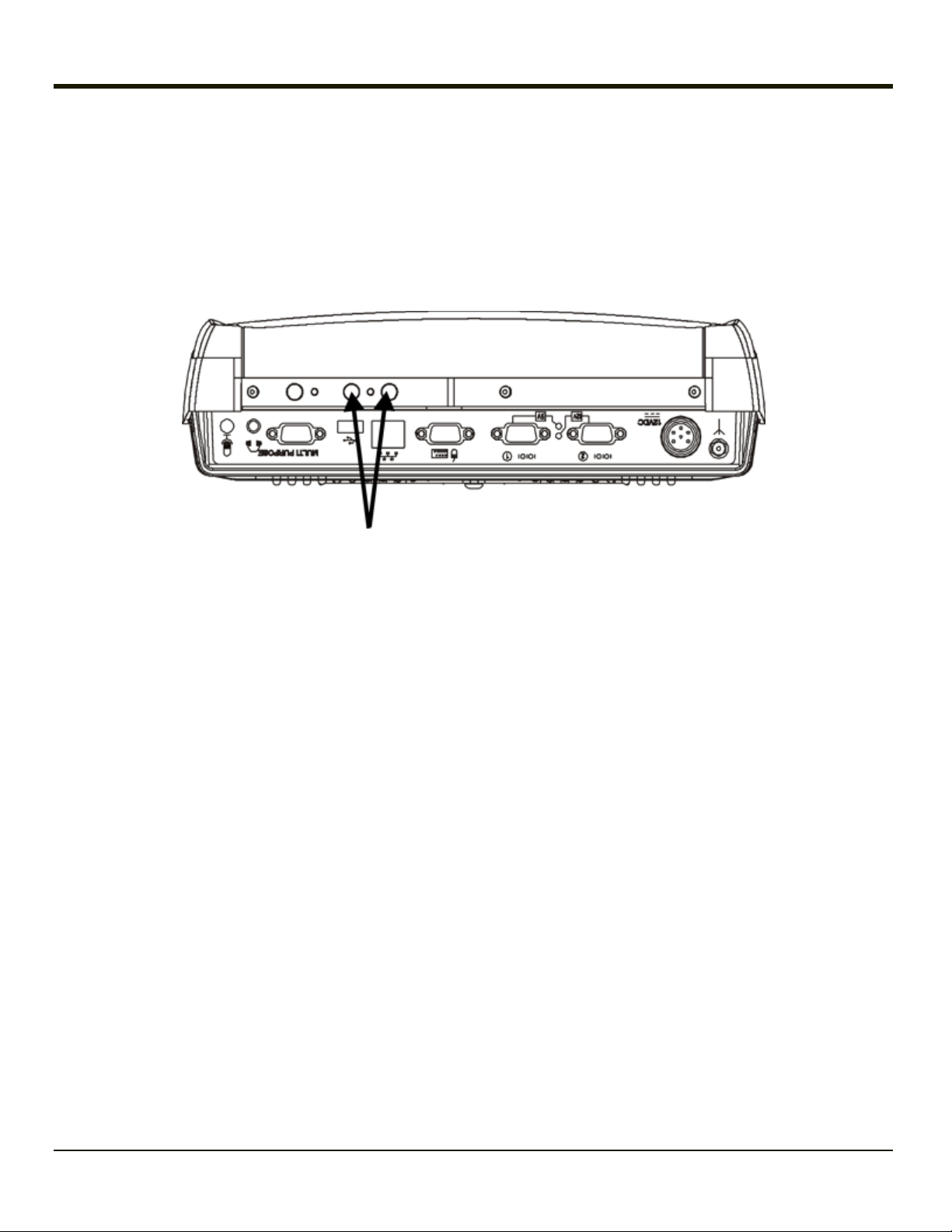
Antenna Connectors
The Thor VX9 has up to three antenna connectors, depending on the options ordered.
Two antenna connectors are located on the top of the Thor VX9. If the Thor VX9 contains an 802.11 radio, these connectors
provide diversity antennas for the radio. The connectors can also be used to connect a remote antenna.
One antenna connector is located on the bottom of the Thor VX9. This antenna connector is for the Bluetooth antenna.
If a Thor VX9 is ordered with WWAN, one of the antenna locations can be used to connect the WWAN antenna. It may be
necessary to use to use one of the top connectors. If one of the top antenna connectors is used for a WWAN antenna, the other
can still be used by the 802.11 radio although the 802.11 radio would no longer use antenna diversity.
2-18
Page 37

Power Supply Connector
Power is supplied to the Thor VX9 through the power connector. Additionally this assembly provides for input for the screen
blanking feature, if desired.
The Thor VX9 must be connected to either:
l an approved AC to DC converter, or
l a DC to DC power supply delivering conditioned DC power.
Pinout
Pin Signal
1 DC Positive (+)
2 Not connected
3 DC Negative (–)
4 Not connected
5 Screen blanking box (optional)
6 Screen blanking box (optional)
2-19
Page 38

Keyboards
The following keyboard options are available for the Thor VX9:
l VMT 95-key QWERTY keyboard with integrated pointing device – a customized rugged keyboard connected to the Thor
VX9 via an adapter cable.
l VMT 60-key QWERTY keyboard – a customized rugged keyboard connected to the Thor VX9 via an adapter cable.
l A standard PS/2 keyboard via an adapter cable attached to the Keyboard port on the Thor VX9. The adapter cable also
provides a connector for a PS/2 mouse.
l A software keyboard, or virtual keyboard, can be displayed on the touch screen. The virtual keyboard can be used in
place of, or in addition to, a physical keyboard.
95-key Keyboard
This keyboard contains an integrated pointing device. An adapter cable is required to attach this keyboard to the Thor VX9.
2-20
1. To adapter cable
2. To 90-key keyboard cable
3. To VX9 keyboard connector
Page 39

60-key Keyboard
An adapter cable is required to attach this keyboard to the Thor VX9.
1. To adapter cable
2. To 60-key keyboard cable
3. To VX9 keyboard connector
2-21
Page 40

95-key QWERTY Keyboard with Pointing Device
Designed for ease of use with Windows operating systems, the 95-key keyboard with pointing device connects via a cable to
the keyboard port on the Thor VX9. Additional Windows keys (the Windows logo key and the Application key) and an integrated
pointing device are provided for ease of use with Windows operating systems.
Key Maps
The 95-key keyboard supports all 104 keyboard functions (101 keyboard standard plus Windows keys) and includes an
integrated pointing device and left and right mouse buttons. However, because the keyboard only has 95 keys, all functions are
not visible (or printed on the keyboard). Therefore the Thor VX9 keyboard supports what is called hidden keys -- keys that are
accessible but not visible on the keyboard.
As with a standard keyboard, many keys are found in the Alphanumeric section as well as on the Numeric keypad (i.e. the 1
key is found on the numeric keypad and above the alpha characters on standard keyboards). However these keys send
distinctly different scan codes when the keys are pressed. The hidden keys supported by the Thor VX9 are listed in Key Maps.
Note: The 95-key keyboard does not have a 2ndkey function.
NumLock
For the 95-key keyboard, the NumLock key and the numeric keys are backlit green when NumLock is off. When NumLock is
on, the backlight for the NumLock key and the numeric keys is amber.
CapsLock and Scroll Lock
For the 95-key keyboard, the CapsLock key is backlit green when CapsLock is off. When CapsLock is on, the backlight for the
CapsLock key is amber.
The Scroll Lock key is backlit green when Scroll Lock is off. When Scroll Lock is on, the backlight for the Scroll Lock key is
amber.
The default values for CapsLock and Scroll Lock are Off.
2-22
Page 41

Keyboard Backlight
The 95-key keyboard backlights each key with an LED. The keyboard backlight is manually controlled using the
“backlight” key in the upper right hand corner of the keyboard. Pressing the backlight key cycles the keyboard
backlight through the levels of backlight intensity:
l Off
l Maximum intensity
l Medium intensity
l Low intensity.
2-23
Page 42

60-key QWERTY Keyboard
The 60-key keyboard has 101 keyboard functions, including a numeric keyboard pad. Please refer to Key Maps for keypress
combinations.
The 60 key keyboard is also available with overlays designed for use with IBM 3270 and IBM 5250 terminal emulations.
Key Maps
The 60-key keyboard supports all 101 keyboard functions. However, because the keyboard only has 60 keys, all functions are
not visible (or printed on the keyboard). Therefore the Thor VX9 keyboard supports what is called hidden keys -- keys that are
accessible but not visible on the keyboard.
On standard keyboards many keys are found in the Alphanumeric section as well as on the Numeric keypad (i.e. the 1 key is
found on the numeric keypad and above the alpha characters on standard keyboards). However these keys send distinctly
different scan codes when the keys are pressed. The default codes for the Thor VX9 number keys correspond to the numeric
keypad on standard keyboards. In order to duplicate the codes sent when the alphanumeric key is pressed, the hidden
keystroke must be used.
The hidden keys supported by the Thor VX9 are listed in Key Maps.
Unused Key Functions
There are several key functions on the 60-key keyboard that are not used on the Thor VX9. These include:
nd
l 2
l 2
F3 – The Resume/Suspend function is not used as Microsoft Windows controls all power management modes.
nd
F4 and 2ndF5 – The Display Brightness functions are not used as the display brightness is adjusted by the buttons
on the Thor VX9.
nd
l 2
F6 and 2ndF7 – The Contrast functions are not used as the contrast is not adjustable on the TFT display on the
Thor VX9.
nd
l 2
F8 and 2ndF9 – The Volume control keys are not used as volume is adjusted via the Microsoft Windows Volume
icon in the System Tray.
nd
l 2
F10 – Please see below for details on toggling the keyboard backlight.
NumLock
The 60-key keyboard does not have a NumLock indicator or key. NumLock can be toggled On or Off using the 2ndSHIFT F10
keypress sequence. Changes made to the NumLock status persist across a Windows restart.
2-24
Page 43

Keyboard Backlight
The keyboard keys are backlit with LEDs. The backlight is manually controlled using the 2nd+ CTRL + F10 keypress
sequence.
Control Keys
The VMT keyboard has several control keys. Because of the construction of the Thor VX9 and the Microsoft Windows
operating system, many of the Control Keys are not used on the Thor VX9.
The 2ndfunctions of the F4 and F5 keys are not used as the display brightness is adjusted via the buttons on the Thor VX9.
The 2ndfunctions of the F6 and F7 keys are not used as the Thor VX9 has TFT LCD screen with no provision for contrast
adjustments.
The 2ndfunctions of the F8 and F9 keys are not used as the sound volume on the Thor VX9 is controlled with the Sound icon in
the Microsoft Windows System Tray.
The F10 key is used to toggle the backlight as part of the keypress sequence 2nd+ CTRL + F10. This key sequence
immediately toggles the status of the keyboard backlight. Pressing 2nd+ F10 has no effect on the keyboard backlight.
1. Display Brightness Control Keys
(Not used)
2. Display Contrast Control Keys (Not
used)
3. Speaker Volume Control Keys (Not
used)
4. Backlight Control Key (See above)
2-25
Page 44

Keyboard LEDs
The Thor VX9 keyboard has two (2) LED indicators.
1. CapsLock Mode LED
Indicator
2. Secondary Mode LED
Indicator
CAPS LED
This LED indicates the state of the keyboard CapsLock mode. If CapsLock is enabled this LED is illuminated green. When
CapsLock is off, the LED is dark.
Press 2ndthen F1 to toggle CapsLock On and Off.
The default value of CapsLock is “Off”.
2-26
Page 45

Secondary Keys LED
The VMT keyboard is equipped with several secondary keys. These keys are identified by the superscripted text found on the
keyboard keys. The secondary keys are accessible by using two (2) keystrokes: the 2ndkey followed by the superscripted
key.
Once the 2ndstate is enabled (by pressing the 2ndkey) the Secondary Mode LED is illuminated and the 2ndstate is enabled
until another key is pressed. The 2ndkey is toggled on with a 2ndkeypress and then immediately off with another 2ndkeypress.
For example:
Press 2ndand F1 to turn CapsLock on and off.
Press 2ndand ↑ (up arrow) to initiate the PgUp command.
Press 2ndand Q to type the “!” key.
Press 2ndand BkSp to enter the Insert (Ins) mode.
2-27
Page 46

IBM 3270 Keypad Overlay
The 60-key keypad is available with an IBM 3270 overlay designed to allow the user to enter terminal emulator commands
when running RFTerm.
IBM 5250 Keypad Overlay
The 60-key keypad is available with an IBM 5250 overlay designed to allow the user to enter terminal emulator commands
when running RFTerm.
2-28
Page 47

General Windows Keyboard Shortcuts
Use the keyboard shortcuts in the chart below to navigate with any Thor VX9 keyboard. These are standard keyboard
shortcuts for Windows applications.
Press these keys … To …
CTRL + C Copy
CTRL + X Cut
CTRL + V Paste
CTRL + Z Undo
DELETE Delete
SHIFT with any of the arrow keys
Select more than one item in a window or on the desktop, or select text
within a document.
CTRL+A Select all.
ALT+ESC Cycle through items in the order they were opened.
CTRL+ESC Display the Start menu.
ALT+Underlined letter in a menu name Display the corresponding menu.
Underlined letter in a command name on an
open menu
Carry out the corresponding command.
ESC Cancel the current task.
The touch screen provides equivalent functionality to a mouse:
l A touch on the touch screen is equivalent to a left mouse click.
l Many items can be moved by the “drag and drop” method, touching the desired item, moving the stylus across the
screen and releasing the stylus in the desired location.
l A double stylus tap is equivalent to a double-click.
l Right-click is generated by tapping the mouse icon in the system tray. After tapping, the mouse icon highlights the right
button of the icon in red. The next touch screen tap is treated as a right-click. The mouse icon then returns to the left
button highlighted in red so subsequent taps are treated as left clicks.
2-29
Page 48

PS/2 Keyboard/Mouse
A standard PS/2 keyboard and mouse can be attached to the Thor VX9 using the appropriate dongle cable. The dongle cable
attaches to the Thor VX9 and provides two PS/2 connectors, one labeled “Keyboard” and one labeled “Mouse”. Please refer to
documentation provided with the PS/2 keyboard and mouse for more information on their operation.
Virtual Keyboard
The optional software keyboard provides a virtual keyboard on the touch screen. The soft keyboard is available in several
configurations.
Note: When the virtual keyboard is displayed, the physical keyboard is still active, if attached. Therefore it is possible to
input data from both keyboards.
Windows® Embedded Standard
Windows® XP Embedded / Professional
For more information on configuring the virtual keyboard, click on Start > Programs > MountFocus POS > Keyboard
Control Panel.
Windows® 7 Professional
For more information on configuring the soft keyboard, click on the Tools down arrow > Options > Opening on the soft
keyboard or Start > Control Panel > Tablet PC Settings > Other > Go to Input Panel options.
2-30
Page 49

How To: Disable the Soft Keyboard
Windows 7 Professional only.
Open the on-screen Tablet PC Input Panel (see previous figure Soft Keyboard, Typical Configuration). Click the Tools down
arrow > Options > Opening tab. Disable (uncheck) For touch input, show the icon next to the text box. Disable (uncheck) Show
the icon on the taskbar. Disable (uncheck) Use the Input Panel tab. Click OK. The soft keyboard is disabled immediately. The
soft keyboard is not restored on reboot.
How To: Enable the Soft Keyboard
Windows 7 Professional only.
Select Control Panel > Tablet PC Settings > Other. Click the link Go to Input Panel Settings. On the Opening tab, enable
(check) For touch input, show the icon next to the text box. Enable (check) Show the icon on the taskbar. Enable (check) Use
the Input Panel tab. Click OK. The soft keyboard is enabled immediately.
2-31
Page 50

Display
The Thor VX9 Display is capable of supporting SVGA or XGA graphics modes. The display covering is designed to resist
stains. The touch screen allows signature capture and touch input. A display optimized for outdoor viewing is available.
The display supports screen blanking to eliminate driver distraction when the vehicle is in motion. Please see Screen Blanking
Box for details.
Cleaning the Display
Keep fingers and rough or sharp objects away from the display. If the glass becomes soiled or smudged, clean only with a
standard household cleaner such as Windex® without vinegar or use Isopropyl Alcohol. Do not use paper towels or harshchemical-based cleaning fluids since they may result in damage to the glass surface. Use a clean, damp, lint-free cloth. Do not
scrub optical surfaces. If possible, clean only those areas which are soiled. Lint/particulates can be removed with clean,
filtered canned air.
Touch Screen
The touch screen is a Resistive Panel with a scratch resistant finish that can detect touches by a stylus, and translate them
into computer commands. In effect, it simulates a computer mouse. Only Delrin or plastic styluses should be used.
The touch screen is available in standard, hardened and defroster versions.
Note: Always use the point of the stylus for tapping or making strokes on the display. Never use an actual pen, pencil or
sharp object to write on the touch screen.
An extra or replacement stylus may be ordered from Honeywell.
Please refer here for more information, including:
l Calibrating the touch screen
l Disabling the touch screen.
2-32
Page 51

PCMCIA Slots
The Thor VX9 has two optional PCMCIA slots. The PCMCIA slots are stacked on top of each other and can be accessed by
removing the service lid.
1. Torx 20 Screws
2. PCMCIA Card Slots
3. PCMCIA Card Ejection
Buttons
PCMCIA Card Management is handled by Microsoft Windows. The PCMCIA cards are Plug and Play devices and can be “hot
swapped”. For more details, refer to Help and Support on the Windows Start menu or refer to the documentation delivered with
the PCMCIA card.
Install PCMCIA Cards
Equipment Needed: Torx 20 screwdriver
1. Turn the Thor VX9 off and detach the power cable.
2. Loosen the two (2) Torx 20 screws securing the service hatch so the cover can be removed. The screws are a captive
part of the cover and cannot be removed.
3. Partially insert the 2.4GHz Type II PCMCIA Radio into Slot 0 (the upper right slot).
4. Insert the PCMCIA card into the slot.
5. Reattach the service panel and tighten the screws. Exercise care to make sure the antenna cables are not pinched.
6. Re-connect the power cord/cable and turn the Thor VX9 on.
2-33
Page 52

PCMCIA Pinout
Pin Signal Pin Signal Pin Signal
1 GND 24 A5 47 A18
2 D3 25 A4 48 A19
3 D4 26 A3 49 A20
4 D5 27 A2 50 A21
5 D6 28 A1 51 SLOT_VCC
6 D7 29 A0 52 SLOT_VPP
7 -CE1 30 D0 53 A22
8 A10 31 D1 54 A23
9 -OE 32 D2 55 A24
10 A11 33 WP/A_-IOIS16 56 A25
11 A9 34 GND 57 n.c. or VS2#
12 A8 35 12V_RF_POWER 58 RESET
13 A13 36 -CDI 59 -WAIT
14 A14 37 D11 60 -INPACK
15 -WE 38 D12 61 -REG
16 RDY/-IREQ 39 D13 62 BVD2/-SPKR
17 SLOT_VCC 40 D14 63 BDV1/-STSCHG
18 SLOT-VPP 41 D15 64 D8
19 A16 42 -CE2 65 D9
20 A15 43 n.c. or VS1# 66 D10
21 A12 44 -IORD 67 -CD2
22 A7 45 -IOWR 68 GND
23 A6 46 A17
2-34
Page 53

Power Supply
Vehicle power input for the Thor VX9 is dependent on the power supply selected. Availability of power supplies may vary by
region:
VX89A301PSDC9TO36V, Power Supply, DC/DC for 9-36V trucks, 60W
VX89A302PSDC48V, Power Supply, DC/DC for 18-60V trucks, 60W
VX89A303PSDC60TO110V, Power Supply, DC/DC for 50-150V trucks, 60W
Important – A DC to DC power supply is required to provide a conditioned power source to the Thor VX9. The Thor VX9 cannot
be connected to vehicle power without the DC to DC power supply.
If DC power is not available – for example, in an office environment – an optional external AC Power Supply can be used to
convert AC wall power to an appropriate DC level.
Please review the installation cautions and warnings contained in the Thor VX9 Vehicle Mounting Reference Guide.
2-35
Page 54

Vehicle DC Connection
Note: Correct electrical polarity is required for safe and proper installation. Connecting the cable to the Thor VX9 with the
polarity reversed will cause the Thor VX9’s fuse to be blown. See the following figures for wire color-coding specifics.
Power Cable Routing without Screen Blanking
2-36
Page 55

Power Cable Routing with Screen Blanking Box
2-37
Page 56

Connection with Relay/Mechanical Switch for Screen Blanking
In the example below, a user supplied relay/switch that supplies a mechanical electrically conductive connection on vehicle
motion is used.
Screen Blanking
When properly configured and wired as shown above with either a screen blanking box or mechanical switch, the Thor VX9
screen blanking blanks the when the vehicle is in motion. The screen blanking behavior can be configured using the VMT
Manager.
2-38
Page 57

Uninterruptible Power Supply Battery Pack
An Uninterruptible Power Supply (UPS) is built into the Thor VX9 to provide power for short periods of time when vehicle power
is unavailable (such as when vehicle batteries are swapped). The UPS, when enabled, can be used to power the Thor VX9 for
a specified period of time before shutdown.
Configuration of the UPS is handled via the VMT Manager option in the Control Panel..
External Power Supply
Note: Requires country specific AC power cord.
Please refer to the Thor VX9 Vehicle Mounting Reference Guide for details on connecting the external AC power supply.
CMOS Battery
The Thor VX9 has a permanent Lithium battery installed to maintain time, date and CMOS setup information. The lithium
battery is not user serviceable and should last five years with normal use before it requires replacement.
Note: This battery should only be changed by authorized service personnel.
2-39
Page 58

Hardware Problems
This section lists possible solutions to some common problems with hardware.
Power Source
The Thor VX9 receives power from either an AC-DC adapter or a vehicle battery. Power source problems are usually
interrelated. For example, a malfunctioning AC-DC adapter or vehicle battery will not power the computer.
ATTENTION
Using the wrong AC adapter or DC converter could damage the Thor VX9. Honeywell assumes no liability for damage to the
Thor VX9 or adapter/converter caused by using the wrong adapter/converter.
The following table provides solutions to common power source problems:
Problem Solution
Make sure you’ve attached the power cord properly and that you have the power switch in the On
position.
The computer won’t
start.
Contact your representative if you cannot find the source of the problem.
Make sure the wall outlet (for AC-DC adapter) is working or the vehicle battery is charged.
Check all inline fuses and replace if blown.
Make sure the vehicle battery is connected properly to the Thor VX9 power cable.
Keyboard
The following table provides solution to common keyboard problems:
Problem Solution
No characters generated on keypress.
Get an unexpected character or function when pressing
some keys.
The 2ndkey on the keyboard remains active and does
not toggle on and off when another key is pressed.
The keyboard locked and you cannot use Ctrl + Alt +
Del to reboot.
Verify that all keyboard cables are securely attached and that any
set screws on the cable/adapter are tightened.
Reboot the machine to return to its original setting. If the problem
continues refer to the key map for correct key combinations.
Press the SP key or an arrow key to release the 2ndstate. Contact
your representative if the problem continues.
The 95-key keyboard does not have 2ndkey functionality.
Press and hold the power button to shutdown then press again to
restart the computer.
2-40
Page 59

Display / Touch Screen
Problem Solution
The display
is unreadable.
Touch
screen taps
are
Touch
screen is
not working
Verify the Display setting in the Microsoft Windows Control panel. The display settings should be set to High
Color (16 bit) and 800 by 600 pixel resolution.
It may be necessary to reboot in Safe Mode to change the display settings if the screen is unreadable. See
Bypassing Microsoft Windows Startup.
Recalibrate the touch screen. Select Start > Programs > UPDD >Calibrate.
View the UPDD settings (Start > Programs > UPDD > Settings). With Hardware selected, the screen should
say:
Handling whole desktop
Connected to COM3
If this is correct, click on the Calibrate button and calibrate the touch screen.
If the hardware area is blank, add a new device. Chose "LXE, AHL serial", set desktop to "whole" and set the
serial port to "COM3". Click on the calibrate icon to complete the process. Contact your representative if the
device choice does not include a listing similar to the one above.
Hard Disk Drive
If you have problems with the hard disk drive, run the Microsoft Windows disk checking utility. This utility analyzes the
directories, files and File Allocation Tables (FAT).
Right-click the Computer or Local Disk icon, then click Properties > Tools > Error checking then click the Check now
button. Contact your representative if the scandisk utility does not report any errors and the hard disk still has problems.
For information on running the disk checking utility, refer to Help and Support on the Windows Start menu.
Memory Conflicts
Microsoft Windows controls memory management. If you experience a problem with memory management, please refer to
Help and Support on the Windows Start menu or a commercially available Windows guide. If a particular program causes the
memory error, refer to the documentation for that program.
2-41
Page 60

Optional Devices
This section provides information on solving problems related to optional devices.
Note: Make sure the Thor VX9 is powered on before you turn on any powered optional devices.
Only connect a serial bar code scanner to COM1. Be sure Pin 9 of COM1 is configured to provide +5V. Do not connect a serial bar code scanner to COM2 or COM4 as damage to the Thor VX9, the scanner or both may result.
To help determine which device is causing the problem:
l Check that all connecting cables are correctly and firmly attached. Loose cables can cause erroneous or intermittent
signals. You may need to inspect connecting cables for loose wires, and check connectors for loose pins.
l Isolate the problem. Look in the Microsoft Windows Control panel System icon for devices displaying a “?” or an “!”.
Check the properties for these devices or delete these devices and reinstall them.
l Device Configuration. The smooth operation of the system depends on the interaction of all devices, programs and
features. Is the device Plug and Play or is configuration necessary?
l Device driver. Make sure the correct driver is installed for the device, based on the version of Microsoft Windows
operating system you are using. Check the documentation for the device or the device manufacturer’s website for an
updated driver.
For information adding or deleting devices or updating drivers, please refer to Help and Support on the Windows Start menu or
commercially available Windows guides.
The following table provides some solutions to common configuration problems:
Problem Solution
You connected a device and the
device isn’t operating properly.
You connected an external device and
the computer isn’t operating properly.
Verify Microsoft Windows recognizes the device by checking the System icon in the
Control Panel. Check for a problem with the device driver or a hardware conflict.
Check all cables and connectors. Try a different cable.
If the Thor VX9 was on when the device was attached, reboot the Thor VX9.
2-42
Page 61

Chapter 3: Software
Introduction
Like any personal computer, there are many aspects to the setup and configuration of the Thor VX9. Much of the setup and
configuration of the Thor VX9 is dependent upon the optional features (both hardware and software) installed on the computer.
Since the Thor VX9 uses the Microsoft Windows Plug and Play operating system, much of the hardware setup is automatic.
The examples found in this section are to be used as samples only; the configuration of your specific computer may vary. The
following sections provide a general reference for the configuration of the Thor VX9 and its optional features.
Please refer to commercially available Microsoft Windows user guides or to Windows on-line Help application for more
information on Windows’ options for system configuration.
Operating System
The Thor VX9 is available with the following operating systems:
l Windows
l Windows
l Windows
l Windows
The Thor VX9 can support only one operating system at a time. Information in this guide includes instruction for all operating
systems. Differences are highlighted as follows:
®
7 Professional
®
XP Professional
®
Embedded Standard
®
XP Embedded
Windows® 7 Professional
Windows® Embedded Standard
Windows® XP Embedded
Windows® XP Professional
3-1
Page 62

BIOS Setup
When ordered, Microsoft Windows is installed on the Thor VX9 before shipping. The default BIOS parameters are configured at
that time. In most cases, it is unnecessary to modify the BIOS parameters.
Generally, it is only necessary to enter the BIOS setup to change the boot order of the drives.
This section is not intended to detail all features of the BIOS, instead it is intended to cover the most commonly used setup
options.
Note: Some BIOS parameters described in this section may not be available on all Thor VX9’s.
Caution:
Note: Make sure there is an uninterrupted power supply connected to the Thor VX9 before accessing BIOS Setup.
Note: Settings are saved temporarily as each parameter activity screen is closed. Changes are saved to CMOS RAM when
Note: Changed parameter values take effect when the Thor VX9 reboots upon exiting BIOS Setup. If the Thor VX9 does not
Note: Many items, like Power Savings and Keyboard repeat rate/delay may be configured via the Microsoft Windows
Be very careful when using this utility to modify BIOS Setup parameters. The Thor VX9 may generate unexpected
results when incorrect or conflicting parameter values are entered. Selecting incorrect or invalid options may
require the Thor VX9 to be returned for repairs.
The parameters should only be modified by Information Services personnel or the system administrator.
Exit With Save is selected and the BIOS setup program closes.
automatically reboot upon exit, please reboot the Thor VX9.
Control panel.
3-2
Page 63

Accessing the BIOS Setup
For assistance in determining the type of BIOS installed on your Thor VX9, please refer to Technical Specifications.
Important:
Note: The "Press F2 to Enter Setup" or the "Press Del to run Setup" message may be disabled in the BIOS. The F2 key or
If the BIOS defaults are loaded on a Thor VX9 B with an XGA display (Thor VX9 with either Atom or Core2Duo
processor), you must modify the BIOS to recognized the XGA resolution. Follow the instructions below to enter
the BIOS, then select the Advanced tab. Select Video Function Configuration > Flat Panel Type and
change resolution to 1024x768. Press F10 and confirm to save the setting and reboot.
the Del key still has the same function when the display of the message is disabled.
AMI BIOS
When you turn an Thor VX9 with AMI BIOS on, the unit starts to boot. Watch the bootup sequence and when the following is
displayed:
Press DEL to run Setup
Press the Del key.
Follow the on screen prompts for cursor movement, allowable values, online help, etc.
Phoenix BIOS
When you turn an Thor VX9 with Phoenix BIOS on, the unit starts to boot. Watch the bootup sequence and when the following
is displayed:
Press F2 to Enter Setup
Press the F2 key.
Follow the on screen prompts for cursor movement, allowable values, etc.
Identifying Drives in the Thor VX9
AMI BIOS
The IDE Configuration menu identifies the drives detected in the Thor VX9. The default is for all drives to be automatically
detected.
Phoenix BIOS
The Main menu identifies the drives detected in the Thor VX9. The default is for all drives to be automatically detected.
3-3
Page 64

Integrated Devices
AMI BIOS
The Onboard Device Configuration menu contains options for integrated devices like the serial ports and audio controller.
Legacy USB support is configured on the USB Configuration menu.
Phoenix BIOS
The Advanced menu contains configuration options for integrated devices like the serial ports, onboard LAN and Legacy USB
support.
3-4
Page 65

Boot Priority
AMI BIOS
The Boot menu lists the boot devices in order. The default order is:
l Removable Device
l CD/DVD
l Hard Disk Drive (name may vary by drive type)
l USB Hotplug floppy drive
l Network
Phoenix BIOS
The Boot menu lists the boot devices in order, as well as any devices excluded from boot order.
The default boot order is:
l USB HDD
l USB CD-ROM
l USB Key
l IDE 0 (hard drive)
l IDE 1
l IDE 2
l IDE 3
l IDE CD
Devices excluded from boot order are:
l USB FDC
l USB ZIP
l USB LS120
l PCI BEV
l PCI SCSI
l Bootable add in cards.
PXE - Pre Boot Execution
AMI BIOS
Onboard Lan Boot Rom must be enabled, see Onboard Device Configuration menu.
Network must be set in the boot order before any other available options, see Boot menu.
Phoenix BIOS
Onboard PXE ROM must be enabled, see the I/O Device Configuration menu.
3-5
Page 66

Exit BIOS Configuration
AMI BIOS
l Save Changes and Exit - Use this option to immediately save current Setup settings to CMOS RAM and into the
Flash Boot Device (FBD). When this option is highlighted, press Enter to save. When the saving process is complete,
the Thor VX9 reboots with the current values.
l Discard Changes and Exit - Use this option when any current changes made to Setup parameters are to be ignored.
The parameters revert to their state when Setup was entered. When this option is highlighted, press Enter and the boot
process continues. The system reboots with unchanged values.
l Discard changes - Use this option to immediately restore CMOS RAM and discard any changes to the current Setup.
l Load Optimal Defaults - Use this option to load default settings to run the system at optimal performance. Then select
Save Changes and Exit to save and reboot.
l Load Failsafe Defaults - Use this option to load failsafe settings after changes may have made the system unstable.
While these settings may result in minimized performance compare to the previous choice, they system should be
returned to a stable state. Then select Save Changes and Exit to save and reboot.
Phoenix BIOS
Pressing the ESC key immediately brings up the Exit menu.
The choices are:
l Exit Saving Changes - Use this option to immediately save current Setup settings to CMOS RAM and into the Flash
Boot Device (FBD). When this option is highlighted, press Enter to save. When the saving process is complete, the
Thor VX9 reboots with the current values.
l Exit Discarding Changes - Use this option when any current changes made to Setup parameters are to be ignored.
The parameters revert to their state when Setup was entered. When this option is highlighted, press <Enter> and the
boot process continues. The system reboots with unchanged values.
l Load Setup Defaults - This option is used to reset the Setup values to the original, default values that were set at the
factory, before suppliers or end users made changes. The next time the Thor VX9 is turned on or rebooted, those saved
values are in effect. Save this change by selecting Exit Saving Changes.
l Discard Changes - Use this option to immediately restore CMOS RAM and update the current Setup settings from the
Flash Boot Device. Save this change by selecting Exit Saving Changes.
l Save Changes - Used to save BIOS Setup changes without rebooting. The changed parameters are in effect the next
time the Thor VX9 is powered on or rebooted. Reboot by selecting either Exit Discarding Changes or Exit Saving
Changes.
3-6
Page 67

VMT Keyboard Backlighting
95-key Keyboard
This keyboard has keys that are backlit with LEDs. The backlight is manually controlled using the “backlight” key in the upper
right hand corner of the keyboard. Pressing the backlight key cycles the backlight through the levels of backlight intensity:
l Off
l Maximum intensity
l Medium intensity
l Low intensity.
60-key Keyboard
This keyboard has LEDs that illuminate the individual keys. The keyboard backlight may be toggled manually by pressing 2
+ CTRL + F10. This key sequence immediately changes the state of the keyboard backlight as follows:
l Turns the backlight Off if it is currently On.
l Turns the backlight On if it is currently Off.
nd
3-7
Page 68

Microsoft Windows Setup and Configuration
Options for the Thor VX9 include Windows 7 Professional, Windows XP Professional, Windows Embedded Standard and
Windows XP Embedded.
After the system files are processed, Microsoft Windows begins to load. Windows maintains a System Registry and INI files.
Standard Windows configuration options apply to the Thor VX9. Configuration options are located in either the System Tray or
the Control Panel:
l The System Tray contains icons for adjusting the time, date or volume level.
l The Control Panel contains icons for many other configuration options, such as Power Management, PC Cards, etc.
l The Control Panel icons are also used to add, delete or modify hardware installed on the Thor VX9.
Please refer to Help and Support on the Windows Start menu or commercially available Windows guides for more information
on configuration options in Windows.
Microsoft Windows License Agreement (First Boot)
If your Thor VX9 is shipped with a Microsoft Windows operating system pre-installed, it may be necessary to
complete the Windows licensing/registration screens when starting the Thor VX9 for the first time. To complete this
information, you may need the Microsoft Windows software key that was included with the Thor VX9 or your copy of
Windows.
When Microsoft Windows is started by the user for the first time (known as the “out of the box experience”), a series of
questions may be presented. If prompted, the product key (printed on a decal attached to the Thor VX9) must be entered. The
series of prompts and responses allow the user to configure Microsoft Windows on the Thor VX9 according to the user’s
needs.
Proceed with the remainder of the boot process.
If you are loading you own version of Windows, you need a drivers CD to install device drivers.
Drive C Directory Structure
The drive C: directory structure is the same for all media types. Microsoft Windows is installed in the \Windows directory. In
addition, Microsoft Windows creates other directories and several subdirectories. For more information on the directories
Microsoft Windows uses, please refer to commercially available Windows reference guides.
Depending on the option ordered, drive C: may be:
l a rotating drive, current option is a 60 GB drive
l a flash drive, current options include 2, 8 or 16 GB
Please refer to the invoice or packing list if there are any questions about the configuration of your Thor VX9.
ATTENTION: On a Thor VX9 with a flash drive, powering off the Thor VX9 before a write (to disk) function has completed, may
result in the corruption of the flash drive.
3-8
Page 69

Software Loaded on Drive C
The software loaded on the Thor VX9 computer consists of:
l BIOS
l Microsoft Windows 7 Professional, Windows XP Professional or Windows Embedded Standard
l device drivers
l radio software
l touch screen software
l RFTerm
The software installed on the Thor VX9 is summarized below.
Note: Due to the complex directory structure and System Registry under Microsoft Windows, software should not be
Microsoft Windows
Microsoft Windows is installed in the \Windows subdirectory, which is the Windows default. In addition, Windows places files
in other directories and subdirectories during installation. For more information, please refer to commercially available Windows
user guides. Use the Windows ControlPanel for Windows configuration.
Device Drivers
Device drivers are installed for all installed hardware options, such as the display, touch screen, radios, Ethernet port, etc. For
more information on Microsoft Windows device drivers, please refer to commercially available Windows guides.
®
software (optional)
removed manually. Instead use the Add/Remove Programs icon in the Windows Control Panel.
Radio Software
The Thor VX9 is delivered with the radio software installed. Because the Thor VX9 uses a Microsoft Windows operating
system, the radio installation includes Windows device drivers.
Touch Screen Software
UPPD software is installed for calibrating the Thor VX9’s touch screen. Please see Touch Screen Calibration for more
information.
RFTerm®Software
RFTerm allows users to connect to applications running on IBM 3270, AS/400 and VT hosts from the Thor VX9 mobile
computer over a wireless TCP/IP data network. When ordered, RFTerm is pre-installed on the device.
VMT Manager
The VMT Manager located in the Windows Control Panel is used to configure many of the unique features of the Thor VX9.
3-9
Page 70

Thor VX9 Configuration Options
Many configuration options are available via the Microsoft Windows Controlpanel. For additional information, please refer to
Help and Support on the Start menu for configuration details.
Date and Time
Use the Windows interface to set date, time and time zone. Tap the time displayed in the task bar or tap:
Start >Control Panel > Clock, Language and Region > Date and Time (Category view)
Start > Control Panel > Date and Time (Classic view)
Start > Control Panel > Date and Time (Classic view)
Start >Control Panel > Date, Time, Language and Regional Options > Change the Date and Time (Cat-
egory view)
Power Management
Use the Windows interface to set power management options.
Start >Control Panel > Hardware and Sound > Power Options (Category view)
Start > Control Panel > Power Options (Classic view)
Start > Control Panel > Power Options (Classic view), or tap
Start >Control Panel > Performance and Maintenance > Power Options (Category view)
Speaker Volume
Use the Windows interface to control speaker volume.
Use the Windows interface to control speaker volume. Tap the speaker icon in the task bar or tap:
Start >Control Panel > Hardware and Sound > Sound (Category view)
Start >Control Panel > Sound (Classic view)
Start > Control Panel > Sound and Audio Devices > Sounds (Classic view), or tap
Start >Control Panel > Sounds, Speech and Audio Devices > Adjust the System Volume (Category
view)
Connect Bluetooth Devices
Use the Windows interface to manage Bluetooth devices. Tap the Bluetooth icon in the task bar, if it exists, or:
Tap the Bluetooth icon on the Desktop.
Start > Control Panel > Bluetooth Devices (Classic view), or tap
Start > Control Panel > Printers and Other Hardware > Bluetooth Devices (Category view)
3-10
Page 71

Restart/Shutdown
Use the Windows interface to restart or shut down the Thor VX9.
Start >Shut down right arrow list menu > Restart
Start >Shut down
Start > Shut down > Restart
Start >Shut down > Shut down
Soft Keyboard
The optional soft keyboard can be enabled and configured from the keyboard control panel in the MountFocus software.
Tap Start > Programs > MountFocus POS > Keyboard Control Panel
Calibrate Touch Screen
To calibrate the touch screen, access the touch screen software, select:
l Tap Start > Programs > UPDD > Calibrate and touch the center of the cross displayed on screen and release.
Repeat as the cross is displayed in various locations. The utility closes automatically upon calibration completion.
3-11
Page 72

Touch Screen
Calibrating the Touch Screen
Although the touch screen is installed and calibrated at the factory, users may make adjustments to the calibration. To
calibrate the touch screen, select Start > Programs > UPDD > Calibrate.
The calibration utility displays a cross on the screen. Touch the center of the cross with the stylus and hold for a few seconds.
Release and repeat with the next cross. After all locations have been touched, the calibration utility automatically closes.
If no input is received, the calibration utility times out. Press ESC to exit the calibration utility without saving any changes.
Disabling the Touch Screen
If desired, the touch screen can be disabled in the Windows control panel. Once disabled, the touch screen remains disabled
until it is enabled again.
To disable the touch screen, select:
Start > Control Panel > System > Device Manager > Mice and other pointing devices
Start > Control Panel > System > Hardware > Device Manager > Mice and other pointing devices
Click on the list. In the list is a listing for Universal Pointer Device Driver. Right-click on this listing and select Disable from the
menu.
To enable the touch screen, follow the same process, selecting Enable from the right-click menu.
Network Configuration
There are several networking options available for the Thor VX9.
802.11 Wireless Radios
Please refer to the instructions for configuring the 802.11 a/b/g/n, 802.11 b/g or 802.11 a/b/g radio in Wireless Network
Configuration.
Ethernet Connector
When the Thor VX9 is networked using the Ethernet connector, the Thor VX9’s networking options are set via the Microsoft
Windows Control Panel. The same networking configuration options are available as in a standard PC.
For more information on configuring the Microsoft Windows network settings, please refer to Help and Support on the Windows
Start menu or commercially available Windows networking literature.
WWAN
Please refer to the instructions for configuring theWWAN radio in Wireless Network Configuration.
Bluetooth
Please refer to the information on configuring the Bluetooth radio.
3-12
Page 73

VMT Manager
The VMT Manager is used to configure many of the Thor VX9 options.
If using Classic view for the control panel, click on the VMTManager icon.
If using Category view for the control panel, click on Other Control Panel Options and then the VMT Manager icon to launch
the VMT Manager application.
Main Tab
The Main tab shows the embedded controller’s firmware version and build date as well as the Thor VX9 computer manager
application version and build date.
There are no user configurable options on this tab.
3-13
Page 74

General Settings Tab
The General Settings tab provides configuration options for the COM1, COM2 and Multipurpose Connector ports, Startup and
Shutdown options and configuration of the optional defroster.
After making any desired changes, click Apply to apply the new changes or OK to apply the changes and dismiss the VMT
Manager screen.
COM1 Power
Enable 5VDC power on COM1 pin 9 to power external 5V devices with a maximum power consumption of 2.5W, 500mA.
If you want the external device to be powered in suspend mode or when the Thor VX9 runs on its UPS battery, you must also
select those options.
Only COM1 should be used for connecting serial bar code scanners.
COM2 Power
Enable 12VDC power on COM2 pin 9 to power external 12V devices with a maximum power consumption of 6W, 500mA.
Options are the same as for COM1.
Only COM1 should be used for connecting serial bar code scanners.
3-14
Page 75

Multi Purpose Connector
Enable 12VDC power on Multi Purpose Connector COM4 pin 9 to power external 12V devices. Same power consumption and
options as COM2.
Only COM1 should be used for connecting serial bar code scanners.
COM4 is enabled by default but can be de-selected if necessary.
Startup
Select optional ways to power up the Thor VX9:
l by touch panel tap or
l by applying power to the Thor VX9.
These options are disabled by default. If touch panel tap is selected, you have the possibility to set the tap duration before Thor
VX9 start time. Default value is 1 second (1000 ms).
Shutdown
Select touch panel tap as an optional way to shutdown the Thor VX9. By default, this option is disabled. When enabled, you
can set the tap duration before Thor VX9 shutdown time. Default value is 2 seconds (2000 ms).
Important! When this shutdown option is selected, firmware will issue a power button event. This means that a touch panel tap
performs the same function as the power button. See the Advanced tab of the Power Options Properties in Windows Control
Panel for power button configuration. The default value in a Thor VX9 Windows image is shutdown.
Defroster
Enable defroster (heated touch panel). This option is only relevant if the Thor VX9 is equipped with an optional heated touch
panel. The default value is defroster enabled.
The defroster will turn off when the temperature goes above 40°C inside the Thor VX9 and turn on again below 39°C (default
values).
Note: Before making any changes to the default values, remember that the temperature outside the Thor VX9 is typically
20°C lower than inside.
Apply Factory Settings
Clicking this button resets the values on all tabs to their factory default values after the Thor VX9 has been shutdown and
restarted.
3-15
Page 76

UPS Tab
The UPS tab contains options for the UPS battery in the Thor VX9.
After making any desired changes, click Apply to apply the new changes or OK to apply the changes and dismiss the VMT
Manager screen. If prompted, click Yes to confirm your changes.
UPS Battery
Enable/disable the internal UPS battery. The UPS battery protects the Thor VX9 from being shutdown if there’s a loss of input
power.
Configuration
Configure how the Thor VX9 should react when/if the input power is lost by enabling UPS functionality:
l reduce backlight to a certain level after a specified timeout
l when to safely shutdown the system
UPS Battery Status
Monitor battery states and voltage.
3-16
Page 77

Display Backlight Tab
The Display Backlight tab contains options and status for the display backlight.
After making any desired changes, click Apply to apply the new changes or OK to apply the changes and dismiss the VMT
Manager screen. If prompted, click Yes to confirm your changes.
Blackout-screen Input Signal
Enable Blackout (Screen Blanking) screen functionality.
l When enabled, the backlight will turn off if there’s a connection between pin 5 and 6 in the input power connector (yellow
and green cable in the power cord). See instruction for wiring.
l If the input signal is inverted, enable Active at input signal low level.
l Time delays for backlight on and off is configurable and you can also setup the backlight to come on again when the
signal goes off AND the user taps the touch panel.
l The touch panel will not send any coordinates to its driver during blackout screen state if Quiet touch panel is enabled.
Backlight Intensity
Monitor backlight intensity 0-100%.
3-17
Page 78

Advanced Tab
The Advanced tab provides monitoring for several advanced functions.
There are no user configurable options on this tab.
On the Advanced tab you can:
l Monitor the latest POST code sent from the CPU Module BIOS.
l Monitor driver independent touch panel functionality
l Monitor the internal temperature at carrier board level.
l Monitor input and battery power.
3-18
Page 79

Wedge
The Thor VX9 computer contains a software keyboard wedge that allows scanner input to be treated as keyboard input by
applications.
WLinq can create multiple profiles which can be important if more than one scanner or type of scanner may be used with the
Thor VX9.
Important: If you experience trouble with processed bar code data, set the Inter-character Delay on the Keyboard tab to a
value greater than 0 milliseconds.
There are many other options available in WLinq. To learn more, select Start > All Programs > FreeFloat WLinq > Help for
Wlinq or review the complete FreeFloat WLinq documentation available at FreeFloat.com.
Configuration
To configure the wedge, select Start > All Programs > FreeFloat WLinq > WLinq.
Click on the Settings button to configure WLinq. Make sure the Communication tab is selected.
Adjust the settings on the communication tab to match the settings for the COM port to which the scanner is attached.
Next click the Data Editing tab.
3-19
Page 80

Select the proper Data String Termination setting:
l If the scanner is configured to end a scanned string with a termination character (for example a CR or LF) click the
button for Character(s). Then click the Select.. button and choose the termination character from the list.
l If the scanner is not sending a termination character, click the button for Timeout and select the period in milliseconds.
Click OK to save settings. Click Hide to hide the WLinq information screen.
When WLinq is running, it is indicated by a gray circular icon in the task bar. The icon turns green while WLinq is processing
scanned data or red if there is an error.
To exit the WLinq wedge, click on the taskbar icon then click the Unload button. To restart WLinq, select Start > All
Programs > FreeFloat WLinq > WLinq and click the Hide button.
3-20
Page 81

Loading an Operating System on the Thor VX9
If it becomes necessary to reload the operating system on a Thor VX9, there are two options available.
1. A recovery DVD for the Thor VX9. The recovery DVD is customized to the type of hard drive and operating system
installed in the Thor VX9.
2. A user provided operating system. The user must:
l Provide their own installation source of a supported operating system (such as Windows XP or Windows 7)
l Have a valid activation key for that operating system
l Have a Thor VX9 Drivers CD ROM for the Thor VX9. This CD contains the drivers necessary to support the Thor VX9
devices when used with commercially available Microsoft Windows operating system installation media.
Contact your representative for information on the Recovery DVD and the Drivers CD.
3-21
Page 82

The Thor VX9 Recovery DVD
DVD Part numbers
Thor VX9 B
VX9480WESRECOV - Windows Embedded Standard for Thor VX9 with Intel Atom CPU
VX9481WESRECOV - Windows Embedded Standard for Thor VX9 with Intel Core2Duo CPU
VX9482XPPRRECOV - Windows XP Professional for Thor VX9 with Intel Atom CPU
VX9483XPPRRECOV - Windows XP Professional for Thor VX9 with Intel Core2Duo CPU
VX9484W7PRECOV - Windows 7 Professional for Thor VX9 with Intel Atom CPU
VX9485W7PRECOV - Windows 7 Professional for Thor VX9 with Intel Core2Duo CPU
Thor VX9 A
VX9A476XPPRRECOV – Windows XP Professional for Thor VX9 with rotating hard drive and Intel Pentium or Celeron CPU
VX9A477XPPFRECOV – Windows XP Professional for Thor VX9 with flash drive and Intel Pentium or Celeron CPU
VX9A478XPERECOV – Windows XP Embedded for Thor VX9 with Intel Pentium or Celeron CPU
Thor VX9 Recovery DVD
The Recovery Solution 2 (RS2) is a method to restore the software on your Thor VX9 to the same state as when it was shipped
from the factory.
Backup any data that must be preserved before beginning the RS2 process. Because the RS2 process reformats
the hard drive, any data or user installed programs on the Thor VX9 hard drive will be lost.
To use RS2, the following components are needed:
l A Thor VX9 configured to boot from a USB mass storage device
l A USB DVD player
l A RS2 DVD suitable for your combination of operating system, language and Thor VX9 model.
Optionally, to load the image from a network location rather than from the DVD:
l Copy the .wim file from the root directory of the RS2 DVD to a network location
l The location selected must be accessible via a wired Ethernet connection from the Thor VX9. An 802.11 WLAN
connection cannot be used for the RS2 process.
Launching the RS2 Wizard
1. Attach the USB DVD player to the Thor VX9. Use a standard USB port instead of the Multi-Purpose Connector Cable
on the Thor VX9.
2. Insert the RS2 DVD into the USB DVD player.
3. Start the Thor VX9.
Note: The BIOS must be configured to boot from the USB DVD player. If this is not the case please modify the boot order in
the BIOS of your Thor VX9.
3-22
Page 83

4. When the Thor VX9 boots, the BIOS may prompt you to press a key to continue to boot from the RS2 DVD. Please
press a key when prompted to boot from the RS2.
5. RS2 is now booted and the Wizard started.
Using the RS2 Wizard
1. The first screen of the Wizard displays licensing information. Review the information and click Next to accept the
licensing terms.
2. The second screen of the Wizard is used to gather info on how the RS2 process is to be performed. Select the method
to be used and the source location of the OS image. By default the OS image on the RS2 DVD is used. By pressing the
button labeled Image File you can browse to the preferred OS image if, for instance, it has been placed on a network
drive.
3. The third screen of the Wizard allows you to confirm the information before the RS2 process is started. When you click
on the Next button, you are asked to confirm that you want to start the RS2 process. This is the last chance to abort
RS2.
4. The fourth screen of the Wizard shows the status of the process. This process could take 30 minutes or more
depending on the size of the operating system image, USB or network transfer speed, etc.
5. The last screen of the Wizard shows the result of the RS2 process.
6. When prompted, click Finish to close the Wizard and press any key to shutdown the computer.
7. Remove the RS2 media when the system has been shutdown to avoid booting up into RS2 again.
8. Your Thor VX9 has now completed the RS2 process.
3-23
Page 84

The Thor VX9 Drivers CD-ROM
Driver CDPart Numbers
VX89500DRIVERS - For Thor VX9 B with Intel Atom or Core2Duo CPU
VX89A499DRIVERS - For Thor VX9 A with Intel Pentium or Celeron CPU
The Thor VX9 Drivers CD-ROM contains files that may be necessary for configuration of the Thor VX9 computer. It is
recommended that the device drivers CD be available during Microsoft Windows installation and configuration. Since the Thor
VX9 does not have a CD-ROM drive, the device drivers can be copied to a USB jump drive or accessed via a USB CD drive.
The device drivers can also be copied to a location on the network if a network connection is used to install the Windows OS.
After Microsoft Windows is installed, device drivers contained on the CD can be used to update default Windows device
drivers, if necessary.
For more information on installing or updating Microsoft Windows device drivers, please refer to Help and Support on the
Windows Start menu or commercially available Windows documentation.
3-24
Page 85

Startup Problems
This section lists some of the configuration error messages that may appear at system startup and their possible solutions.
Note: If you press the power switch and the Thor VX9 remains off, refer to Power Source.
Problem Solution
Thor VX9 computer stops working and locks up
each time you start it.
The Thor VX9 displays the “Non-System disk or
disk error” message.
The Thor VX9 displays either “CMOS time and
date not set” or “Real time clock failure” messages.
There may be a problem with a Microsoft Windows driver. To recover from
this error, follow the steps in the Bypassing Microsoft Windows Startup.
Make sure the Thor VX9 is booting from the proper drive. To recover from
this error, follow the steps in Verifying Boot Order.
There may be a problem with the CMOS battery. Follow the steps in the
Setting System Time and Date.
Bypassing Microsoft Windows Startup
When using a Microsoft Windows operating system, you may want to bypass the configuration files or load Windows with a
minimum number of drivers. The Windows Start Up Menu Allows several choices that aid in diagnosing a problem. To access
the start-up menu:
1. Turn on the Thor VX9.
2. Press and hold the F5 key.
3. When the Windows Start Up Menu appears, select the desired choice from the options presented.
When you choose Safe Mode, you may notice differences in the way your system behaves. For instance, some device drivers
are not loaded, the display resolution may be changed and system prompts and path have default values.
Step by step confirmation allows you to process or skip individual line items in your start up files.
Please refer to Microsoft Windows on line help or commercially available Windows guides for more information on operating
Windows in safe mode and performing diagnostic and troubleshooting routines.
Verifying Boot Order
1. During bootup the F2 or Del key (depending on BIOS type) key may be pressed to enter BIOS Setup. Press F2 or Del
immediately.
2. The BIOS Setup Main Menu is displayed. Move the highlight to the Boot Menu.
3. Verify that the desired devices are searched in the desired order.
4. For AMIBIOS, change the selection for 1st Boot Device, Second Boot Device, etc. to arrange items in the boot order.
5. For Phoenix BIOS, use the + (plus) key to move an item up in the boot order and the - (minus) key to move an item down
the list. Press SHIFT + 2nd+ 1 to enable or disable a device on the search list.
If the Thor VX9 is still unable to boot from the hard drive, you may need to reformat the C: drive and restore the system from
backup.
3-25
Page 86

Setting System Time and Date
1. If the Thor VX9 is not already powered up, turn it on.
2. During bootup the F2 or Del key (depending on BIOS type) key may be pressed to enter BIOS Setup. Press F2 or Del
immediately.
3. At the BIOS Setup Main Menu, move the highlight to the Time parameter.
4. Type the desired entry and then press the Tab key to move from hours to minutes to seconds. The colons are
automatically added by the system.
5. Press the Down Arrow to move to the Date parameter.
6. Type the desired entry and then press the Tab key to move from month to day to year. The backslashes are
automatically added by the system.
7. Exit BIOsetup by selecting Save Changes and Exit or Save and Exit, depending on BIOStype, to save the changes.
Press Enter.
If the Thor VX9 does not automatically reboot, turn the Thor VX9 off and then on again.
Note: The date and time may also be set using the Windows interface. Click on the time in the system tray or select Date
and Time from the Windows control panel to open the Date/Time control panel.
3-26
Page 87

Chapter 4: Wireless Network Configuration
Introduction
Several wireless devices may be installed in the Thor VX9 computer. The available devices and combinations may vary by
regulatory domain. Available devices include:
l An 802.11 a/b/g/n radio with Summit Client Utility (SCU)
l An 802.11 a/b/g radio with Atheros Client Utility (ACU)
l An 802.11 b/g radio with Broadcom Wireless Utility (BWU)
l A Bluetooth radio
l an Option® WWAN radio with GlobeTrotter® Connect software.
l a GOBI WWAN radio with OneClick Internet software.
A SIM card must be installed for some WWAN carriers.
Differences in operation based on operating system type are marked with the icon shown:
Windows® 7 Professional
Windows® Embedded Standard
Windows® XP Embedded
Windows® XP Professional
For most cases, make sure Windows is NOT used to configure wireless network settings. The Summit, Atheros or Broadcom
utility provides enhanced radio configuration options over the Windows utility.
If you are experiencing a Microsoft Windows networking problem, please refer to Windows on-line help or commercially
available Windows networking guides for more information.
4-1
Page 88

Summit Wireless Network Configuration
Windows® 7 Professional
Windows® Embedded Standard
Windows® XP Professional
The Summit client device is a Summit 802.11a/b/g/n radio, capable of 802.11a, 802.11b, 802.11g and 802.11n data rates. The
radio can be configured for no encryption, WEP encryption or WPA security.
Security Options Supported are
l None
l WEP
l LEAP
l WPA-PSK
l WPA/LEAP
l PEAP-MSCHAP
l PEAP-GTC
l EAP-TLS
l EAP-FAST
Important Notes
It is important that all dates are correct on the Thor VX9 and host computers when using any type of certificate.
Certificates are date sensitive and if the date is not correct authentication will fail.
Verify and adjust the date using the Date and Time control panel.
It may be necessary to upgrade radio software in order to use certain Summit Client Utility (SCU) features.
Contact your representative for details.
When using the 802.11a radio, the U-NII 1 band is the preferred band for indoor operation. For regulatory domains
in which the U-NII 3 band is allowed, the following channels are supported: 149, 153, 157 and 161. The AP must be
configured accordingly.
After making any changes to the wireless configuration, restart the Thor VX9.
4-2
Page 89

Summit Client Utility
Note: When making changes to profile or global parameters, the device should be restarted afterwards.
Access:
Start > Programs > Summit > SCU or
SCU Icon on Desktop or
Summit Tray Icon (if present) or
Wi-FI Icon in the Windows ControlPanel (if present)
The Main Tab provides information, admin login and active profile selection.
Profile specific parameters are found on the Profile Tab. The parameters on this tab can be set to unique values for each profile.
This tab was labeled Config in early versions of the SCU.
The Status Tab contains information on the current connection.
The Diags Tab provides utilities to troubleshoot the radio.
Global parameters are found on the Global Tab. The values for these parameters apply to all profiles. This tab was labeled
Global Settings in early versions of the SCU.
Help
Help is available by clicking the ? icon in the title bar on most SCU screens.
The SCU help may also be accessed by selecting Start > Help and tapping the Summit Client Utility link. The SCU does
not have to be accessed to view the help information using this option.
4-3
Page 90

Summit Tray Icon
The Summit tray icon provides access to the SCU and is a visual indicator of radio status.
The Summit tray icon is displayed when:
l The Summit radio is installed and active
l The Windows Zero Config utility is not active
l The Tray Icon setting is On
l Tray icon is not shown when the Thor VX9 is running Windows 7 or Windows Embedded Standard.
Click the icon to launch the SCU.
Use the tray icon to view the radio status:
The radio is not currently associated or authenticated to an Access Point
The signal strength for the currently associated/authenticated Access Point is less than -90 dBm
The signal strength for the currently associated/authenticated Access Point is -71 dBm to -90 dBm
The signal strength for the currently associated/authenticated Access Point is -51 dBm to -70 dBm
The signal strength for the currently associated/authenticated Access Point is greater than -50 dBm
The Windows Wireless icon (located in the taskbar or Notification bar) may not display a successful wireless
connection. The SCU Main tab should be used to verify the success of the connection instead.
4-4
Page 91

Wireless Zero Config Utility
Windows XP and Windows Embedded
Standard devices
Windows 7 devices
l The WZC utility has an icon in the toolbar (see above) indicating the Wireless Zero Config application is enabled but the
connection is inactive at this time (the device is not connected to a network). The WZC icon may not be visible until
control is passed to the WZC utility as described below.
l You can use either the Wireless Zero Configuration Utility or the Summit Client Utility to connect to your network. The
Wireless Zero Configuration Utility cannot control the complete set of security features of the radio, therefore it is
recommended to use the Summit Client Utility to connect to your network..
How To: Use the Wireless Zero Config Utility
1. Select ThirdPartyConfig in the Active Profile drop down box on the Main tab.
2. A message appears that a Power Cycle is required to make settings activate properly.
3. Tap OK.
4. Restart the Thor VX9.
The Summit Client Utility passes control to Wireless Zero Config and the WZC Wireless Information control panel. Using the
options in the Wireless Zero Config panels, set up radio and security settings. There may be a slight delay before the Wireless
Zero Config icon indicates the status of the connection.
How to: Switch Control to SCU
1. To switch back to SCU control, select any other profile except ThirdPartyConfig in the SCU Active Config drop down
list on the Main tab.
2. A message appears that a Power Cycle is required to make settings activate properly.
3. Tap OK.
4. Restart the Thor VX9.
Radio control is passed to the SCU.
4-5
Page 92

Main Tab
Start > All Programs > Summit > Summit Client Utility > Main tab
Factory Default Settings
Admin Login SUMMIT
Radio Enabled
Active Config/Profile Default
Regulatory Domain FCC, ETSI or Worldwide
The Main tab displays information about the wireless client device including:
l SCU (Summit Client Utility) version
l Driver version
l Radio Type (ABGN is an 802.11 a/b/g/n radio).
l Regulatory Domain
l Copyright Information can be accessed by tapping the About SCU button
l Active Config profile / Active Profile name
l Status of the client (Down, Associated, Authenticated, etc.).
The Active Profile can be switched without logging in to Admin mode. Selecting a different profile from the drop down list does
not require logging in to Administrator mode. The profile must already exist. Profiles can be created or edited after the Admin
login password has been entered and accepted.
When the profile named “ThirdPartyConfig” is chosen as the active profile, the Summit Client Utility passes control to
Windows Zero Config for configuration of all client and security settings for the network module.
4-6
Page 93

The Disable Radio button can be used to disable the network card. Once disabled, the button label changes to Enable Radio.
By default the radio is enabled.
The Admin Login button provides access to editing wireless parameters. Profile and Global may only be edited after entering
the Admin Login password.
The password is case-sensitive.
Once logged in, the button label changes to Admin Logout. To logout, either tap the Admin Logout button or exit the SCU
without tapping the Admin Logout button.
Admin Login
To login to Administrator mode, tap the Admin Login button.
Once logged in, the button label changes to Admin Logout. The admin is automatically logged out when the SCU is exited. The
Admin can either tap the Admin Logout button, or the OK button to logout.
Enter the Admin password (the default password is SUMMIT and is case sensitive) and tap OK. If the password is incorrect,
an error message is displayed.
The Administrator default password can be changed on the Global tab.
The end-user can:
l Turn the radio on or off on the Main tab.
l Select an active Profile on the Main tab.
l View the current parameter settings for the profiles on the Profile tab.
l View the global parameter settings on the Global tab.
l View the current connection details on the Status tab.
l View radio status, software versions and regulatory domain on the Main tab.
l Access additional troubleshooting features on the Diags tab.
After Admin Login, the end-user can also:
l Create, edit, rename and delete profiles on the Profile tab.
l Edit global parameters on the Global tab.
l Enable/disable the Summit tray icon in the taskbar.
4-7
Page 94

Profile Tab
Start > All Programs > Summit > Summit Client Utility > Profile tab
Note: Tap the Commit button to save changes before leaving this panel or the SCU. If the panel is exited before tapping the
Commit button, changes are not saved!
Factory Default Settings
Profile Default
SSID Blank
Client Name Blank
Power Save CAM
Tx Power Maximum
Bit Rate Auto
Radio Mode See Profile Parameters for default
Auth Type Open
EAP Type None
Encryption None
When logged in as an Admin (see Admin Login), use the Profile tab to manage profiles. When not logged in as an Admin, the
parameters can be viewed, and cannot be changed. The buttons on this tab are dimmed if the user is not logged in as Admin.
The Profile tab was previously labeled Config.
4-8
Page 95

Buttons
Button Function
Commit Saves the profile settings made on this screen. Settings are saved in the profile.
Credentials
Delete
New
Rename
Scan
Allows entry of a username and password, certificate names, and other information required to authenticate with
the access point. The information required depends on the EAP type.
Deletes the profile. The current active profile cannot be deleted and an error message is displayed if a delete is
attempted.
Creates a new profile with the default settings (see Profile Parameters) and prompts for a unique name. If the
name is not unique, an error message is displayed and the new profile is not created.
Assigns a new, unique name. If the new name is not unique, an error message is displayed and the profile is not
renamed.
Opens a window that lists access points that are broadcasting their SSIDs. Tap the Refresh button to view an
updated list of APs. Each AP’s SSID, its received signal strength indication (RSSI) and whether or not data
encryption is in use (true or false). Sort the list by tapping on the column headers.
If the scan finds more than one AP with the same SSID, the list displays the AP with the strongest RSSI and the
least security.
If you are logged in as an Admin, tap an SSID in the list and tap the Configure button, you return to the Profile
window to recreate a profile for that SSID, with the profile name being the same as the SSID (or the SSID with a
suffix such as “_1” if a profile with the SSID as its name exists already).
WEP Keys
/ PSK
Keys
Note: Unsaved Changes – The SCU will display a reminder if the Commit button is not clicked before an attempt is made to
Important – The settings for Auth Type, EAP Type and Encryption depend on the security type chosen.
Allows entry of WEP keys or pass phrase as required by the type of encryption.
close or browse away from this tab.
4-9
Page 96

Profile Parameters
Parameter Default Explanation
Edit Profile Default
SSID Blank
Client
Name
Power
Save
Tx Power Maximum
Bit Rate Auto
Auth Type Open
EAP Type None
Blank
CAM
A string of 1 to 32 alphanumeric characters, establishes the name of the Profile.
Options are Default or ThirdPartyConfig.
A string of up to 32 alphanumeric characters. Establishes the Service Set Identifier (SSID) of the
WLAN to which the client connects.
A string of up to 16 characters. The client name is assigned to the network card and the device using
the network card. The client name may be passed to networking wireless devices, e.g. Access
Points.
Power save mode is On.
Options are: Constantly Awake Mode (CAM) power save off, Maximum (power saving mode) and
Fast (power saving mode).
Maximum setting regulates Tx power to the Max power setting for the current regulatory domain.
Options are: Maximum, 50mW, 30mW, 20mW, 10mW, 5mW, or 1mW.
Setting the rate to Auto will allow the Access Point to automatically negotiate the bit rate with the
client device.
Options are: Auto, 1 Mbit, 2, 5.5, 6, 9, 11, 12, 18, 24, 36, 48 or 54 Mbit.
802.11 authentication type used when associating with the Access Point.
Options are: Open, LEAP, or Shared key.
Extensible Authentication Protocol (EAP) type used for 802.1x authentication to the Access Point.
Options are: None, LEAP, EAP-FAST, PEAP-MSCHAP, PEAP-GTC, EAP-TTLS, PEAP-TLS, or
EAP-TLS.
Note: EAP Type chosen determines whether the Credentials button is active and also determines
the available entries in the Credentials pop-up window.
Encryption None
4-10
Type of encryption to be used to protect transmitted data. Available options may vary by SCU
version.
Options are: None, WEP(or Manual WEP), WEPEAP(or Auto WEP), WPA PSK, WPA TKIP,
WPA CCKM, WPA2 PSK, WPA2 AES, or WPA2 CCKM.
CKIP is not supported in the Thor VX9.
Note: The Encryption type chosen determines if the WEP Keys / PSK Keys button is active and
also determines the available entries in the WEP or PSK pop-up window.
Page 97

Parameter Default Explanation
Specify 802.11a, 802.11b and/or 802.11g rates when communicating with the AP. The options
displayed for this parameter depend on the type of radio installed in the mobile device.
Options:
B rates only (1, 2, 5.5 and 11 Mbps)
BG Rates Full (All B and G rates)
Radio
Mode
BGA
Rates
Full
G rates only (6, 9, 12, 18, 24, 36, 48 and 54 Mbps)
BG optimized or BG subset (1, 2, 5.5, 6, 11, 24, 36 and 54 Mbps)
A rates only (6, 9, 12, 18, 24, 36, 48 and 54 Mbps)
ABG Rates Full (All A rates and all B and G rates with A rates preferred)
BGA Rates Full (All B and G rates and all A rates with B and G rates preferred)
Ad Hoc (when connecting to another client device instead of an AP)
Default:
BGA Rates Full (for 802.11a/b/g/n radio)
It is important the Radio Mode parameter correspond to the AP to which the device is to connect. For example, if this
parameter is set to G rates only, the Thor VX9 may only connect to APs set for G rates and not those set for B and G rates.
Contact your representative if you have questions about the antenna(s) installed on your Thor VX9.
4-11
Page 98

Status Tab
Start > All Programs > Summit > Summit Client Utility > Status tab
This screen provides information on the radio:
l The profile being used
l The status of the radio card (down, associated, authenticated, etc.)
l Client information including device name, IP address and MAC address.
l Information about the Access Point (AP) maintaining the connection to the network including AP name, IP address and
MAC address.
l Channel currently being used for wireless traffic
l Bit rate in Mbit.
l Current transmit power in mW
l Beacon period – the time between AP beacons in kilomicroseconds. (one kilomicrosecond = 1,024 microseconds)
l DTIM interval – A multiple of the beacon period that specifies how often the beacon contains a delivery traffic indication
message (DTIM). The DTIM tells power saving devices a packet is waiting for them. For example, if DTIM = 3, then
every third beacon contains a DTIM.
l Signal strength (RSSI) displayed in dBm and graphically
l Signal quality, a measure of the clarity of the signal displayed in percentage and graphically.
There are no user entries on this screen.
Note: After completing radio configuration, it is a good idea to review this screen to verify the radio has associated (no
encryption, WEP) or authenticated (LEAP, any WPA), as indicated above.
4-12
Page 99

Diags Tab
Start > All Programs > Summit > Summit Client Utility > Diags tab
The Diags screen can be used for troubleshooting network traffic and radio connectivity issues.
l (Re)connect – Use this button to apply (or reapply) the current profile and attempt to associate or authenticate to the
wireless LAN. All activity is logged in the Diagnostic Output box on the lower part of the screen.
l Release/Renew – Obtain a new IP address through release and renew. All activity is logged in the Diagnostic Output
box. If a fixed IP address has been assigned to the radio, this is also noted in the Diagnostic Output box. Note that the
current IP address is displayed above this button.
l Start Ping – Start a continuous ping to the IP address specified in the text box to the right of this button. Once the
button is clicked, the ping begins and the button label changes to Stop Ping. Clicking the button ends the ping. The ping
also ends when any other button on this screen is clicked or the user browses away from the Diags tab. The results of
the ping are displayed in the Diagnostic Output box.
l Diagnostics – Also attempts to (re)connect to the wireless LAN. However, this option provides more data in the
Diagnostic Output box than the (Re)connect option. This data dump includes radio state, profile settings, global
settings, and a list of broadcast SSID APs.
l Save To… – Use this to save the results of the diagnostics to a text file. Use the explorer window to specify the name
and location for the diagnostic file. The text file can viewed using an application such as WordPad.
4-13
Page 100

Global Tab
Start > All Programs > Summit > Summit Client Utility > Global tab
The parameters on this panel can only be changed when an Admin is logged in with a password. The current values for the
parameters can be viewed by the general user without requiring a password.
Note: Tap the Commit button to save changes. If the panel is exited before tapping the Commit button, changes are not
saved!
Factory Default Settings
Roam Trigger -65 dBm
Roam Delta 5 dBm
Roam Period 10 sec.
BG Channel Set Full
DFS Channels Off
DFS Scan Time 120 ms.
Ad Hoc Channel 1
Aggressive Scan On
CCX Optimized
WMM
Auth Server Type 1
TTLS Inner Method Auto-EAP
PMK Caching Standard
WAPI Off (dimmed)
TX Diversity On
RX Diversity On Start on Main
Frag Threshold 2346
RTS Threshold 2347
LED Off
Tray Icon On
Hide Passwords On
Admin Password SUMMIT (or blank)
Auth Timeout 8 seconds
On
Off
Certs Path C:\Program Files\Summit\certs
Ping Payload 32 bytes
Ping Timeout 5000 ms
4-14
 Loading...