

Page 1

VX6
Vehicle-Mount Computer
Microsoft® Windows® CE 5 Operating System
Vehicle Mounting Reference Guide
Page 2

Disclaimer
Honeywell International Inc. (“HII”) reserves the right to make changes in specifications and other information contained in this
document without prior notice, and the reader should in all cases consult HII to determine whether any such changes have
been made. The information in this publication does not represent a commitment on the part of HII.
HII shall not be liable for technical or editorial errors or omissions contained herein; nor for incidental or consequential damages
resulting from the furnishing, performance, or use of this material.
This document contains proprietary information that is protected by copyright. All rights are reserved. No part of this document
may be photocopied, reproduced, or translated into another language without the prior written consent of HII.
© 2004-2012 Honeywell International Inc. All rights reserved.
Web Address: www.honeywellaidc.com
RFTerm is a trademark or registered trademark of EMS Technologies, Inc. in the United States and/or other countries.
Microsoft®Windows, ActiveSync®, MSN, Outlook®, Windows Mobile®, the Windows logo, and Windows Media are
registered trademarks or trademarks of Microsoft Corporation.
Intel®and Intel XScale®are trademarks or registered trademarks of Intel Corporation or its subsidiaries in the United States
and other countries.
Summit Data Communications, the Laird Technologies Logo, the Summit logo, and "Connected. No Matter What" are
trademarks of Laird Technologies, Inc.
The Bluetooth®word mark and logos are owned by the Bluetooth SIG, Inc.
Symbol®is a registered trademark of Symbol Technologies. MOTOROLA, MOTO, MOTOROLA SOLUTIONS and the
Stylized M Logo are trademarks or registered trademarks of Motorola Trademark Holdings, LLC and are used under license.
Wavelink®, the Wavelink logo and tagline, Wavelink Studio™, Avalanche Management Console™, Mobile Manager™, and
Mobile Manager Enterprise™ are trademarks of Wavelink Corporation.
RAM®and RAM Mount™ are both trademarks of National Products Inc., 1205 S. Orr Street, Seattle, WA 98108.
Acrobat®Reader © 2012with express permission from Adobe Systems Incorporated.
Other product names or marks mentioned in this document may be trademarks or registered trademarks of other companies
and are the property of their respective owners.
Patents
For patent information, please refer to www.honeywellaidc.com/patents.
Limited Warranty
Refer to www.honeywellaidc.com/warranty_information for your product’s warranty information.
Page 3

Lithium Battery Safety Statement
Caution: Lithium battery inside. Danger of explosion if battery is incorrectly replaced. Replace only with same or equivalent
type recommended by battery manufacturer. (US)
Attention: Contient une pile de lithium. Risque d’explosion dans le cas où la pile ne serait pas correctement remplacée.
Remplacer uniquement avec une pile semblable ou equivalente au type de pile recommandé par le fabricant. (FR)
Forsigtig: Indeholder lithiumbattterier. Risiko for eksplosion, hvis batteriet udskiftes forkert. Må kun udskiftes med samme eller
tilsvarende type, som anbefalet af fabikanten. (DK)
Varoitus: Tämä tuote käyttää laservaloa. Skannerissa on jokin seuraavista tarroista. Lue Huomio-kohta. (FI)
Vorsicht: Enthält Lithium-Batterie. Bei unsachgemäßem Ersatz besteht Explosionsgefahr. Nur durch gleichen oder vom
Hersteller empfohlenen Typ ersetzen. (DE)
Attenzione: Batteria al litio. Pericolo di esplosione qualora la batteria venga sostituita in maniera scorretta. Sostituire solo con
lo stesso tipo o equivalente consigliato per il fabbricante. (IT)
Atenção: Contém pilha de lítio. Há perigo de explosão no caso de uma substituição incorreta. Substitua somente pelo mesmo
tipo, ou equivalente, recomendado pelo fabricante. (PT)
Varning: Innehåller litiumbatteri. Fara för explosion om batteriet är felaktigt placerat eller av fel typ. Använd endast samma eller
motsvarande typ batterier rekommenderade av tillverkaren. (SE)
Advarsel: Innmontert Lithium batteri. Eksplosjonsfare ved feil montering av batteri. Benytt kun batteri anbefalt av produsent.
(NO)
Cuidado: Pila de litio adentro. Peligro de explosión si la pila se reemplaza incorrectamente. Reemplace solamente con el
mismo tipo o equivalente recomendado por el fabricante. (ES)
Oppassen: Bevat Lithium-batterij. Incorrrecte plaatsing van batterij kan leiden tot explosiegevaar. Alleen vervangen door
hetzelfde of door fabrikant aanbevolen gelijkwaardig type. (NL)
Page 4

Legend: Chinese – CN; Danish – DK; Dutch – NL; English – US; Finnish – FI; French – FR; German – DE; Greek – GR; Italian
– IT; Japanese – JP; Korean – KR; Norwegian – NO; Portuguese – PT; Spanish – ES; Swedish – SE; Turkish – TR.
Page 5

Vehicle Power Supply Connection Safety Statement
Vehicle Power Supply Connection: If the supply connection is made directly to the battery, a ten A slow-blow fuse should be
installed in the positive lead within 5 inches (12.7 cm.) of the battery positive (+) terminal. (US)
Raccordement de l’alimentation du véhicule Si l’alimentation est raccordée directement à la batterie, un fusible à action
retardée de 10 A doit être installé sur le câble positif à moins de 12,7 cm de la borne positive (+) de la batterie. (FR)
EL forsyning af køretøjet. Er forsyningsforbindelsen direkte tilknyttet til batteriet og og tilsluttet til den positive part indenfor
12,7 cm (+ delen). vil der være en langsom tændelse af 10 ampere. (DK)
Kytkentä ajoneuvon virtalähteeseen Jos virtaa otetaan suoraan akusta, 10 ampeerin hidas sulake on asennettava
positiiviseen johtoon enintään 12 cm:n etäisyydelle akun positiivisesta (+) navasta. (FI)
Anschluss an Fahrzeugbatterie Bei direktem Anschluss an die Fahrzeugbatterie sollte eine träge 10A-Sicherung in die
positive Leitung zwischengeschaltet werden, und zwar nicht weiter als ca. 13 cm von der positiven (+) Batterieklemme
entfernt. (DE)
Σύνδεση Τροφοδοτικού Ισχύος Οχήματος Αν η σύνδεση του τροφοδοτικού γίνει κατευθείαν στη μπαταρία, μια ασφάλεια
βραδείας τήξης των 10A θα πρέπει να τοποθετηθεί στο θετικό καλώδιο εντός 5 ιντσών (12,7 εκ.) του θετικού (+) ακροδέκτη
της μπαταρίας. (GR)
Collegamento dell’alimentazione del veicolo Se il collegamento dell’alimentazione viene stabilito direttamente con la batteria, è
necessario installare un fusibile ad azione lenta da 10 A nel conduttore positivo a meno di 5 in. (12,7 cm) dal terminale positivo
(+) della batteria. (IT)
Tilkople strømforsyningen til kjøretøyet Hvis strømforsyningen koples direkte til batteriet, skal det installeres en 10 A treg
sikring i den positive ledningen innen 12,7 cm fra plusspolen (+) på batteriet. (NO)
Ligação do fornecimento de corrente do veículo Se a ligação de fornecimento de corrente for ligada directamente à bateria,
deve instalar-se um fusível de 10A no terminal positivo, a 12,7 cm. do terminal positivo (+) da bateria. (PT)
Conexión de suministro eléctrico para el vehículo Si el suministro eléctrico se proporciona directamente a la batería, se debe
instalar un fusible de retardo de 10 A en el conductor positivo, como máximo a 12,7 cm (5 pulgadas) del terminal positivo (+).
(ES)
Fordonets strömförsörjningskoppling Om strömkopplingen görs direkt till batteriet, måste en 10A-säkring installeras i den
positivt laddade ledningen inom 12.7 cm från batteriets pluspol (+). (SE)
Taşıt Güç Kaynağı Bağlantısı Kaynak bağlantısı doğrudan aküye yapılırsa, pozitif bağlantı kablosu üzerinde akünün pozitif (+)
kutbuna 12.7 cm mesafede 10A’lık yavaş atan bir sigorta monte edilmelidir. (TR)
Legend: Danish – DK; English – US; Finnish – FI; French- - FR; German – DE; Greek – GR; Italian – IT; Norwegian – NO;
Portuguese – PT; Spanish – ES; Swedish – SE; Turkish – TR.
Page 6

Page 7

Table of Contents
Chapter 1: Introduction 1-1
About This Guide 1-1
Preparing the Powered Vehicle Mounted Cradle for Use 1-2
Quick Start 1-2
Maintenance - Vehicle Mounted Devices 1-3
Cleaning 1-3
Chapter 2: Install U Mounting Brackets 2-1
U-Bracket Mount System 2-2
Components 2-2
Bottom Mounting Bracket 2-2
Back Bracket Assembly 2-3
Procedure 2-4
Mounting Positions 2-4
Torque Measurement 2-4
Step 1 - Mount Bottom Mounting Bracket to Vehicle 2-5
Mounting Dimensions 2-5
Step 2 - Attach Back Bracket to VX6 2-6
Step 3 - Attach Assembly to Bottom Mount Bracket 2-7
Step 4 - Attach UPS Battery Pack 2-8
Completed Assembly 2-9
Chapter 3: Install RAM Mounting Brackets 3-1
RAM Ball Mount System 3-2
Components 3-2
Procedure 3-3
Torque Measurement 3-3
Step 1a – Mount Vehicle RAM Mount Bracket 3-3
Mounting Dimensions 3-4
Step 1b – Mount Vehicle RAM Clamp Mount 3-5
Mounting Dimensions 3-6
Step 2 – Attach RAM Ball to the VX6 3-7
Step 3 – Attach VX6 Assembly to RAM Mount 3-8
Completed Assembly 3-9
RAM Bracket Mount System 3-10
Components 3-10
Procedure 3-11
Torque Measurement 3-11
Step 1a – Mount Vehicle RAM Mount Bracket 3-11
i
Page 8

Mounting Dimensions 3-12
Step 1b – Mount Vehicle RAM Clamp Mount 3-13
Mounting Dimensions 3-14
Step 2 – Attach RAM Mount Ball to the VX6 3-15
Step 3 – Attach VX6 Assembly to RAM Mount 3-16
Completed Assembly 3-17
Chapter 4: Connect Cables 4-1
Vehicle 12-80 VDC Power Connection 4-2
Connect Vehicle 12-80VDC Connection 4-3
Connect VX6 without a UPS Battery Pack 4-4
Connect VX6 to an Integrated Mount UPS Battery Pack 4-5
Connect VX6 to a Remotely Mounted UPS Battery Pack 4-6
Power Adapter Cable 4-7
Connect Power Adapter Cable 4-7
External Power Supply, Optional 4-8
Connect External Power Supply 4-8
Strain Relief Cable Clamps 4-9
Uninterruptible Power Supply Battery Pack 4-10
UPS Battery Pack Remote Mounting 4-10
UPS Battery Pack Remote Mounting Dimensions 4-11
Fuse Replacement for the VX6 4-12
Connect Antenna 4-13
Connect External Antenna 4-13
Internal Antenna 4-14
Remote Antenna Installation Kit 4-15
Components and Mounting Diagram 4-16
Typical Installation 4-16
Remote Antenna Mounting Instruction 4-17
Chapter 5: Technical Assistance 5-1
ii
Page 9

Chapter 1: Introduction
The VX6 is a rugged vehicle-mounted computer with a Microsoft® Windows® CE 5 operating system. The VX6and its Quick
Mount Smart Dock are designed to be mounted in a vehicle with either a RAM mount or U bracket system. A power cable is
provided with each VX6. Optional communication cables are available.
About This Guide
This VX6Vehicle Mounting Reference Guide provides instruction for the installer to follow when mounting a VX6in a vehicle.
1-1
Page 10

Preparing the Powered Vehicle Mounted Cradle for Use
The powered vehicle mounted assembly should be secured to an area in the vehicle where it:
l Does not obstruct the driver's vision or safe vehicle operation .
l Will be protected from rain or inclement weather.
l Will be protected from extremely high concentrations of dust or wind-blown debris.
l Can be easily accessed by a user seated in the driver's seat while the vehicle is not in operation.
Quick Start
The following list outlines, in a general way, the process to follow when preparing the VX6 powered vehicle mounted cradle for
use. Refer to the following sections in this document for more details.
1. Attach the RAM base vehicle mounting assembly to the vehicle.
2. Attach the RAM arm assembly to the vehicle mounting assembly.
3. Attach the VX6 assembly to the RAM arm.
4. Adjust the VX6 to the best viewing angle.
5. Connect antenna. Note: The vehicle remote mount antenna cannot be used by devices with an internal antenna.
6. Connect peripheral cables.
7. Secure the DC/DC or 12 VDC power connector from the vehicle mounted power supply to the Power port.
8. Secure all cables in strain relief cable clamps.
The VX6 in the powered vehicle mounted assembly is ready for use.
1-2
Page 11

Maintenance - Vehicle Mounted Devices
Check the vehicle mounting hardware frequently and re-tighten if necessary.
If the vehicle mounting hardware and connections become broken, loose or cracked, the assembly must be taken out of
service and replaced. Contact Technical Assistance for help.
Cleaning
Do not use paper towels or harsh-chemical-based cleaning fluids since they may result in damage to the VX6 surfaces, cables,
connectors and mounting hardware.
Use a clean soft cloth to wipe any dirt, moisture or grease from the VX6, connectors, cables or the vehicle mounting hardware.
Do not use any liquid to clean the VX6, or connectors. Spray or dampen the cleaning cloth with the cleaning liquid. If possible,
clean only those areas which are soiled. Lint/particulates can be removed with clean, filtered canned air.
1-3
Page 12

1-4
Page 13

Chapter 2: Install U Mounting Brackets
Caution:
This device is intended to transmit RF energy. For protection against RF exposure to humans and in accordance
with FCC rules and Industry Canada rules, this transmitter should be installed such that a minimum separation distance of at least 20 cm (7.8 in.) is maintained between the antenna and the general population. This device is not
to be co-located with other transmitters.
Equipment Needed: Phillips No. 1 screwdriver and a Torque wrench capable of measuring to 50 inch pounds (5.64±.56 N/m).
Note: Torquing tool is not supplied by Honeywell. Bolts, washers, and wrench needed when attaching the bottom mounting
bracket to the vehicle are not supplied by Honeywell.
The U-Bracket system consists of
l U-Bracket for mounting VX6
l UPSBattery mount options:
o
Integrated UPS battery mount
o
Remote mount for UPSbattery
l Available without U-Bracket for vehicles previously equipped with an Honeywell vehicle mounted computer
Before installation begins, verify you have the applicable vehicle mounting bracket assembly components necessary for your
mount type.
2-1
Page 14
U-Bracket Mount System
Note: Torquing tool is not supplied by Honeywell. Bolts, washers, and wrench needed when attaching the bottom mounting
bracket to the vehicle are not supplied by Honeywell.
Components
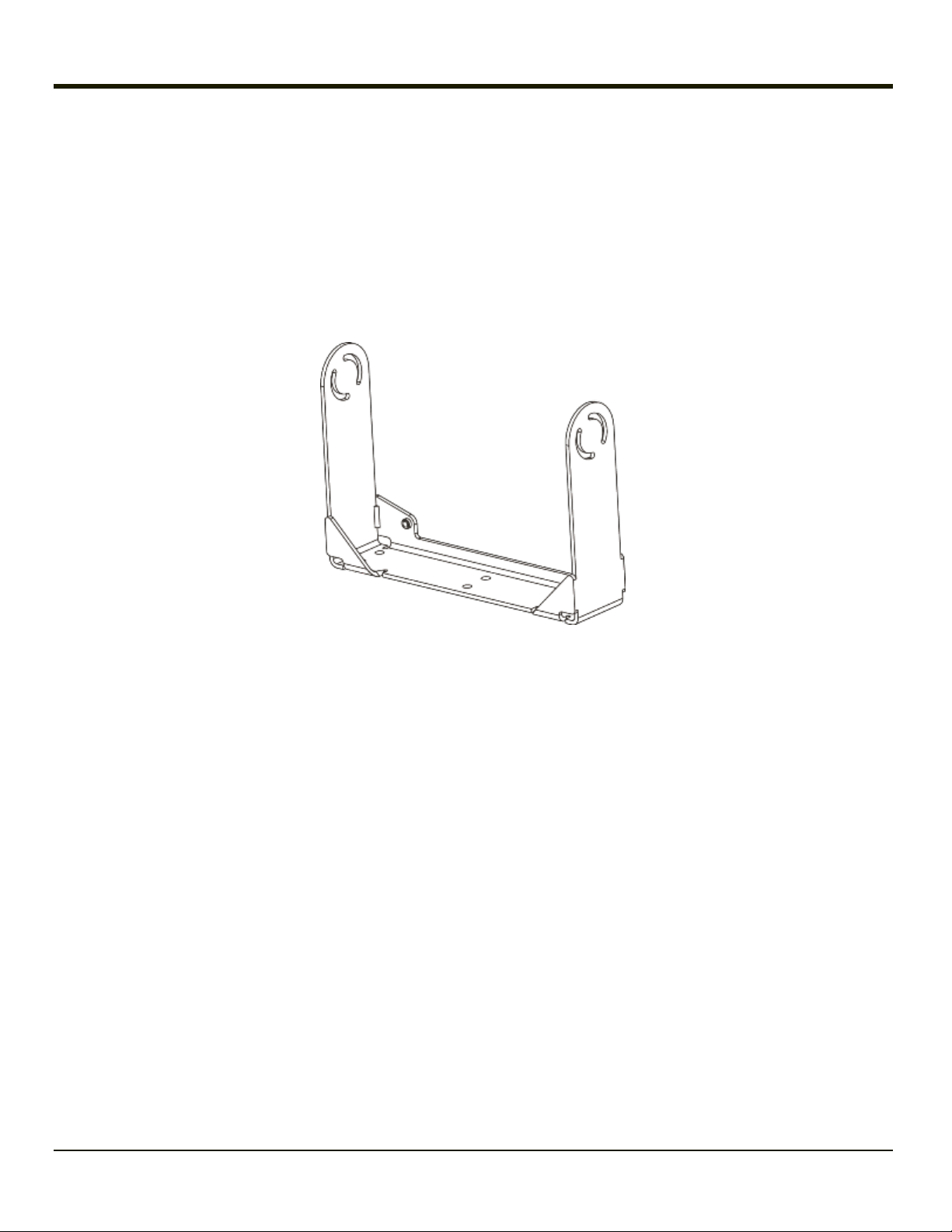
Bottom Mounting Bracket
This bracket is mounted to the vehicle. The VX6 can be mounted to the bottom mounting bracket. Additionally, the UPS battery
pack may be mounted to the bottom mounting bracket.
If the optional UPS battery pack is to be mounted to the bottom bracket, use the following parts included with the UPS battery
pack:
l 1” long aluminum spacer w/through hole (2 each)
l 1/4 flat washer (2 each)
l 1/4 locking washer (2 each)
l screw, pan head, 1/4-20x2 (2 each)
2-2
Page 15
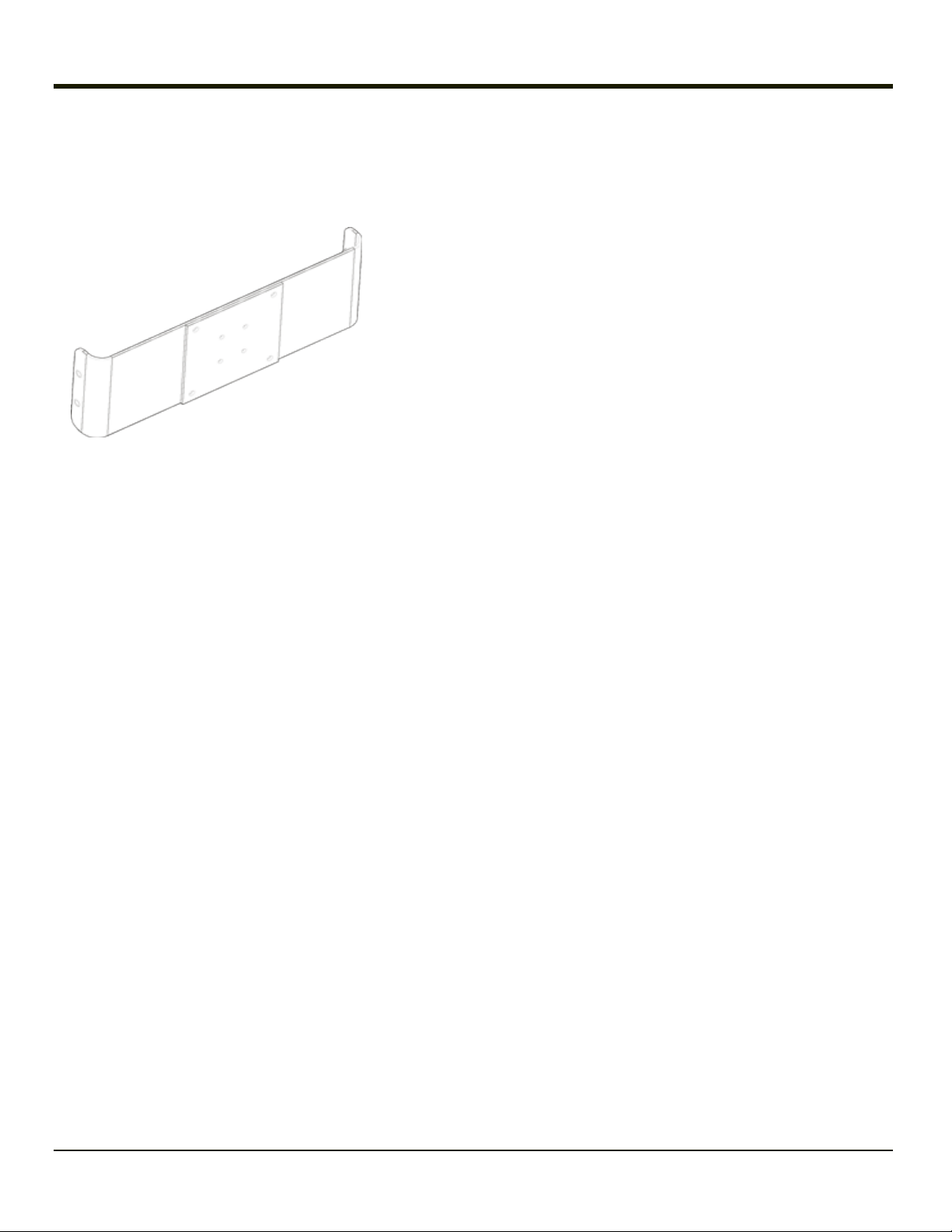
Back Bracket Assembly
Note: Rear Bracket may have a different appearance than shown however hardware and mounting instructions are the
same.
Back Bracket
Hardware:
l 1/4 flat washer (8
each)
l 1/4 locking washer
(8 each)
l 1/4 flat washer (8
each)
2-3
Page 16
Procedure
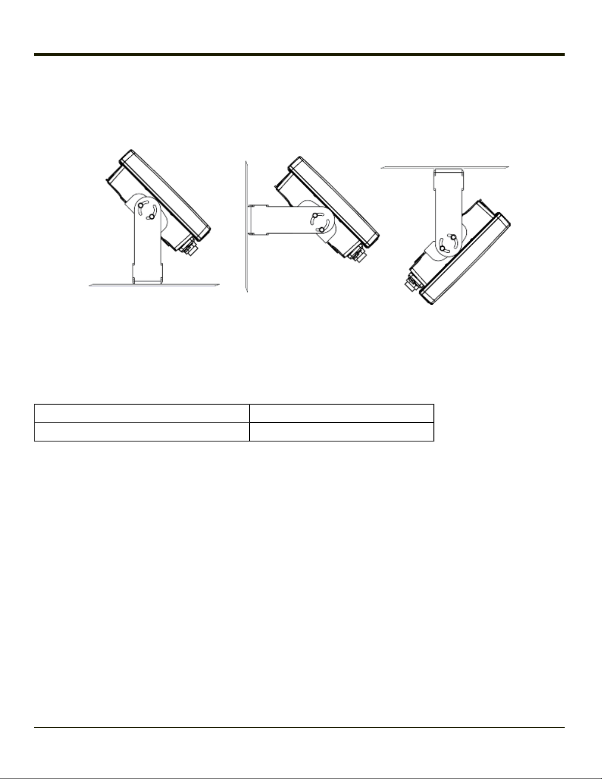
Mounting Positions
The VX6 viewing angle can be adjusted through a wide range to provide the best viewing angle.
Torque Measurement
You will need a torquing tool capable of torquing to 50 inch pounds (5.64±.56 N/m).
Torque all screws and bolts according to the following table:
For these screws and bolts… Torque to
1/4 bolts 50.0±5 in/lb (5.64±.56 N/m)
2-4
Page 17
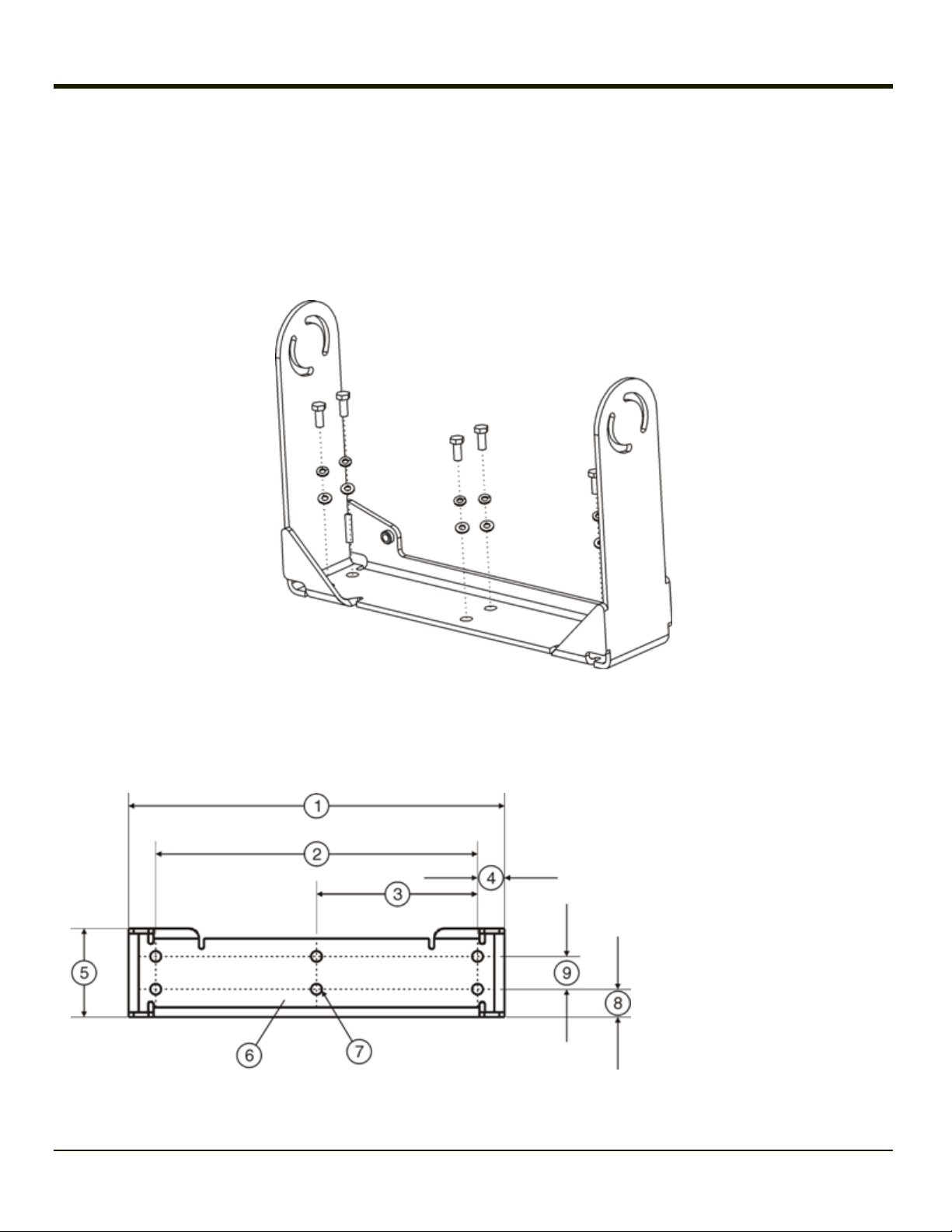
Step 1 - Mount Bottom Mounting Bracket to Vehicle
1. Position the bracket to allow access to the switches and ports on the bottom of the VX6.
2. Attach the bottom mounting bracket to the vehicle mounting surface using a minimum of four 1/4 bolts (or equivalent)
fasteners.
Note: 1/4 bolts and washers not included. It is recommended to use lock washers and flat washers on the fasteners.
IMPORTANT: Mount to the most rigid surface available.
After the bottom bracket has been attached to a rigid surface, you are ready to assemble the VX6 bracket configuration.
Mounting Dimensions
1. 14.40 in / 359.2 mm
2. 12.10 in / 307.3 mm
3. 6.05 in / 153.6 mm
4. 1.02 in / 25.9 mm
5. 3.38 in / 85.85 mm
6. Vehicle Mount
Footprint
7. 0.406 in / 10.312
mm
8. 0.88 in / 22.3 mm
9. 1.25 in / 31.75 mm
U-Bracket Footprint (Not to Scale)
2-5
Page 18
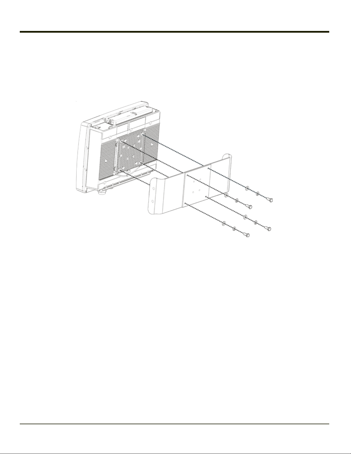
Step 2 - Attach Back Bracket to VX6
Turn the VX6 off before attaching the rear bracket.
2. Place the VX6 face down on a stable surface.
3. Align the rear bracket with the holes on the back of the VX6. Attach with four 1/4- 20x5/8 bolts, using one flat washer and one
locking washer per bolt. Place the locking washer on the bolt before the flat washer.
2-6
Page 19
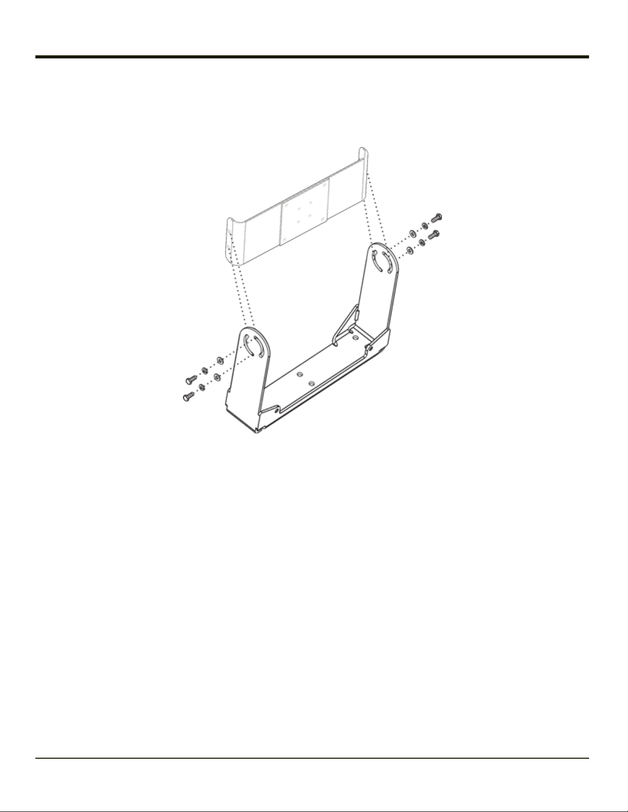
Step 3 - Attach Assembly to Bottom Mount Bracket
1. Place lock washer first, then flat washer on 1/4-20x5/8 bolt. Next insert mounting bolts through the curved apertures in
the bottom mounting bracket and into the screw holes on the side of the back mounting bracket.
2. Loosely tighten each bolt as it is inserted.
Important: Do not torque bolts until all bolts are in place and viewing angle is adjusted.
3. Loosen the hex bolts on both sides to adjust the viewing angle of the mounted VX6.
4. Torque the hex bolts to 50±5 in lb (5.64±.56 N m).
Note: Test the torque on the bolts frequently during operation and re-tighten if necessary to 50±5 in lb (5.64±.56 N m).
2-7
Page 20

Step 4 - Attach UPS Battery Pack
1. If using a UPS battery pack, the battery pack can be mounted to the bottom mounting bracket. Place a locking washer
and then a flat washer on a 1/4-20x2 bolt. Thread the bolt through the UPS Battery Pack, then through the 1” aluminum
spacer and into the mounting bracket.
2. Connect all cables to the VX7. Secure the cables with the strain relief cable clamps, ensuring a slack loop remains
between the cable clamp and the accessory connector.
3. The vehicle mounted bracket and the VX7 are now ready to use.
2-8
Page 21

Completed Assembly
2-9
Page 22

2-10
Page 23

Chapter 3: Install RAM Mounting Brackets
Caution:
This device is intended to transmit RF energy. For protection against RF exposure to humans and in accordance
with FCC rules and Industry Canada rules, this transmitter should be installed such that a minimum separation distance of at least 20 cm (7.8 in.) is maintained between the antenna and the general population. This device is not
to be co-located with other transmitters.
Equipment Needed: Phillips No. 1 screwdriver and a Torque wrench capable of measuring to 50 inch pounds (5.64±.56 N/m).
Note: Torquing tool is not supplied by Honeywell. Bolts, washers, and wrench needed when attaching the bottom mounting
bracket to the vehicle are not supplied by Honeywell.
Several types of RAM mounting options are provided for the VX6:
l RAM Ball or Ram Ball Mount Bracket for back of the VX6
l Available RAM ball base or RAM clamp mount
l Remote mount for UPS battery pack
Before installation begins, verify you have the applicable vehicle mounting bracket assembly components necessary for your
mount type.
3-1
Page 24

RAM Ball Mount System
Components
The RAM mounting assembly consists of the following parts:
1. VX6 RAM ball bracket
2. RAM arm, size D
3. RAM ball base- or - RAM clamp mount
l RAM Clamp Mount includes:
o
Upper Clamp Piece with Ball
o
Lower Clamp Piece
o
Bolts (2 each)
o
Nylon locking nuts (2 each)
l Hardware (not shown):
o
Bolts, 1/4-20x5/8 (4 each)
o
Washers, 1/4 locking (4 each)
o
Washers, 1/4 flat (4 each)
o
RAM wrench
1. Keyboard mounting plate.
2. RAM arm, size C
3. Keyboard mounting bracket
l Hardware (not shown):
o
Screws, 8-32x5/8 (4 each) for use with the 95 key keyboard
o
Screws, 10-32x5/8 (4 each) for use with the 60 key keyboard
o
Bolts, 1/4-20x5/8 (3 each)
o
Washers, 1/4 locking (3 each)
o
Washers, 1/4 flat (3 each)
3-2
Page 25

Procedure
Torque Measurement
You will need a torquing tool capable of torquing to 50 inch pounds (5.64±.56 N/m).
Torque all screws and bolts according to the following table:
For these screws and bolts… Torque to
1/4 bolts 50.0±5 in/lb (5.64±.56 N/m)
Step 1a – Mount Vehicle RAM Mount Bracket
Note: If you are using the RAM clamp mount, please skip to Step 1b.
1. Determine the position for mounting the RAM ball base. Be sure to position the RAM bracket to allow access to the
switches and ports on the bottom of the VX6.
2. Attach the RAM ball base to the vehicle mounting surface using four 1/4 bolts (or equivalent) fasteners.
Note: 1/4 bolts not included.
IMPORTANT: Mount to the most rigid surface available.
3-3
Page 26

Mounting Dimensions
Note: Drill and tap holes for 1/4 bolts.
(Not To Scale)
3-4
Page 27

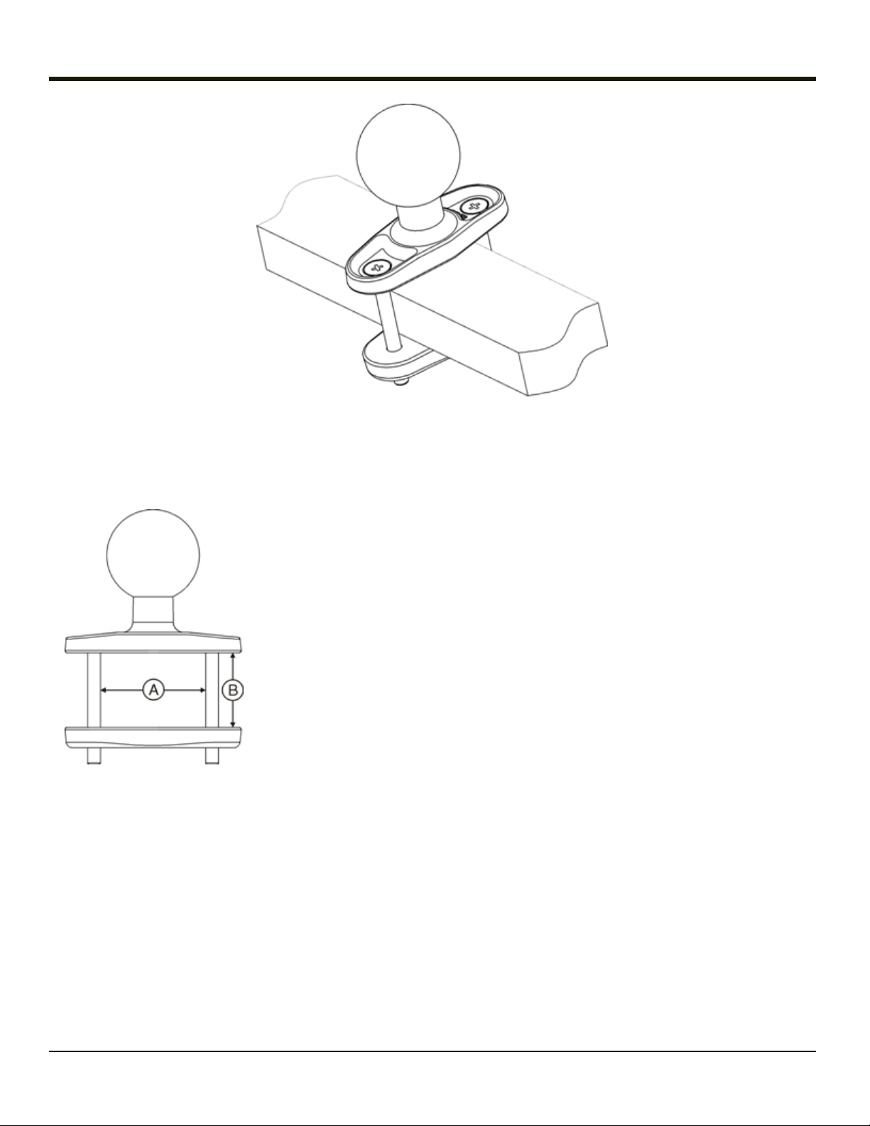
Step 1b – Mount Vehicle RAM Clamp Mount
Note: If you are using the RAM ball base, complete Step 1a and skip Step 1b.
1. Determine the position for mounting the RAM clamp mount. The clamp mount can be used on a beam (such as on a fork
lift truck) up to 2.5” (63.5 mm) wide and approximately 2” (50.8 mm) thick. The clamp may be attached to a thicker beam
by substituting longer bolts (not included). Be sure to position the RAM clamp mount to allow access to the switches
and ports on the bottom of the VX6.
2. Position the upper clamp piece with ball (A) on the beam. Place the bolts (B) through the holes in the upper clamp piece.
3. Position the lower clamp piece (C) below the beam. Align the bolts with the holes in the lower clamp piece.
4. Place the nylon locking nuts (D) on the bolts and tighten the bolts.
3-5
Page 28

Mounting Dimensions
A. 2.56” (65.02 mm)
B. 1.84” (46.74 mm) Varies depending on bolt length
(Not To Scale)
3-6
Page 29

Step 2 – Attach RAM Ball to the VX6
1. Turn the VX6 off before attaching the RAM mount ball.
2. Place the VX6 face down on a stable surface.
3. Position the RAM ball bracket on the rear of the VX6, aligning the curved edge on the RAM mount bracket with the
curved edge on the VX6.
4. Attach with four 1/4-20x5/8 bolts, using one flat washer and one locking washer per bolt. Place the locking washer on
the bolt before the flat washer.
3-7
Page 30

Step 3 – Attach VX6 Assembly to RAM Mount
1. Slip the RAM arm over the ball on the vehicle RAM ball bracket.
2. Insert the ball of the RAM mount bracket into the RAM arm.
3. Adjust the VX6 to the desired position and tighten the knob on the RAM arm using the supplied RAM wrench.
Note: RAM ball base shown.
3-8
Page 31

Completed Assembly
Note: RAM ball base shown.
3-9
Page 32

RAM Bracket Mount System
Components
The RAM mounting assembly consists of the following parts:
1. VX6 RAM ball bracket
2. RAM arm, size D
3. RAM ball base - or - RAM clamp mount
l RAM Clamp Mount includes:
o
Upper Clamp Piece with Ball
o
Lower Clamp Piece
o
Bolts (2 each)
o
Nylon locking nuts (2 each)
l Hardware (not shown):
o
Bolts, 1/4-20x5/8 (4 each)
o
Washers, 1/4 locking (4 each)
o
Washers, 1/4 flat (4 each)
o
RAM wrench
3-10
Page 33

Procedure
Torque Measurement
You will need a torquing tool capable of torquing to 50 inch pounds (5.64±.56 N/m).
Torque all screws and bolts according to the following table:
For these screws and bolts… Torque to
1/4 bolts 50.0±5 in/lb (5.64±.56 N/m)
Step 1a – Mount Vehicle RAM Mount Bracket
Note: If you are using the RAM clamp mount, please skip to Step 1b.
1. Determine the position for mounting the RAM ball base. Be sure to position the RAM bracket to allow access to the
switches and ports on the bottom of the VX6.
2. Attach the RAM ball base to the vehicle mounting surface using four 1/4 bolts (or equivalent) fasteners.
Note: 1/4 bolts not included.
IMPORTANT: Mount to the most rigid surface available.
3-11
Page 34

Mounting Dimensions
Note: Drill and tap holes for 1/4 bolts.
(Not To Scale)
3-12
Page 35

Step 1b – Mount Vehicle RAM Clamp Mount
Note: If you are using the RAM ball base, complete Step 1a and skip Step 1b.
1. Determine the position for mounting the RAM clamp mount. The clamp mount can be used on a beam (such as on a fork
lift truck) up to 2.5” (63.5 mm) wide and approximately 2” (50.8 mm) thick. The clamp may be attached to a thicker beam
by substituting longer bolts (not included). Be sure to position the RAM clamp mount to allow access to the switches
and ports on the bottom of the VX6.
2. Position the upper clamp piece with ball (A) on the beam. Place the bolts (B) through the holes in the upper clamp piece.
3. Position the lower clamp piece (C) below the beam. Align the bolts with the holes in the lower clamp piece.
4. Place the nylon locking nuts (D) on the bolts and tighten the bolts.
3-13
Page 36
Mounting Dimensions
A. 2.56” (65.02 mm)
B. 1.84” (46.74 mm) Varies depending on bolt length
(Not To Scale)
3-14
Page 37

Step 2 – Attach RAM Mount Ball to the VX6
1. Turn the VX6 off before attaching the RAM mount ball.
2. Place the VX6 face down on a stable surface.
3. Position the RAM ball bracket on the rear of the VX6, aligning the curved edge on the RAM mount bracket with the
curved edge on the VX6.
4. Attach with four 1/4-20x5/8 bolts, using one flat washer and one locking washer per bolt. Place the locking washer on
the bolt before the flat washer.
Caution
Failure to use one ¼ flat washer and one ¼ locking washer per bolt can result in damage to the backplate of the
VX6.
3-15
Page 38

Step 3 – Attach VX6 Assembly to RAM Mount
1. Slip the RAM arm over the ball on the vehicle RAM ball bracket.
2. Insert the ball of the RAM mount bracket into the RAM arm.
3. Adjust the VX6 to the desired position and tighten the knob on the RAM arm using the supplied RAM wrench.
Note: RAM ball base shown.
3-16
Page 39

Completed Assembly
Note: RAM ball base shown.
3-17
Page 40

3-18
Page 41

Chapter 4: Connect Cables
There are many cables available for the VX6. This section deals with those cables that are a part of the installation process,
such as:
Various data and communication cables are available for the VX6.
4-1
Page 42

Vehicle 12-80 VDC Power Connection
Caution:
Caution:
Note: Please see Power Adapter Cable for information on adapting a VX1, VX2 or VX4 DC power supply to the VX6.
For proper and safe installation, the input power cable must be connected to a fused circuit on the vehicle. This
fused circuit requires a tenAmp maximum time delay (slow blow) high interrupting rating fuse. If the supply
connection is made directly to the battery, the fuse should be installed in the positive lead within 5 inches of the
battery positive (+) terminal. Note: For North America, a UL Listed fuse is to be used.
For installation by trained service personnel only.
1. To Vehicle Battery
2. To Vehicle Mounted Device or UPS
Battery Pack
3. White (DC+)
4. Black (DC-)
5. Green (GND)
6. 12 – 80 VDC
1. Vehicle Electrical System
2. 10 Amp Slow Blow Fuse
3. DC +
4. DC -
5. Vehicle Chassis
6. White
7. Black
8. Green
Note: Correct electrical polarity is required for safe and proper installation. Connecting the cable to the VX6 with the polarity
reversed will cause the VX6 fuse to be blown. See the following figure titled “Vehicle Connection Wiring Color Codes”
for additional wire color-coding specifics.
4-2
Page 43

Connect Vehicle 12-80VDC Connection
1. The VX6 must be turned off and the power cable must be UNPLUGGED from the VX6.
2. While observing the fuse requirements specified above, connect the power cable as close as possible to the actual
battery terminals of the vehicle. When available, always connect to un-switched terminals in vehicle fuse panel, after
providing proper fusing.
ATTENTION: For uninterrupted power, electrical supply connections should not be made at any point after the ignition
switch of the vehicle.
3. Route the power cable the shortest way possible. The cable is rated for a maximum temperature of 105°C (221°F).
When routing this cable it should be protected from physical damage and from surfaces that might exceed this
temperature.
Do not expose the cable to chemicals or oil that may cause the wiring insulation to deteriorate.
Always route the cable so that it does not interfere with safe operation and maintenance of the vehicle.Use proper
electrical and mechanical fastening means for terminating the cable. Properly sized “crimp” type electrical terminals are
an accepted method of termination. Please select electrical connectors sized for use with 18AWG (1mm2) conductors.
Wiring color codes for Honeywell supplied DC input power cabling:
Vehicle Supply Wire Color
+12 - 80VDC (DC +) White
Return (DC -) Black
Vehicle Chassis GND Green
4. Provide mechanical support for the cable by securing it to the vehicle structure at approximately one foot intervals,
taking care not to over tighten and pinch conductors or penetrate outer cable jacket.
5. Refer to the following sections to complete the power connection to the VX6.
4-3
Page 44

Connect VX6 without a UPS Battery Pack
A. Vehile Battery
B. Vehicle Power
Connection Cable
C. VX6 Computer
1. Connect the power cable to the vehicle’s electrical system as described in “Connect Vehicle 12-80VDC Connection”.
2. Connect the power cable to the VX6 by aligning the water-tight connector pins to the power connector on the bottom of
the VX6; push down on the water-tight connector and twist it to fasten securely.
3. Turn the VX6 on.
4-4
Page 45

Connect VX6 to an Integrated Mount UPS Battery Pack
A. Vehicle Battery
B. Vehicle Power
Connection Cable
C. UPS Battery Pack
D. VX6 Computer
1. Connect the power cable to the vehicle’s electrical system as described in Connect Vehicle 12-80VDC Connection.
2. Connect the power cable to the UPS battery pack by aligning the water-tight connector pins to the input connector
(labeled “From Vehicle”); push down on the water-tight connector and twist it to fasten securely.
3. Connect the output cable (labeled “To Computer”) from the UPS battery pack to the power connector on the bottom of
the VX6 by aligning the water-tight connector to the power connector; push down on the water-tight connector and twist
it to fasten securely.
4. Turn the VX6 on.
4-5
Page 46

Connect VX6 to a Remotely Mounted UPS Battery Pack
A. Vehicle Battery
B. Vehicle Power Connection
Cable
C. UPS Battery Pack
D. Extension Cable
E. VX6 Computer
1. Connect the power cable to the vehicle’s electrical system as described in Connect Vehicle 12-80VDC Connection.
2. Connect the power cable to the UPS battery pack by aligning the water-tight connector pins to the input connector
(labeled “From Vehicle”); push down on the water-tight connector and twist it to fasten securely.
3. Connect the output cable (labeled “To Computer”) from the UPS battery pack to the extension cable by aligning the
water-tight connector to the input end of the extension cable; push down on the water-tight connector and twist it to
fasten securely.
4. Route the extension cable the shortest way possible. The cable is rated for a maximum temperature of 105°C (221°F).
When routing this cable it should be protected from physical damage and from surfaces that might exceed this
temperature.
Do not expose the cable to chemicals or oil that may cause the wiring insulation to deteriorate. Always route the cable
so that it does not interfere with safe operation and maintenance of the vehicle.
5. Provide mechanical support for the cable by securing it to the vehicle structure at approximately one foot intervals,
taking care not to over tighten and pinch conductors or penetrate outer cable jacket.
6. Connect the output end of the extension cable to the power connector on the bottom of the VX6 by aligning the watertight connector to the power connector; push down on the water-tight connector and twist it to fasten securely.
7. Turn the VX6 on.
4-6
Page 47

Power Adapter Cable
Honeywell offers an adapter cable (part no. 9000A077CBLPWRADPTR) to adapt certain Honeywell VX1, VX2 or VX4 DC
power supplies to the VX6. Please read and follow all cautions below to determine if your present power supply can be used
with the VX6.
1. VX6 Connector
2. VX1/2/4 Power Supply
Connector
Caution
Caution
Caution
Caution
Note: For more information on the 12-80VDC direct, UPS battery pack and extension cable connections please refer to the
This document assumes the VX1/2/4 DC power cable, if applicable, is already properly connected to your vehicle.
If this is not the case, please refer to the “VX1 User’s Guide”, “VX2 User’s Guide” or “VX4 User’s Guide” for direct
vehicle connection details.
For use only with VX1/2/4 DC power cables with yellow colored cable containing 18AWG wires.
Do not use this cable with VX1/2/4 DC power cables with gray colored cable containing 22AWG wires. These
power cables must be replaced with a VX5/6/7 power cable.
When a DC power cable that is eight feet or longer is in a 12V application, there may be an excessive voltage drop
over the longer cable. If this occurs, a new power cable is required.
Do not use this adapter with AC power supplies originally designed for the 1380, 1390, VX1, VX2 or VX4. These
power supplies do not have sufficient power for the VX6.
appropriate section earlier in this manual.
Connect Power Adapter Cable
1. The VX6 must be turned off and the power cable must be UNPLUGGED from the VX6.
2. Attach the smaller end of the Power Adapter Cable to the VX1/2/4 power cable by aligning the water-tight connector
pins to the power cable connector. Push down on the water-tight connector and twist it to fasten securely.
3. Connect the larger end of the Power Cable directly to the VX6 or to a UPS battery pack, as desired. Please refer to
the appropriate section (12-80VDC direct, UPS battery pack and extension cable connections) earlier in this manual
for UPS battery pack connection details.
4-7
Page 48

External Power Supply, Optional
If 12V to 80V DC power is not available – for example, in an office environment – an optional external Input Power Supply can
be used to convert AC wall power to an appropriate DC level.
The Honeywell-approved AC Power Adapter is only intended for use in a 25ºC (77ºF) maximum ambient temperature
environment.
1. AC Input Cable (US only)
2. DC Output Cable
In North America, this unit is intended for use with a UL Listed ITE power supply with output rated 12 – 80 VDC, minimum
75W. Outside North America, this unit is intended for use with an IEC certified ITE power supply with output rated 12 – 80
VDC, minimum 75W.
The external power supply may be connected to either a 120V, 60Hz supply or, outside North America, to a 230V, 50Hz
supply, using the appropriate detachable cordset. In all cases, connect to a properly grounded source of supply provided with
maximum 15 Amp overcurrent protection (10 Amp for 230V circuits).
Connect External Power Supply
1. Turn the VX6 off.
2. Connect the detachable cordset provided by Honeywell (US only, all others must provide their own cable) to the
external power supply (IEC 320 connector).
3. Plug the cordset into appropriate, grounded, electrical supply receptacle (AC mains).
4. Connect the watertight connector end to the VX6 Power Connector by aligning the connector pins to the power
connector; push down on the watertight connector and twist it to fasten securely.
5. Turn the VX6 on.
4-8
Page 49

Strain Relief Cable Clamps
Equipment Required: Phillips screwdriver (not supplied by Honeywell)
There are strain relief cable clamps secured to the back of the VX6. Use the strain relief clamps to secure audio, power, and
I/O cables attached to the VX6.
1. Remove the strain relief clamp from the back of the VX6 by turning the screw counterclockwise. Put the screw aside in a
safe location.
2. Slide the strain relief clamp over the cable.
3. Using a Phillips screwdriver and the screw that was removed, refasten the clamp holding the cable to the VX6. Do not
stretch the cable. Leave enough slack in the cable to allow it to be connected and disconnected easily when needed.
4. Continue in this manner until all cables are secured to the VX6.
4-9
Page 50

Uninterruptible Power Supply Battery Pack
An optional Uninterruptible Power Supply (UPS) battery pack is designed to provide power to the VX6 for short periods of time
when vehicle power is unavailable (such as when vehicle batteries are swapped).
Fully charged, the UPS battery pack powers the VX6 for a minimum of 15 minutes at 25º C (77º F) ambient temperature.
The Power Status LED on the VX6 indicates the UPS battery pack status:
Green Running on 12V – 80V power input
Solid Yellow Running on UPS battery pack power, battery is not low on power
Flashing Yellow Running on UPS battery pack power, battery is critically low
UPS Battery Pack Remote Mounting
The optional UPS battery pack must be mounted remotely when using the RAM mount system or a U-bracket designed for a
previous model Honeywell computer. The remote mount can also be used with the VX6 U-bracket assembly if it is not
convenient to mount the UPS battery pack to the U-bracket.
A six foot extension cable is available to connect the UPS battery pack to the VX6.
1. Position the UPS battery pack to allow cables to reach the vehicle battery and the VX6.
2. Attach the UPS battery pack to the vehicle mounting surface using two 1/4 bolts, lock washers and flat washers (or
equivalent) fasteners.
Note: 1/4 bolts and washers not included.
IMPORTANT:Mount to the most rigid surface available.
4-10
Page 51

UPS Battery Pack Remote Mounting Dimensions
1. 11.00” / 279.40 mm
2. 10.23” / 259.80 mm
3. 0.38” / 9.65 mm
4. 1.39” / 35.31 mm
5. 3.04” / 77.22 mm
6. 0.30” / 7.62 mm
4-11
Page 52

Fuse Replacement for the VX6
The VX6 uses a 100V, 10A time delay (slow blow), high current interrupting rating fuse that is externally accessible and user
replaceable.
Should it need replacement, replace with same size, rating and type of fuse – Littlefuse 0234010 or Optifuse MSC-10A
(5x20mm).
1. Fuse
2. Twist in this direction to
remove
3. Twist in this direction to
insert
Caution
Fuse has voltage on it even when power is off. Always disconnect input power before changing fuse.
1. Turn the VX6 off and disconnect the power cable from the VX6.
2. While holding the VX6 over a level surface, push the fuse cover in and twist it one quarter turn counterclockwise. A flat
head screwdriver may be used to twist the fuse cover.
3. Remove the fuse.
4. Discard the fuse and place a new fuse in the holder.
5. Push the fuse in and twist it clockwise one quarter turn.
6. Reconnect the power cable to the VX6.
4-12
Page 53

Connect Antenna
Several antenna options are available for the VX6. Options include:
l single external antenna
l dual external antennas
l single or dual remote vehicle mount antennas
l internal antenna (installed when manufactured)
Note: VX6’s are equipped with a radio and require an antenna. Some VX6’s may be equipped with a dual antenna option.
For these VX6’s, an external antenna must be connected to each antenna connector.
Connect External Antenna
If the internal antenna option was selected, there are no external antenna connectors on the VX6.
The external antenna connectors are located on the top of the VX6.
1. Antenna
2. Antenna Connector
Place the antenna over the antenna connector. Push the antenna down and twist it clockwise until the antenna is secured.
Repeat for second antenna connector, if present.
Adjust the antenna angle to improve RF communications with the computer network.
Note: Substitution of antennas is not permitted unless authorized by Honeywell. Use of unauthorized antennas will void the
FCC emissions certification of the VX6.
4-13
Page 54

Internal Antenna
If the internal antenna option is ordered, an antenna is mounted on the inside of the user access panel cover (located on top of
the VX6).
The internal antenna assembly has two antenna cables.
Attach the antenna cables to the radio card.
When this process is complete, reattach the access cover screws using a torque wrench capable of measuring to 9±1 inch
pounds force (1.016±.11 N m).
The screws must be fastened to 9 inch pounds each. The screws require a Phillips size 1 driver head.
4-14
Page 55

Remote Antenna Installation Kit
l The Remote Antenna Installation Kit consists of the base plate and cable.
l Depending on the antenna kit selected, the connector to the VX6 is either straight or a 90° angle.
l Antenna is sold separately. Cable length varies by kit.
l Tools are not included.
The remote antenna base is mounted on the top of a forklift, truck or other vehicle and cabled to the VX6 inside the vehicle. The
cable is available in different lengths and with a straight or right angle adapter on the end.
The Vehicle Remote Mount Antenna cannot be used by devices with an internal antenna.
4-15
Page 56

Components and Mounting Diagram
1. Nut
2. Washer
3. Washer
4. Mounting Plate
5. To Antenna
6. To VX6 Antenna
Connector
7. Antenna
Typical Installation
4-16
1. Antenna
2. Mounting Plate
3. Vehicle Safety Cage
4. Coaxial Cable
5. Vehicle Mounted VX6
Page 57

Remote Antenna Mounting Instruction
1. Attach and secure the mounting plate to the highest point on the safety cage, following these precautions:
l The plate must be mounted so the antenna is not damaged while the vehicle or any of its parts are
moving.
l The mounting plate must be parallel to the floor.
l If the VX6 requires two antennas, they must be mounted at least 12 inches (304.8mm) apart.
2. Attach the female connector of the coaxial cable to the antenna connector on the vehicle mounted VX6.
3. Insert the male connector on the coaxial cable though the hole in the mounting plate.
4. Secure the connector to the mounting plate with the washer and hex nut.
5. Use cable ties to secure the coaxial cable to the vehicle as necessary. Make sure the cable is routed so it is not
damaged by any moving parts of the vehicle.
6. Attach the antenna to the male connector on the end of the coaxial cable. The antenna must be mounted in a vertical
position.
7. If the VX6 is using dual antennas (diversity option), repeat these steps for the second antenna.
4-17
Page 58

4-18
Page 59

Chapter 5: Technical Assistance
If you need assistance installing or troubleshooting your device, please contact us by using one of the methods below:
Knowledge Base: www.hsmknowledgebase.com
Our Knowledge Base provides thousands of immediate solutions. If the Knowledge Base cannot help, our Technical Support
Portal (see below) provides an easy way to report your problem or ask your question.
Technical Support Portal: www.hsmsupportportal.com
The Technical Support Portal not only allows you to report your problem, but it also provides immediate solutions to your
technical issues by searching our Knowledge Base. With the Portal, you can submit and track your questions online and send
and receive attachments.
Web form: www.hsmcontactsupport.com
You can contact our technical support team directly by filling out our online support form. Enter your contact details and the
description of the question/problem.
Telephone: www.honeywellaidc.com/locations
For our latest contact information, please check our website at the link above.
Product Service and Repair
Honeywell International Inc. provides service for all of its products through service centers throughout the world. To obtain
warranty or non-warranty service, please visit www.honeywellaidc.comand select Support > Contact Service and Repair
to see your region’s instructions on how to obtain a Return Material Authorization number (RMA #). You should do this prior to
returning the product.
Limited Warranty
Honeywell International Inc. ("HII") warrants its products to be free from defects in materials and workmanship and to conform
to HII’s published specifications applicable to the products purchased at the time of shipment. This warranty does not cover
any HII product which is (i) improperly installed or used; (ii) damaged by accident or negligence, including failure to follow the
proper maintenance, service, and cleaning schedule; or (iii) damaged as a result of (A) modification or alteration by the
purchaser or other party, (B) excessive voltage or current supplied to or drawn from the interface connections, (C) static
electricity or electro-static discharge, (D) operation under conditions beyond the specified operating parameters, or (E) repair or
service of the product by anyone other than HII or its authorized representatives.
This warranty shall extend from the time of shipment for the duration published by HII for the product at the time of purchase
("Warranty Period"). Any defective product must be returned (at purchaser’s expense) during the Warranty Period to HII factory
or authorized service center for inspection. No product will be accepted by HII without a Return Materials Authorization, which
may be obtained by contacting HII. In the event that the product is returned to HII or its authorized service center within the
Warranty Period and HII determines to its satisfaction that the product is defective due to defects in materials or workmanship,
HII, at its sole option, will either repair or replace the product without charge, except for return shipping to HII.
EXCEPT AS MAY BE OTHERWISE PROVIDED BY APPLICABLE LAW, THE FOREGOING WARRANTY IS IN LIEU OF
ALL OTHER COVENANTS OR WARRANTIES, EITHER EXPRESSED OR IMPLIED, ORAL OR WRITTEN, INCLUDING,
WITHOUT LIMITATION, ANY IMPLIED WARRANTIES OF MERCHANTABILITY OR FITNESS FOR A PARTICULAR
PURPOSE, OR NON-INFRINGEMENT.
HII’S RESPONSIBILITY AND PURCHASER’S EXCLUSIVE REMEDY UNDER THIS WARRANTY IS LIMITED TO THE
REPAIR OR REPLACEMENT OF THE DEFECTIVE PRODUCT WITH NEW OR REFURBISHED PARTS. IN NO EVENT
5-1
Page 60

SHALL HII BE LIABLE FOR INDIRECT, INCIDENTAL, OR CONSEQUENTIAL DAMAGES, AND, IN NO EVENT, SHALL
ANY LIABILITY OF HII ARISING IN CONNECTION WITH ANY PRODUCT SOLD HEREUNDER (WHETHER SUCH
LIABILITY ARISES FROM A CLAIM BASED ON CONTRACT, WARRANTY, TORT, OR OTHERWISE) EXCEED THE
ACTUAL AMOUNT PAID TO HII FOR THE PRODUCT. THESE LIMITATIONS ON LIABILITY SHALL REMAIN IN FULL
FORCE AND EFFECT EVEN WHEN HII MAY HAVE BEEN ADVISED OF THE POSSIBILITY OF SUCH INJURIES,
LOSSES, OR DAMAGES. SOME STATES, PROVINCES, OR COUNTRIES DO NOT ALLOW THE EXCLUSION OR
LIMITATIONS OF INCIDENTAL OR CONSEQUENTIAL DAMAGES, SO THE ABOVE LIMITATION OR EXCLUSION MAY
NOT APPLY TO YOU.
All provisions of this Limited Warranty are separate and severable, which means that if any provision is held invalid and
unenforceable, such determination shall not affect the validity of enforceability of the other provisions hereof. Use of any
peripherals not provided by the manufacturer may result in damage not covered by this warranty. This includes but is not
limited to: cables, power supplies, cradles, and docking stations. HII extends these warranties only to the first end-users of the
products. These warranties are non-transferable.
The duration of the limited warranty for the VX6is 1 year.
The duration of the limited warranty for the VX6 Vehicle Mount Assembly is 1 year.
The duration of the limited warranty for the VX6 external UPS battery is 1 year.
The duration of the limited warranty for the VX6AC power supply and cables is 1 year.
The duration of the limited warranty for the VX6DC-DC Converter is 1 year.
The duration of the limited warranty for the VX6cables (USB, Serial, Communication, Power) is 1 year.
5-2
Page 61

5-3
Page 62

Honeywell Scanning & Mobility
9680 Old Bailes Road
Fort Mill, SC 29707
www.honeywellaidc.com
E-EQ-VX6OGWW
Rev E
10/12
 Loading...