

Honeywell VX3Plus Reference Manual

VX3Plus
Vehicle-Mount Computer
Microsoft®Windows®CE 5 Operating System
Reference Guide

Disclaimer
Honeywell International Inc. (“HII”) reserves the right to make changes in specifications and other information contained in this
document without prior notice, and the reader should in all cases consult HII to determine whether any such changes have
been made. The information in this publication does not represent a commitment on the part of HII.
HII shall not be liable for technical or editorial errors or omissions contained herein; nor for incidental or consequential damages
resulting from the furnishing, performance, or use of this material.
This document contains proprietary information that is protected by copyright. All rights are reserved. No part of this document
may be photocopied, reproduced, or translated into another language without the prior written consent of HII.
© 2008-2012 Honeywell International Inc. All rights reserved.
Web Address: www.honeywellaidc.com
RFTerm is a trademark or registered trademark of EMS Technologies, Inc. in the United States and/or other countries.
Microsoft®Windows, ActiveSync®, MSN, Outlook®, Windows Mobile®, the Windows logo, and Windows Media are
registered trademarks or trademarks of Microsoft Corporation.
Intel®and Intel XScale®are trademarks or registered trademarks of Intel Corporation or its subsidiaries in the United States
and other countries.
Summit Data Communications, Inc. Summit Data Communications, the Summit logo, and “The Pinnacle of Performance” are
trademarks of Summit Data Communications, Inc.
The Bluetooth®word mark and logos are owned by the Bluetooth SIG, Inc.
Symbol®is a registered trademark of Symbol Technologies. MOTOROLA, MOTO, MOTOROLA SOLUTIONS and the
Stylized M Logo are trademarks or registered trademarks of Motorola Trademark Holdings, LLC and are used under license.
Wavelink®, the Wavelink logo and tagline, Wavelink Studio™, Avalanche Management Console™, Mobile Manager™, and
Mobile Manager Enterprise™ are trademarks of Wavelink Corporation, Kirkland.
RAM®and RAM Mount™ are both trademarks of National Products Inc., 1205 S. Orr Street, Seattle, WA 98108.
Acrobat®Reader © 2012with express permission from Adobe Systems Incorporated.
Other product names or marks mentioned in this document may be trademarks or registered trademarks of other companies
and are the property of their respective owners.
Patents
For patent information, please refer to www.honeywellaidc.com/patents.
Limited Warranty
Refer to www.honeywellaidc.com/warranty_information for your product’s warranty information.

Table of Contents
Chapter 1: Introduction 1-1
End User License Agreement (EULA) 1-1
Reboot 1-2
Warmboot 1-2
Coldboot 1-2
Components 1-3
Front 1-3
Back 1-4
Endcap 1-5
Endcap Options 1-5
VX3Plus without a Touchscreen 1-5
Chapter 2: Hardware 2-1
System Hardware 2-1
802.11b/g and a/b/g Wireless Client 2-2
Central Processing Unit 2-2
System Memory 2-2
Video Subsystem 2-2
Power Supply 2-2
Backup Battery 2-2
Audio Interface 2-3
PCMCIA and CF Slots 2-3
PCMCIA – Network or SRAM Cards 2-3
CF – CompactFlash Card 2-3
Bluetooth LXEZ Pairing 2-4
Power Modes 2-5
On Mode 2-5
User Idle Mode 2-5
Primary Events 2-5
Suspend Mode 2-5
Off Mode 2-6
External Connectors 2-7
RS-232 Connector (COM1 or COM3) 2-7
Technical Specifications - Connection Cable 2-7
RTS/CTS Handshaking and the Serial Port 2-8
Screen Blanking Cable 2-9
Serial Cable 2-9
Sample Cable for Screen Blanking 2-9
i

USB-C Connector 2-10
USB-H Connector 2-11
Audio Connector 2-13
Power Supply Connector 2-13
Antenna Connector (Optional) 2-13
Vehicle Remote Antenna Mount 2-14
Programmable Scan Buttons 2-14
Field Exit Key Function (IBM 5250 Only) 2-14
Keypad 2-15
Key Functions 2-15
Programmable 2-15
Enter 2-15
2nd 2-15
Ctrl 2-15
Alt 2-16
Shft 2-16
Spc 2-16
Caps Key and CapsLock Mode 2-16
Keypad Shortcuts 2-16
Custom Key Maps 2-16
LED Functions 2-17
2nd 2-17
ALT 2-17
CTRL 2-17
SHFT 2-17
CAPS 2-17
STAT 2-17
Speaker 2-17
Display 2-18
Touchscreen 2-18
Power Supply 2-18
External Power Supply 2-19
Endcap Combinations 2-19
Serial / USB-C Endcap 2-19
Dual Serial Endcap 2-19
Serial / USB-H Endcap 2-20
USB-C / USB-H Endcap 2-20
Chapter 3: Software 3-1
Introduction 3-1
ii

Operating System 3-1
Windows CE Operating System 3-1
General Windows CE Keyboard Shortcuts 3-1
Warmboot 3-3
Coldboot 3-3
Clearing Persistent Storage / Reset to Default Settings 3-3
Folders Copied at Startup 3-3
Saving Changes to the Registry 3-3
Software Load 3-5
Software Applications 3-5
ActiveSync 3-5
Bluetooth (Optional) 3-5
Java (Optional) 3-6
RFTerm (Optional) 3-6
Avalanche 3-6
Software Development 3-6
Access Files on the CF/SD Card 3-6
VX3Plus Utilities 3-7
LAUNCH.EXE 3-7
LAUNCH.EXE and Persistent Storage 3-9
REGEDIT.EXE 3-9
REGLOAD.EXE 3-9
REGDUMP.EXE 3-9
WARMBOOT.EXE 3-9
WAVPLAY.EXE 3-9
VX3Plus Command-line Utilities 3-9
COLDBOOT.EXE 3-9
PrtScrn.EXE 3-10
Desktop 3-11
Desktop Icons 3-11
Taskbar 3-12
My Device Folders 3-12
Wavelink Avalanche Enabler (Optional) 3-13
Internet Explorer 3-13
Start Menu Program Options 3-14
Communication 3-14
ActiveSync 3-15
Start FTP Server / Stop FTP Server 3-15
Summit 3-15
Certs 3-15
iii

Command Prompt 3-15
eXpress Scan 3-15
Internet Explorer 3-16
Media Player 3-16
Microsoft File Viewers 3-16
Microsoft WordPad 3-16
Remote Desktop Connection 3-16
Settings 3-17
Transcriber 3-17
Windows Explorer 3-17
Taskbar 3-18
General Tab 3-18
Advanced Tab 3-18
Expand Control Panel 3-18
Clear Contents of Document Folder 3-19
Taskbar Icons 3-19
VX3Plus OS Upgrade 3-19
Introduction 3-19
Preparation 3-19
Procedure 3-20
ActiveSync 3-20
Introduction 3-20
Initial Setup 3-21
Connect via USB 3-21
Cable for USB ActiveSync Connection: 3-21
Serial Connection 3-22
Cable for Serial ActiveSync Connection 3-22
Wireless Connection 3-23
VX3Plus without Touchscreen 3-23
Synchronizing from the Mobile Device 3-23
Explore 3-23
Backup Data Files using ActiveSync 3-23
Prerequisites 3-23
Serial Port Transfer 3-24
USB Transfer 3-24
Connect 3-24
Disconnect 3-24
Cold Boot and Loss of Host Re-connection 3-24
ActiveSync Help 3-25
Configuring the VX3Plus with LXEConnect 3-26
iv

Install LXEConnect 3-26
Using LXEConnect 3-28
Control Panel 3-30
About 3-32
Version Tab and the Registry 3-32
Language and Fonts 3-32
Identifying Software Versions 3-33
MAC Address 3-33
Accessibility 3-34
Administration - AppLock 3-36
Setup a New Device 3-36
Administration Mode 3-37
End User Mode 3-37
Passwords 3-38
End-User Switching Technique 3-38
Using a Stylus Tap 3-38
Using the Switch Key Sequence 3-39
Hotkey (Activation hotkey) 3-39
Application Configuration 3-39
Application Panel 3-40
Launch Button 3-41
Auto At Boot 3-41
Auto Re-Launch 3-42
Manual (Launch) 3-43
Allow Close 3-43
Match 3-44
End User Internet Explorer (EUIE) 3-44
Security Panel 3-45
Hotkey 3-45
Password 3-45
Options Panel 3-46
Launch timeout 3-46
Replace timeout 3-46
Restart timeout 3-46
Status Panel 3-46
View 3-47
Log 3-47
Save As 3-47
AppLock Help 3-48
AppLock Error Messages 3-48
v

Bluetooth 3-56
Bluetooth Devices 3-57
Discover 3-58
Stop Button 3-58
Bluetooth Device List 3-59
Clear Button 3-59
Bluetooth Device Menu 3-59
Right Click Menu Options 3-60
Bluetooth Device Properties 3-61
Settings 3-62
Turn Off Bluetooth 3-62
Options 3-63
Reconnect 3-64
Options 3-65
OPP Setup 3-67
OPP Send 3-69
Buttons 3-69
About 3-70
Using Bluetooth 3-71
Bluetooth Devices Display - Before Discovering Devices 3-71
Initial Configuration 3-71
Subsequent Use 3-72
Bluetooth Indicators 3-73
Bluetooth Barcode Reader Setup 3-73
Prerequisites 3-73
VX3Plus with Label 3-74
VX3Plus without Label 3-74
Bluetooth Beep and LED Indications 3-76
Bluetooth Printer Setup 3-76
Easy Pairing and Auto-Reconnect 3-77
Using OPP 3-78
Pairing with an OPP Device 3-78
Remote Device Pushes File to VX3Plus 3-78
VX3Plus Pushes File to Remote Device 3-79
LXEZ Pairing and External Application 3-79
Certificates 3-80
Date / Time 3-81
Device Management 3-82
Dialing 3-83
Display 3-84
vi

Background 3-84
Appearance 3-84
Backlight 3-85
Input Panel 3-86
Installed Programs 3-87
Internet Options 3-88
Keyboard 3-91
KeyPad 3-92
KeyMap Tab 3-93
How to Remap a Single Key 3-93
How to Remap a Key Sequence 3-93
How to Remap an Application 3-93
How to Remap a Command 3-94
LaunchApp Tab 3-94
RunCmd Tab 3-95
License Viewer 3-96
Mixer 3-97
Mouse 3-98
MX3X-VXC Options 3-99
Communication 3-99
Enable TCP/IP Version 6 3-99
Allow Remote Desktop Autologon 3-99
Autolaunch TimeSync 3-99
Disable SNMP 3-100
Misc 3-101
CapsLock 3-101
Touch Screen Disable 3-101
Enable RFTerm Auto Launch 3-101
Enable Auto Launch IP Wait 3-101
IP Wait Timeout 3-102
Status Popup 3-103
Network and Dialup Options 3-104
Create a New Connection 3-104
Network Capture 3-105
Netlog 3-105
NDISLog 3-106
Owner 3-108
Password 3-110
PC Connection 3-111
PCMCIA 3-112
vii

PCMCIA Tab Options 3-112
CF Tab Options 3-113
IntATA Tab Options 3-113
Regional and Language Settings 3-114
Remove Programs 3-116
Scanner 3-117
Bar Code Readers 3-117
Return to Factory Default Settings 3-117
Barcode Processing Overview 3-117
Factory Default Settings 3-118
Main Tab 3-119
Screen Blanking 3-120
Technical Specifications - Screen Blanking Cable 3-121
Serial cable 3-121
Pinout 3-121
Keys Tab 3-122
COM1 Tab 3-123
COM2 Tab 3-124
COM3 Tab 3-125
Serial Port Pin 9 3-126
Enable Handshaking 3-126
Barcode Tab 3-127
Buttons 3-127
Enable Code ID 3-128
Options 3-128
Notes 3-128
Barcode – Custom Identifiers 3-129
Parameters 3-129
Name text box 3-129
ID Code text box 3-129
Buttons 3-130
Add 3-130
Insert 3-130
Edit 3-130
Clear All 3-130
Remove 3-130
Control Code Replacement Examples 3-130
Barcode Processing Examples 3-131
Barcode - Ctrl Char Mapping 3-132
Translate All 3-132
viii

Parameters 3-132
Barcode - Symbology Settings 3-133
Parameters 3-134
Strip Leading/Trailing Control 3-135
Barcode Data Match List 3-135
Barcode Data Match Edit Buttons 3-136
Match List Rules 3-136
Add Prefix/Suffix Control 3-137
Length Based Barcode Stripping 3-137
Hat Encoding 3-140
Stylus 3-142
System 3-143
General Tab 3-143
Memory Tab 3-144
Device Name Tab 3-144
Copyrights Tab 3-145
Terminal Server Client Licenses 3-146
Volume and Sounds 3-147
Good Scan and Bad Scan Sounds 3-148
WiFi 3-149
Chapter 4: Enabler Installation and Configuration 4-1
Introduction 4-1
Installation 4-1
Installing the Enabler on Mobile Devices 4-1
Enabler Uninstall Process 4-2
Stop the Enabler Service 4-2
Update Monitoring Overview 4-3
Mobile Device Wireless and Network Settings 4-4
Preparing a Device for Remote Management 4-5
Using Wavelink Avalanche to Upgrade System Baseline 4-6
Part 1 – Bootstrapping the RMU 4-6
Part 2 – Installing Packages 4-6
Version Information on Mobile Devices 4-6
User Interface 4-7
Enabler Configuration 4-7
File Menu Options 4-8
Avalanche Update using File > Settings 4-9
Menu Options 4-9
Connection 4-10
ix

Server Contact 4-11
Data 4-12
Preferences 4-13
Display 4-15
Taskbar 4-16
Execution 4-17
Scan Config 4-18
Shortcuts 4-19
SaaS 4-20
Adapters 4-21
Status 4-24
Startup/Shutdown 4-25
Exit 4-26
Using Remote Management 4-26
Using eXpress Scan 4-27
Step 1: Create Bar Codes 4-27
Step 2: Scan Bar Codes 4-27
Step 3: Process Completion 4-29
Chapter 5: Wireless Network Configuration 5-1
Important Notes 5-1
Summit Client Utility 5-1
Help 5-2
Summit Tray Icon 5-2
Wireless Zero Config Utility and the Summit Radio 5-3
How To: Use the Wireless Zero Config Utility 5-3
How to: Switch Control to SCU 5-3
Main Tab 5-4
Auto Profile 5-5
Admin Login 5-5
Profile Tab 5-7
Buttons 5-8
Profile Parameters 5-9
Status Tab 5-11
Diags Tab 5-12
Global Tab 5-13
Custom Parameter Option 5-14
Global Parameters 5-15
Sign-On vs. Stored Credentials 5-19
How to: Use Stored Credentials 5-19
x

How to: Use Sign On Screen 5-19
Windows Certificate Store vs. Certs Path 5-20
User Certificates 5-20
Root CA Certificates 5-20
How To: Use the Certs Path 5-21
How To: Use Windows Certificate Store 5-21
Configuring the Profile 5-21
No Security 5-23
WEP 5-24
LEAP 5-25
PEAP/MSCHAP 5-26
PEAP/GTC 5-28
WPA/LEAP 5-30
EAP-FAST 5-32
EAP-TLS 5-34
WPA PSK 5-36
Certificates 5-37
Generating a Root CA Certificate 5-37
Installing a Root CA Certificate 5-40
Generating a User Certificate 5-41
Installing a User Certificate 5-46
Verify Installation 5-49
Chapter 6: Keymaps 6-1
KeyMap 101-Key Equivalencies 6-1
IBM Terminal Emulation 6-5
IBM 3270 6-5
IBM 5250 6-6
Chapter 7: Technical Specifications 7-1
VX3Plus 7-1
Dimensions 7-1
Environmental Specifications 7-2
Network Card Specifications 7-2
Summit 802.11 b/g CF 2.4GHz 7-2
Summit 802.11a/b/g CF 2.4/5.0GHz 7-3
Bluetooth 7-3
Chapter 8: Technical Assistance 8-1
xi

xii

Chapter 1: Introduction
The VX3Plus Vehicle Mount Computer (VMC) is a rugged, vehicle mounted, PC (Personal Computer) running a Microsoft®
Windows® CE operating system and capable of wireless data communications from a fork-lift truck or any properly configured
vehicle.
The optional Bluetooth® module supports Bluetooth printers and scanners. The VX3Plus provides the power and functionality
of a desktop computer in a vehicle mounted unit, with a wide range of options.
Contact your representative for information on the latest upgrades for your VX3Plus.
End User License Agreement (EULA)
When a new VX3Plus starts up a EULA is displayed on the touchscreen. It remains on the screen until the Accept or Decline
button is tapped with a stylus.
Tap the Accept button to accept the EULA terms and the VX3Plus continues the startup process. The EULA is not presented
to the user again.
Tap the Decline button to decline the EULA and the VX3Plus will reboot. It will continue to reboot until the Accept button is
tapped with the stylus.
Note: The EULA will be presented after any operating system upgrade or re-installation, including language-
specific operating systems.
1-1

Reboot
When the Windows CE desktop is displayed or an application begins, the power up (or reboot) sequence is complete.
Warmboot
A warmboot reboots the computer without erasing any registry data. However, any applications installed to RAM are lost, as is
all data in RAM. This occurs because the operating system is stored on the flash drive, but must be loaded into RAM to run.
All registry configurations are automatically preserved. Any applications stored as .CAB files in the System folder and
configured in the Registry to persist are reinstalled on boot up by the Launch utility.
To warmboot the VX3Plus, select Start > Run and type
warmboot
and tap the OK button.
Coldboot
A coldboot reboots the computer, erases all registry data and returns the computer to factory default settings. In order to be
preserved, applications and data must be stored in the System folder. Registry information is not preserved. Only factory
default applications and drivers stored as .CAB files in the System folder are loaded by Launch.
A coldboot is initiated by running the Coldboot application in the Windows folder. This application automatically cold boots the
VX3Plus, erasing any customer applied registry changes and returning the VX3Plus to its factory settings.
To coldboot the VX3Plus, select Start > Run and type
coldboot
and tap the OK button.
1-2
Components
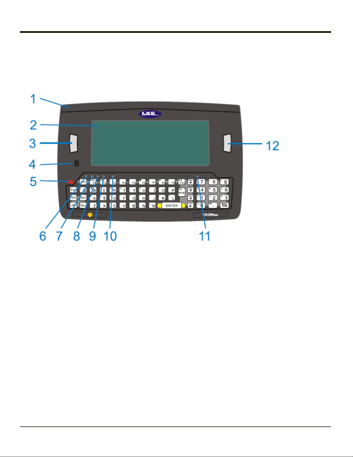
Front
1. Endcap
2. Display
3. Programmable Key
4. Beeper
5. On / Off Button
6. 2nd LED
7. Alt LED
8. Ctrl LED
9. Shift LED
10. Caps LED
11. Status LED
12. Programmable Key
1-3
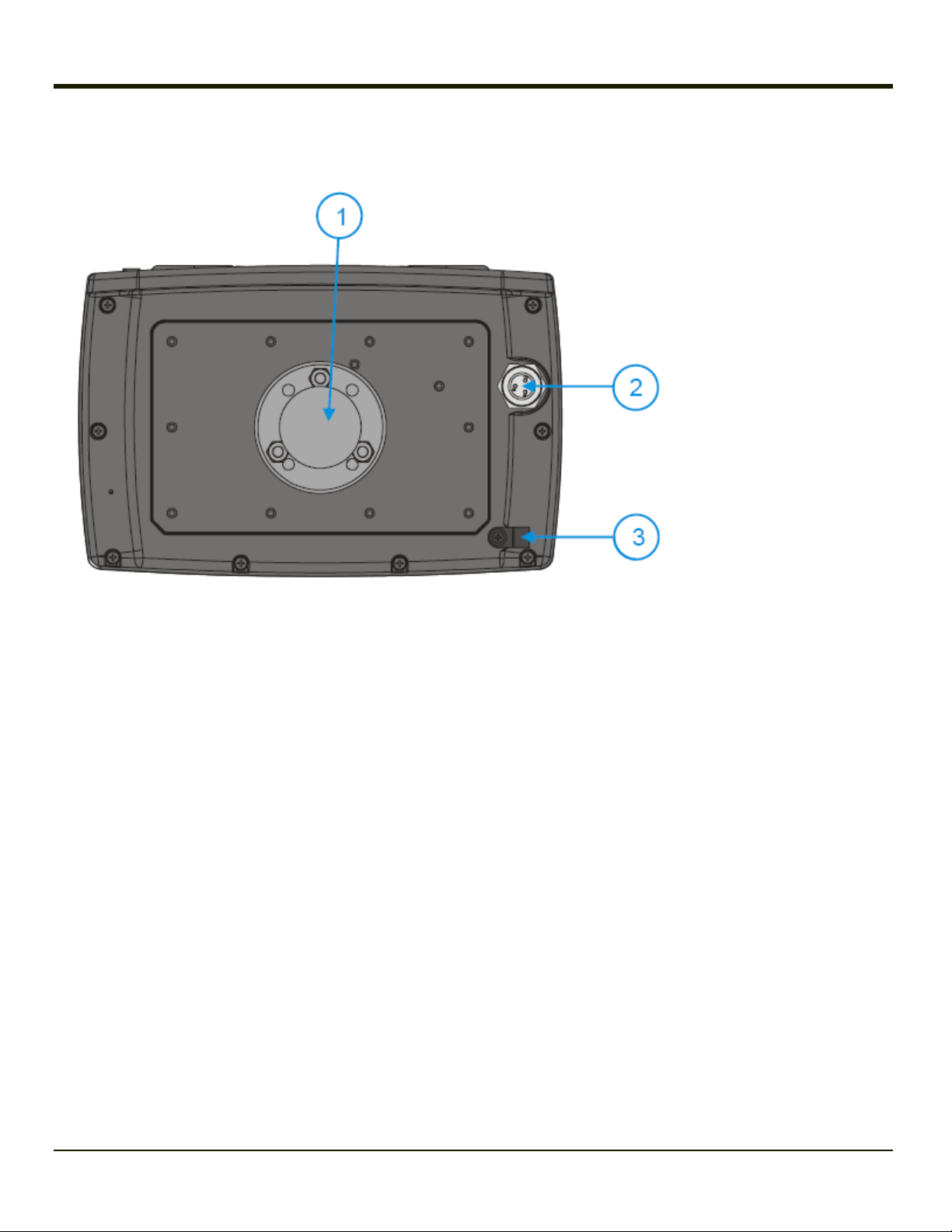
Back
1. RAM Ball
2. Power Connector
3. Strain Relief Clamp
1-4
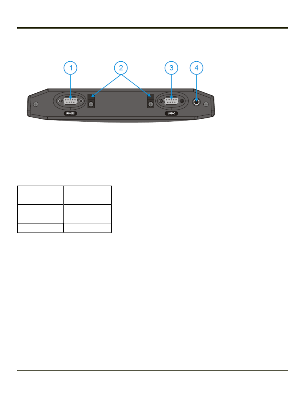
Endcap
1. Left Port
2. Cable Strain Relief Clamps
3. Right Port
4. Audio Jack or External Antenna Connector (Audio Jack shown)
Endcap Options
Left Port Right Port
COM3 (RS-232) USB-Client (USB-C)
COM3 (RS-232) COM1 (RS-232)
USB-Host (USB-H) COM1 (RS-232)
USB-Host (USB-H) USB-Client (USB-C)
VX3Plus without a Touchscreen
If your VX3Plus is not equipped with a touchscreen you can use keypad shortcuts instead of the stylus.
For a VX3Plus equipped with a touchscreen, the touchscreen can be disabled and enabled using Start > Settings > Control
Panel > MX3X-VXC Options > Misc tab.
If a touchscreen is not present or the touchscreen is disabled, it may be preferable to use ActiveSync and LXEConnect to
configure the VX3Plus.
1-5

1-6
Chapter 2: Hardware
System Hardware
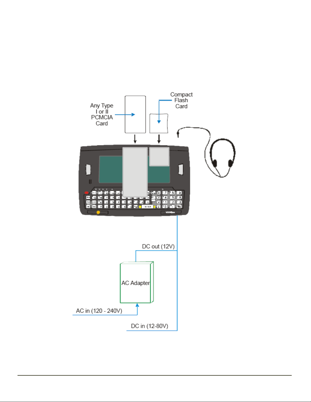
2-1

802.11b/g and a/b/g Wireless Client
The VX3Plus has an 802.11x network card that supports diversity with two internal antennas. The CPU board does not allow
hot swapping the network card. Power management for the network card is configured with the Summit Client Utility.
WEP, WPA and LEAP are supported.
Central Processing Unit
The CPU is a 400MHz Intel XScale PXA255 CPU. The operating system is Microsoft Windows CE 5.0. The OS image is
stored on an internal SD flash card and is loaded into DRAM for execution.
XScale turbo mode switching is supported and turned on by default.
The VX3Plus supports the following I/O components of the core logic:
l One PCMCIA slot (supports Type I or II PCMCIA cards).
l One CompactFlash card port.
l One Digitizer Input port (see Touchscreen).
l Two I/O ports in four configurations (see Endcap Combinations).
System Memory
A CF Card FLASH is used for ROM, Flash for Windows operating system and Flash memory for bundled applications. The
Flash is configured as the primary boot device and contains the Windows operating system image, boot loader, OAL,
applications, utilities and device drivers.
Any flash remaining beyond the Windows operating system image is formatted for use as a persistent memory drive (which
appears in My Computer as the folder labeled System). Any programs or data stored in this folder will not be lost if the memory
backup battery fails.
The computer has one Type II CF+ slot. The computer supports and auto detects up to 256MB of Type I CompactFlash
memory.
Video Subsystem
The display has a 640 pixel (horizontal) by 240 pixel (vertical) format. The display controller supports Windows CE graphics
modes. Touchscreen allows mouse functions (pointing and tapping on the display or Signature Capture) using a stylus.
There are two types of displays available:
l The active transmissive color display is optimized for indoor lighting.
l The active transflective display is optimized for outdoor viewing.
Power Supply
Vehicle power input for the VX3Plus is 12V to 80V DC nominal and is accepted without the need to perform any manual
operation within the VX3Plus.
Backup Battery
The VX3Plus has a permanent 190 mAh Lithium battery installed to maintain time, date and CMOS setup information. The
lithium battery is not user serviceable and should last five years with normal use before it requires replacement.
2-2

Note: The backup battery should only be changed by authorized service personnel.
Audio Interface
An interface is available for headset operation. When a headset is plugged into the audio jack on the endcap, the main speaker
is disabled.
PCMCIA and CF Slots
Use and operation of the Personal Computer Memory Card International Association (PCMCIA) device (e.g. PC card) is
dependent upon both the type of device installed and the application(s) running on the computer. Make sure the proper software
is pre-loaded and PC cards are properly configured.
PCMCIA – Network or SRAM Cards
When removing or installing the network card, protect the internal components and the network card from electrostatic
discharge.
The VX3Plus has one internal PCMCIA slot that conforms electrically to PCMCIA 2.1 specifications. The PC Slot supplies
0.75 of an amp at 5Volts or 3.3Volts. Battery voltage is supplied through unused pin 35 to support a WAN client device in the
slot. The PC slot is accessible by the use of a Phillips screwdriver to first loosen the endcap. It accepts Type I or II cards only.
Slot 0 accepts PCMCIA 802.11 network cards or SRAM/Flash memory cards.
CF – CompactFlash Card
The VX3Plus has one internal CompactFlash card port that supports Type I and II CF+ cards. The slot is accessible when the
endcap has been loosened.
2-3

Bluetooth LXEZ Pairing
The VX3Plus contains Bluetooth version 2.0 with Enhanced Data Rate (EDR) up to 3.0 Mbit/s over the air. Bluetooth device
connection (or pairing) can occur at distances up to 32.8 ft (10 meters) Line of Sight. The wireless client retains wireless
connectivity while Bluetooth is active.
The user will not be able to select PIN authentication or encryption on connections to from the VX3Plus. However, the
VX3Plus supports authentication requests from pairing devices. If a pairing device requests authentication or encryption, the
VX3Plus displays a prompt for the PIN or passcode. Maximum encryption is 128 bit. Encryption is based on the length of the
user’s passcode.
Bluetooth filtered mode simultaneously supports one printer as a slave Bluetooth device and one scanner, either as a slave or
as a master Bluetooth device.
l The VX3Plus does not have a Bluetooth managed LED.
l The LED on the Bluetooth scanner illuminates during a scanning operation.
l Barcode data captured by the Bluetooth scanner is manipulated by the settings in the VX3Plus Scanner Properties
control panel applet.
l Multiple beeps may be heard during a barcode scan using a mobile Bluetooth scanner; beeps from the mobile Bluetooth
scanner as the barcode data is accepted/rejected, and other beeps from the VX3Plus during final barcode data
manipulation.
See also: Start > Settings > Bluetooth
2-4

Power Modes
The VX3Plus has four power modes: On, User Idle, Suspend and Off.
On Mode
When the VX3Plus is attached to either vehicle 12-80 VDC or an external power supply and the power button is pressed, the
VX3Plus is in the On mode. In this mode, the keypad, touchscreen and any attached peripherals such as a scanner function
normally. The display remains on until the backlight timer (if enabled) expires.
User Idle Mode
If the Display Backlight Timer is enabled (Start > Settings > Control Panel > Display), the VX3Plus enters User Idle Mode
when the display backlight timer expires without any Primary Event (see below) to reset the timer. The VX3Plus exits User Idle
Mode with any Primary Event.
The keypress or screen touch that exits User Idle Mode is sent to the operating system.
The VX3Plus then transitions to On Mode.
Primary Events
l Any key on the keypad
l COM1 activity
l Stylus touch on the touchscreen
l Scanner activity
l Power button tap
l USB client connection
l Bluetooth device reconnect / disconnect message
Suspend Mode
The Suspend mode is entered when the Power Button is tapped. Some devices may include a Start > Suspend option to enter
Suspend mode.
In Suspend mode, the display is off. Any of the events listed below wakes the VX3Plus from Suspend and returns the VX3Plus
to On mode.
The keypress or screen touch that exits Suspend Mode is not sent to the operating system.
Any of the following primary events will wake the unit and reset the display / display backlight timers:
l Any key on the keypad
l Power button tap
l Stylus touch on the touchscreen
l Bluetooth device reconnect / disconnect message
2-5

Off Mode
The VX3Plus enters the Off Mode when it is not connected to a power source. However, an internal Real Time Clock (RTC)
powered by an internal battery maintains the date and time while the VX3Plus is off.
2-6
External Connectors
Most external connectors for the VX3Plus are located on the top of the unit.
l The RS-232 port, if present, (COM1 or COM3) connects to a serial barcode scanner, PC or printer.
l The USB-C port, if present, provides a USB Client connection.
l The USB-H port, if present, provides a USB Host connection.
l Audio connects to a mono or stereo telephone headset/microphone.
l An optional connector for a remote mount antenna.
When the remote antenna mount is ordered, the VX3Plus does not have an audio connector.
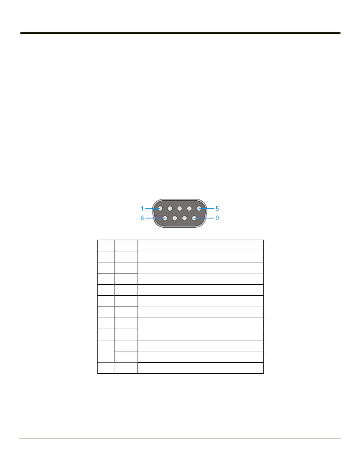
RS-232 Connector (COM1 or COM3)
When present, the serial connector, labeled “RS-232”, (configured as COM1 or COM3 depending on endcap option selected) is
industry-standard RS-232. The connector includes a PC/AT standard 9–pin “D” male connector. By default, Pin 9 to provide RI.
Pin 9 of COM1 or COM 3 may also be configured to supply +5 VDC at 0.4A (max) for an external bar code scanner.
Power the VX3Plus off before attaching a cable or device to the COM1 or COM3 serial port.
Pin Signal Description
1 DCD Data Carrier Detect - Input
2 RXD Receive Data - Input
3 TXD Transmit Data - Input
4 DTR Data Terminal Ready - Input
5 GND Signal/Power Ground
6 DSR Data Set Ready - Input
7 RTS Request to Send - Output
8 CTS Clear to Send - Input
+5VDC Bar Code Scanner Power - 400mA max (default)
9
RI Ring Indicator
Shell CGND Chassis Ground
Technical Specifications - Connection Cable
The exact serial cable is crucial. Many commercial null modem cables will not work. The following cable is recommended:
Serial Cable - 9000060CABLE
2-7
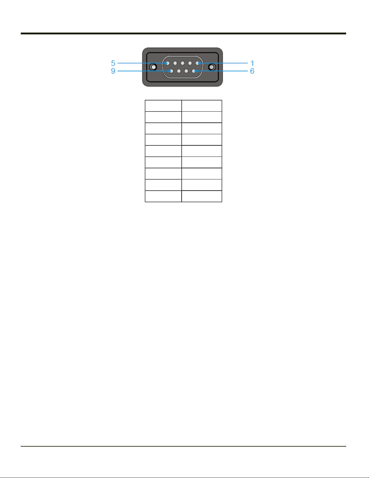
DB9 female DB9 female
1 7
2 3
3 2
4 6, 8
5 5
6, 8 4
7 1
9 no connection
Some laptop devices do not properly implement all control lines on the serial port - the laptop connection will not work.
RTS/CTS Handshaking and the Serial Port
RTS Ready to Send
CTS Clear to Send
DTR Data Terminal Ready
DSR Data Set Ready
Remote Side The device sending data to and receiving data from the VX3Plus through the serial cable connected to the RS-
232 ports on both devices.
Serial Cable: 9000060CABLE
The VX3Plus serial port supports four types of handshaking via the serial cable: None, standard Xon/Xoff, standard
DTR/DSR, and a form of RTS/CTS.
To use RTS/CTS, the remote side computer must clear the DTR line which sets the VX3Plus CTS line and allows the
VX3Plus to send data to the remote side.
And then signals and data travel smoothly between both devices.
2-8
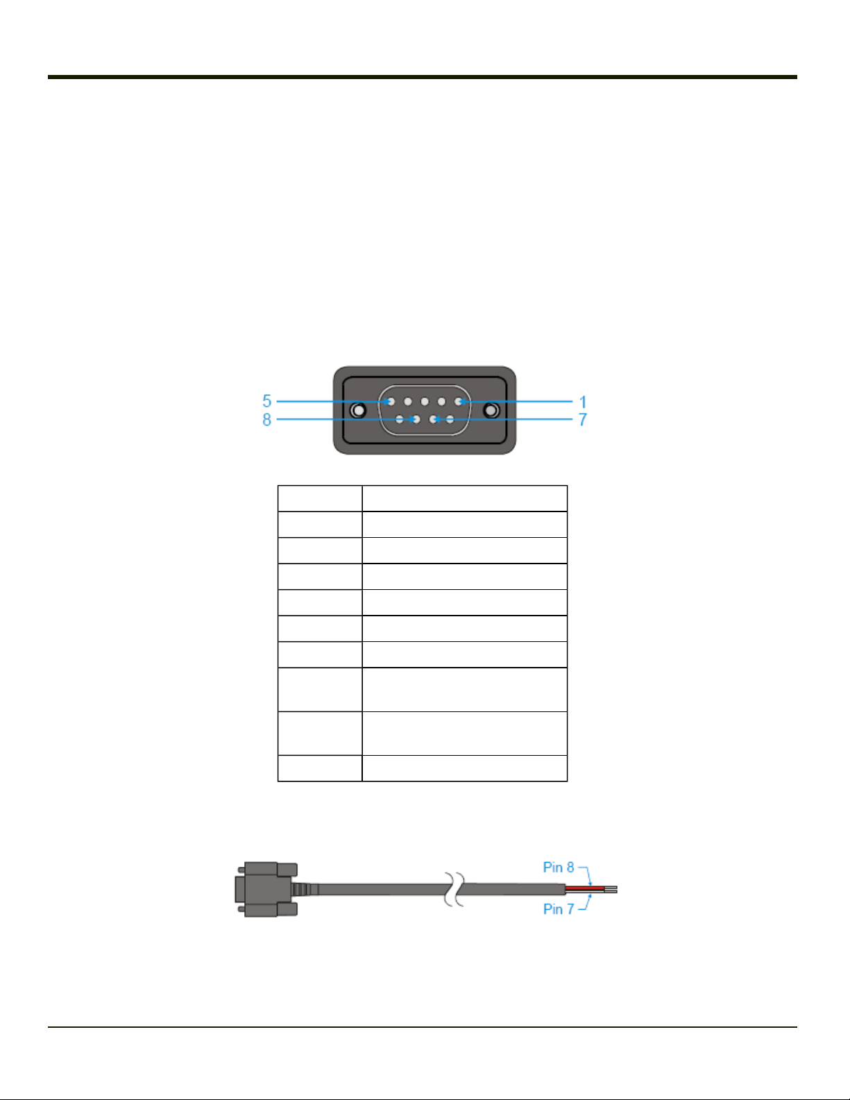
Screen Blanking Cable
The customer must supply their own cable.
The cable must be designed so that pin 7 (RTS – Request to Send Output) and pin 8 (Clear to Send Input) of a D9 female
connector provide continuity only when the vehicle is stopped (for example, via a switch on the accelerator pedal of the fork
truck).
All other pins on the connector must be left unconnected. If pins 7 and 8 do not provide continuity (or the cable is removed), the
VX3Plus screen remains blank.
Serial Cable
Customer built cable with the following specifications.
DB9 female Function
1 Not Used
Sample Cable for Screen Blanking
2 Not Used
3 Not Used
4 Not Used
5 Not Used
6 Not Used
7
8
9 Not Used
No signal when in motion,
Continuity to Pin 8 when stopped
No signal when in motion,
Continuity to Pin 7 when stopped
Proper COM port settings to support screen blanking are located in Start > Settings > Control Panel > Scanner.
2-9
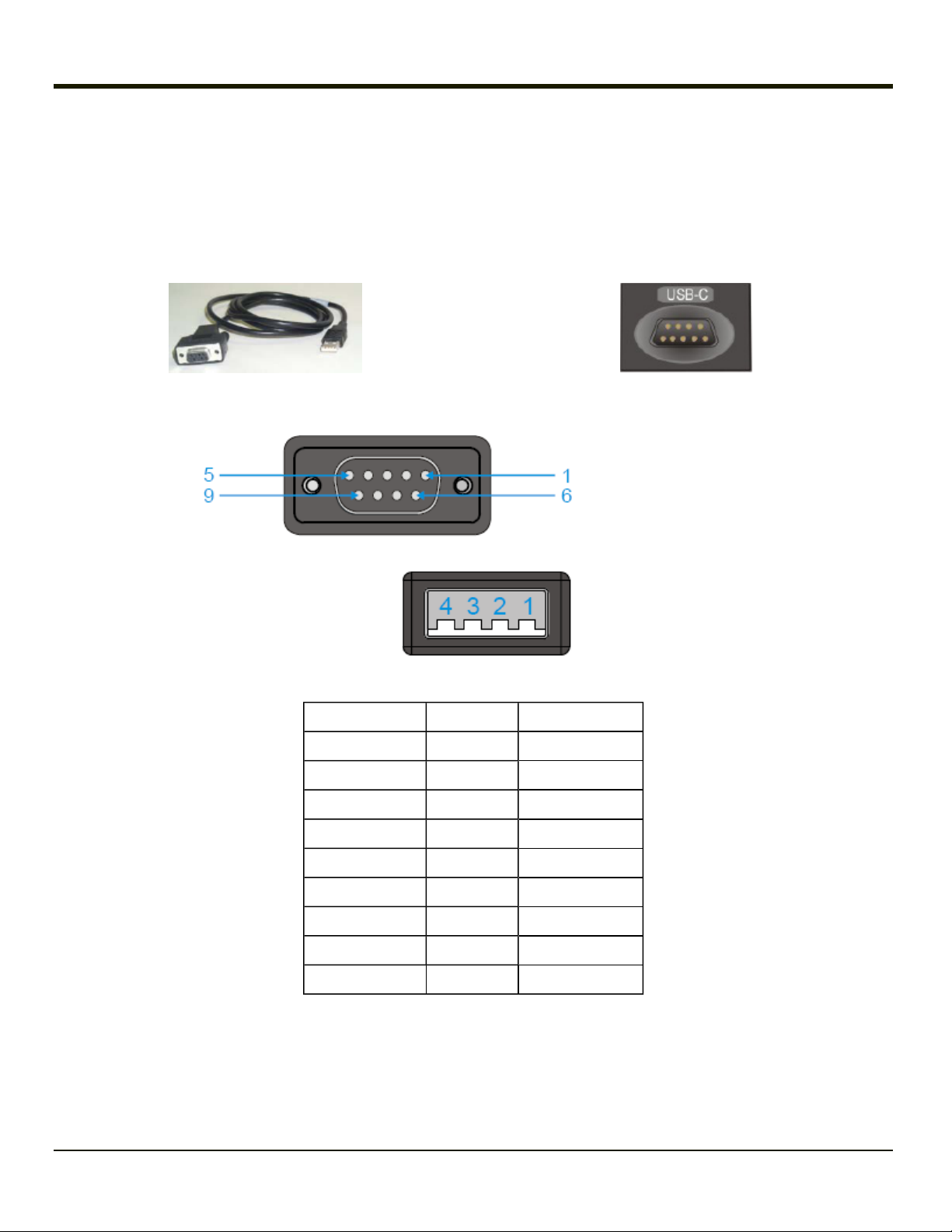
USB-C Connector
When present, the USB client connector (labeled “USB-C”) is an industry-standard RS-232 9-pin “D” male connector.
The optional USB cable is required to adapt the connection to a standard USB connector.
Caution: Do not use the USB labeled endcap port for tethered scanners or other serial devices.
USB Client Cable USB Client Port on Endcap
ActiveSync : Connect from USB-C port to USB Type A Host – a laptop/desktop, etc.
VX3Plus DB9 Connector
USB Client Connector
DB9 Connector Signal USB Connector
1 Host Detect 1
2 Not Used
3 D+ 3
4 Not Used
5 Ground 4
6 Not Used
7 D- 2
8 Not Used
9 Not Used
2-10
 Loading...