

Page 1
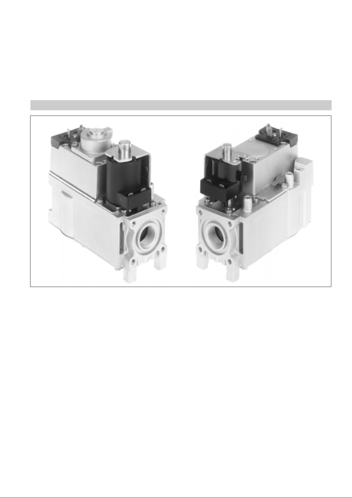
VR46../VR86.. series
COMPACT AUTOMATIC COMBINATION GAS CONTROLS
PRODUCTHANDBOOK
APPLICATION
The Compact Automatichas been specially developed for application in domestic central heating boilers, warm air furnaces or
water heatergas appliances.
The Compact Automaticisusedina systemcontextin conjunction with either a direct spark ignition(DSI),intermittent pilot (IP)
or Hot Surface Ignition control module and associated devices to provide programmed safe light--up and supervision of the main
burner of an appliance.
Subject to change without notice. Printed in the Netherlands.
EN2R--9003 9510R2--NE
Page 2

CONTENTS
General
Description 3...................................................................................................
Feature 4......................................................................................................
Technical
Specifications 5.................................................................................................
Capacity 6.....................................................................................................
Capacity curve C90 8............................................................................................
Capacity curve C100 9...........................................................................................
Capacity curve C110 10..........................................................................................
Capacity curve C120 11..........................................................................................
Capacity curve C130 12..........................................................................................
Capacity curve C170 13..........................................................................................
Capacity curve C200 14..........................................................................................
Capacity curve C210 15..........................................................................................
Capacity curve C220 16..........................................................................................
Capacity curve C230 17..........................................................................................
Capacity curve C240 18..........................................................................................
Capacity curve C250 19..........................................................................................
Capacity curve C260 20..........................................................................................
Capacity curve C270 21..........................................................................................
Capacity curve F20 22...........................................................................................
Capacity curve F30 23...........................................................................................
Capacity curve F40 24...........................................................................................
Capacity curve F50 25...........................................................................................
Electrical data low voltage 26.....................................................................................
Electrical data line voltage 27.....................................................................................
Performancecharacteristics 28....................................................................................
Dimensional drawing VR46../VR86..A/C, AB/CB 30...................................................................
Dimensional drawing VR46../VR86..B/D 31.........................................................................
Dimensional drawing VR46../VR86..A/C, AA/CA, AB/CB, VA 32........................................................
Dimensional drawing VR46../VR86..E/T,EA/TA 33...................................................................
Installation
Installation 34...................................................................................................
Adjustmentsand final checkout 35.................................................................................
Construction and working principles 36.............................................................................
Various
Qualityassurance statement 39...................................................................................
Approvals and standards 40......................................................................................
Ordering information 41..........................................................................................
2
EN2R--9003 9212R2--NE
Page 3

DESCRIPTION
Compact Automatic combination gas controls performall the
functions required to safely regulate gas flow to the pilot
burner and the main burner of domestic central heating
equipment,warm air furnaces, back boilers and water
heaters.
Compact Automatic combination gas controls comprise a
standard body to which a range of sub--assemblies are
factoryfitted to give various system options. This makes boiler
system design much easier as technical s pecifications and
unit dimensions are the same for all system options. Options
include servo pressure regulation,throttle valve, (switchable)
softlite, electricalhigh--low control and electricalor mechanical
modulationfor the complete range of control applications.
Compact Automatic combination gas controls are available in
line or low voltage versions and in three capacity ratings for
totalsystem versatility. Customer specific voltage models are
also offered
Compact Automatic combination gas control consist of a first
direct electric on/off operator for opening the safety valve of
class A or class B according to EN 161 and a second electric
on/offservo operatorvalve for opening the main valve of class
B, C or class D according to EN 161 and comply with the
additionalrequirementof D’ valves according to EN 297.
Compact Automatic combination gas controls are rated for
gas families MFD Group A (G 110), MFD Group B (G 120),
NaturalH (G 20), NaturalL (G 25) and LP (G 30).
All measurements are carried out under standard c onditions,
unless otherwise is indicated.
Standardconditions
• P
• P
• T
• Outletorifice 2.8 mm
• Flow indication in m
• Recording of outlet pressure with a transducer connected
25 mbar nominal pressure, dry air of 20EC
inlet
1013 mbar
ambient
20EC
ambient
3
/
h
1
to a
/2” pipe with a length of 10 d with a short hose
at 5 d.
• Nominal voltage
• Upright position, i.e. the position when the operators are on
top.
3
EN2R--9003 9212R2--NE
Page 4

FEATURES
General
:
Specially designed for use with gas appliances with a DSI,
HSI or IP system to light the main burner.
:
Incorporates time proven design concepts assuring
reliability.
:
ON/OFF control of main burner by electric on/off operator
and electricon/off servo operator.
:
At inlet side an internal fine mesh screen is incorporated in
the Compact Automatic. This screen is not intended to be
removable for cleaning. When flanges are used, removable
screens can be placed between the flanges and the
Compact Automatic.
:
Outletscreen (optional).
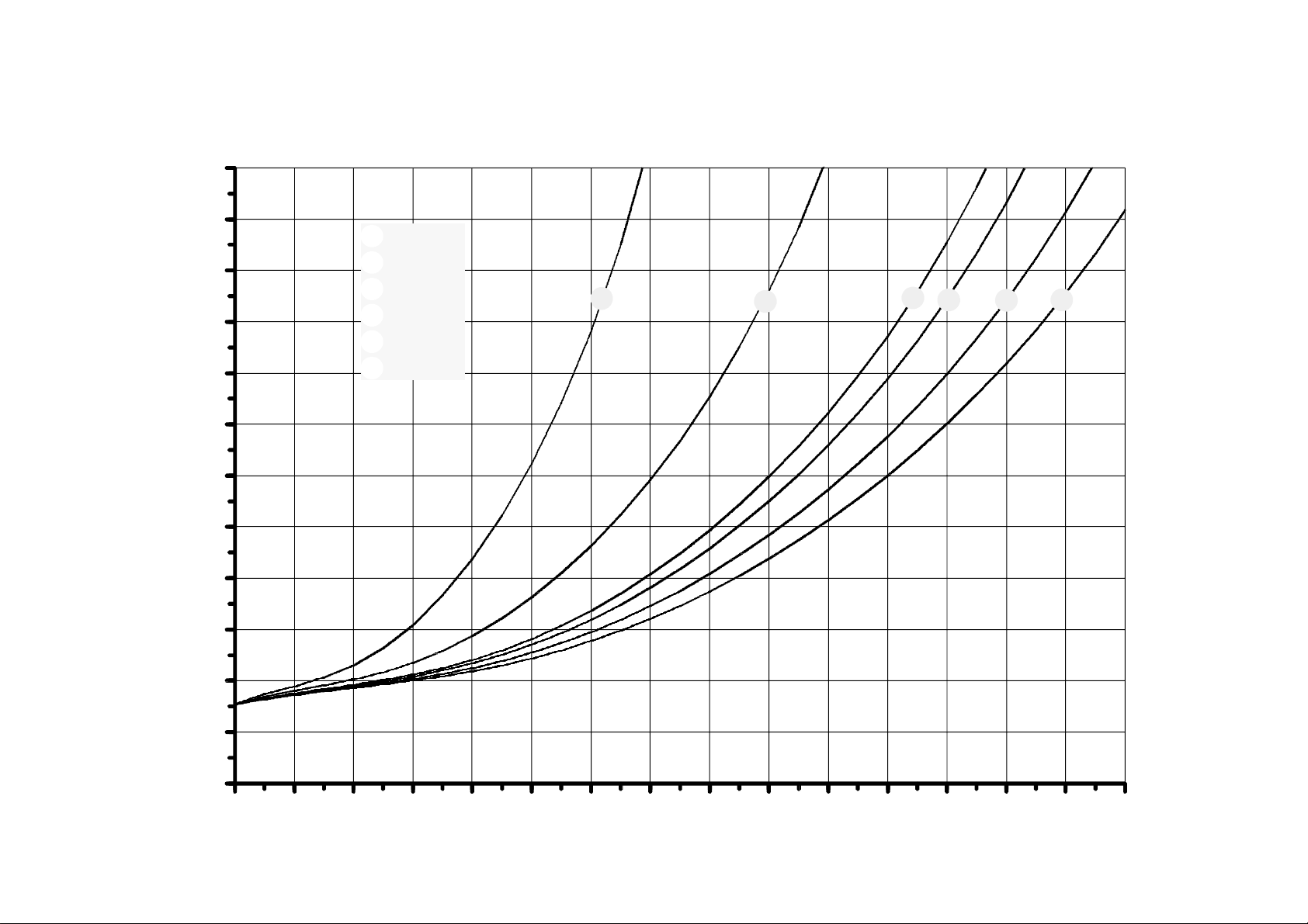
:
Various closing force models are available: B + B, B + D,
B+C,A+DandA+C.
:
All adjustments are located on the top of the Compact
Automatic.
:
9 mm outer diameter pressure tap at inlet and outlet side for
checking and adjusting burner pressure.
:
A wrench boss is incorporatedat the inlet side of the
Compact Automatic for pipe fitting.
:
Compact Automatic mounting orientation may be within 90
in any directionfrom the electric on/off operator upright
position.
:
Twothreaded mounting holes are at the bottom of the
Compact Automatic for rigid attachment to the appliance.
:
Main valve on/off servo operator with DIN faced electrical
connection has two threaded holes at the top for mounting
purposes (e.g. cover).
:
High, medium and low capacity models are available.
:
Main valve on/off servo operator employs DIN face
electrical connection which are also suitable for AMP
connections.
:
The coil of the electric on/off operatoris field replacable and
can also be positioned in other directions for better
accessability.
Gasconnectionoptions
:
Inlet and outlet connections are straight through and
threaded (standard model).
:
Inlet and outlet connections can receive flanges.
:
Side outlet options are available for both main and pilot gas.
:
The pilot gas connection for using break away connectors
for various O.D. tubing is located at the outlet end of the
Compact Automatic (standard model).
:
The pilot gas side outlet and special end outlet are suitable
for manifold connections.
:
High capacity model has straight through inlet and outlet
with Ø 23 mm bore.
Electricalconnection options
:
Both top face and bottom face AMP electrical connection
on electricon/off operator are available.
:
Single plugs are available with cable and strain reliefin
several versions (IP 40)
:
Seperate plugs on first and second electric on/off operator
are available (IP 40).
:
IP 44 connection by means of two DIN connectors is
possible.
:
Quick connect 6,3 mm fastons on both coils can be applied
in combination with single cover or separate covers with
E
strain relief.
:
Line voltage on/off servo operators are provided with a
ground screw and washer.
Functionaloptions
:
Servo pressure regulator provides stable outlet pressure.
:
Pressure feedback ensures constant burner
pressure(optional).
:
A throttle valve version is available,where unregulated
valves may be employed.
:
Softlite option to facilitate a smooth light up of burners.
:
Switchable softliteoption for changing over from one gas to
another and vice versa.
:
Electrical or mechanical modulation.
:
ElectricalHigh--Low control.
:
Incorporated pilot filter(optional).
:
Pilot outlet for IP system.
:
Suitable for use with Gas/Air ratio components.
4
EN2R--9003 9212R2--NE
Page 5

SPECIFICATIONS
NOTE: Specificationsfor electrical modulation,
mechanical modulation, electrical high low,
switchable softliteand other features are
available on request.
Models
See model number chart on page 41
Pipe sizes
• Inlet and outlet
• Inlet 18,6 mm dia and outlet
pipe thread
• Inlet
1
/2” ISO 7/1 internal parallel pipe thread and outlet
1
/2” ISO 7/1 internal parallel pipe thread.
1
/2” ISO 7/1 internalparallel
18,6 mm dia
• Inlet and outlet Ø 23 mm bore (high capacity models only)
• Inlet and outlet can also be fitted with straightor elbow
flanges.
• Side outlet (optional)can only be fitted with a flange.
Ambient temperature
VR46../VR86..xA: 0 ... 70
VR46../VR86..x: 0 ... 60
VR46../VR86..xB: 0 ... 60
E
C
E
C
E
C
Pilotgas connection
Standard at end outlet:
M11x1for
1
/4”, 6 mm or 4 mm O.D. tubing.
Special connection:
Incorporated in the side outlet.
Pressure feedback connection
The servo pressure regulator has an M5 thread connection for
pressure feedback.
Enclosure
IP 40 with covers or plugs
IP 44 with DIN plugs according to DIN 43650
Dimensions
See Dimensional drawing
Maximum operating pressure
The P
indicationon the housing of the Compact
max
Automaticis the maximum pressure at which it functions
safely. However, the maximum operating pressure is limited
by the pressure range of the pressure regulator concerned
(see table 1.).
Table 1. Maximum operating pressure
Model
Pressure range
(mbar)
Maximum
operating
pressure (mbar)
with regulation 2.5 ... 20 30
3 ... 37* 45
5 ... 50* 60
10 ... 60* 100
without
-- 60
regulation
with throttle -- 60
* This type can also be used for non regulation mode in LP
applicationswhen pressure regulatoradjustment screw is
clockwise turned down until it stops.
Mountingholes
TwoM5 mounting holes are located on the bottom of the
Compact Automatic.
The four holes at inlet and outlet for mounting the flange on
the Compact Automatic are provided with M5 thread with min.
6.5 mm full thread.
The four holes for mounting the flange to the side outlet are
provided with M4 thread with minimum 6 mm full thread.
TwoM4 threaded holes on DIN faced electrical on/off servo
operatorare also for mounting purposes.
Minimumregulation capacity
3
0.31 m
/h
Minimumadjustable capacity (throttlevalve only)
0.6 m3/h air at ∆P of 20 mbar
3
Minimumdifferentialpressure at 0,31 m
Model*
/hair
∆Pmin(mbar)
VR4601/VR8601XA 1.8
VR4605/VR8605XA 1.8
VR4611/VR8611XA 3.9
VR4615/VR8615XA 3.9
VR4621/VR8621XA 3.9
VR4625/VR8625XA 3.9
VR4631/VR8631XA 1.8
VR4635/VR8635XA 1.8
VR4641/VR8641XA 3.9
VR4645/VR8645XA 3.9
VR4601/VR8601X 1.7
VR4605/VR8605X 1.7
VR4611/VR8611X 3.9
VR4615/VR8615X 3.9
VR4621/VR8621X 3.9
VR4625/VR8625X 3.9
VR4631/VR8631X 1.7
VR4635/VR8635X 1.7
VR4641/VR8641X 3.9
VR4645/VR8645X 3.9
VR4601/VR8601XB 1.7
VR4605/VR8605XB 1.7
VR4611/VR8611XB 3.9
VR4615/VR8615XB 3.9
VR4621/VR8621XB 3.9
VR4625/VR8625XB 3.9
VR4641/VR8641XB 3.9
* X = suffix letter
5
EN2R--9003 9212R2--NE
Page 6

CAPACITY IN m3/hAIR ATPRESSURE DROPAS SHOWN.
(mm)
(mm)
(mbar)
(
3
/h)
SEE ALSO THE CORRESPONDING CAP ACITY CURVES
Safety valve Main valve
Model Remark Class Seat
VR460.XA
Standard B 11 D 17 C110 2.5 1.95
VR860.XA
VR460.XA
Upgraded B 17 D 17 C210* 3 2.7
VR860.XA
VR460.XA
Standard B 11 D 17 C220* 2.5 1.4
VR860.XA
VR461.XA
Standard B 11 C 17 C120 5 1.8
VR861.XA
VR461.XA
Upgraded B 17 C 17 C230* 5 2.5
VR861.XA
VR462.XA
Standard B 11 B 17 C240* 5 2
VR862.XA
VR462.XA
Upgraded B 17 B 17 C250* 5 2.5
VR862.XA
VR463.XA
Standard A 11 D 17 C110 2.5 1.95
VR863.XA
VR464.XA
Standard A 11 C 17 C120 5 1.8
VR864.XA
VR461.VA
Standard B 11 C 11 F40 10 4.1
VR861.VA
VR464.VA
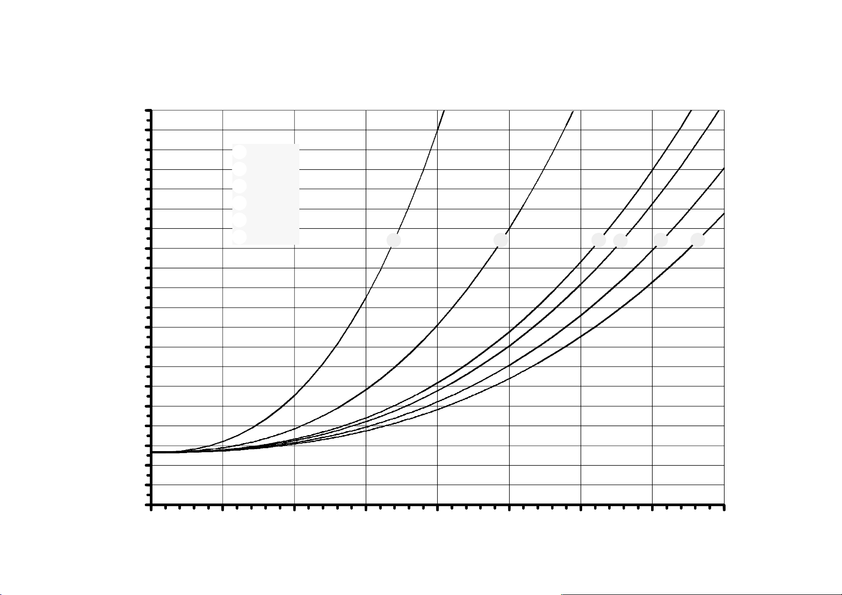
Standard A 11 C 11 F20 10 4.1
VR864.VA
VR461.V
Standard B 17 C 11 F30 10 5.1
VR861.V
VR464.V
Standard A 17 C 11 F50 10 5.1
VR864.V
VR460.X
Standard B 17 D 17 C90 3 3.1
VR860.X
VR461.X
Standard B 17 C 17 C100 5 3
VR861.X
VR462.X
Standard B 17 B 17 C260* 5 3
VR862.X
VR463.X
Standard A 17 D 17 C90 3 3.1
VR863.X
VR464.X
Standard A 17 C 17 C100 5 3
VR864.X
VR460.XB
Standard B 18.5 D 17 C130 3 4.2 23 mm 23 mm
VR860.XB
VR461.XB
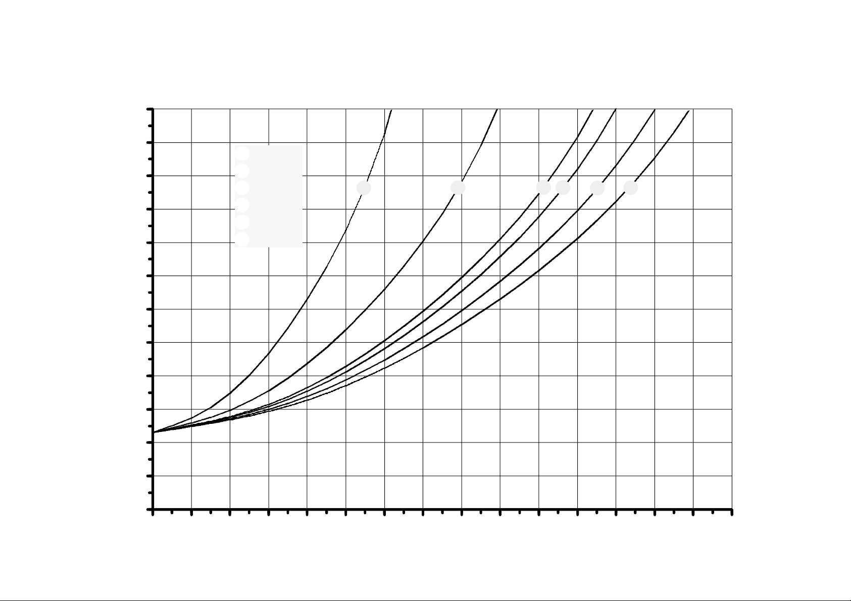
Standard B 18.5 C 17 C170 5 4.6 23 mm 23 mm
VR861.XB
* Capacity curve to be specified
Class Seat
Capacity
curve
number
∆P
Capacity3Inlet Outlet
m
Straight Side
1
/2”
1
/2”
1
/2” Flange
1
/2”
1
/2”
1
/2”
1
/2”
1
/2”
1
/2”
1
/2”
1
/2”
1
/2”
1
/2”
1
/2”
1
/2”
1
/2”
1
/2”
1
/2”
1
/2”
1
/2”
1
/2”
1
/2”
1
/2”
1
/2”
1
/2”
1
/2”
1
/2”
1
/2”
1
/2”
1
/2”
1
/2”
1
/2”
1
/2”
1
/2”
1
/2”
6
EN2R--9003 9212R2--NE
Page 7

CAPACITY IN m3/hAIR ATPRESSURE DROPAS SHOWN.
(mm)
(mm)
(mbar)
(
3
/h)
SEE ALSO THE CORRESPONDING CAP ACITY CURVES
Safety valve Main valve
Model Remark Class Seat
VR460.EB
VR860.EB
VR460.TB
VR860.TB
VR461.EB
VR861.EB
VR461.TB
VR861.TB
* Capacity curve to be specified
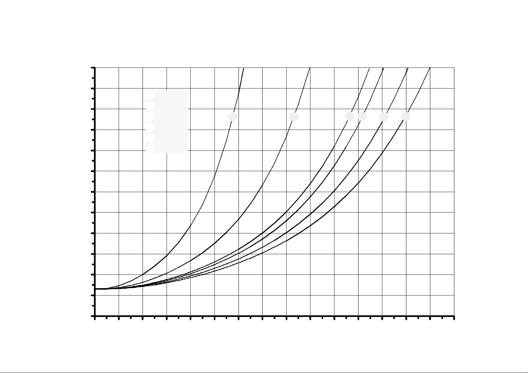
Standard B 18.5 D 17 C200 3 4.2 23 mm 23 mm
Standard B 18.5 D 17 C200 3 4.2 23mm 23 mm
Standard B 18.5 C 17 C270* 5 4.0 23 mm 23 mm
Standard B 18.5 C 17 C270* 5 4.0 23 mm 23 mm
Class Seat
Capacity
curve
number
∆P
Capacity3Inlet Outlet
m
Straight Side
7
EN2R--9003 9212R2--NE
Page 8

12
CAPACITY CURVE C90
11
10
9
8
7
8
6
5
Pressure drop (mbar)
4
3
1
2
3
4
5
6
G30
Air
G25
G20
G 140
G 110/120
1
2
3
4
5
6
2
EN2R--9003 9212R2--NE
1
0
012345
Flow (m /h at 1013 mbar and 15 C, dry)
3
E
67
Page 9
12
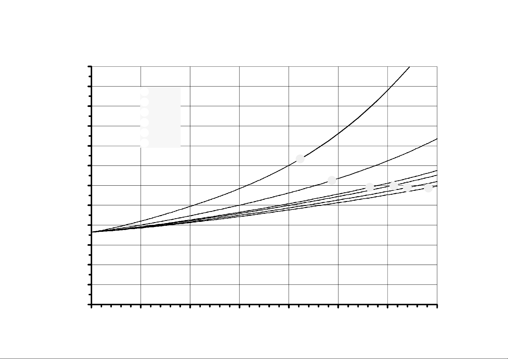
CAPACITY CURVE C100
11
10
9
8
7
9
6
5
1
2
3
4
5
6
G30
Air
G25
G20
G 140
G 110/120
1
2
3
4
5
6
Pressure drop (mbar)
4
3
2
EN2R--9003 9212R2--NE
1
0
012345
Flow (m /h at 1013 mbar and 15 C, dry)
3
E
67
Page 10
12
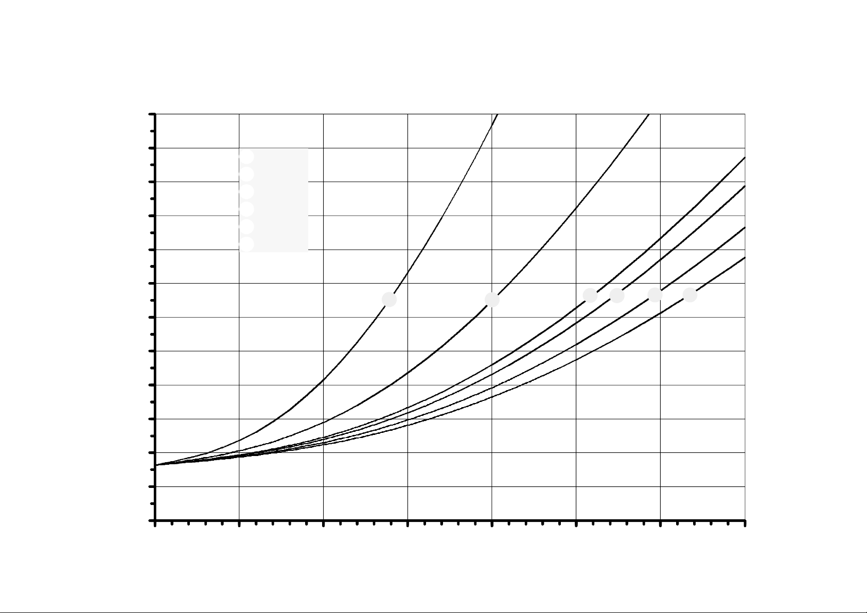
CAPACITY CURVE C110
10
11
10
9
8
7
6
5
Pressure drop (mbar)
4
3
1
2
3
4
5
6
G30
Air
G25
G20
G 140
G 110/120
4
1
2
3
5
6
2
EN2R--9003 9212R2--NE
1
0
012345
Flow (m /h at 1013 mbar and 15 C, dry)
3
E
67
Page 11
12
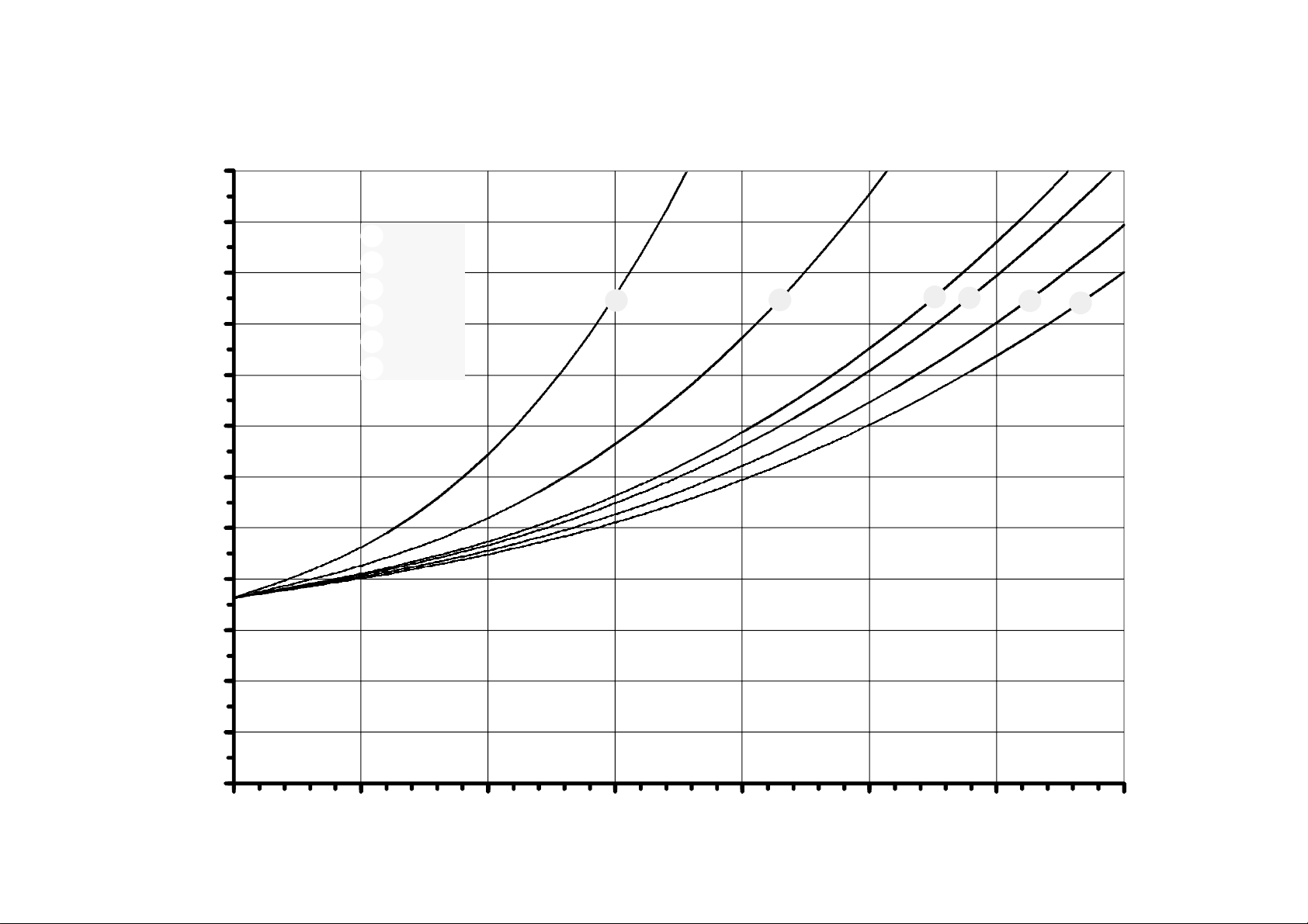
CAPACITY CURVE C120
11
10
9
8
7
11
6
5
1
2
3
4
5
6
G30
Air
G25
G20
G 140
G 110/120
1
2
364
5
Pressure drop (mbar)
4
3
2
EN2R--9003 9212R2--NE
1
0
012345
Flow (m /h at 1013 mbar and 15 C, dry)
3
E
67
Page 12
12
11
10
CAPACITY CURVE C130
G30
1
Air
2
3
G25
G20
9
8
7
4
5
6
G 140
G 110/120
1
2
3
5
64
12
EN2R--9003 9212R2--NE
6
5
Pressure drop (mbar)
4
3
2
1
0
012345
Flow (m /h at 1013 mbar and 15 C, dry)
3
67
8 9 10 11 12
E
13 14 15
Page 13
12
11
10
CAPACITY CURVE C170
G30
1
Air
2
3
G25
G20
9
8
7
4
5
6
G 140
G 110/120
1
2
4
3
5
6
13
EN2R--9003 9212R2--NE
6
5
Pressure drop (mbar)
4
3
2
1
0
012345
Flow (m /h at 1013 mbar and 15 C, dry)
3
67
8 9 10 11 12
E
13 14 15
Page 14
12
11
10
CAPACITY CURVE C200
G30
1
Air
2
3
G25
G20
9
8
7
4
5
6
G 140
G 110/120
1
2
4
3
5
6
14
EN2R--9003 9212R2--NE
6
5
Pressure drop (mbar)
4
3
2
1
0
012345
Flow (m /h at 1013 mbar and 15 C, dry)
3
67
8 9 10 11 12
E
13 14 15
Page 15

CAPACITY CURVE C210
Capcity curve C210to be specified
15
EN2R--9003 9212R2--NE
Page 16

CAPACITY CURVE C220
Capcity curve C220to be specified
16
EN2R--9003 9212R2--NE
Page 17

CAPACITY CURVE C230
Capcity curve C230to be specified
17
EN2R--9003 9212R2--NE
Page 18

CAPACITY CURVE C240
Capcity curve C240to be specified
18
EN2R--9003 9212R2--NE
Page 19

CAPACITY CURVE C250
Capcity curve C250to be specified
19
EN2R--9003 9212R2--NE
Page 20

CAPACITY CURVE C260
Capcity curve C260to be specified
20
EN2R--9003 9212R2--NE
Page 21

CAPACITY CURVE C270
Capcity curve C270to be specified
21
EN2R--9003 9212R2--NE
Page 22
20
19
CAPACITY CURVE F20
22
18
17
16
15
14
13
12
11
10
9
8
Pressure drop (mbar)
7
6
5
4
1
2
3
4
5
6
G30
Air
G25
G20
G 140
G 110/120
1 2
364
5
3
EN2R--9003 9212R2--NE
2
1
0
012345
Flow (m /h at 1013 mbar and 15 C, dry)
3
E
67
8
Page 23
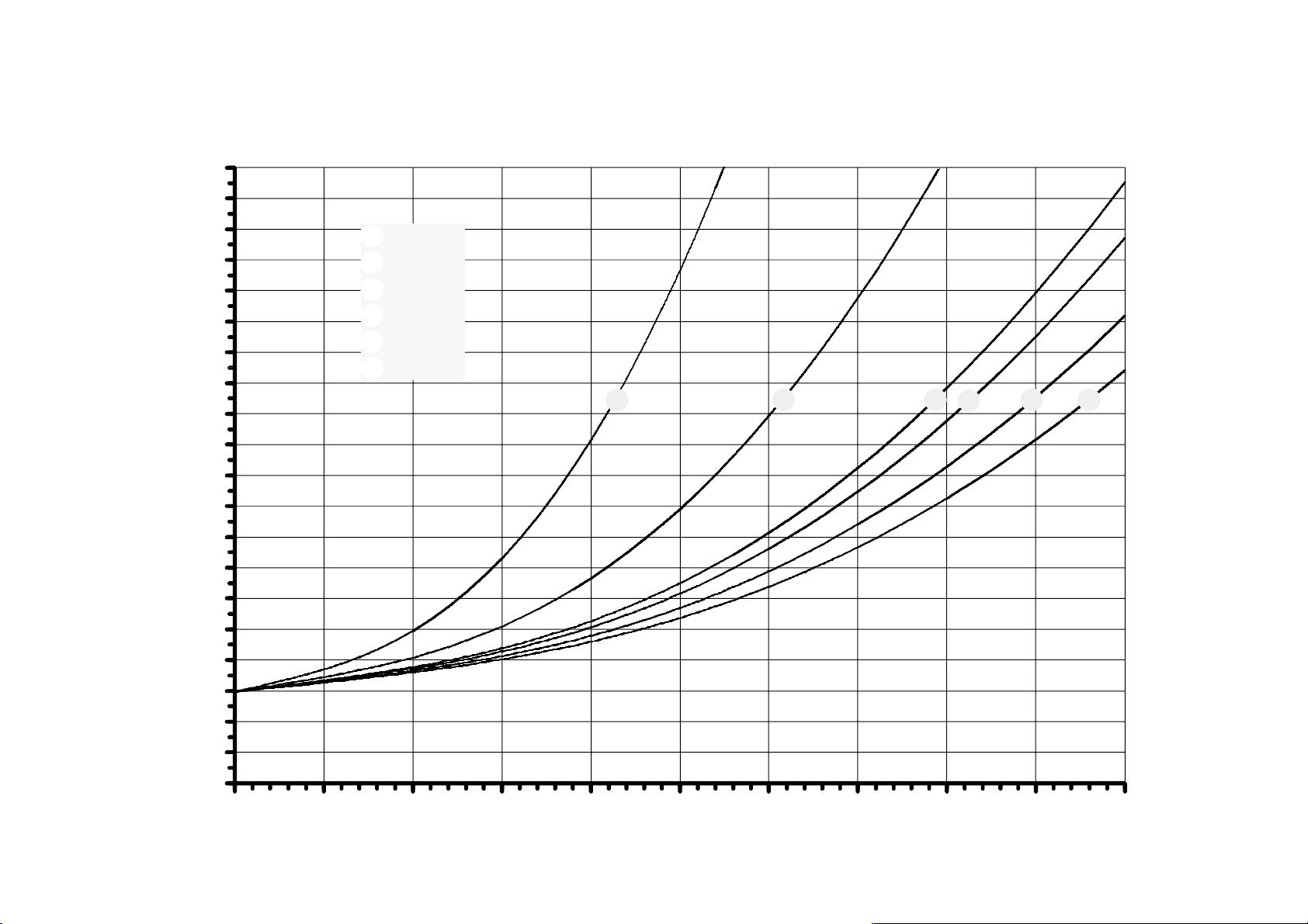
20
19
CAPACITY CURVE F30
23
18
17
16
15
14
13
12
11
10
9
8
Pressure drop (mbar)
7
6
5
4
1
2
3
4
5
6
G30
Air
G25
G20
G 140
G 110/120
1 2
364
5
3
EN2R--9003 9212R2--NE
2
1
0
012345
Flow (m /h at 1013 mbar and 15 C, dry)
3
67
E
8910
Page 24
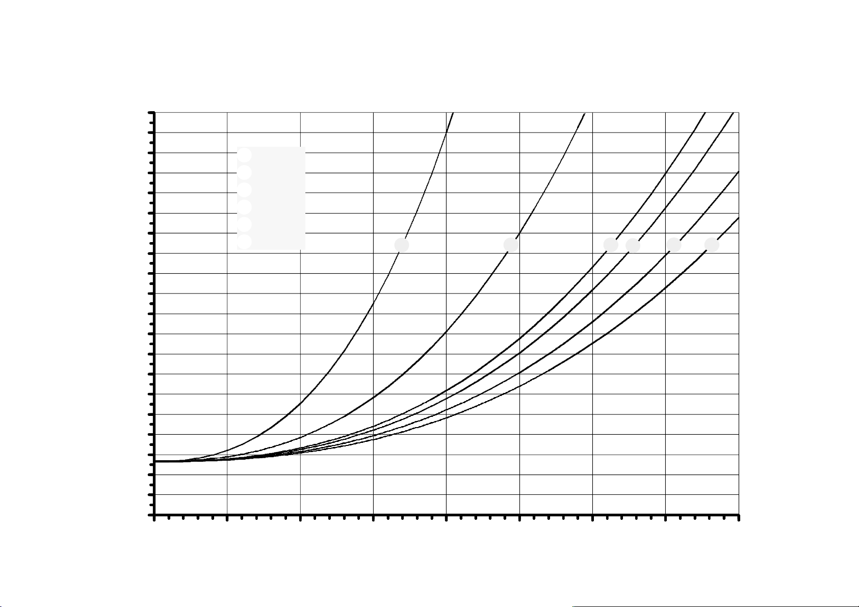
20
19
CAPACITY CURVE F40
24
18
17
16
15
14
13
12
11
10
9
8
Pressure drop (mbar)
7
6
5
4
1
2
3
4
5
6
G30
Air
G25
G20
G 140
G 110/120
1 2
364
5
3
EN2R--9003 9212R2--NE
2
1
0
012345
Flow (m /h at 1013 mbar and 15 C, dry)
3
E
67
8
Page 25
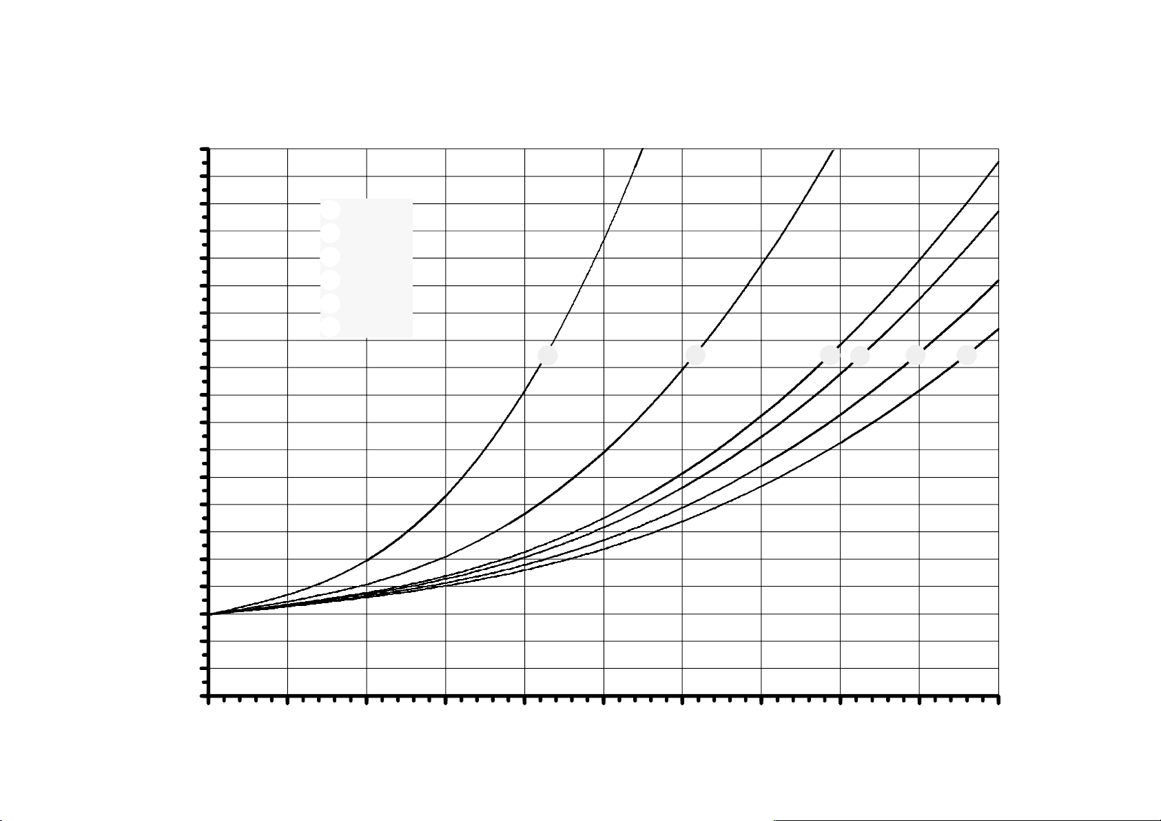
20
19
CAPACITY CURVE F50
25
18
17
16
15
14
13
12
11
10
9
8
Pressure drop (mbar)
7
6
5
4
1
2
3
4
5
6
G30
Air
G25
G20
G 140
G 110/120
1 2
364
5
3
EN2R--9003 9212R2--NE
2
1
0
012345
Flow (m /h at 1013 mbar and 15 C, dry)
3
67
E
8910
Page 26
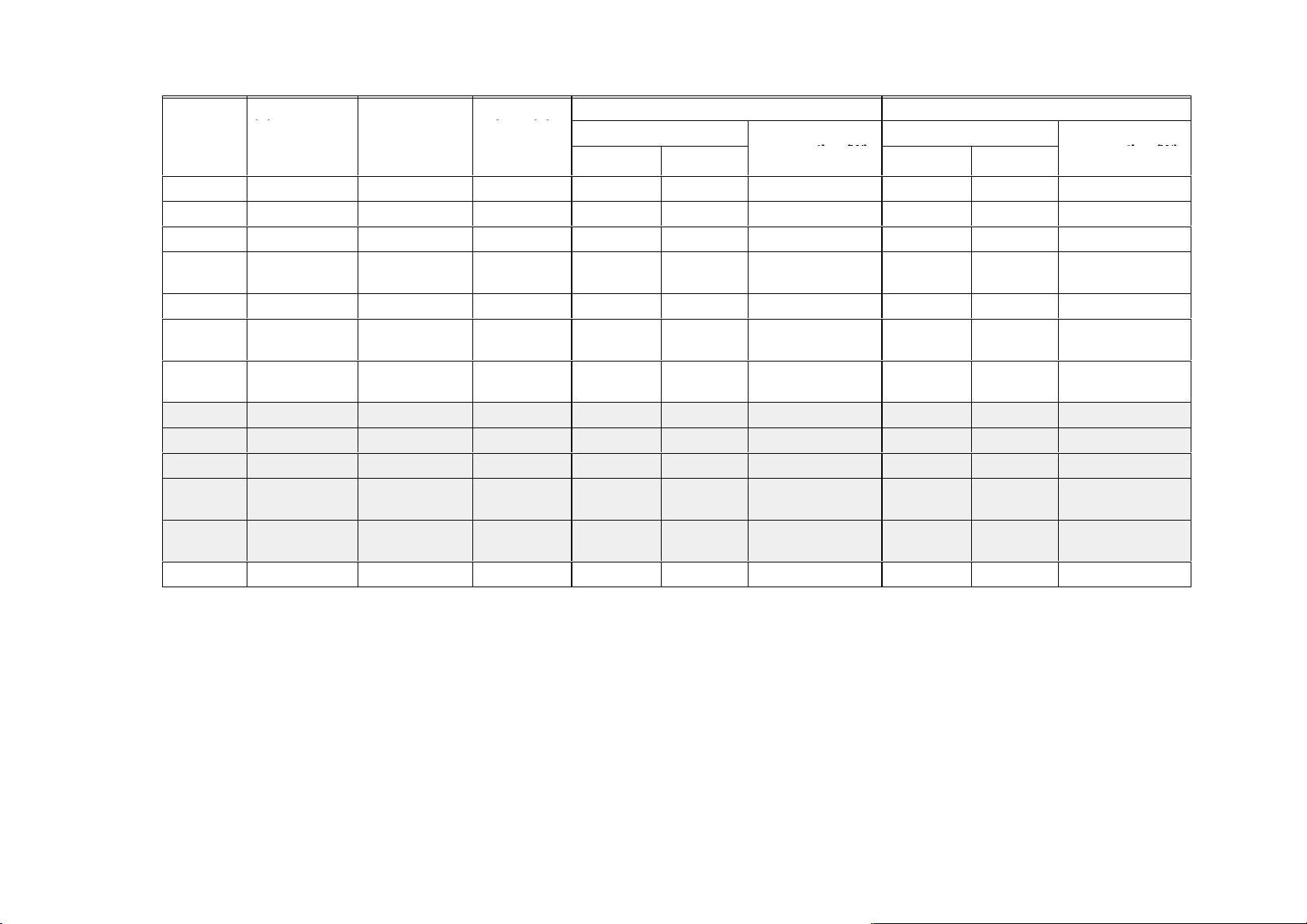
Table 2.
Model
VR860.XA 24, 50 Hz Standard 19.5 ... 27 0.28 0.4 3.5 0.211 0.242 3.8
VR862.XA 24, 50 Hz Standard 19.5 ... 27 0.28 0.4 3.5 0.211 0.242 3.8
VR860.XA 24, 50 Hz Upgraded 19.5 ... 27 0.42 0.54 4.8 0.211 0.242 3.8
VR860.XA 24, 50 Hz Upgraded, low
VR860.XA 24, 60 Hz Standard 19.5 ... 27 0.4 0.485 4.9 0.266 0.31 4.7
VR863.XA 24, 50 Hz Valve class
VR864.XA 24, 50 Hz Valve class
VR860.X 24,50 Hz Standard 19.5 ... 27 0.45 0.56 7 0.211 0.242 3.8
VR860.X 24,60 Hz Standard 19.5 ... 27 0.55 0.69 8.3 0.266 0.242 4.7
26
VR862.X 24,50 Hz Standard 19.5 ... 27 0.45 0.56 7 0.211 0.242 3.8
VR863.X 24,50 Hz Valve class
VR864.X 24,50 Hz Valve class
VR860.XB 24, 50 Hz Standard 19.5 ... 27 0.07 0.85 9.1 0.211 0.242 3.8
Voltage
(V) voltage (V)
Remark Operable
19.5 ... 27 0.42 0.54 4.8 0.121 0.139 2.1
consumption
19.5 ... 27 0.42 0.54 4.8 0.211 0.242 3.8
A+D, small coil
19.5 ... 27 0.42 0.54 4.8 0.211 0.242 3.8
A+C, small coil
19.5 ... 27 0.7 0.85 9.1 0.211 0.242 3.8
A+D, large coil
19.5 ... 27 0.7 0.85 9.1 0.211 0.242 3.8
A+C, large coil
First solenoid operator Main valve operator
Current (A) Nominal power
Nominal At 110%
consumption (W)
Current (A) Nominal power
Nominal
At 110%
ELECTRICAL DATA LOW VOLTAGE
consumption (W)
EN2R--9003 9212R2--NE
Page 27
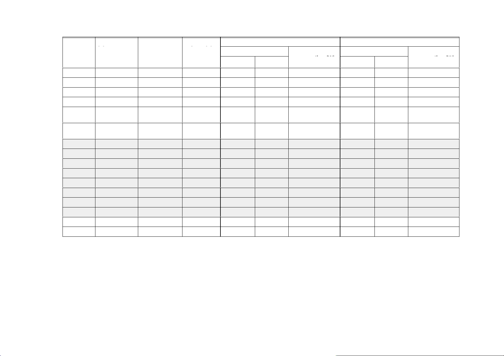
Table 3.
Model
VR460.XA 220/240, 50 Hz Standard 187 ... 264 0.032/0.036 0.048 3.6/4.7 0.021/0.024 0.028 3.4/4.5
VR462.XA 220/240, 50 Hz Standard 187 ... 264 0.032/0.036 0.048 3.6/4.7 0.021/0.024 0.028 3.4/4.5
VR460.XA 230, 50 Hz Upgraded 196 ... 253 0.042 0.052 4.8 0.021/0.024 0.028 3.4/4.5
VR460.XA 220, 60 Hz Standard 187 ... 242 0.045 0.055 4.9 0.021 0.025 3.5
VR463.XA 230, 50 Hz Valve class
VR464.XA 230, 50 Hz Valve class
VR460.X 220/240, 50 Hz Standard 187 ... 264 0.05/0.06 0.075 6.5/8 0.021/0.024 0.028 3.4/4.5
VR460.X 220,50 Hz P
VR460.X 220,60 Hz Standard 187 ... 242 0.057 0.07 8.3 0.021 0.025 3.5
VR462.X 220/240, 50 Hz 187 ... 264 0.05/0.067 0.075 6.5/8 0.021/0.024 0.028 3.4/4.5
27
VR463.X 220,50 Hz Standard 187 ... 242 0.07 0.085 9.1 0.021/0.024 0.028 3.4/4.5
VR464.X 220,50 Hz Standard 187 ... 242 0.07 0.085 9.1 0.021/0.024 0.028 3.4/4.5
VR463.X 240,50 Hz Standard 204 ... 264 0.06 0.075 8 0.021/0.024 0.028 3.4/4.5
VR464.X 240,50 Hz Standard 204 ... 264 0.06 0.075 8 0.021/0.024 0.028 3.4/4.5
VR460.XB 220, 50 Hz Standard 187 ... 242 0.07 0.085 9.1 0.021/0.024 0.028 3.4/4.5
VR460.XB 240, 50 Hz Standard 204 ... 264 0.06 0.075 8 0.021/0.024 0.028 3.4/4.5
Voltage
(V) voltage (V)
Remark Operable
196 ... 253 0.042 0.052 4.8 0.021/0.024 0.028 3.4/4.5
A+D, small coil
196 ... 253 0.042 0.052 4.8 0.021/0.024 0.028 3.4/4.5
A+C, small coil
130 mbar 187 ... 242 0.07 0.085 9.1 0.021/0.024 0.028 3.4/4.5
max.
First solenoid operator Main valve operator
Current (A) Nominal power
Nominal At 110%
consumption (W)
Current (A) Nominal power
Nominal
At 110%
ELECTRICAL DATA LINE VOLTAGE
consumption (W)
EN2R--9003 9212R2--NE
Page 28

PERFORMANCE CHARACTERISTICS
Maximum allowable leakage
Each Compact Automatichas been factory tested to meet the
followingleakage requirements:
• outerwall: 50 cm
• safety valve: 40 cm
• main valve (plus operator inlet valve): 40 cm
3
/hat test pressure of 150 mbar.
3
/hat test pressure of 8 and 150 mbar.
3
/hat test
pressure of 8 and 150 mbar.
Outlet pressure adjustment range capability
Natural/manuf. gas: 2.5 ... 20 mbar.
Natural/LP gas: 3 ... 37 mbar.
LP gas: 5 ... 50 mbar.
10 ... 60 mbar.
Pilot flow
Pilot flow capacity will not be less than 0.1 m
3
/hat 9 mbar
pressure drop.
Bleed off/recovery time of servo system
The bleed off/recovery time of the standard
SOFTLITE system
shall be within 15 seconds from operator de--energization.
For
SOFTLITE system with switchable SOFTLITE adapter the
bleed off/recovery time shall be within 30 seconds from
operatorde--energization.
High pressure test
In the ”OFF” condition, the Compact Automatic will withstand
3 bar (air)inlet pressure without damage. Attempts to operate
the Compact Automatic, while in this condition will not
damage it.
Operable voltage range
The Compact Automatic will function satisfactory between
85% and 110%of the rated voltage. See table 2. and 3.
Valve closing characteristics
The Compact Automatic will close within 1 second from
operatorde--energization at an inlet pressure of 22.5 mbar
and minimal 2.5 mbar pressure drop.
Main valve opening characteristics
Fastopeningversions
Under conditions where the supply pressure is at least 2.5
mbar above the outlet pressure setting, the dead time shall be
1 s maximum except fast opening versions with 0.2 mm inlet
orifice and upright position the dead time will be 2.5 s
maximum.
Outletpressure will reach 50% of the outlet pressure setting
within 1 second from start of flow or 75% within 2 seconds.
Full outlet pressure will be reached within 5 seconds.
Version without regulation or with throttle valve will reach full
outlet pressure within 5 seconds.
SOFTLITE versions See table 5. pag e 29
At standard test conditions the adjusted outlet pressure will be
reached between 5 and 20 seconds from start of flow (for LP
gas between 4 and 10 seconds)
Oscillation
Maximum oscillation under all circumstances:
{
0.5 mbar.
Tapsensitivityof outlet pressure set p oint
For all gases the maximum deviation may be 1 mbar.
Repeatability of outlet pressure set point
For all gases the maximum deviation from set point is:
mbar or
p
3% of the set point value, whichever is the
p
0.3
greatest.
Table 4. Totalset point shift
Pressure range
Tolerance
(mbar)
2.5 ... 20 6%of the set point value or 1 mbar
whichever is the greatest
3 ... 37 6% of the set point value or 1.5 mbar
whichever is the greatest
5 ... 50 6% of the set point value or 2.2 mbar
whichever is the greatest
5 ... 50 6% of the set point value or 2.2 mbar
whichever is the greatest
10 ... 60 6% of the set point value or 2.2 mbar
whichever is the greatest
Design life
500.000 cycles for safety and main valve operator.
Cycle frequency max.100 cycles /h.
28
EN2R--9003 9212R2--NE
Page 29

SOFTLITE
numberpressur
e
for
(mbar)1.5safter
number
Table 5. Main valve (class D only) opening characteristics SOFTLITE versions
Inlet
pressure
(mbar)
Kind of gas Applicable
for
switchable
softlite
adapter
Dead time (s) max Outlet pressure
Upright
position
Horizontal
position
(mbar) 1.5 s after
start of flow**
3
5
7
9
10
3
5
7
9
10
5
7
9
10
5
7
9
10
5
7
9
10
5
7
9
10
20 G 20/25 no 2.0***
1.5
1.5
1.5
1.5
yes 1.8** *
1.3
1.3
1.3
1.3
37 G 30/31 no 2.5
1.8
1.8
1.8
yes 2.0
1.5
1.5
1.5
50 G 30/31 no 3.3
1.5
1.5
1.5
yes 2.5
1.3
1.3
1.3
** For suffix T with throttle full open
*** In case of closed combustion chamber with negative pressure, deadtime is 1.5 s
1.7
1.2
1.2
1.2
1.2
1.5
1.0
1.0
1.0
1.0
1.8
1.5
1.5
1.5
1.4
1.2
1.2
1.2
2.4
1.2
1.2
1.2
1.8
1.0
1.0
1.0
2.0 ... 4.0
2.5 ... 6.0
4.5 ... 7.5
6.5 ... 9.0
9.0 ... 15.0
2.0 ... 3.5
3.0 ... 5.5
5.0 ... 7.0
7.0 ... 9.0
9.5 ...15.0
1.0 ... 4.5
2.5 ... 6.5
4.5 ... 8.0
7.5 ...14.5
1.5 ... 4.0
3.0 ... 6.0
5.0 ... 7.5
8.0 ... 14.0
1.0 ... 4.5
2.5 ... 6.5
3.5 ... 8.0
6.5 ...14.5
1.5 ... 4.0
2.5 ... 5.5
4.0 ... 7.5
7.5 ... 14.0
29
EN2R--9003 9212R2--NE
Page 30
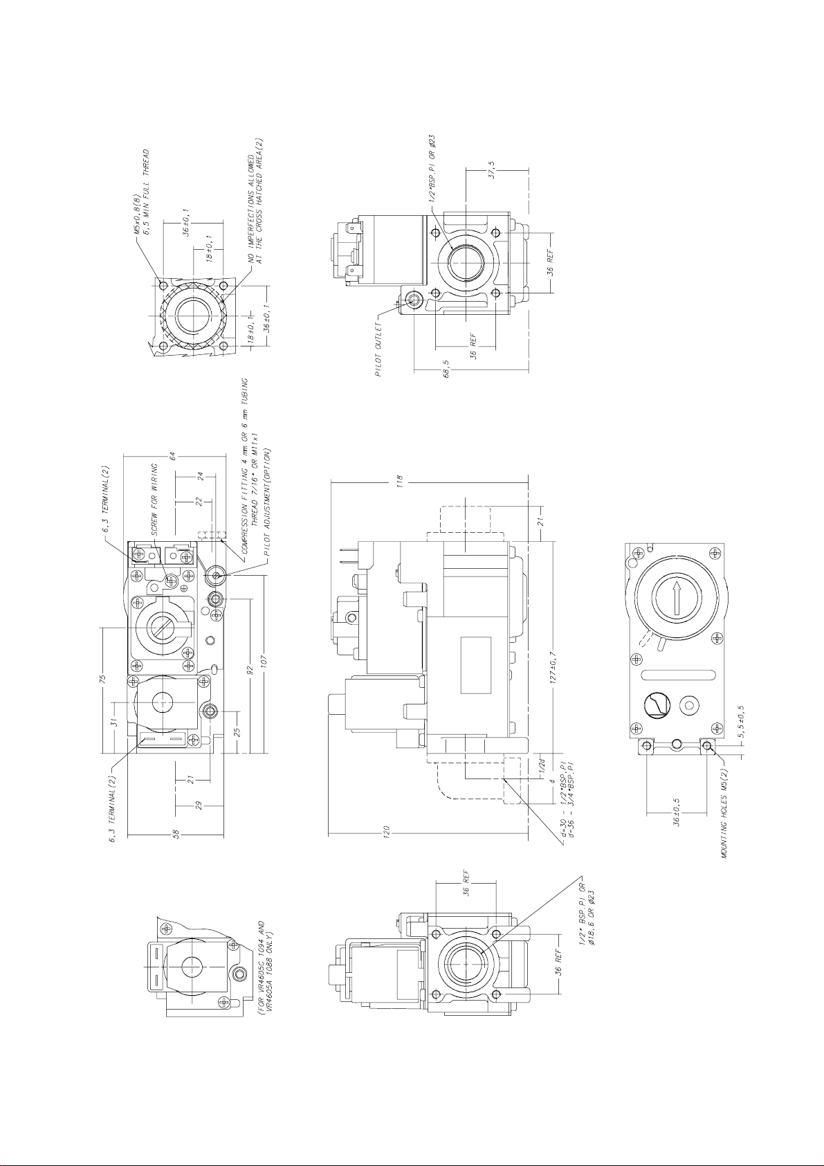
DIMENSIONAL DRAWING VR46../VR86..A/C, AB/CB
30
EN2R--9003 9212R2--NE
Page 31
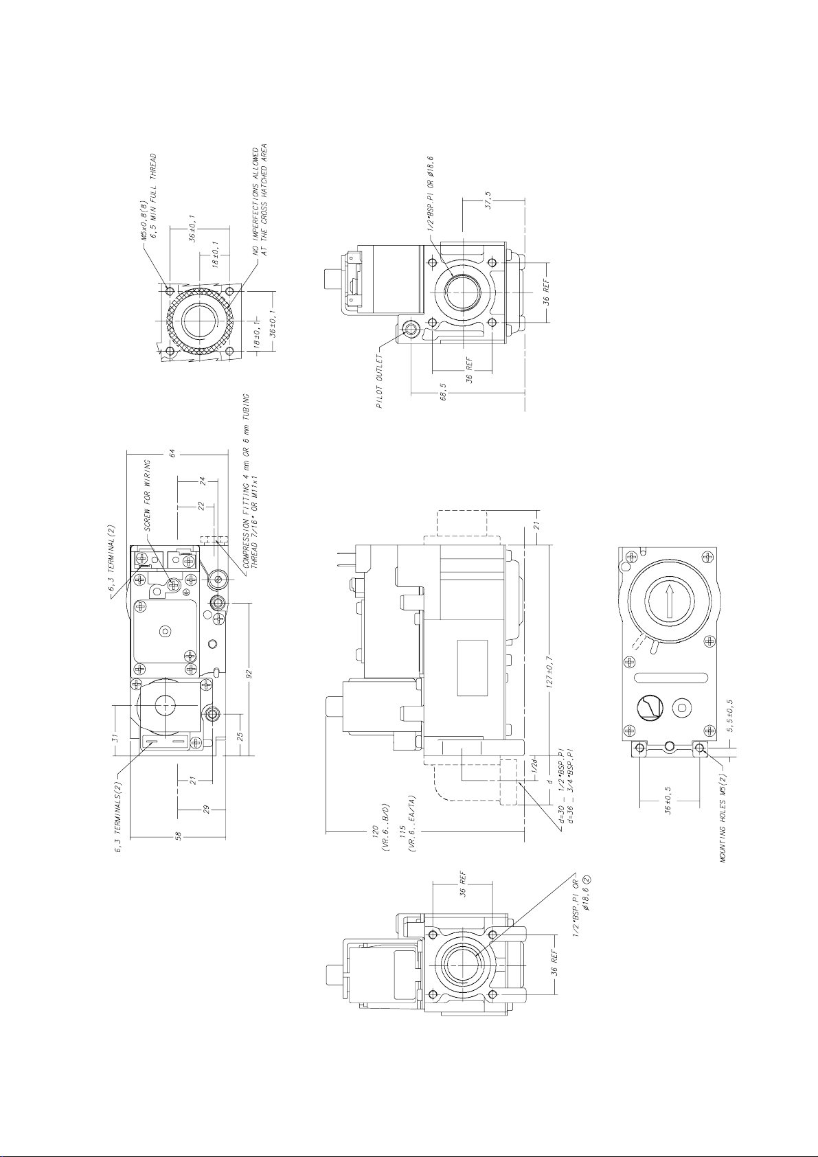
DIMENSIONAL DRAWING VR46../VR86..B/D
31
EN2R--9003 9212R2--NE
Page 32
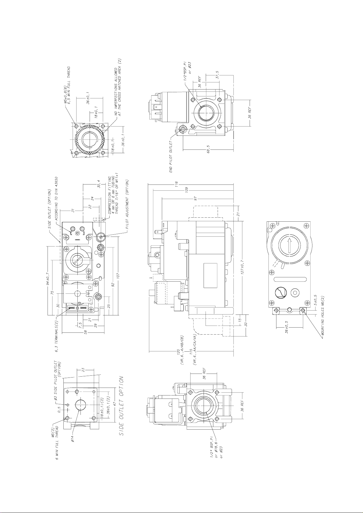
DIMENSIONAL DRAWING VR46../VR86..A/C, AA/CA, AB/CB,VA
32
EN2R--9003 9212R2--NE
Page 33
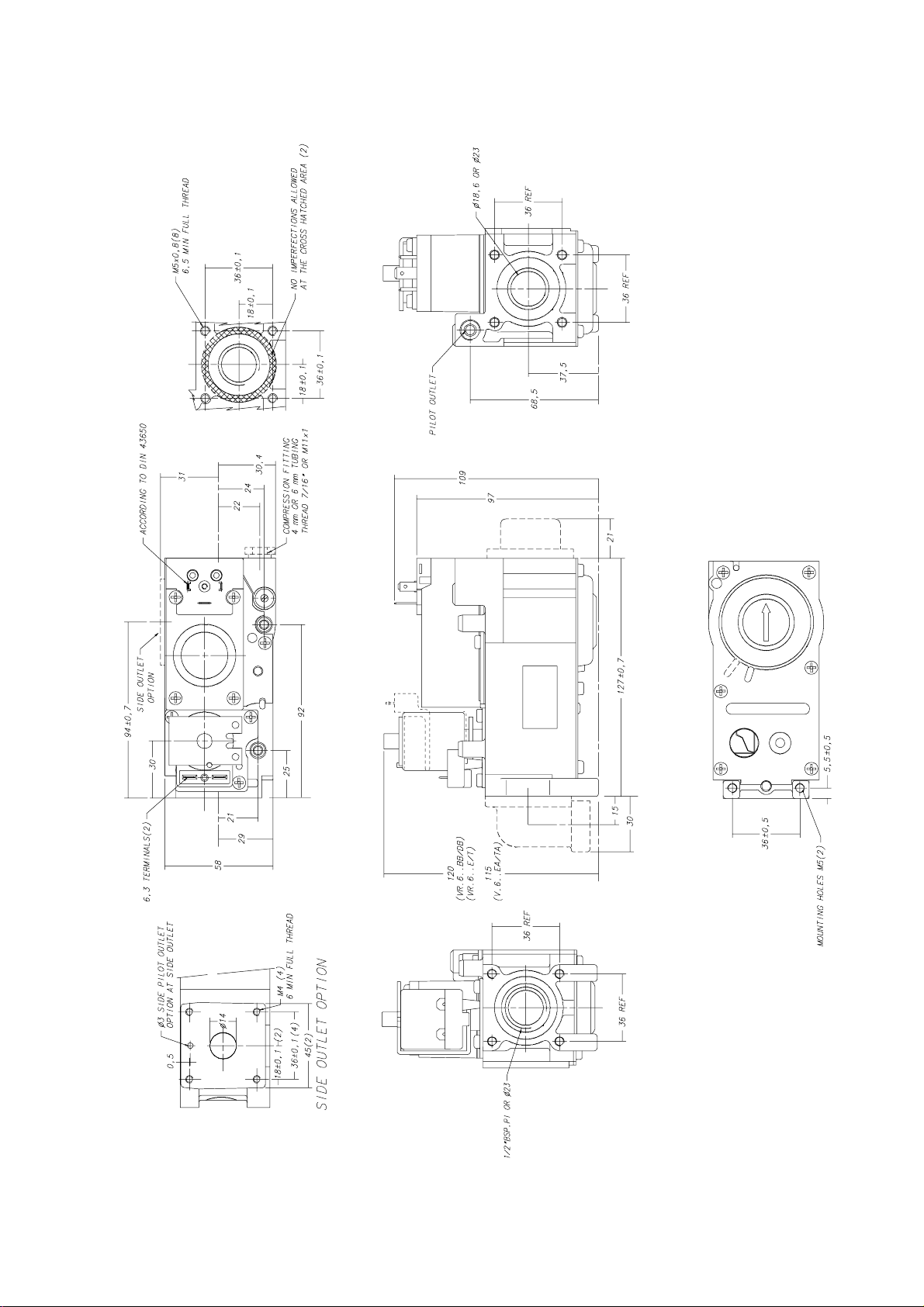
DIMENSIONAL DRAWING VR46../VR86..E/T, EA/TA
33
EN2R--9003 9212R2--NE
Page 34
INSTALLATION
WARNING
Take care that installer is a trained experienced
service man.
Turn off gas supply before starting installation.
Disconnect power supply to prevent electricalshock
and/or equipment damage.
Mountingposition
The Compact Automatic can be mounted 0 to 90 degrees in
any directionfrom the upright position (from the position
when the operators are on top).
Maingasconnection
• Take care that dirt cannot enter the Compact Automatic
during handling.
• Use a sound taper fitting with thread according to ISO 7/1
(BS 21) or a piece of new, properly reamed pipe, free from
swarf.
• Do not thread or tighten the pipe or pipe fitting too far (see
table below). Otherwise valve distortionand malfunction
could result.
Pipe size (inch)
1
/
2
• Apply a moderate amount of good quality thread
compound to the pipe or fitting only,leaving the two end
threads bare. PTFE tape may be used as an alternative.
• Ensure the gas flows in the same direction as the arrow on
the bottom of the Compact Automatic.
Pressure feedback connection
Max. length of pipe thread (mm)
18.6
WARNING
To avoid decreasing of performance of pressure
regulatorby pinching offthe pressure feedback tubing,
it is to be recommended to use a metal tubing.
Pilot gas connection (if applicable) at outlet side
• Square off the end of tubing and remove burrs.
• Slip compression fittingover tubing.
• Inserttubing into Compact Automatic housing until it
bottoms,slide fitting into place and turn finger tight.
• Use a wrench to tighten fitting about 1
finger tight to shear of the olive. Do not use jointing
compound.
• Connect other end of tubing to pilot burner according to the
manufacturer’s instructions.
1
/2turn beyond
CAUTION
Do not bend tubing at Compact Automatic after
compression fitting has been tightened, as this may
result in gas leakage at the connection.
Pilot gas connection (if applicable) at side outlet
The pilot outlet connection at the side is only applicable with a
special flange.
WARNING
Tightness test after installation
Paint all pipe connections and gaskets with a strong
soap and water solution.
Start the appliance and check for bubbles. If a leak is
found in a pipe connection, remake the joint.A gasket
leak can usually be stopped by tighteningthe
mounting screws. Otherwise,replace the gasket.
Be careful not to clog bleed vent parts with solution
residue. Remember bleed vent parts will discharge air
during gas valve opening or closing giving false
indicationof leakage.
Electricalconnection
CAUTION
Switch off power supply before making electrical
connections.
Never jumper the terminals of low voltage Compact
Automaticsince this may burn out the room
thermostatheat anticipator.
Take care that wiring is in accordance with local
regulations.
Use lead wire which can withstand 105
The electricon/off operator is provided with 6.3 mm quick
connect terminals suitable for 6.3 mm receptacles (e.g.
”Series250” AMP fasteners).
The electricon/off servo operator is provided with both 6.3
mm terminals suitable for 6.3 mm receptacles (e.g. ”Series
250” AMP fasteners) and screw terminals, or is provided with
quick connect terminals suitable for 6.3 mm receptacles (e.g.
”Series250” AMP fasteners) or for a female connector
according to DIN 43650.
Wiring
Follow the instructions supplied by the appliance
manufacturer.
E
C ambient.
34
EN2R--9003 9212R2--NE
Page 35

ADJUSTMENTS AND FINAL CHECKOUT
WARNING
Adjustmentsmust be made by qualified persons only.
If the appliance manufacturersupplies checkout and/
or service and maintenance instructionscarefully
followthem. If these instructions are not provided then
use the procedure outlined below.
CAUTION
To ensure a safe closing of the valves, it is essential
that voltage over the terminalsof both electric
operatorsis reduced to 0 Volt.
Outlet pressure adjustment servo regulated versions
(see page 30 or 32)
• Disconnect pressure feedback connection (if applicable)
• Energize both electric operators in order to have gas input
to burner.
• Check gas input to the appliance using a clocking gas
meter or alternatively a pressure gauge connected to the
outlet pressure tap.
• Remove pressure regulator cap screw to expose pressure
regulatoradjustment screw.
• Slowly turn adjustment screw with a small screw driver until
the burner pressure required is recorded on the pressure
gauge.
Turn adjustment screw clockwise to increase or
counter--clockwise to decrease gas pressure to
the burner.
• For non--regulating mode (LP gas) turn adjustment screw
clockwise until it stops.
• Replace pressure regulator cap screw.
• Connect pressure feedback connection (if applicable).
Outlet pressure adjustment throttle version s (see p age NO TAGor 33)
• Energize both electric operators in order to have gas input
to burner.
• Check input to the appliance using a clocking gas meter or
alternatively a pressure gauge connected to the outlet
pressure tap.
• Turn the flow adjustmentscrew with a screw driver
either way until the burner pressure requiredis
recorded on the pressure gauge.
Checkofslowopening(
The
SOFTLITE pressure is factory set.
Check burner performance at this pressure observing burner
ignitionand flame c haracteristics.Burner should ignite
promptlyand without flash back to orifice and all ports should
remain lit. Cycle burner several times (wait 15 seconds
between cycles to allow servo system to resume slow open
action).Repeat check of slow opening afterallowing the
appliance to cool down.
Finalcheckoutof theinstallation
Set appliance in operation after any adjustment and observe
several complete cycles to ensure that all burner components
functioncorrectly.
SOFTLITE)
35
EN2R--9003 9212R2--NE
Page 36
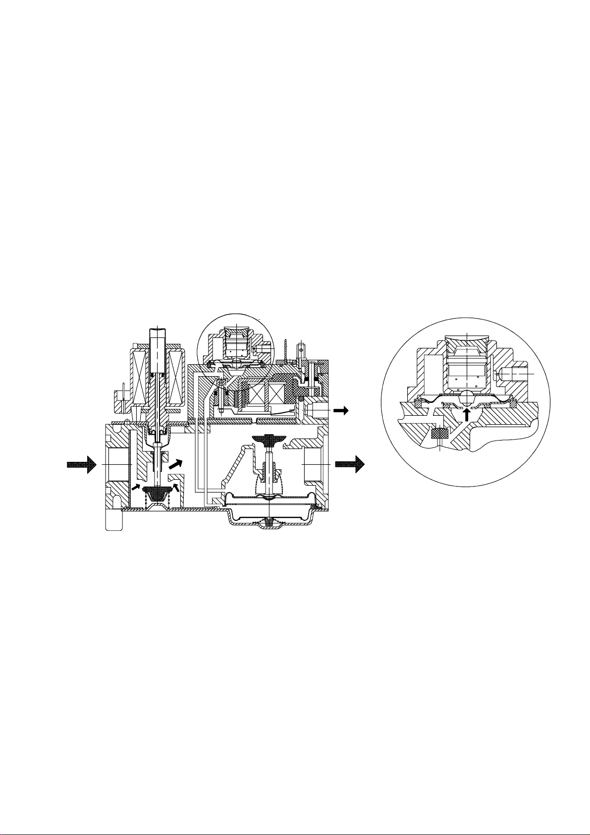
CONSTRUCTION AND WORKING PRINCIPLES
Servo pressure regulation working. See fig. 1.
The Compact Automatic features the positive servo system,
i.e. the main gas valve is closed by spring pressure in the
normal shut down position and can only be opened when gas
pressure is sufficientto overcome the spring force. This
valuable built in safety feature ensures the main valve wil
automatically close in the event of power or gas supply failure.
The heart of the system is the servo pressure regulator which
consists of a pressure relief valve integrated in a regulator
diaphragm which is fitted above and controlsthe main valve.
When the direct on/off operator and servo on/offoperator are
energized, inlet gas flows through the servo orificeand
through the open operator valve into the servo system and
into the regulator. This servo gas moves the main valve
diaphragm upwards enough to open the main valve. As soon
as the main v alve has opened, the outlet pressure generated
by the Compact Automatic will be sensed by the regulator
diaphragm via the feedback channel.
When the force operated by the pressure is greater than that
preset by the adjusment screw,the regulatorvalve opens
relieving some of the working pressure.This reduces the
force against the main valve spring allowing the main valve to
close proportionately. Thus the main valve limits the outlet (or
burner)pressure to the preset level.
As a result, outlet pressure is continuously maintainedby
comparing it to the preset pressure and adjusting the position
of the main valve accordingly. This means that a constant
outlet pressure is maintainedregardless of inlet pressure
variations.
At shut down, the small volume of working gas in the regulator
and in the diaphragm chamber is dumped into the main outlet
chamber.
A reference pressure feedback connection further regulates
the outlet pressure by compensating for differences in the air
pressure in the combustion chamber and at the valve.
If pressure regulation working is not needed, the regulator
spring can be blocked by turning the adjustment screw down
until it stops or the pressure regulation is removed. In these
cases the full servo gas pressure opens the main valve as far
as the pressure drop allows.
ON position
Fig. 1. Servo pressure regulator working
36
EN2R--9003 9212R2--NE
Page 37
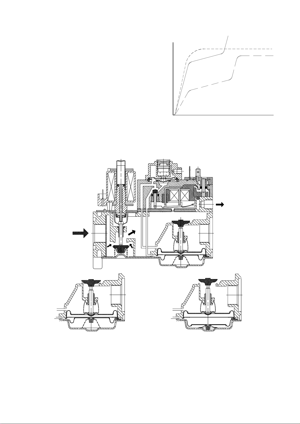
SOFTLITE working
Some burners function well using fast opening valve with the
pressure build up as shown in fig. 1. However, other
burner/appliance combinations need a means of improving
their ignition characteristicsby providing quieter ignition and
reducing flame roll--out.The
SOFTLITE mechanism achieves
this by changing the profile of the outlet pressure curve as
showninfig.2.
An extra diaphragm and spring are inserted below the main
diaphragm.When the electric servo operator valve is opened,
working gas enters the
SOFTLITE module via the inlet orifice,
and is fed into the space between the diaphragms. Working
gas pressure rapidly increases to a preset level, partially
opening the main valve (see fig. 3.).
As soon as it reaches the start level it overcomes the
SOFTLITE
spring pressure. The resultantmove of the SOFTLITE
diaphragm inhibits the increase of working gas pressure. Only
when the
SOFTLITE spring has been totally compressed does
the working gas pressure increase rapidly once again until the
full fire position is reached.
SOFTLITE with adapter
Fast open
SOFTLITE
Outletpressure (mbar0
0
Time (s)
Fig. 2. Opening characteristics
SOFTLITE ON position,
SOFTLITE gas only, main valve partially open
Fig. 3. Servo pressure regulation
OFF position
37
SOFTLITE ON position, main valve open
SOFTLITE models
EN2R--9003 9212R2--NE
Page 38
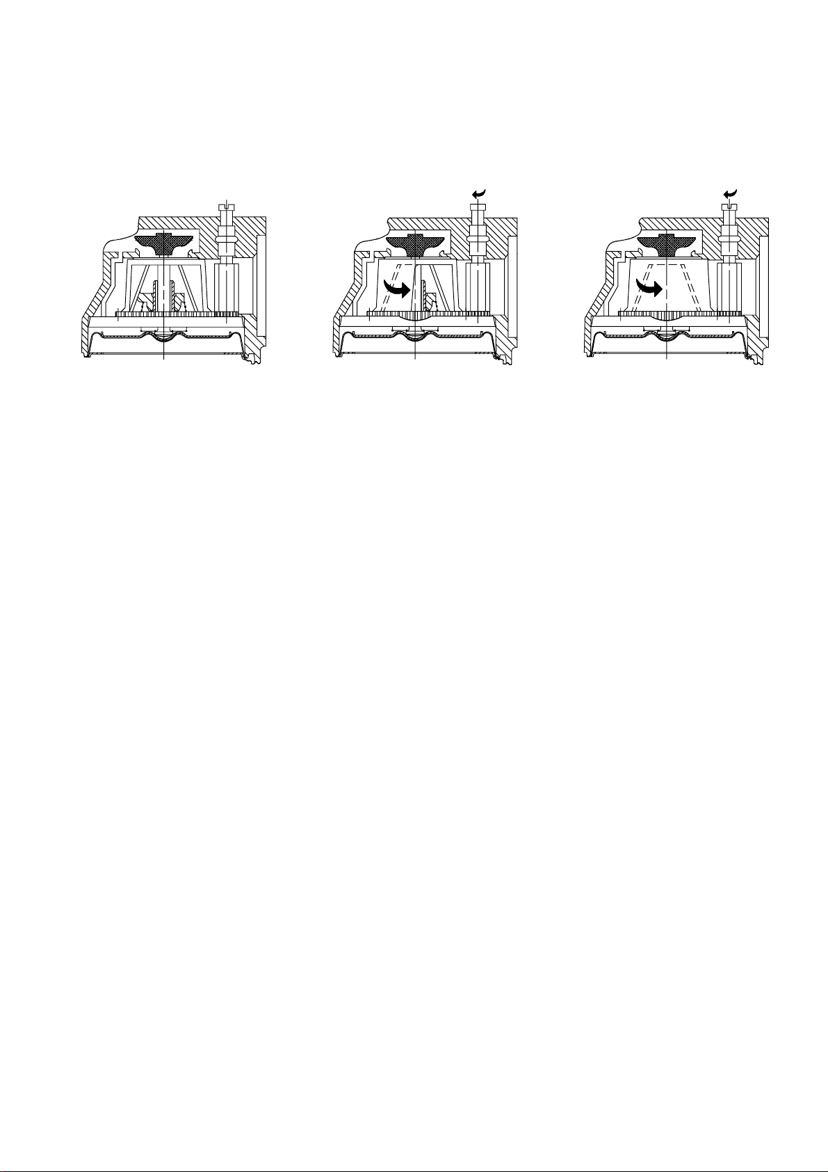
Throttle valve working (see fig. 4. )
The throttle valve is situated after the main valve and can be
adjusted by a screw. With the throttle the outlet pressure can
be adjusted in relation to the inlet pressure.
The throttle screw has a rotation reduction of 4 : 1 to the
throttle and can be fully rotated.
Fig. 4. Throttle adjustment
Trottle closedTrottle open
38
EN2R--9003 9212R2--NE
Page 39

QUALITY ASSURANCE STATEMENT
Products are manufactured under an ISO 9001 (BS 5750/1
1987, part 1, EN 29001) based and certified Quality System.
The quality system is described in the Honeywell Combustion
Controls Center Quality Assurance Programme and its related
operationalprocedures and instructions.
The quality system is approved by the British Standard
Institution (BSI) against certificate number FM 6 and is
reviewed twice a year by BSI.
The quality organisation is responsible for defining,
maintaining, improving and verificationof the quality systems
in the field of design, production process and field quality
service.
Assembly processes are guided by work instructions.
Patrolinspections form part of the assembly processes.
At the end of the assembly phase, all gas controls are
leakage and performancetested/adjusted.
Assembly inspection is performed by employees of the quality
controldepartment, using their own equipment.
All inspections (incoming and assembly) are performed by
trainedpersonel and according inspection procedures.
39
EN2R--9003 9212R2--NE
Page 40

STANDARDS ANDAPPROVALS
Standards
The Compact Automatic has been designed to meet the
European Standards:
• EN 88: Pressure governors
• EN 161: Automaticshut--off valves
• EN 126: Multifunctional controls.
The safety shut off valve meets c lass A or B requirements
depending on model number.
The servo operated main valve meets class D requirements in
case of VR4601/VR8601 and VR4605/VR8605 and meets
class C requirements in case of VR4615/VR8615.
According to bending stresses the Compact Automatic meets
the highest requirements (group 2).
The pressure governor meets class B performance.
Regarding electric safety,the Compact Automatic can be
used in appliances according to European Standard for
household electrical requirements
EN 60335 series.
The Compact Automatic also meets all Electro Magnetic
Compatability standards for non--industrial appliances.
Approvals
The Compact Automatic conforms with the following
EC -- Directives:
• Gas Appliance Directive (90/396/EEC)
• Low Voltage Directive (73/23/EEC)
• ElectroMagnetic Compatability Directive (89/336/EEC)
The fact that the Compact Automatic is certified to european
standards EN 88, EN 161 and EN 126 means that the
Compact Automatic meets more stringent requirements than
laid down in the essential requirementsstated in the directives
and thereforemeet the requirements in all EC and EFTA
countries.
Details per O.S. number can be found in the Approvals List.
In addition our controls have been certified by DIN--DVGW in
Germany. The registration number specific for each O.S.
number is mentioned on the label of the control.
40
EN2R--9003 9212R2--NE
Page 41
ORDERING INFORMATION
When ordering specify:
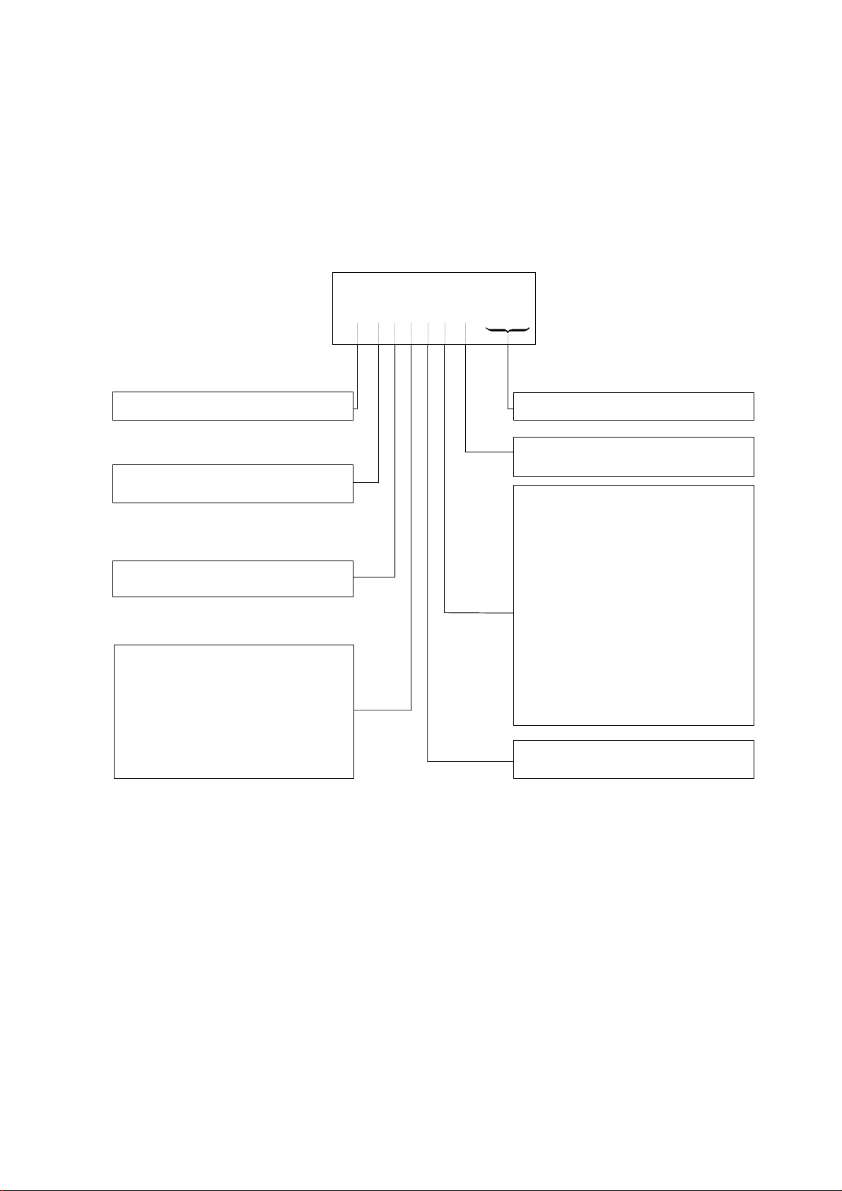
• Model number of Compact Automatic required: see fig. 5.
• Inlet and outlet pipe s izes required: note pipe sizes
determinescapacity.
• The correct pilot burner for the installation concerned: refer
to Honeywell ignition products guide EN0R--0038.
• Order numbers of replacement parts and accessories
required,i.e. flanges, compression fittings:see
replacementparts/accessories.
Ordering Spec ification number
VR
460
VR: dual valve
4: line voltage
8: low voltage
6: Compact/Compact Automatic family
Valve classification
0: Class B + D
1: Class B + C
2: Class B + B
3: Class A + D
4: Class A + C
5: Class A + B
6: Class A + A
A
(A) 9999
1
NOTE: Most models of valves, replacement parts and
accessories will be available under
”TRADELINE” label. Ask your wholesaler for
details.
Specification number
A: Low capacity model
B: High capacity model
A: fast opening with regulator
B: fast opening without regulator
C: softlite opening with regulator
D: softlite opening without regulator
E: fast opening with throttle valve
G:fast opening with combi plate
H: softlite opening with Modulec
M:fast opening with Modureg
N: softlite opening with Modureg
P: fast opening with High--Low
Q:softlite opening with High--Low
T: softlite opening with throttle valve
R: fast opening and suitable for
gas/air application
V: fast opening with integrated
1:1 gas/air regulation
1: Pilot outlet
5: No pilot outlet
Fig. 5. Model number chart
41
EN2R--9003 9212R2--NE
 Loading...