

Honeywell VC2010zz00, VC2011zz00, VC2012zz00, VC2611zz00, VC4012zz00 Quick Start Manual
...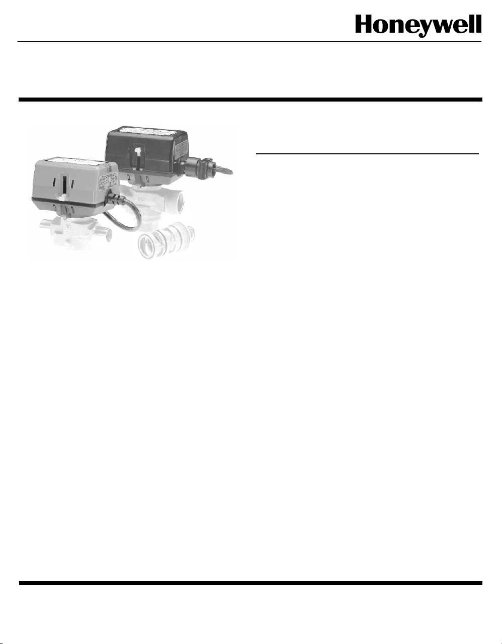
On-Off Actuator for VC Series Balanced Hydronic Valves
These 2-position (open/close) control actuators are used with VCZ
1000, 1100, 6000 and 6100 series hydronic valves in a normal
indoor environment to provide quick opening/closing to control the
flow of hot and/or chilled water or glycol solution to 60% concentration. They are designed for on-off "zone" control of heating/cooling
systems, or to control individual fan coil, baseboard radiator or
convector applications.
Depending on the model selected, the actuator can be controlled
by a low or line voltage SPST or SPDT controller, such as a room
thermostat, aquastat or flow switch.
VC80 series valve actuators are designed to be used with hardwired electronic thermostats with series anticipator or powerstealing thermostats. Recommended control thermostats include
T8601D, T8401C, T8380 and T8360 families.
VC actuators use cam-operated cartridge travel to resist water
hammer. Internal limit switches prevent motor overrun. Some of
these actuators have conformally coated printed circuit boards for
humidity resistance.
VC2, VC4, VC60, VC8
SPECIFICATIONS
The specifications following are nominal and conform to generally
accepted industry standards. Honeywell is not responsible for damages
resulting from misapplication or misuse of its products.
Voltage: Label Colour Code
24V 50Hz ; 24V 60Hz Models Blue
100-130 V 50-60 Hz Model Black
200-240 V 50-60 Hz Model Red
Power consumption:
6 Watts Max. at nominal Voltage (during valve position change).
Use 24 V Class 2 transformer.
Provide 6 VA per valve for transformer and connection wire sizing.
Maximum Duty Cycle: 15%
Nominal timing: Valve opens in 6 seconds @ 60 Hz (20% longer @
50 Hz)
Electrical termination: Available in 3 versions:
(1) Molex™ (header # 39-30-1060). Requires mating
connector (receptacle/housing # 39-01-2060). OR
(2) integral 1 meter [nominal 39"] leadwire cable.
(3) 5 feet [1.5 meter] plenum-rated cable per UL94-5V.
Includes plastic adapter for use with 3/8" flexible conduit.
End switch rating :
2.2 A inductive from 5 to 110 Vac,
1.0 A inductive above 110 to 277 Vac.
Min. DC switching capability: 5 mA @ 24 Vdc
Operating ambient temperature:
0 to 65°C [32 to 150°F]
Humidity Rating: 5-95% RH (non-condensing)
Fluid temperatures: 34 to 203°F [1 to 95°C]
Shipping & storage temperature: -40 to +65°C [-40 to +150°F]
Atmosphere: non-corrosive, non-explosive
Nominal Dimensions (Actuator only):
3-23/32" width x 2-11/16" depth x 2-3/4" height
94 mm width x 68 mm depth x 70 mm height
Accessories:
272866B Valve Flushing Cap
2003.02.24
© Honeywell Limited.
Form No. 95C-10920
MODELS:
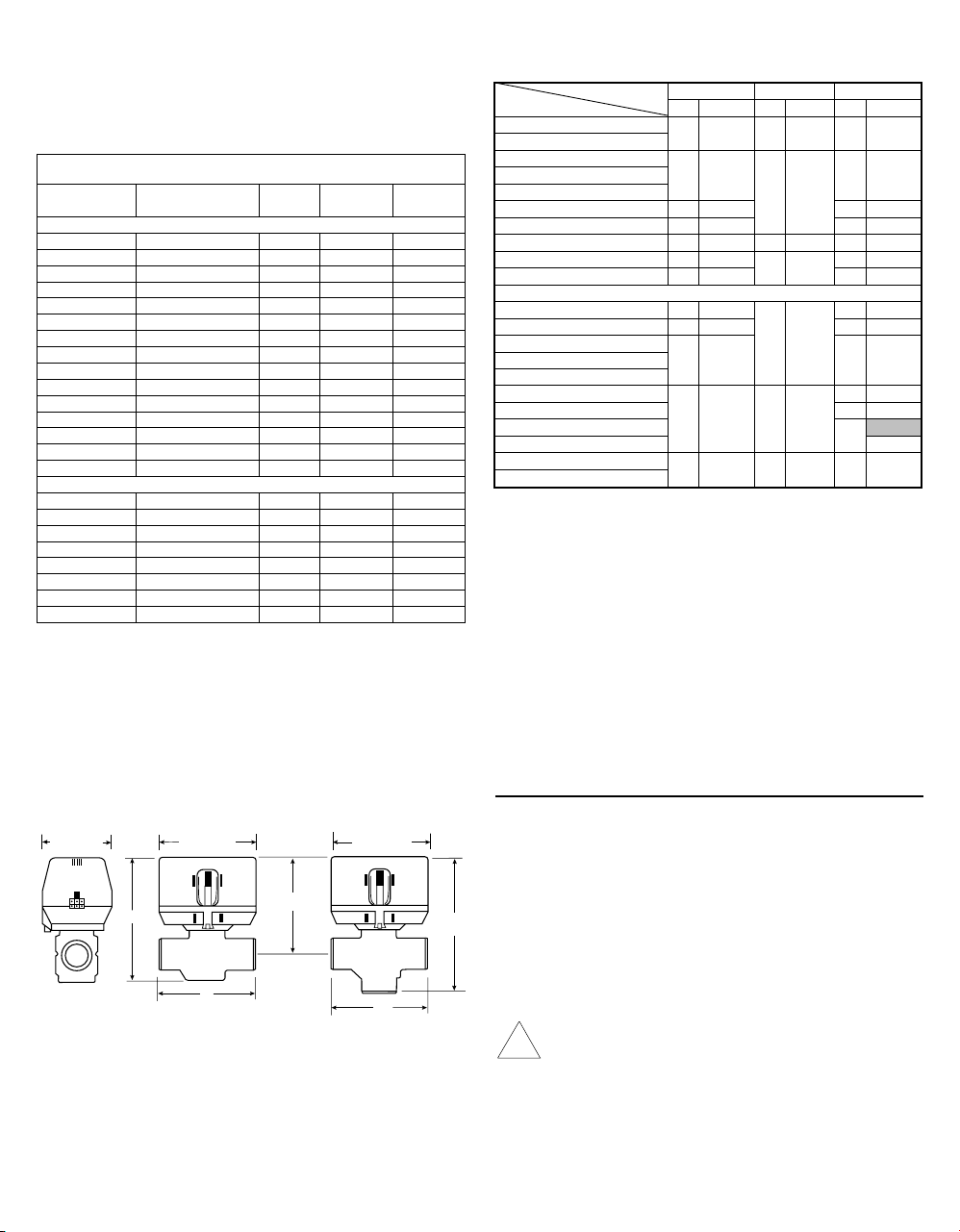
94 [3-3/4]
68 [2-3/4]
94 [3-3/4]
A
B
B
AB
A
D
90 [3-9/16]
C
C
n
Actuator Only: VC2, VC4, VC60, VC8 (See Table 1)
Bodies (Order Separately): VCZ..., (See 95C-10919)
Actuators
Model No. Power
VC2010zz00
VC2011zz00
VC2012zz00 [1]
VC2611zz00
VC4012zz00
VC4013zz00
VC4013zz11 [3]
VC4613zz00
VC6012zz00
VC6013zz00
VC6013zz11 [3]
VC6612zz00
VC6613zz00
VC8011zz00
VC8611zz00
VC2114zz11 [3]
VC2714zz11 [3]
VC4011zz11 [3]
VC4013zz11 [3]
VC8111zz11 [3]
VC8114zz11 [3]
VC8711zz11 [3]
VC8714zz11 [3]
NOTE:
[1] with Snubber circuit
[2] Plenum rated with 1.5 meter cable
[3] Model number ending with "11" has conformal coated printed circuit
board for heating/cooling use.
[4] Some models are not available in all countries. Not all VC Actuator
modes are shown.
INTERNATIONAL MODEL [4]
24V~50Hz
24V~50Hz
24V~50Hz
24V~50Hz
200-240V~50-60Hz
200-240V~50-60Hz
200-240V~50-60Hz
200-240V~50-60Hz
200-240V~50-60Hz
200-240V~50-60Hz
200-240V~50-60Hz
200-240V~50-60Hz
200-240V~50-60Hz
24V~50Hz
24V~50Hz
NORTH AMERICA MODELS [4]
24V~60Hz
24V~60Hz
120V~60Hz
200-240V~50-60Hz
24V~60Hz
24V~60Hz
24V~60Hz
24V~60Hz
Control
Table 1 - Actuator Model Identifiers
VC Valve Assembled dimensions for reference (Figure 1 & Table 2):
Figure 1 - Nominal dimensions in inches and millimetres
Auxiliary
Input
SPDT - - Molex
SPDT - - Cable
SPDT - - Molex
SPDT Yes Cable
SPST - - Molex
SPST - - Cable
SPST - - Cable
SPST Yes Cable
SPDT - - Molex
SPDT - - Cable
SPDT - - Cable
SPDT Yes Molex
SPDT Yes Cable
SPST - - Cable
SPST Yes Cable
SPDT - - Plenum[2]
SPDT Yes Plenum[2]
SPST - - Cable
SPST - - Cable
SPST - - Cable
SPST - - Plenum[2]
SPST Yes Cable
SPST Yes Plenum[2]
Switch
Special
Features
[4] Dimensio
Pipe Fitting Sizes
1/2" BSPP (int.) [2]
1/2" BSPT (int.)
C D E
mm Inches mm Inches mm Inches
98 3-7/8 111 4-3/8 136 5-11/32
3/4" BSPP (int.)
3/4" BSPT (int.)
3/4" BSPP (ext.)
22mm Compression [3] 112
1" BSPP (int.) 94
1" BSPP (ext.)
1" BSPT (int.) 94
28mm Compression [3] 116
NORTH AMERICA STANDARD MODELS
3/8" FLARE [1] 98
1/2" SWEAT 89
1/2" FLARE [1]
1/2" INVERTED FLARE [1]
94 3-11/16
113 4-7/16
4-7/16
3-11/16
95 3-11/17 114 4-7/17 137 5-11/33
3-11/16
113 4-7/16
4-9/16
3-7/8
3-1/2 130 5-1/8
111 4-3/8
98 3-7/8 136 5-11/32
1/2" NPT (int.)
3/4" NPT (int.)
3/4" SWEAT 132
1" NPT (int.)
94 3-11/16 113 4-7/16
1" SWEAT
1-1/4" SWEAT
1-1/4" NPT (int.)
110 4-5/16 118 4-5/8 142 5-5/8
[1] No adapters
[2] Suitable for use as15 mm compression fitting
[3] Dimensions shown with nuts and olives installed
[4] Some models not available in all countries
Table 2 - VC Valve assembled dimensions
MANUAL OPENER
The manual opener can be manipulated only when in the up position.
The motorized valve can be opened by firmly pushing the red manual
lever down to midway and in. This holds the valve in the open
position. This "manual open" position may be used for filling, venting,
draining the system or for opening the valve in case of power failure.
The valve can be restored manually to the closed position by
depressing the red manual lever lightly and then pulling the lever out.
The valve and actuator will return to the automatic position when
power is restored.
NOTE: If the valve is powered open (the lever is down), it can not be
manually closed unless actuator is removed.
INSTALLATION
WHEN INSTALLING THIS PRODUCT:
1. Read these instructions carefully. Failure to follow them could
damage the product or cause a hazardous condition.
2. Check the ratings given in the instructions and on the product to
make sure the product is suitable for your application.
3. Installer must be a trained, experienced service technician.
4. Always conduct a thorough checkout when installation is com-
E
pleted.
5. While not necessary to remove the actuator from the body, it can
be removed for ease of installation. The actuator can be installed
in any position to suit the most convenient wiring mode.
6. An extra 1" (25 mm) head clearance is required to remove the
actuator.
CAUTION:
!
Disconnect power supply before connecting wiring to prevent
electrical shock and equipment damage.
On 24 V systems, never jumper the valve coil terminals, even
temporarily. This may damage the thermostat.
2
130 5-1/8
140 5-1/2
136 5-11/32
136 5-11/32
147 5-13/16
136 5-11/32
130
5-1/8
5-3/16
136
5-11/32
 Loading...