

Page 1
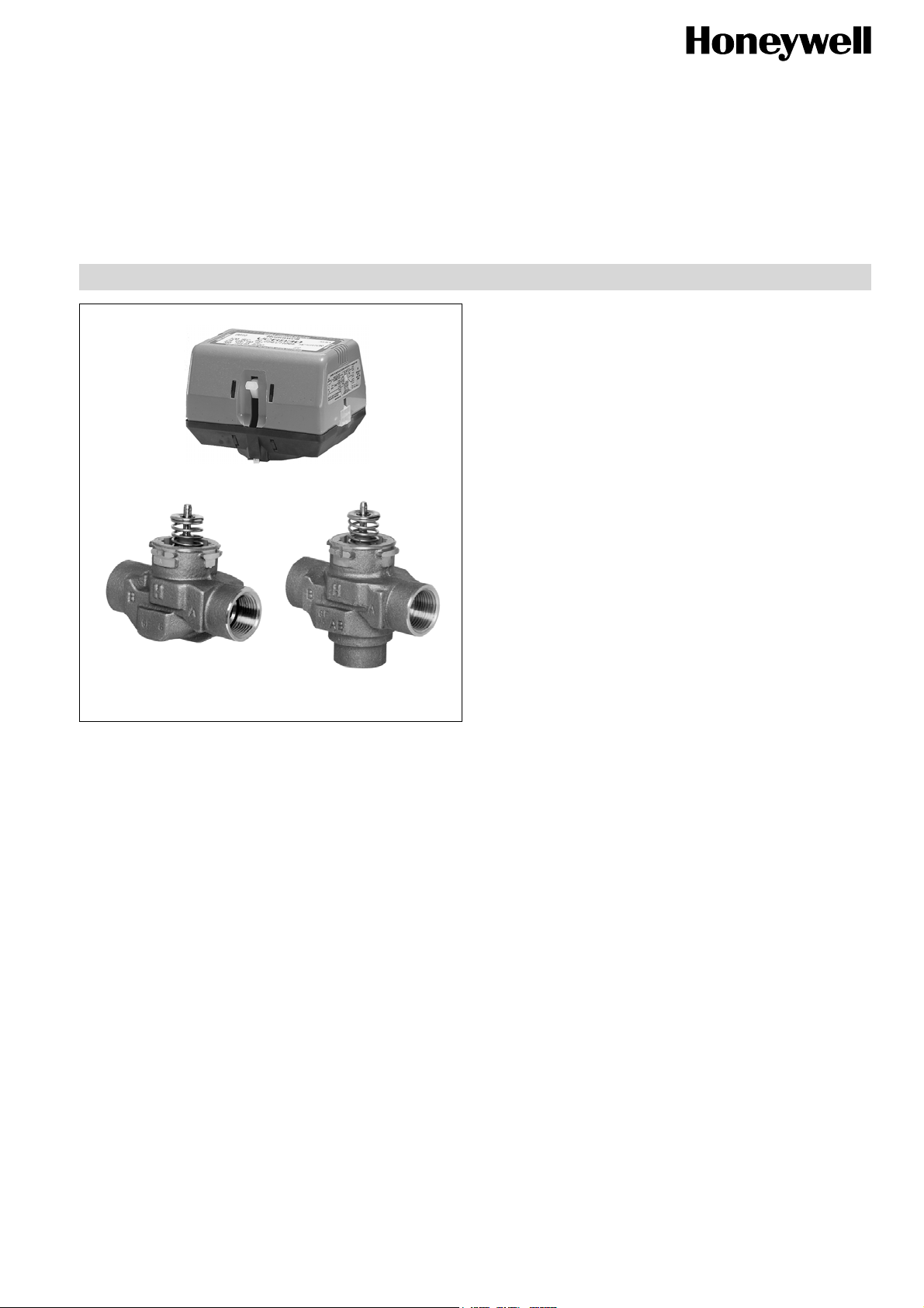
BALANCED 2-WAY AND 3-WAY HYDRONIC VALVES
VC actuator
2-way
VC valve body
Design
VC Series zone valves consist of:
• 2-way or 3-way valve housing available with various
connection ends
• Spindle and cartridge assembly
• Actuator with cable or Molex™ socket
• Pipe fittings (most versions)
Materials
• Valve housing made of bronze
• Spindle made of stainless steel
• Cartridge made of Ryton™ (polyphenylene sulphide) and
Noryl™ (polyphenylene oxide)
• O-ring seals made of EPDM rubber
• Actuator cover made of Noryl™ (94V-0)
• Actuator base made of Ryton™ (94V-0)
3-way
VC valve body
VC Series
Zone Valves
PRODUCT DATA
Application
Honeywell VC Series balanced 2-position hydronic valves are
used in domestic and small commercial heating and cooling
applications to control the flow of hot and/or cold water. They
consist of an actuator, valve and a cartridge assembly
2-way valves are designed for on-off zone control of domestic
systems. 3-way valves can be piped for either diverting or
mixing valve applications in domestic central heating and/or
cooling systems. Both versions can be used to control individual fan coil, radiator, space heater or convector applications. Depending on the model selected they can be controlled by a low or line voltage SPST or SPDT controller such
as a room thermostat, aquastat or flow switch.
VC Series hydronic valves are designed to take advantage of
sinusoidal valve actuator travel, and therefore operate silently
and reduce water hammer. Through internal logic the actuator only takes power while driving the valve to the commanded position.
The actuator head is removable without affecting the integrity
of the water system. All actuator versions are interchangeable
with any valve body, offering the highest flexibility for boiler
production line assembly, and maintenance. The valve piston
construction allows for port sealing that is independent of the
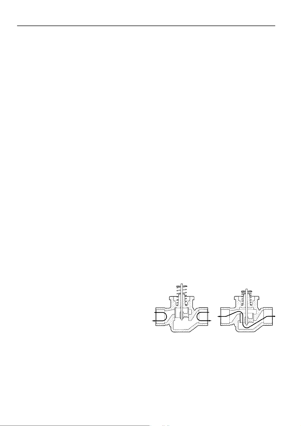
differential pressure across the valve. Flow through the 2-way
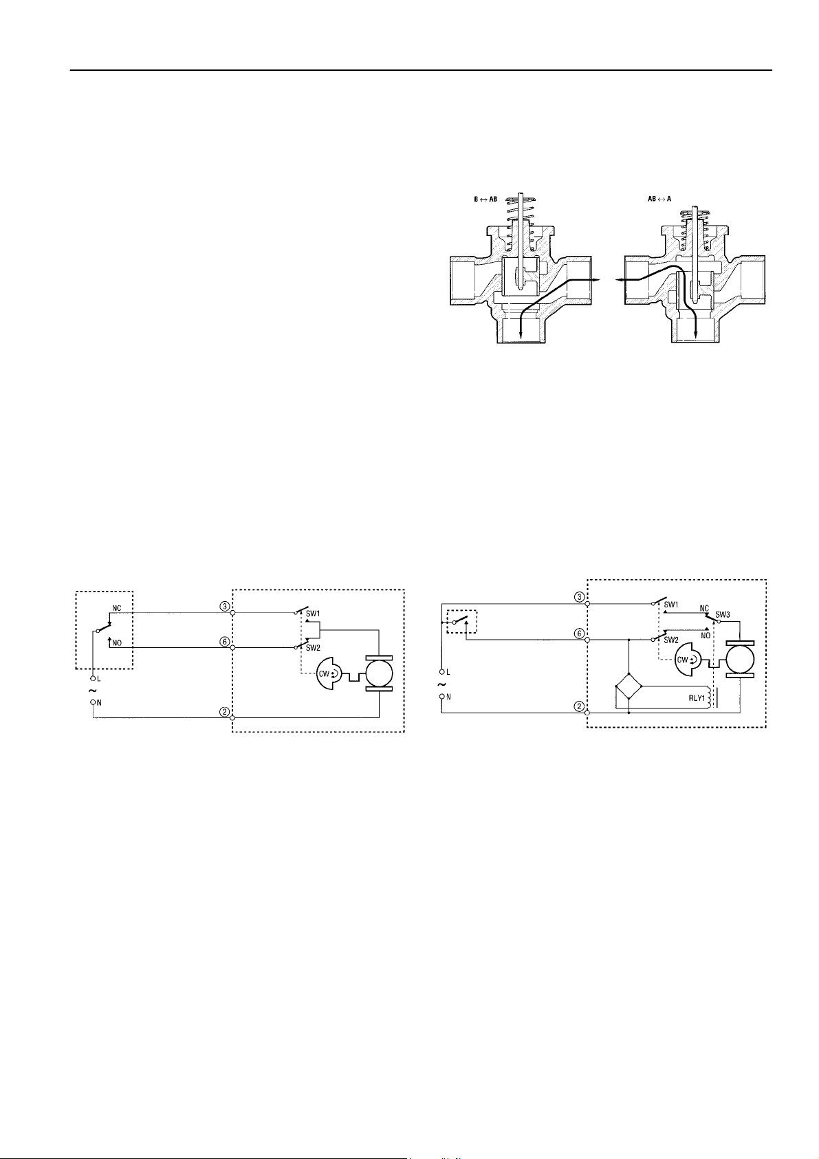
valve can be in either direction, so the ports are not designated. 3-way valves are suitable for both diverting water from
AB to A or B, and from A or B to AB.
Features
• Rugged design
• Control by a low or line voltage SPST or SPDT
controller
• Minimal actuator power consumption
• Pressure differential up to 4 bar
• Double insulated actuator
• Quick connect electrical connections
• Quick and easy replacement of moving parts
• Actuator head installation does not require draining of
the system
• High flow rate capacity
Honeywell • All rights reserved EN0H-0327GE25 R0206
Page 2
VC SERIES
Specifications
Medium Water or water-glycol mixture
pH-value 8...9.5
Operating temperature 1...95°C (34...203°F)
Ambient temperature max. 65°C (149°F)
Operating pressure max. 20 bar (290 psi) static
Differential pressure max. 4 bar (58 psi)
k
vs (cv)-values see chapter “Dimensions” below
Flow 2-way: flow can be in either
(max. 50% glycol content),
quality to VDI 2035
120°C (248°F) short duration
peak
max. 100 bar (1,450 psi) burst
direction. When actuator is not
mounted valve is in closed
position
3-way: bottom port is marked
AB. End ports are marked A and
B. When actuator is not
mounted port A is closed.
Function
VC Series 2-position hydronic valves are used in domestic
and small commercial applications to control the flow of hot
and/or cold water. They consist of an actuator, valve and a
cartridge assembly.All moving and sealing parts of the valve
are constructed in the cartridge assembly. The ports are
sealed with O-rings on the outer surface of the piston.
When the valve stem is driven down to open port A the water
will flow through the hollow piston to the other port. In case of
2-way valve
With an SPDT (3-wire) actuator
On a call for heat, the NO controller contacts close and the
valve opens. When the valve is fully open, the cam closes
switch SW1 and opens switch SW2. When the need for heat
is satisfied the NC controller contacts close, energising the
valve through SW1 and closing the valve. When the valve is
fully closed, the cam closes SW2 and opens SW1. The valve
is ready for the next call for heat.
With an SPST (2-wire and common) actuator
On a call for heat, the controller contacts close, RLY1 is energized making the NO contacts in switch SW3 causing the
valve to open. When the valve reaches the fully open position
the cam closes switch SW1 and opens switch SW2. When
the need for heat is satisfied, the controller contacts open,
RLY1 is de-energized and the valve motor is driven through
SW1 and the NC contacts of SW3. When the valve reaches
the fully closed position, the cam closes SW2 and opens
SW1. The valve is ready for the next call for heat.
Voltage 24 V, 50-60 Hz (blue label)
200-240 V, 50-60 Hz (red label)
Power consumption 4 VA
(when valve position changes)
Auxiliary switch rating 1.0 A @ 250 V, 50-60 Hz
(minimum 0.05 A @ 24 Vdc)
Nominal timing Valve opens in 7 seconds
(20% faster for 60 Hz)
Electrical termination 1. Molex™ socket: requires
mating connector,
alternatively
2. With integral 1 m leadwire
Shipping temperature -40…65°C (-40…149°F)
Humidity rating 5…95% RH (non-condensing)
Atmosphere non-corrosive, non-explosive
a 3-way valve with the piston driven down port B is sealed,
allowing flow between port AB and port A. With the stem up
the flow is between port AB and port B.
The valve family offers a variety of versions of pipe connections to suit the different applications. The valve pressure loss
characteristic is dependent on the pipe connections/ dimensions. For the actual valve rating please refer to the specification section.
For both types of actuator a power failure will leave the valve
at the position it was when interrupted. When power is restored, the valve will respond to controller demand.
Fig. 1. Fluid flow through 2-way VC valve
EN0H-0327GE25 R0206 2 Honeywell • All rights reserved
Page 3
3-way diverter valve
With an SPDT (3-wire) actuator
On a call for heat, the NO controller contacts close, the valve
closes port B and opens port A. When port A is in the fully
open position the cam closes limit switch SW1 and opens
limit switch SW2. When the need for heat is satisfied the NC
controller contacts close, energising the valve through SW1,
causing port A to close. When port A is fully closed the cam
closes SW2 and opens SW1. The valve is ready for the next
call for heat.
With an SPST (2-wire and common) actuator
On a call for heat the controller contacts close, RLY1 is energized making the NO contacts in switch SW3, causing port B
to close and port A to open. When port A reaches the fully
open position the cam closes switch SW1 and opens switch
SW2. When the need for heat is satisfied, the controller contacts open. RLY1 is de-energized making the NC contacts in
SW3 and port A is driven closed through SW1 and the NC
contacts of SW3. When port A is in the fully closed position
the cam closes SW2 and opens SW1. The valve is ready for
the next call for heat.
Wiring
Figures 3 and 4 show wiring connections for 2-way and 3-way
valves. Port A open and closed denotes valve open and closed for 2-way, and AB-A open and AB-B open for 3-way
valves respectively. A means for disconnection from the
supply having a contact separation of at least 3 mm in all
VC SERIES
For both types of actuator a power failure will leave the valve
at the position it was in when interrupted. When power is
restored, the valve will respond to controller demand.
Fig. 2. Fluid flow through 3-way VC valve
poles must be incorporated in the fixed wiring. On Molex™
connector models, actuator and auxiliary switch voltages
must be the same to meet the approval requirement. For
mixed voltages, the cable assembly version is recommended.
Fig. 3. Logic sequence diagram with 3-wire actuator for
SPDT contoller
Honeywell • All rights reserved EN0H-0327GE25 R0206
Fig. 4. Logic sequence diagram with 2-wire + common
actuator for SPST contoller
Page 4

VC SERIES
Dimensions
Fig. 5. 2-way VC valve
Table 1. Dimensions and k
Body 2-way VC valve 3-way VC valve
C kvs-value C D kvs-value
15mm compression 98 3.4 98 136 4.3
22mm compression* 112 6.8 112 140 8.6
28mm compression* 112 7.7 112 140 8.6
1/2” BSPP (external) 98 3.4 98 136 4.3
3/4” BSPP 94 6.8 94 130 7.7
1” BSPP 94 7.7 94 136 8.6
1/2” sweat 98 3.4 98 136 4.3
3/4” sweat 94 6.8 94 132 8.6
1” sweat 94 8.6 94 136 8.6
NOTE: All dimensions in mm
* Includes compression nuts and olives
vs-value
Fig. 6. 3-way VC valve
Ordering Information
Use the Valve Selection Chart to find the right version. The Valve Selection Chart provides the necessary information to put
together the OS-No. (OS=Ordering System). Example with OS-No. VC6012MP6000E:
VC6012MP6000E
Product family. Always “VC”
Actuator specifier –
see Valve Selection Chart column A
Body specifier –
see Valve Selection Chart column B
Accessories and packing specifier –
see Valve Selection Chart column E
Customisation specifier –
see Valve Selection Chart column D
Cartridge specifier –
see Valve Selection Chart column C
EN0H-0327GE25 R0206 4 Honeywell • All rights reserved
Page 5

Valve Selection Chart
VC SERIES
Honeywell • All rights reserved EN0H-0327GE25 R0206
Page 6

VC SERIES
Installation
WARNING
Installer must be a trained, experienced service
person.
When installing this product:
• Read these instructions carefully. Failure to follow
them could damage the product or cause a hazardous
condition.
• Check the ratings given in the instructions and on the
product to make sure it is suitable for your
application.
• Always conduct a thorough checkout after installation.
Plumbing
Fig. 7. Plumbing
To install a replacement actuator head
Fig. 8. Latch mechanism
CAUTION
• Disconnect power supply before wire connection to
prevent electrical shock and equipment damage.
• It is advisable to remove the actuator head from the
valve body for ease of installation. Fit the actuator
head in the most convenient position for wiring.
• On sweat fitted valves, the cartridge is shipped loose
or is removed to avoid being damaged during the solder operation.
• On 24 V systems, never short circuit the valve coil
terminals. This may burn out the heat anticipator in
the thermostat.
• To remove the actuator head 25 mm clearance is
needed above the actuator.
The valve may be plumbed in any angle but preferably not
with the actuator head below the horizontal level of the valve
body. Make sure there is enough room around the actuator
head for servicing or replacement.
When used to form part of a central heating system, do not
locate it where it will block the system vent, cold feed or any
bypass when the valve is closed.
Mount the valve directly in the tube or pipe. Do not grip
actuator head while making and tightening plumbing
connections. Either hold valve body in your hand or attach
adjustable spanner across the hexagonal or flat faces on the
valve body.
Compression models
For compression fitted models, tighten the compression nuts
enough to make a watertight seal. Take care not to
overtighten.
Important
Installation of a new actuator head does not require draining
the system providing the valve body and cartridge assembly
remain in the pipeline.
1. Disconnect power supply before servicing to avoid electrical shock or equipment damage.
2. Disconnect leadwires to actuator head, or depress tab on
Molex™
wires for rewiring.
3. The actuator head is automatically latched to valve (see
figure 8). To remove, lift up on the latch mechanism located directly below the red manual open lever. Press the
actuator head down towards the body with moderate hand
force and turn counter-clockwise by 1/8 turn (45 degrees)
simultaneously. Lift the actuator head off the valve body.
NOTE: Actuator can also be installed at right angles to valve
body but in this position latch mechanism is not engaged.
4. Install the new actuator head by reversing process in (3).
5. Reconnect leadwires or Molex™
6. Restore power.
connector and remove. Where appropriate, label
connector.
EN0H-0327GE25 R0206 6 Honeywell • All rights reserved
Page 7

VC SERIES
Adjustment and Testing
Manual Opener
The manual opener can be manipulated when in the up
position. The motorized valve can be opened by firmly
pushing the red manual lever down to midway and in (only
possible if the actuator is in the upper position). This holds all
ports in the open position, and with auxiliary switch models
the NO switch is closed. Ports A and B of 3-way valves are
opened. This 'manual open' position may be used for filling,
venting or draining the system, or for opening the valve in
case of power failure. The valve can be restored manually to
the closed position by depressing the red manual lever lightly
and then pulling it out. The valve actuator returns to the
automatic position when power is restored.
Checkout
1. Raise the set point of the thermostat above room temperature to initiate a call for heat. Valve position indicator
should move downward to the open position.
2. For all auxiliary switch models, monitor the control devices. 2-way valve: check that the valve opens, the auxiliary switch (if present) closes, and at the end of the opening stroke the circuit to the circulator or another valve is
made. 3-way valve: check that port A opens, port B
closes, the auxiliary switch (if present) operates, and at
the end of the opening stroke the circuit to the circulator or
another valve is made.
3. Lower the set point of the thermostat below room temperature.
4. Observe the control devices.
2-way valve: check that the valve closes and all auxiliary
equipment stops.
3-way valve: check that port A closes and all auxiliary
equipment stops.
Service
WARNING
This valve should be serviced by a trained,
experienced service person.
1. If the valve is leaking, drain system or isolate valve from
the system.
2. Check to see if the cartridge needs to be replaced.
3. If the gear train or the motor is damaged, replace the
actuator assembly.
NOTE: Honeywell hydronic valves are designed and tested
for silent operation in properly designed and installed systems. However, water noises may occur
as a result of excessive water velocity. Piping noises
may occur in high temperature (over 100
with insufficient water pressure.
°
C) systems
Honeywell • All rights reserved EN0H-0327GE25 R0206
Page 8

VC SERIES
Flow Diagrams
Fig. 9. Valve pressure loss characteristic
Port flow (%)
Travel (%)
Fig. 10. Typical 3-way valve diverting characteristic at constant pressure on port AB
ACS Control Products
Honeywell GmbH
Möhnestraße 55
59755 Arnsberg, Germany
Phone: +49 (2932) 9880
Fax: +49 (2932) 988324
www.honeywell.com
EN0H-0327GE25 R0206
February 2006
© 2005 Honeywell International Inc.
Subject to change • All rights reserved
Manufactured for and on behalf of the Environmental and Combustion
Controls Division of Honeywell Technologies Sàrl, Ecublens,
Route du Bois 37, Switzerland or by its Authorized Representative.
 Loading...