

Page 1
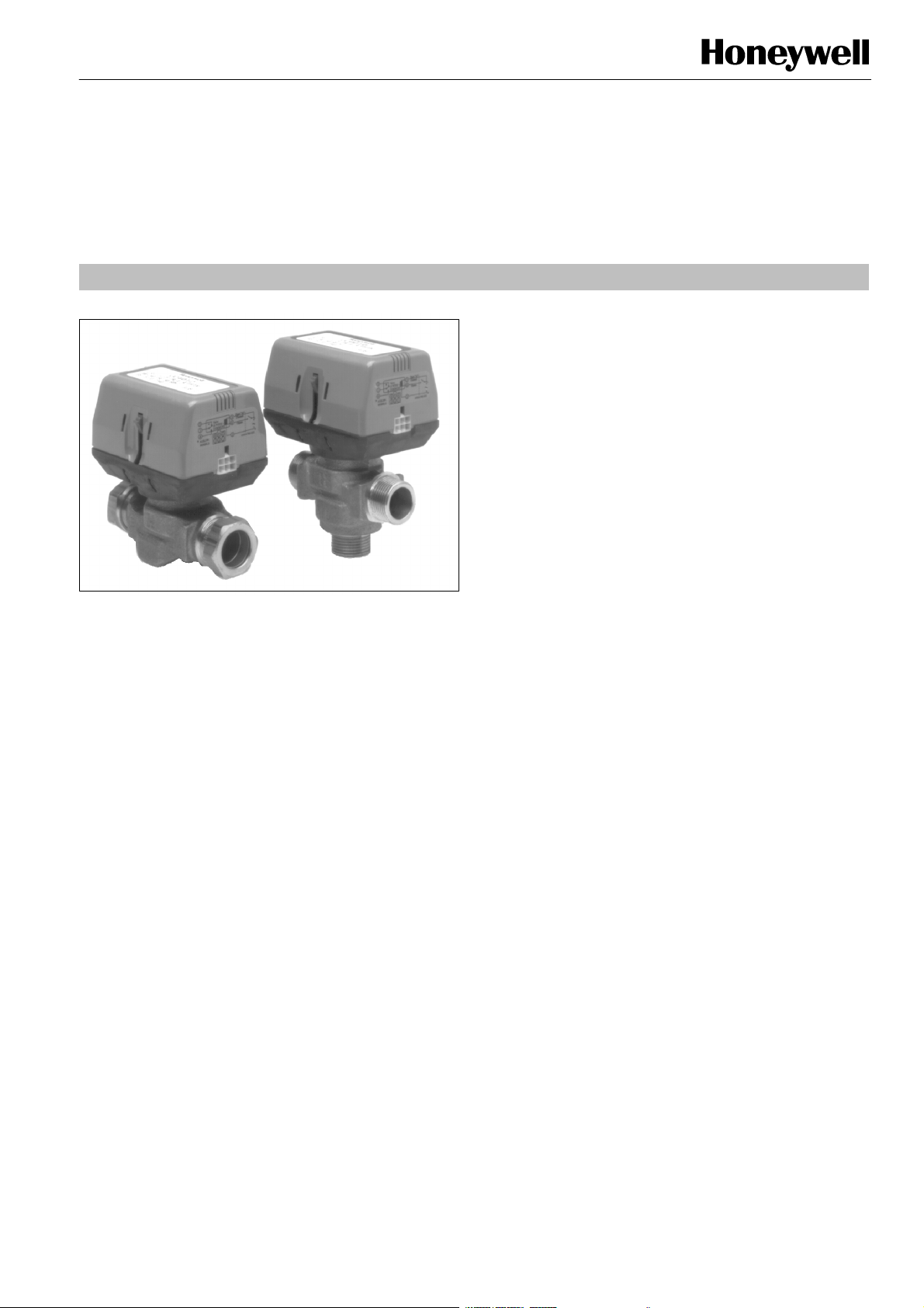
VC series
BALANCED HYDRONIC VALVES 2--WAY AND 3--WAY
PRODUCT HANDBOOK
APPLICATION
The VC series balanced hydronic valves allow greater control
of hot and/or cold water flow.
The VC series balanced hydronic valves are designed for
both domestic boiler heating and domestic cooling
applications.
Subject to change without notice. Printed in the Netherlands.
Contents
General page
Description 2
Series overview 3
Technical
Construction and operation 4
Specifications 6
Dimensions 8
Valve selection chart 9
Installation and operation
Installation data 10
Adjustment and service data 12
Various
Quality assurance statement 13
Approvals and standards 14
Ordering information 15
Standard product examples 16
Fitting for 1/2” and 15 mm valves
Fitting for 3/4” and 22 mm valves 19
Fitting for 1” and 28 mm valves 20
Accessories 21
EN2R--9011 0108R2--NE
17
Page 2

DESCRIPTION
The VC series 2--position hydronic valves are used in
domestic and small commercial applications to control the
flow of hot and/or cold water. They consist of an actuator,
valve and a cartridge assembly.
2--way valves are designed for ON --OFF ”zone” control of
domestic systems.
3--way valves can be piped for either diverting or mixing valve
applications in domestic central heating and/or cooling
systems. Both versions can be used to control individual fan
coil, baseboard radiator or convector applications.
Depending on the model selected they can be controlled by a
low or line voltage SPST
such as a room thermostat, aquastat or flow switch.
or SPDT controller,
The VC series hydronic valves are designed to take avantage
of sinusoidal valve actuator travel and therefore operate
silently and without water hammer. Through internal logic the
actuator only takes power while driving the valve to the
commanded position.
The actuator head is removable without affecting the integrity
of the water system. All actuator versions are interchangeable
with any valve body, offering the highest flexibility for boiler
production line assembly and maintenance.
The valve piston construction allows for port sealing that is
independent of the differential pressure across the valve.
Flow through the 2--way valve can be in either direction, so
the ports are not designated.
3--way valves are suitable for both diverting water from AB to
A or to B and from A or B to AB.
2
EN2R--9011 0108R2--NE
Page 3

FEATURES
2--way or 3--way body
Wide variety of pipe c onnections including:
ISO 7--1 (BSP. Pl)
BSP.T
NPT
Sweat
Compression
Flare
Control by a low or line voltage SPST or SPDT control
24 Vac, 100 ... 130 Vac or 200 ... 240 Vac actuators
available
SPDT auxiliary switch available
Quick connect electrical connections or 1000 mm leads
Minimal actuator power consumption
Double insulated actuator
Pressure differential up to 4 bar
1 ... 95 _C fluid temperature
0 ... 65 _C ambient temperature
Quick and easy replacement of moving parts
Actuator head installation does not require draining of the
system.
3
EN2R--9011 0108R2--NE
Page 4
CONSTRUCTION AND OPERATION
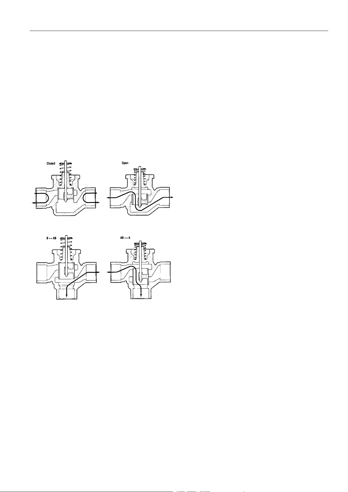
All moving and sealing parts of the valve are constructed in
the cartridge assembly.
The ports are sealed with ”O”-- rings on the outer surface of
the piston.
When the valve stem is driven down to open port A the water
will flow through the hollow piston to the other port.
In case of a 3--way valve with the piston driven down port B is
sealed, allowing flow between port AB and port A. With the
stem up the flow is between port AB and port B.
The VC series hydronic valves offer a variety of versions of
pipe connections to suit the different applications.
The valve pressure loss characteristic is dependent on the
pipe connection/dimensions
For the actual valve rating please refer to the specification
section.
Fig. 1.
Fig. 2.
2- way valve
When the valve reaches the fully open position the cam
closes switch SW
When the need for heat is satified, the controller contacts
and opens the switch SW2.
1
open, RLY1 is de-- energized and the valve motor driven
through SW
and the NC contacts of SW3.
1
When the valve reaches fully closed position, the cam closes
SW
and opens SW1. The valve is ready for the next call for
2
heat.
For both types of actuator a power failure will leave the valve
at the position it was interrupted.
When power is restored, the valve will respond to controller
demand.
3- way diverter valve
3- way diverter valve with an SPDT (3- wire) actuator
On a call for heat, the NO controller contacts close, the valve
closes port B and opens port A.
When port A is in the fully open position, the cam closes limit
switch SW
When the need for heat is satisfied the NC controller contacts
close, energizing the valve through SW
close.
When port A is fully closed the cam closes SW
SW
1
3- way diverter valve with an SPST (2- wire and common) actuator
On a call for heat, the controller contacts close, RLY
energized making the NO contacts in switch SW
port B to close and port A to open.
When port A reaches the fully open position the cam closes
switch SW
When the need for heat is satified, the controller contacts
open. RLY
and port A is driven closed through SW1 and the NC contacts
of SW
When port A is in the fully closed position, the cam closes
SW
2
heat.
For both types of actuator a power failure will leave the valve
at the position it was when interrupted.
When power is restored, the valve will respond to controller
demand.
and opens limit switch SW2.
1
causing port A to
1
and opens
2
. The valve is ready for the next call for heat.
is
1
causing
3,
and opens the switch SW2.
1
is de--energized making the NC contacts in SW
1
3.
and opens SW1. The valve is ready for the next call for
3
2- way valve with an SPDT (3- w ire) actuator
On a call for heat, the NO controller contacts close and the
valve opens. When the valve is fully open, the cam closes
switch SW
and opens switch SW2.
1
When the need for heat is satisfied the NC controller contacts
close, energizing the valve through SW
and closing the
1
valve.
When the valve is fully closed the cam closes SW
SW
. The valve is ready for the next call for heat.
1
and opens
2
2- way valve with an SPST (2- wire and common) actuator
On a call for heat, the controller contacts close, RLY1is
energized making the NO contacts in switch SW
causing the
3
valve to open.
Wiring
Fig. 3. and 4. show wiring connections for SPDT and SPST
controllers on either 2-- way valves or 3--way valves.
Port A ”open” and ”closed” denotes valve open and closed for
2-- way, and AB-- B open and AB--B open for 3--way valves
respectively.
Ona2--wayvalve:
Port A open denotes valve open
Ona3--wayvalve:
Port A open denotes flow through AB--A
Port A closed denotes flow through AB-- B
For mixed low/line voltage, the cable assembly version
recommended.
4
EN2R--9011 0108R2-- NE
Page 5
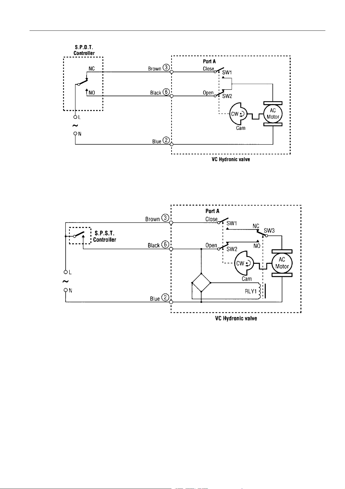
Fig. 3. Logic sequence diagram with 3 wire actuator for SPDT controller
Fig. 4. Logic sequence diagram with 2 wire + common actuator for SPST controller
5
EN2R--9011 0108R2-- NE
Page 6
SPECIFICATIONS
ext
ernally
threaded
E--externallythreade
d
Volt a g e Colour-- coded label
24 V, 50/60 Hz Blue
100 ... 130 V, 50/60 Hz Black
200 ... 240 V, 50/60 Hz Red
Power consumption
6 Watt maximum at nominal voltages (during valve position
change only)
6 VA for transformer and wiring
Maximum power time: 15%
Endswitchrating
2.2 A inductive from 5 ... 120 Vac
1.0 A inductive above 120 ... 277 Vac
Minimum dc switching capbility: 0.05A 24 Vdc
Nominal timing
Valve opens in 6 seconds @ 60 Hz (20% longer @ 50 Hz)
Table1.Pipefittingsizes
Pipe fitting sizes
Flare E E -- -- -- -- --
Inverted flare -- I -- -- -- -- --
Sweat -- N N N -- -- --
BSPP -- I E, I E, I -- -- --
BSPT -- I I -- -- -- --
NPT -- -- I I -- -- --
Compression fitting -- -- -- -- I E E
3/8” 1/2” 3/4” 1” 15 mm 22 mm 28 mm Note: N -- not threaded
Electrical termination
Molex
With integral 1000 mm (39”) leadwire cable
Pipe fitting sizes
Seetable1.
TM
Requires mating connector receptacle/housing
# 39-- 01 --2060
Contacts: Mini--Fit 5556 series
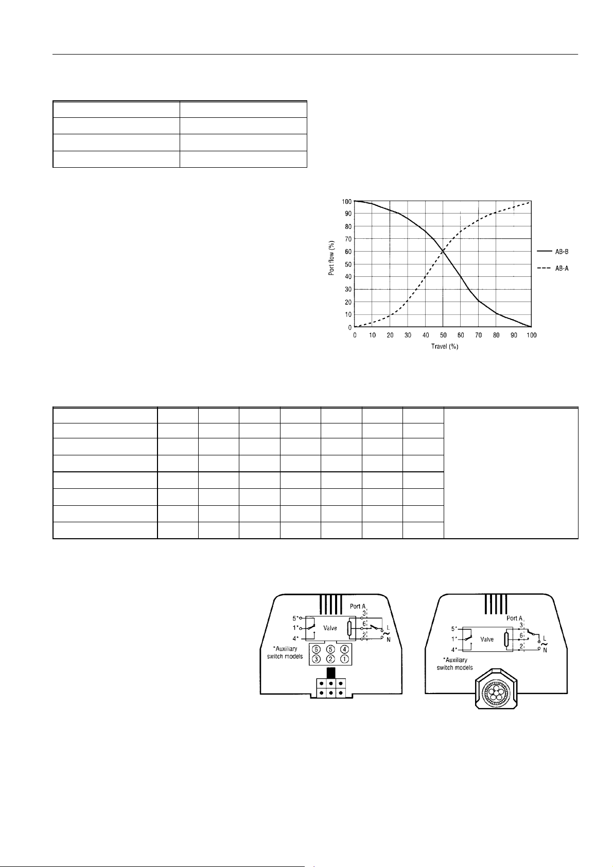
Fig. 5. 3--way valve diverting flow characteristic at
(header# 39--30--1060)
constant pressure on port AB
I -- internally threaded
E--
Terminal Action Wire colour
1Com* Orange
2 Neutral Blue
3Closed** Brown
4NO* Grey
5NC* White
6 Open** Black
* Terminals 1, 4 and 5 are only
connected if an auxiliary switch is used.
NO, NC refers to port A closed position
** Refers to port A (closed or open)
NOTE: For mixed voltages (low/line voltage)
thecableassemblyversionis
recommended
Fig. 6. Wiring terminal colour coding
MolexTMversion
6
Lead wire cable
EN2R--9011 0108R2-- NE
Page 7
Actuator type
3
/
3-- wire
(for SPDT controller)
2--wire + common
(for SPST controller)
Table 2. Wiring connections and valve movements
Connections 2-- way valve
Cable model MolexTMmodel
Blue & brown energized
Black de--energized
Blue & black energized
Brown de--energized
Blue & brown energized
Brown and black open
Blue & brown energized
Brown and black closed
Pin #2 & 3 energized
Pin #6 de --energized
Pin #2 & 6 energized
Pin #3 de --energized
Pin #2 & 3 energized
Pin #3 and 6 open
Pin #2 & 3 energized
Pin#3and6closed
movement movement
Closes A port closes
Opens B port closes
Closes A port closes
Opens B port closes
3-- way valve
Ambient temperature
0 ... 65 _C
Fluid temperature
1 ... 95 _C (120 _C short duration peak)
Shipping storage temperature
--40 ... 65 _C
Pressure rating
Static: 20 bar
Burst: 100 bar
Maximum operating pressure differential
4 bar
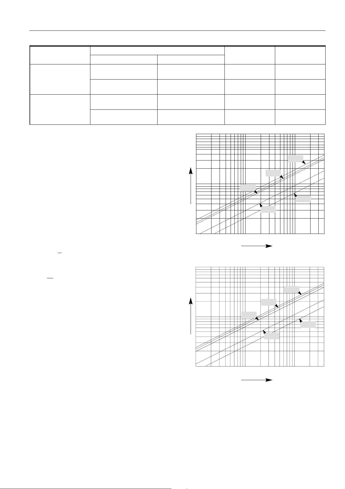
Flow rating
Dependent upon body configuration (see fig. 5., 7. and 8.)
Q
Kv
3
/h to be calculated as:
p(bar)
2
Flow rate Q m
Q = Kv × ∆
Pressure loss αp(bar)tobecalculatedas:
∆p =
Flow
2-way
Flow can be in either direction
Valve is closed without the actuator mounted
3-way
Flow can be diverting (AB to A or B) or mixing (A or B to AB).
Port A is closed without the actuator mounted
10
Kv 6,0
h)
Flow rate (m
1
Kv 5,0
Kv 5,3
Kv 2,1
Kv 3,0
0,1
0,001 0,01 0,1
bar
0,1 1 10kPa
Pressure loss
Fig. 7. Valve pressure loss characteristic for 2-- way valves
10
Kv 7,7
/h)
3
1
Kv 6,4
Kv 7,0
Kv 2,6
Flow rate (m
Kv 3,4
Valve material
Body: bronze
Cartridge: Ryton
”O”-- ring seals: EPDM rubber
Stem: stainless steel
Actuator cover: Noryl
Actuator base: Ryton
Noryl
TM
(polyphenylene sulphide)
TM
(polyphenylene oxide)
TM
(94V--0)
TM
(94V--0)
0,1
bar
0,001 0,01 0,1
kPa
0,1 1 10
Pressure loss
Fig. 8. Valve pressure loss characteristic for 3-- way valves
7
EN2R--9011 0108R2-- NE
Page 8

DIMENSIONS (NOMINAL)
Pipe fitting 2-- way valve 3-- way valve
Dim. C
mm
1
/2” Sweat 98 111 3.0 98 136 3.6
1
/2” BSPT (internal thread) 98 111 3.0 98 136 3.4
3
/8” flare (no adapter) 98 111 2.1 98 136 2,6
1
/2” flare (no adapter) 98 111 2.9 98 136 3.4
1
/2” inverted flare (no adapter) 98 111 3.1 98 136 3.6
1
/2” BSPP/15 mm (internal thread) 98 111 3.0 98 136 3.4
22 mm compression fitting* 112 113 5.3 112 140 7.1
3
/4” BSPP (external thread) 94 113 5.3 94 130 6.9
3
/4” BSPP (internal thread) 94 113 5.3 94 130 7.0
3
/4” BSPT (internal thread) 94 113 5.3 94 130 7.0
3
/4” NPT (internal thread) 94 11 3 5.4 94 130 7.4
3
/4” Sweat 94 113 5.0 94 132 6.4
28 mm compression fitting* 11 6 11 3 6.0 11 6 147 7.7
1” BSPP (internal thread) 94 113 6.0 94 136 7.7
1” BSPP (external thread) 94 11 3 6.0 94 136 7.7
1” NPT (internal thread) 94 11 3 6.0 94 136 7.7
1” Sweat 94 11 3 6.0 94 136 7.7
* Includes compression nuts and olives
Dim. D
mm
Nom. flow
rating -- Kv
Dim. C
mm
Dim. E
mm
Nom. flow
rating -- Kv
2--way valve 3--way valve
94 68 94 68
90 90
C
D
Fig. 9. Valve dimensions
8
E
AB
AB
C
EN2R--9011 0108R2-- NE
Page 9

VALVE SELECTION CHART
PACKAGING
Description Designation
Unit pack --
(10 per overpack)
SPECIAL
CUSTOMER
”C” CARTRIDGE
Kv Designation
00
Standard
Designation
3.0 10
3.2 10
2--way valves
Egg crate (20) E
(20 actuators per pack)
(10 body/cartidge(s)
01 ... 99
2.1 10
2.3 10
per pack)
Customer
special
3.1 10
3.0 10
assigned by
5.3 10
Note:
Order in multiples of 20
actuators & 20 valves
for egg crate pack.
Example:
A ”VC 4612 MM 6000” valve has a
200/240 V, 50/60 Hz, 6 second nominal
timing actuator (with a SPDT auxiliary
switch) for operation by a SPST
thermostat suitable for MolexTMconnection.
The valve has a 3--way body with 28 mm
compression fittings rated at 7.7 Kv & 60
psi differential.
Honeywell
5.3 10
5.3 10
5.3 10
5.4 10
5.0 10
6.0 10
6.0 10
6.0 10
6.0 10
6.0 10
6.0 10
3.6 60
2,6 60
3,4 60
3.6 60
3.4 60
7.1 60
6.9 60
7.0 60
7.0 60
7,4 60
6.4 60
7.7 60
3.4 60
7.7 60
7.7 60
7.7 60
7.7 60
7.7 60
Shipped in unit pack.
3--way valves
”B” BODY
”A” ACTUATORS
Description Designation
Description Designation
2--way valves
Nominal timing @ 50 Hz: 7 seconds
machined to accept 15 mm
* The valve end fittings are internally
connector 4612
TM
-- w i t h M o l e x
compression fittings.
** Compression fittings included
-- with 1000 mm cable 4613
” Flare (no adapter) AC
” Sweat AA
” BSPT (internal thread) AB
” Flare (no adapter) AD
” Inverted Flare (no adapter) AE
” BSPP (internal thread)* AF
” BSPP (external thread) AH
” BSPP (internal thread) AJ
” BSPT (internal thread) AK
” NPT (internal thread) AL
8
2
2
/
2
2
2
/
/
/
/
3
1
1
1
1
connector 2010
TM
-- with 1000 mm cable 2011
-- w i t h M o l e x
24 V (50 ... 60 Hz)
3wireforSPDTstat.
3 wire for SPDT stat.(w/SPDT aux. sw.)
/
1
connector 2610
TM
-- w i t h M o l e x
-- with 1000 mm cable 2611
22 mm Compression fitting** AG
3
2 wire + com. for SPST stat.
4
/
/
3
connector 8010
TM
-- w i t h M o l e x
” Sweat AM
4
4
4
4
/
/
/
3
3
3
28 mm Compression fitting** AN
1” BSPP (internal thread) AP
1” BSPP (external thread) AQ
1” NPT (internal AR
1” Sweat AS
connector 8610
TM
-- with 1000 mm cable 8011
-- w i t h M o l e x
-- with 1000 mm cable 8611
2 wire + com. for SPST stat. (w/SPDT aux. sw)
connector 6010
TM
-- with 1000 mm cable 6011
-- w i t h M o l e x
100 ... 130 V (50 ... 60 Hz)
3wireforSPDTstat.
1” BSPT (internal thread) AT
3 wire for SPDT stat. (w/SPDT aux. sw.)
” Sweat MA
” Flare (no adapter) MB
2
8
/
/
3--way valves
1
3
connector 6610
TM
-- w i t h M o l e x
-- with 1000 mm cable 6611
2 wire + com. for SPST stat.
9
” Flare (no adapter) MC
2
/
1
connector 4010
TM
-- w i t h M o l e x
” Inverted Flare (no adapter) MD
/
1
-- with 1000 mm cable 4011
” BSPP (internal thread)* ME
” BSPP (external thread) MG
” BSPP (internal thread) MH
” BSPT (internal thread) MJ
” NPT (internal thread) MK
” Sweat ML
2
2
4
4
/
1
22 mm Compression fitting** MF
4
/
/
/
3
/
3
3
3
connector 4610
TM
-- w i t h M o l e x
-- with 1000 mm cable 4611
2 wire + com. for SPST stat. (w/SPDT aux. sw.)
200 ... 240 V (50 ... 60 Hz)
3wireforSPDTstat.
4
4
/
3
connector 6012
TM
-- w i t h M o l e x
” BSPT (internal thread) MN
2
/
1
28 mm Compression fitting** MM
-- with 1000 mm cable 6013
3 wire for SPDT stat.(w/SPDT aux. sw.)
1” BSPP (internal thread) MP
1” BSPP (external thread) MQ
1” NPT (internal MR
1” Sweat MS
1” BSPT (internal thread) MT
connector 6612
TM
-- w i t h M o l e x
-- with 1000 mm cable 6613
connector 4012
TM
-- w i t h M o l e x
-- with 1000 mm cable 4013
2 wire + com. for SPST stat.
EN2R--9011 0101R1-- NE
2 wire + com. for SPST stat. (w/SPDT aux. sw.)
Page 10

INSTALLATION
IMPORTANT
Take care that installer is a trained experienced
service person.
When installing this product read these instructions
carefully.
Failure to follow them could damage the product or
cause a hazardous condition.
Check the ratings given in the instructions and on the
product to make sure it is suitable for your
application.
Always conduct a thorough checkout after
installation.
CAUTION
Switch off power supply before making electrical connections to prevent electrical shock and equipment
damage.
It is advisable to remove the actuator head from the
valve body for ease of installation.
Fit the actuator head in the most convenient position
for wiring.
On sweat fitted valves, the cartridge is shipped loose
or is removed to avoid being damaged during the
solder operation.
On 24 Volt systems, never short circuit the valve coil
terminals as this may burn out the heat anticipator in
the thermostat.
To remove the actuator head 25 mm clearance is
needed above the actuator.
Plumbing (see fig. 10.)
The valve may be plumbed in any angle but preferably not
with the actuator head below the horizontal level of the valve
body. Make sure there is enough room around the actuator
head for servicing or replacement.
When used to form a part of a central heating system, do not
locate it where it will block the system vent, cold feed or any
bypass when the valve is closed
Mount the valve directly in the tube or pipe. Do not grip
actuator head while making and thightening plumbing
connections. Either hold valve body in your hand or attach
adjustable spanner across the hexagonal or flat faces on the
valve body.
Compression models
For compression fitted models, tighten the compression nuts
enough to make a watertight seal.
Take care not to overtighten.
Maximum torque limit is 33 ft--lb for the 22 mm compression
fitting and 48 ft--lb for the 28 mm compression fitting.
Fig. 10. Plumbing
Sweat models
On sweat fitted valves, the cartridge is shipped loose to avoid
being damaged during the solder operation.
Remove valve actuator from body and solder the
connecting pipes in accordance with normal soldering
practices.
After soldering and valve has cooled, remove cartridge
assembly from plastic bag, insert into the valve body and
tighten down with enclosed wrench until it bottoms out. Do
not overtighten (maximum torque is 40 ft--lb).
The top surface of the cartridge will be flush with the top
edge of the body casting.
Replace valve actuator.
10
EN2R--9011 0108R2-- NE
Page 11

To install a replacement actuator head
IMPORTANT
Installation of a new actuator head does not require
draining the system providing the valve body and
cartridge assembly remain in the pipe line.
Disconnect power supply before servicing to avoid
electrical shock or equipment damage.
Disconnect leadwires to actuator head, or depress
tabonMolex
TM
connector and remove.
Where appropriate, label wires for rewiring.
The actuator head is automatically latched to the valve
(see fig. 11.) To remove lift up on the latch mechanism
located directly below the red manual open lever.
Press the actuator head down towards the valve body with
moderate hand force and turn counter--clockwise by
turn (45 degrees) simultaneously.
1
/
8
Lift the actuator head off the valve body.
NOTE: The actuator can also be installed at right angles
to the valve body but in this position the latch
mechanism is not engaged.
Install the new actuator head by reversing the process.
Reconnect leadwires or Molex
TM
connector.
Restore power.
Fig. 11. Latch mechanism
11
EN2R--9011 0108R2-- NE
Page 12

ADJUSTMENT, CHECKOUT AND SERVICE
Manual opener
The manual opener can be manipulated when in the up
position.
The motorized valve can be opened by firmly pushing the red
manual lever down to midway and in (only possible if the
actuator is in the upper position).
This holds all ports in the open position and with auxiliary
switch models the NO switch is closed.
Ports A and B of 3--way valves are opened.
This ”manual open” position may be used for filling, venting or
draining the system or for opening the valve in case of power
failure. The valve can be restored manually to the closed
position by depressing the red manual lever ligthly and then
pulling it out.
The valve actuator returns to the automatic position when
power is restored.
Checkout
Raise the setpoint of the thermostat above room
temperature to initiate a call for heat.
Valve position indicator should move downward to the
open position.
For all auxiliary switch models, monitor the control devices.
2--way valve:
check that the valve opens, the auxiliary switch (if
present) closes and at the end of the opening
stroke the circuit to the circulator or another valve
is made.
3--way valve:
check that port A opens, port B closes, the
auxiliary switch (if present) operates and at the
end of the opening stroke the circuit to the
circulaotr or another valve is made.
Lower the set point of the thermostat below room
temperature.
Observe the control devices.
2--way valve:
check that the valve closes and all auxiliary
equipment stops.
3--way valve:
check that port A closes and all auxiliary
equipment stops.
Service
WARNING
The VC series hydronic valves should be serviced by
trained, experienced service personnel.
If the valve is leaking, drain system or isolate valve from
the system.
Check to see if the cartridge needs to be replaced.
If the gear train of the motor is damaged, replace the
actuator assembly.
NOTE: The VC series hydronic valves are designed and
tested for silent operation in properly designed and
installed systems.
However, water noises may occur as a result of
excessive water velocity.
Piping noises may occur in high temperature
(over 100 _C) systems with insufficient water
pressure.
12
EN2R--9011 0108R2-- NE
Page 13

QUALITY ASSURANCE STATEMENT
The quality system is described in Honeywell Limited’s Quality
Manual and supporting operational procedures and
instructions.
The quality system is approved by Quality Management
Institute (accredited by the Standards Council of Canada and
RvC) against certificate 001082 and is reviewed annually.
The quality organisation is responsible for defining,
maintaining, improving and verification of the quality systems
in the field of design, production process and field quality
service.
Each production operation has manufacturing instructions
containing work procedures, set--up information, quality
standards and quality checks.
All products are tested prior to shipping.
Assembly inspection is conducted by the assembly workers.
All inspections (incoming and assembly) are performed by
trained personel and according inspection procedures.
13
EN2R--9011 0108R2-- NE
Page 14

STANDARDS AND APPROVALS
Approvals
The VC series balanced hydronic valves 200 ... 240 V and
24 V versions meet the Low Voltage Directive 73/23/EEC
(EN 60730 --1 and -- 2 -- 8) and EMC Directive 89/336/EEC for
incorporation in household electrical applications according to
EN 60335 series.
14
EN2R--9011 0108R2-- NE
Page 15

ORDERING INFORMAT ION
Before ordering p lease determine the following:
The body type:
2-- way or 3-- way. See Valve selection chart page 9
The actuator voltage:
24, 100 ... 130 or 200 ... 240 Vac. See Valve selection
chart page 9
Thepipefittingsize:
to do this first determine the flow rating (Kv) required.
Refer to Dimensions page 6 to select the pipe fitting
that is applicable.
Then, contact your Honeywell account manager who will
assist you in determing the order specification number.
VC
4013
Product family specifier
Actuator specifier
-- the first digit denotes a standard
Honeywell control circuit series.
-- the second, third and fourth digits
denote actuator and termination
variations
Order from:
Your nearest Honeywell branch office.
Your local Honeywell agent or wholesaler.
NOTE: Most models of valves and replacement components
MG 60
will be available under ”TRADELINE” label.
Ask your wholesaler for details.
E00
Accessories and packing specifier
-- this letter denotes the packaging and
accessory configurations for complete
devices and merchandised items
Customizing specifier
-- expresses variations in a valve
configuration which consists of a
product family, actuator, body and
cartridge
-- 00 is standard configuration
Body specifier
-- a first letter from A to L denotes 2--way
operation, whereas M to Z denotes
3-- way operation
-- the second letter accommodates
first letter variations
Cartridge specifier
-- a number from 10 to 59 denotes
2-- way operation, whereas 60 to 99 de
notes 3--way operation.
Fig. 12. Model number chart
15
EN2R--9011 0108R2-- NE
Page 16

STANDARD PRODUCT EXAMPLES
NOTE: The letter ”Z” denotes the absence of a component
VC2010MG 6000
VC2010 actuator packed with a MG6000 body
VC2010ZZ 00E
Egg crate with 20 actuators type 2010
VC Z MG6000E
Egg crate with 10 bodies type MG6000
VC2010ZZ00
Actuator only
VC ZZ 6000
Cartridge for 3-- way valve
Minimum quantity 10 pcs
VC ZZ 1000
Cartridge for 2-- way valve
Minimum quantity 10 pcs
16
EN2R--9011 0108R2-- NE
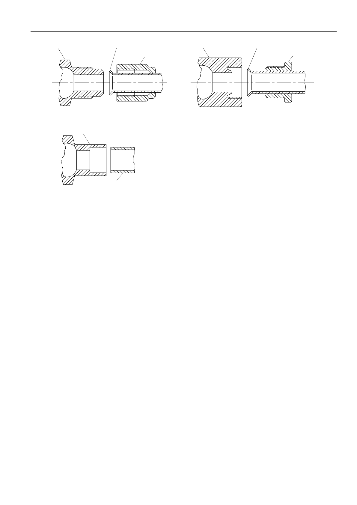
Page 17

FITTINGS FOR 1/2” AND 15 MM VALVE FAMILY (COMMONLY USED WITH VC VALVES)
46.0
Valve body
98.0
A
B
AB
Fig. 13. Finished dimensions of 1/2” or 15 mm bronze bodies (VC valves)
Metal flange
Gasket
Pipe is soldered or threaded into metal
flange (solder joint shown)
Fig. 14. 1/2” BSPP external (G 1/2 B)
Loose brass nut
98.0
A
B
Valve body Pipe has paralel threads
Fig. 16. 1/2” BSPP internal (Rp 1/2”)
Valve body Loose brass nut
Valve body
North America 1/2”pipe (5/8” outer diameter)
Pipe has 45_ flare
Loose nut
Fig. 15. 1/2” flare
Loose ferrule (compression ring)
Fig. 17. 1/2” BSPP internal (Rp 1/2”) using ferrule & nut
for sealing 15 mm outer diameter pipe
17
EN2R--9011 0108R2-- NE
Page 18
Valve body
V
Pipe has 45_ flare
Loose nut
Valve body
Pipe has 45_ flare
Loose nut
For North America 3/8”pipe (1/2” outer diameter)
Fig. 18. 3/8” flare
alve body
Pipe is sweat soldered into valve body
North America 1/2” pipe sweat fitting
Fig. 19. 1/2” Sweat
For North America 1/2” pipe (5/8” outer diameter)
Fig. 20. 1/2” inverted flare
18
EN2R--9011 0108R2-- NE
Page 19
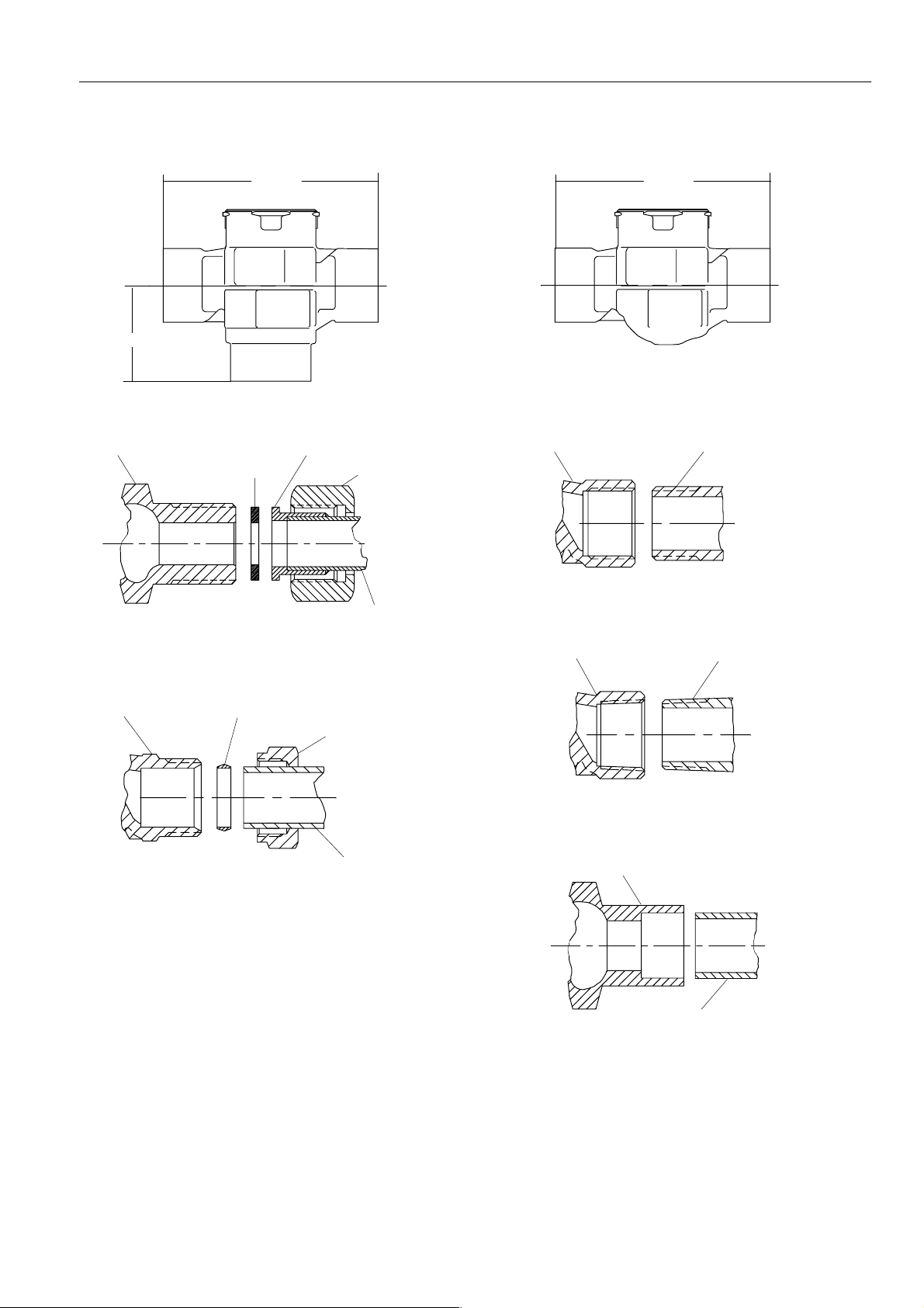
FITTINGS FOR 3/4” AND 22 MM VALVE FAMILY (COMMONLY USED WITH VC VALVES)
93.2 93.2
’B’
Valve body
1)
’B’ = 39.9
Valve body
A
B
AB
1)
Fig. 21. Finished dimensions of 3/4” or 22 mm bronze bodies (VC valves)
Metal flange
Gasket
Pipe is soldered or threaded into metal
flange (solder joint shown)
Fig. 22. 3/4” BSPP external (G 3/4 B)
Loose ferrule (olive) *
Loose brass nut *
Loose brass nut
1)
’B’ = 39.9
A
Valve body
Fig. 24. 3/4” BSPP internal (Rp 3/4)
Valve body
Pipe has tapered threads
B
Pipe has parallel threads
Pipe is slip fit into valve body
Using ferrule and nut for sealing 22 mm outerdiameter pipe.
1)
’B’ = 39.9
* Compression nut and olive are supplied with the valve
body.
Fig. 23. 22 mm compression (external thread)
1)
’B’= 39.9
Fig. 25. 3/4” BSPT internal (Rc 3/4) or NPT internal
Valve body
Pipe is sweat soldered into
1)
’B’ = 42
North America 3/4” pipe sweat fitting
19
valve body
Fig. 26. 3/4” Sweat
EN2R--9011 0108R2-- NE
Page 20
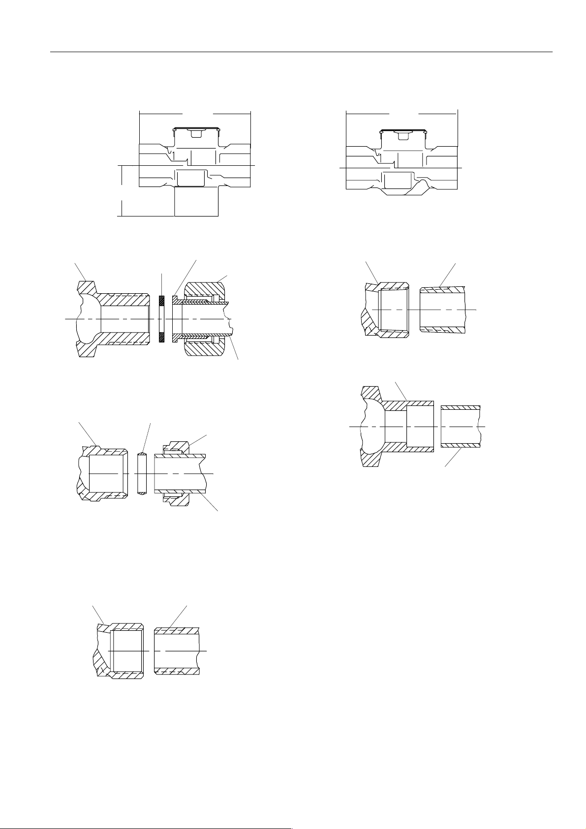
FITTINGS FOR 1” AND 28 MM VALVE FAMILY (COMMONLY USED WITH VC VALVES)
Valve body
93.2
A
B
AB
45.5
Fig. 27. Finished dimensions of 1” or 28 mm bronze bodies (VC valves)
Metal flange
Gasket
Pipe is soldered or threaded into metal
flange (solder joint shown)
Fig. 28. 1” BSPP external (G 1 B)
Loose brass nut
93.2
A
Valve body
Fig. 31. 1” BSPT internal (Rc 1) or 1” NPT internal
Valve body
B
Pipe has tapered threads
Valve body
Using ferrule and nut for sealing 28 mm outerdiameter pipe.
* Compression nut and olive are supplied with the valve
body.
Fig. 29. 28 mm compression (external thread)
Valve body
Fig. 30. 1” BSPP internal (Rp 1)
Loose ferrule (olive) *
Loose brass nut *
Pipe is slip fit into valve body
Pipe has parallel threads
Pipe is sweat soldered into valve body
Fig. 32. 1” Sweat
20
EN2R--9011 0108R2-- NE
Page 21

ACCESSORIES
Replacement cartridge (includes change tool)
Cartridge for 2- way valve
-- order number: VCZZ1000
-- supplied in overpacks of 10 units
Cartridge for 3- way valve
-- ordernumber: VCZZ6000
-- supplied in overpacks of 10 units
MolexTMconnector with wires
CAUTION
Not to be used for line voltage or mixed low/line
voltage applications.
TM
3-wire Molex
-- ordernumber: 40.007.035-- 001
6-wire MolexTMconnector, length 5”
-- ordernumber: 40.007.035-- 002
3-wire MolexTMconnector, length 1000 mm
-- ordernumber: 40.007.035-- 005
connector, length 5”
Home and Building Control
Combustion Controls Center Europe
Honeywell BV
Phileas Foggstraat 7
7821 AJ Emmen
The Netherlands
Tel: +31 (--)591 695911
Fax: +31 (--)591 695200
http://europe.hbc.honeywell.com
21
EN2R--9011 0108R2-- NE
 Loading...