

Page 1
62-0197-04
VBN2, VBN3
CAUTION
CAUTION
85 85
M29519A
Control Ball Valve/Actuator
Assemblies
INSTALLATION INSTRUCTIONS
INSTALLATION
When Installing this Product...
1. Read these instructions carefully. Failure to follow
them could damage the product or cause a
hazardous condition.
2. Check ratings given in the product data literature
and on the product to ensure the product is suitable for your application.
3. Installer must be a trained, experienced, licensed
service technician.
4. After installation is complete, check out product
operation as provided in these instructions.
Preparation
Equipment Damage Hazard.
Foreign particles like dirt and metal chips can
damage the ball seals.
Clean upstream lines prior to installation.
Equipment Damage Hazard.
Improper chemicals can damage the valve.
Use neither aerosol products nor petroleumbased lubricants.
1. Clean the lines upstream of particles larger than
1/16 in. diameter. Open valves fully. Flush entire
hydronic system of contaminants (welding slag,
solder, scale, metal chips, etc.) and chemically
treat water according to local conditions prior to
operation.
2. Proceed with installation once the system specifics
(expansion/contraction of the system and its
medium as well as operating pressures) are within
tolerances.
3. Eliminate air from system.
4. Two-way valves are marked to show flow direction.
IMPORTANT
Flow arrows must point in the direction of the
flow for proper operation.
NOTE: For three-way valve mounting, see Fig. 3
through 5.
5. Stem rotation:
a. For two-way valves:
(1) Clockwise to close.
(2) Counterclockwise to open.
b. For three-way valves:
(1) Clockwise to increase B to AB flow.
(2) Counterclockwise to increase A to AB flow.
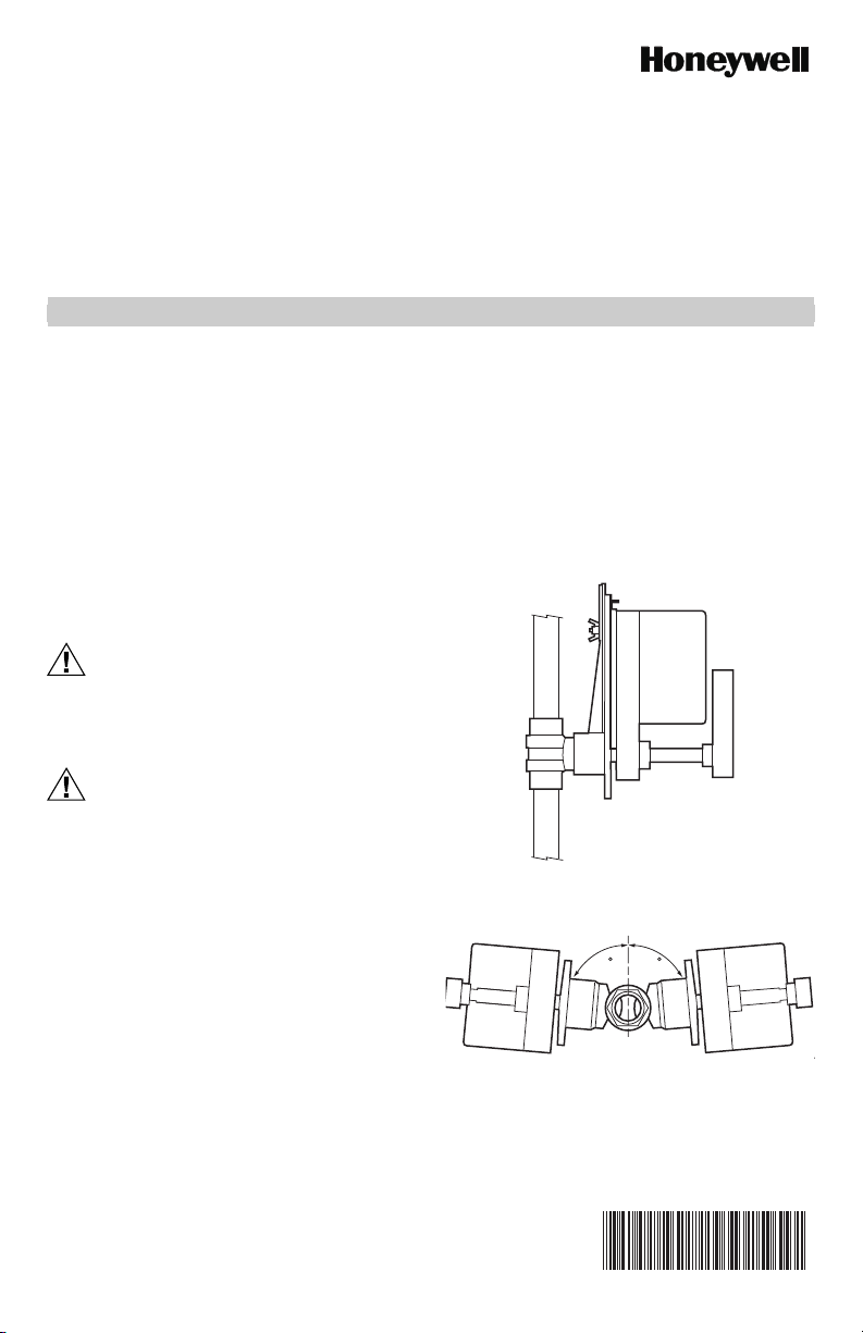
6. Valve must be mounted with the actuator/bracket
above the valve body. Do not install the valve with
the stem below horizontal or upside down. (See
Fig. 1 and 2.)
M29518
Fig. 1. Vertical valve installation.
Fig. 2. Acceptable valve angle from vertical.
Page 2
VBN2, VBN3 CONTROL BALL VALVE/ACTUATOR ASSEMBLIES
See Fig. 8 and 9 for valve dimensions. Refer to actuator
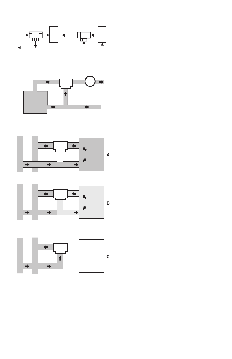
AB PORT A PORT
SUPPLY
RETURN
Fig. 3. Three-way ball valve flow orientation
BOILER
COIL
B PORT
(not to scale).
RETURN
VBN3
A AB
B
AB PORT A PORT
SUPPLY
MIXINGDIVERTING
B PORT
COIL
M13737
PUMP
M29517
literature for actuator dimensions.
Mounting Plate Adjustment
The Actuator Mounting Plate can be rotated to a different
position for installation in confined spaces. This is
accomplished as follows:
1. Remove the handle from the shaft and set it aside.
2. Remove the two screws that hold the stem
3. Remove and set aside the stem assembly.
4. Remove and set aside the two screws that attach
5. ENSURE VALVE IS ISOLATED AND DEPRES-
Fig. 4. Reset mixing control for discharge hot water.
FULL
HEAT
AB A
VB3
B
5 GPM
PROPORTIONED
HEAT
AB A
VB3
B
2.5 GPM
RETURN
MAIN
5 GPM
AB
VB3
B
5 GPM
5 GPM
with coil bypass.
SUP PL Y
MAIN
NO
HEAT
Fig. 5. Three-way mixing valve operation
A
HEATING COIL
5 GPM
2.5 GPM
NO FLOW
THROUGH COIL
M19523
Mechanical Installation
The valveshave female NPT pipe fittings and should be
sealed with an approved pipe sealant or tape. Take care
not to use excess pipe dope to avoid interfering with
operation of ball. Torque should not exceed 75 ft-lb.
6. Rotate mounting plate around valve top to the
IMPORTANT
7. Lower ring down to valve body and engage it in the
8. Tighten screws to valve body securing the mounting
9. Reattach the stem assembly to the mounting plate.
10. If desired, replace the handle on the shaft.
NOTE: See Fig. 6 for valve exploded view.
IMPORTANT
Electrical Installation
1. If necessary, remove actuator wiring cover.
2. Wire the actuator according to the appropriate
3. If applicable, position reverse/direct acting switch
4. Replace cover.
assembly to the mounting plate and set them aside.
the mounting plate to the valve.
SURIZED BEFORE PROCEEDING. Remove yellow pressure plate marked “HIGH PRESSURE”
from valve bonnet, rotate 90° or 180°, and re-install
screws using same holes in pressure plate and the
appropriate pair of tapped holes in the valve bonnet.
NOTE: Take note of the screw hole positions on
the valve. They limit the mounting plate
positions.
desired position.
Do not rotate the valve stem while the hold-down
ring is removed. This can change the common
port from AB to A.
new position relative to the mounting plate.
plate.
After adjusting a three-way valve mounting plate,
take note whether the AB port or the A port is the
common port.
diagram provided with actuator or job specifications. For detailed actuator information, see Honeywell literature:
— 62-0274—MS7505/MS8105 Spring Return
Actuator Installation Instructions
— 63-2632—MN6105 Floating Actuator
Product Data
— 63-2633—MN7505 Modulating Actuator
Product Data
— 63-2209—ML6161/ML6164/ML7161/ML7164
Non-spring return direct Coupled Actuators
Product Data
for desired operation.
62-0197—04 2
Page 3

VBN2, VBN3 CONTROL BALL VALVE/ACTUATOR ASSEMBLIES
HANDLE (REMOVABLE) FOR
MANUALLY ROTATING SHAFT
SCREWS (2)
STEM ASSEMBLY COVER
STEM ASSEMBLY
SCREWS (2)
VALVE STEM
COUPLER
STEM RETAINER PLATE
VALVE BODY
1
1
ANTI-ROTATION
BRACKET
1
WING NUT
MOUNTING
PLATE
1
1
BOLT
1
1
BOLT
1
ANTI-ROTATION
BRACKET
2
1
1
OPERATION AND CHECKOUT
Once both the mechanical and electrical installations are
complete:
1. Cycle the actuator to verify that the direction of rotation suits the control sequence.
2. If the rotation direction is incorrect:
a. For 2-position control actuators: Remount actu-
ator on the bracket.
b. For floating control actuators: Reverse two con-
trol signal wires (CW/CCW).
c. For analog control actuators either:
(1) Reposition reverse/direct acting switch, or
(2) Remount actuator on the bracket.
3. If the control scheme requires fail-safe operation,
ensure that, upon removal of power, the valve
rotates to the desired position.
4. Spring return actuators are factory-configured for
A-port normally-closed fail-safe operation. To
change this to normally-open, remove and reinstall
the actuator in the opposite orientation as follows:
(a) Loosen the shaft coupling bolt using a 10
mm wrench.
(b) Loosen all other mounting bolts connect-
ing the actuator to the mounting bracket,
and set aside.
(c) Remove the actuator from the valve
shaft.
(d) Move the actuator shaft coupling to the
opposite side of the actuator, as displayed
in Figure 7.
1
INCLUDED IN REPLACEMENT KIT (PART NO. 5112-11).
2
THIS PART USED WITH NON-SPRING RETURN ACTUATORS.
Fig. 6. Valve assembly exploded view.
M29526
M27714
Fig. 7. SCSA Mounting
For detailed actuator information, see Honeywell forms:
— 63-2209 ML6161,ML7161 Product Data Sheet.
— 63-2607 S05,S10,S20 Series Actuator Product Data
Sheet.
3 62-0197—04
Page 4

VBN2, VBN3 CONTROL BALL VALVE/ACTUATOR ASSEMBLIES
F
B
E
A
C
D
PIPE SIZE Cv DIMENSIONS IN INCHES (mm) WEIGHT REPLACEMENT
CODE DESIGNATORS
(DN)
VBN2A...
15
1/2
3/4
1
1-1/4
1-1/2
2
2-1/2
3
B,D,E,F,G,H,K
J 2-5/8 (67)
VBN2B...
20
B,D,E,G,H,J,L
K,M
VBN2C...
25
J
HLP 3-1/16 (78)
M,N 4-5/16 (109)
VBN2D...
30
H,J,K,L,N
M,S 3-5/8 (92)
VBN2E...
40
L,M,R
N,1 4-1/16 (103)
VBN2F...
50
N,T
P,R,S,1,2 4-15/16 (125)
VBN2G...
65
N,P,R,S,U,1
VBN2H...
80
N,P,R,T,U
INDICATES FULL PORT VALVE: NO FLOW CHARACTERIZING INSERT.
1
WILL BE SHORTER WITH NON-SPRING-RETURN ACTUATORS.
2
A
2-3/8 (60)
1
1
2-3/4 (70) 7-1/16 (179)
1
1
1
3 (76) 3-1/8 (79)
1
1
3-7/16 (87)
1
4 (102)
1
1
5-5/16 (135)
1
5-3/4 (146)
1
B
C D E F LB (KG)
2-3/4 (70)
6-5/8 (168)
2-7/8 (73)
6-1/2 (165)
2-3/4 (70)
6-7/16 (163)
2-7/8 (73)
6-1/2 (165)
3-1/16 (78)
6-3/4 (171)
3-1/4 (82)
7-3/8 (187)
6-11/16 (170) 3
3-1/4 (82)
7 (178)
6-15/16 (176)
3-3/4 (95)
7-1/16 (180)
7-3/16 (183)
4-1/16
7-7/16 (189)
(103)
7-9/16 (192)
7-11/16 (195)
(76)4(102)
2
8-1/8 (206)
8-5/16 (211)
8-1/8 (206) 1.0 (0.5)
8-5/16 (211)
8-11/16 (221) 1.4 (0.6)
8-7/8 (225)
8-11/16 (221)
9-1/16 (230)
8-7/8 (225)
10-1/2 (267)
10-11/16 (271)
Fig. 8. VB2 dimensions in inches (mm).
B
G
A
C
PIPE SIZE Cv WEIGHT REPLACEMENT
IN.
(DN)
CODE DESIGNATORS
1/2
3/4
1
1-1/4
1-1/2
2
2-1/2
B,D,E,F,H,J
15
VBN2A...
20
VBN2B...
25
VBN2C...
30
VBN2D...
40
VBN2E...
50
VBN2F...
65
VBN2G...
INDICATES FULL PORT VALVE: NO FLOW CHARACTERIZING INSERT.
1
3-1/2 (89)
C,D,E,F,G,K
2-13/16 (71)
1
3-13/16 (97)
C,D,E,F,G
3 (76)
J,L
4-5/16 (110)
H,K,M
1
H,J,L
3 (76) 3-13/16 (97)
K,M,N 3-5/8 (92)
1
1
H,J,K,M
4-5/16 (110) 7-13/16 (198) 10-13/16 (275)
4 (102)
L,P
L,N,P
R,T 5 (127)
P,R , S ,
1
E D
DIMENSIONS IN INCHES (mm)
B
A
CDEF GLB(KG)
7 (178)
6-1/2 (165)
3-5/16 (84)
7-5/16 (186) 9-1/2 (241)
3-13/16 (97)
6-13/16 (173)
4 (102)
7-13/16 (198)
6-13/16 (173) 3
4 (102)
7-5/16 (186)
4-1/2 (114)
7-5/16 (186)
5-13/16 (148)
7-13/16 (198)
(76)4(102)
9-3/8 (238)
8-13/16 (224)
9-13/16 (249)
10-13/16 (275)
9-13/16 (249)
10-5/16 (262)
11 (279)
12-5/16 (313)
2 (51) 2.4 (1.1)
2-1/16 (52)
2-7/16 (62)
3-1/8 (79)
2-13/16 (71)
2-7/16 (62)
2-3/4 (70)
3-3/16 (81)
3-1/8 (79)
3-7/8 (98)
4-1/8 (105)
Fig. 9. VB3 dimensions in inches (mm).
Automation and Control Solutions
Honeywell International Inc. Honeywell Limited-Honeywell Limitée
1985 Douglas Drive North 35 Dynamic Drive
Golden Valley, MN 55422 Toronto, Ontario M1V 4Z9
http://customer.honeywell.com http://customer.honeywell.ca
® U.S. Registered Trademark
© 2010 Honeywell International Inc.
62-0197—04 E.K. Rev. 04-10 Printed in U.S.A.
2.4 (1.1)
1.4 (0.6)
2.4 (1.1)
3.2 (1.5)
2.0 (0.9)
2.8 (1.3)
2.6 (1.2)
3.3 (1.5)
2.4 (1.1)
2.8 (1.3)
3.3 (1.5)
3.8 (1.7)
ASSEMBLYIN.
5112-19
5112-22 (SS)
5112-20
5112-23 (SS)
5112-21
5112-24 (SS)
F
STEM ASSEMBLY
5112-19
5112-20
5112-21
STEM
M31359
M31360
 Loading...