

Page 1
VBF5011, VBF5013 Control Ball
Valves With Flanged Connections
INSTALLATION INSTRUCTIONS
APPLICATION
The VBF5011 Two-Way and the VBF5013 Three-Way
Control Ball Valve control hot and chilled water with glycol
solutions up to 50% in heating, ventilating and air
conditioning (HVAC) systems to provide two-position or
modulating functions.
These valves can be used with Honeywell electronic
actuators.
Application Notes
IMPORTANT
Valve sizing is important for correct system operation. Undersized valves do not have sufficient
capacity at maximum load. Oversized valves do not
have sufficient authority over the load in modulating applications. Oversized valves can cause
excessive cycling and the seat and ball can be
damaged because of the restricted opening.
Proper Use
These valves are only for use in cold, warm, and hot water
systems. Not suitable for oil or combustible gases. For
water application, they are designed for a medium
temperature range from -22 to 250°F, at a maximum
pressure of 360 psi for 2-1/2" & 3" valves and 240 psi for
4", 5", & 6" valves. The valves are to be operated with the
appropriate Honeywell electronic actuators only. Water
should be properly filtered, treated and conditioned
according to local conditions and the recommendations of
the boiler or chiller manufacturers. The installation of
strainers and filters is recommended.
IMPORTANT
The presence of excessive iron oxide (red rust) in
the system voids the valve warranty.
Required Torque
Honeywell electronic actuators can be utilized with the
VBF5011 and VBF5013 valves. See Table 1, which lists the
torque requirement for each valve size. See Table 2, which
lists the close-off pressure rating for the valves with the
different torque actuators. Larger torque actuators may be
used, but there is no increase in close-off pressure rating.
Table 1. Torque Requirement
Torque Requirement
Type Size
2-way 2 1/2” 35
3” 35
4” 85
5” 85
6” * 140
3-way 2 1/2” 35
3” 85
4” 85
5” 85
6” * 140
*6" requires 140 in-lb actuator for flows up to 700 gpm.
For flow rates greater than 700 gpm a 200 in-lb actuator is recommended.
Table 2. Close-off Pressure Rating
Actuator Type
35 lb-in
Valve
Type
2-way 2-1/2”, 3”100
3-way 2-1/2” 40
3-way 3” 70 70 70 70
2-way,
3-way
2-way,
3-way
2-way,
3-way
Valve
4” 70 70 70 70
5” 70 70 70 70
6” 70 70
(4 Nm)
Size
88 lb-in
(10 Nm)
Close-off pressure rating (psi)
175 lb-in
(20 Nm)
(in-lbs)
175 lb-in
(20 Nm)
2-position
300 lb-
in (34
Nm)
Flow Characteristics
VBF5011 Two-Way Control Ball Valves have:
• an equal percentage flow characteristic.
VBF5013 Three-Way Control Ball Valves have:
• between ports A and AB: an equal percentage flow
characteristic.
• between ports B and AB: a linear flow characteristic.
62-2035-02
Page 2
VBF5011, VBF5013 CONTROL BALL VALVES WITH FLANGED CONNECTIONS
CAUTION
M34652
D
H
C
B
A
E
G
F
INSTALLATION
When Installing this Product...
1. Read these instructions carefully. Failure to follow
them could damage the product or cause a hazardous condition.
2. Check ratings given in instructions and on the prod-
uct to ensure the product is suitable for your application.
3. Installer must be a trained, experienced service
technician.
4. After installation is complete, check out product
operation as provided in these instructions.
Preparation
Safety
The valves are to be installed by skilled personnel and in
strict accordance with the installation instructions and
local regulations. Honeywell assumes no responsibility for
damages or injuries resulting from non-compliance with
installation instructions or standard good practice when
mounting, operating, or maintaining the valves, even if not
explicitly mentioned in the installation instructions.
Observe all safety practices.
Equipment Damage Hazard.
Foreign particles like dirt and metal chips can
damage the ball seals.
For trouble-free operation of the product, good
installation practice must include initial system
flushing and chemical water treatment. Clean the
lines upstream of particles larger than 1/16 inch
diameter (welding slag, pipe scale, sand and other
suspended particulate). Use of a 20 mesh system
side stream filter is suggested. Remove all filters
before flushing.
Do not use boiler additives, solder flux and wetted
materials which are petroleum based or contain
mineral oil, hydrocarbons or ethylene glycol
acetate. Compounds which can be used, with
minimum 50% water dilution, are diethylene
glycol, ethylene glycol, and propylene glycol
(antifreeze solutions).
If installing these valves in an addition to, or
retrofitting an existing building, do not assume
that the fluid in the existing piping meets these
criteria.
IMPORTANT:
1. Hold valve with pipe wrench by hexagonal fitting
ONLY. Do NOT handle the valve body with the pipe
wrench; product damage may result.
2. Clean the lines upstream of particles larger than
1/16 in. diameter (welding slag, pipe scale and
other contaminants).
3. Proceed with installation once the system specifics (expansion/contraction of the system and its
medium as well as operating pressures) are within
tolerances.
4. Eliminate air from system.
5. All the valves are marked to show proper direction.
6. Flow arrows must point in the direction of the flow
for proper operation. If the valves are not installed
in the correct orientation, improper flow or possible system damage could occur.
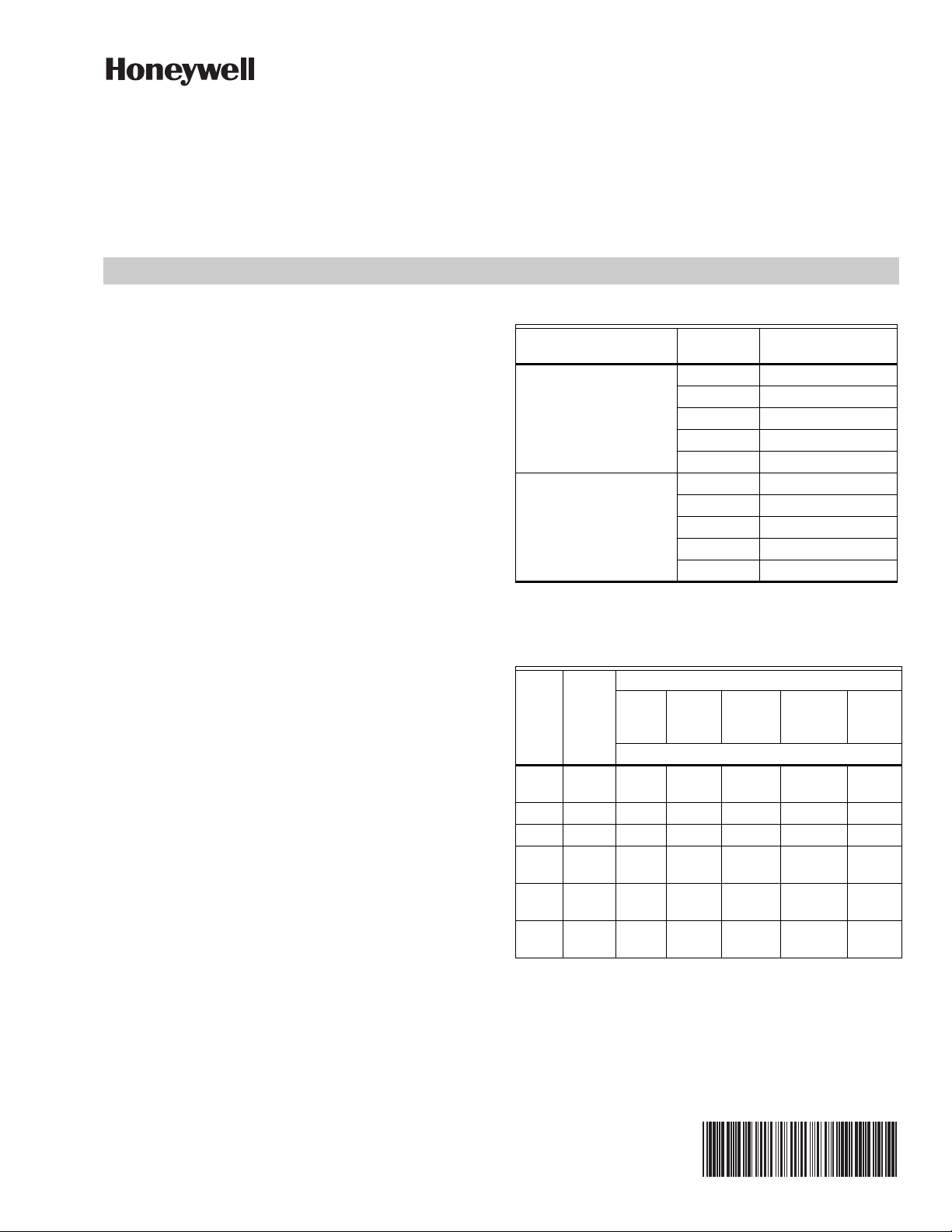
Fig. 1. 2-way 2-1/2" & 3" valve dimensions
Table 3. 2-way 2-1/2" & 3" valve dimensions
Size in. Model Number A in. (mm) B in. (mm) C in. (mm) D in. (mm) E in. (mm) F in. (mm) G in. (mm) H in. (mm)
2-1/2 VBF5011A1734/U 9-1/2 (241) 7 (178) 12-3/8 (314) 8-3/4 (222) 4-5/16 (110) 5-1/2 (140) 3/4 (19) 3 (76)
3 VBF5011A1767/U 11 (279) 7-1/2 (191) 12-5/8 (321) 9 (229) 6 (152)
62-2035—02 2
Page 3
VBF5011, VBF5013 CONTROL BALL VALVES WITH FLANGED CONNECTIONS
M34653
A
C
D
F
I
B
G
E
H
M34656
H
D
C
I
A
B
E
G
F
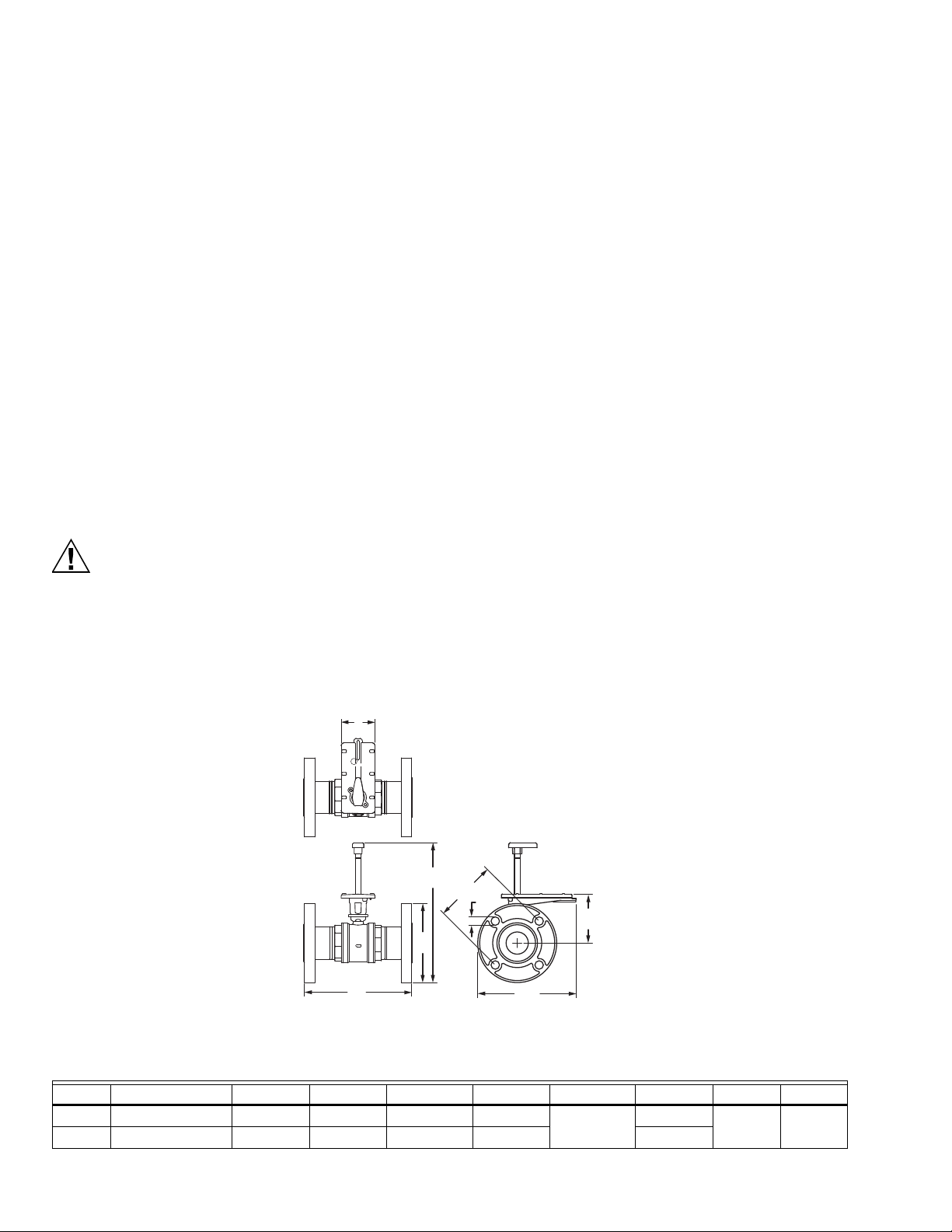
Fig. 2. 3-way 2-1/2" valve dimensions
Fig. 3. 3-way 3" valve dimensions
Size
in. Model Number
2-1/2 VBF5013B1003/U 9-1/2
(241)
3 VBF5013B1011/U 11
(279)
Table 4. 3-way 2-1/2" & 3" valve dimensions
A
in.
(mm)
B
in.
(mm)
7
(178)
7-1/2
(191)
C
in.
(mm)
15-5/16
(389)
13-1/8
(333)
D
in.
(mm)
8-3/4
(222)
10-5/16
(262)
3 62-2035—02
E
in.
(mm)
4-5/16
(110)
4-13/16
(122)
F
in.
(mm)
5-1/2
(140)
6
(152)
(mm)
3/4
(19)
G
in.
H
in.
(mm)
6-7/16
(164)
6-5/8
(168)
I
in.
(mm)
3
(76)
Page 4
VBF5011, VBF5013 CONTROL BALL VALVES WITH FLANGED CONNECTIONS
F
G
H
M34655
B
A
D
C
E
F
E
B
A
D
C
M34654
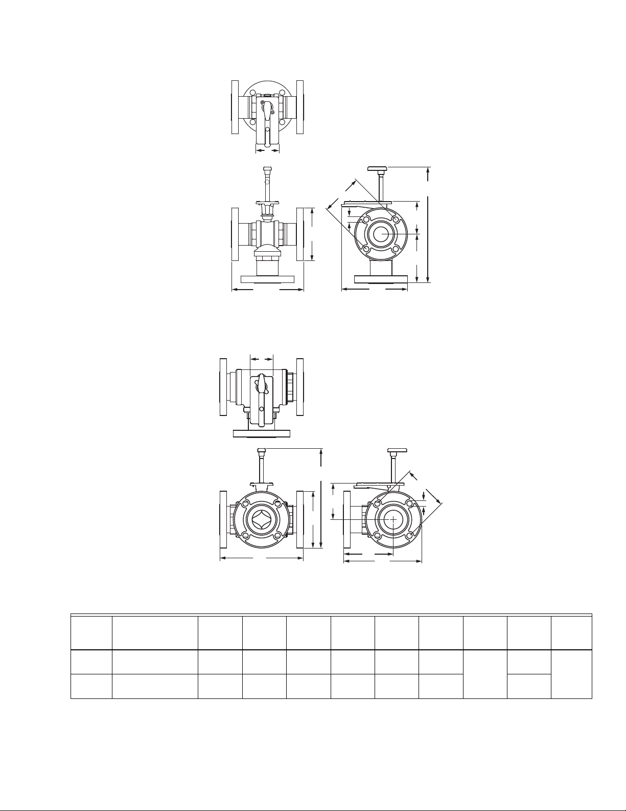
Fig. 4. 2-way 4", 5" & 6" valve dimensions
Table 5. 2-way 4", 5" & 6" valve dimensions
Size
in. Model Number
A
in. (mm)Bin. (mm)
C
in. (mm)
D
in. (mm)
4 VBF5011A1858/U 13 (330) 9 (229) 18-1/8 (460) 14-5/8
(371)
5 VBF5011A1882/U 15 (381) 10 (254) 18-13/16
(478)
6 VBF5011A1916/U 16-1/2
(419)
11 (279) 19-11/16
(500)
15-5/8
(397)
16 3/8 (416) 10-1/8
E
in. (mm)
F
in. (mm)
9-3/8 (238) 4-1/2 (114)
9-11/16
(246)
(257)
Fig. 5. 3-way 4", 5" & 6" valve dimensions
62-2035—02 4
Page 5
VBF5011, VBF5013 CONTROL BALL VALVES WITH FLANGED CONNECTIONS
WARNING
CAUTION
Table 6. 3-way 4", 5" & 6" valve dimensions
B
Size
in. Model NumberAin. (mm)
4 VBF5013B1029/U 13 (330) 9 (229) 1- 13/16
5 VBF5013B1037/U 15 (381) 10
6 VBF5013B1045/U 16-1/2
(419)
in.
(mm)Cin. (mm)Din. (mm)Ein. (mm)
(478)
19-11/16
(254)
11
(279)
(500)
20-3/4
(527)
14-5/8
(371)
15-5/8
(397)
16-3/8
(416)
9-11/16
(246)
10-1/16
(256)
10-11/16
(271)
F
in. (mm)Gin. (mm)Hin. (mm)
8-11/16
(221)
9-5/8 (244) 14-5/8
10-11/16
(271)
1- 3/16
(335)
(371)
16-3/16
(411)
4-1/2
(114)
Valve Installation Location
Select a location where the valve and actuator will be
accessible once installed. Allow sufficient space for
servicing the valve and actuator. Clearance for valve
installation is dependent on actuator size and the valve
pipe size. See Figures 1 and 5 for valve body dimensions.
Refer to actuator literature for actuator dimensions.
1. Clean the lines upstream of the valve to remove par-
ticles larger than 1/16 inch diameter (welding slag,
pipe scale and other contaminants). Upstream
installation of a 20 mesh strainer is recommended.
2. Air should be eliminated from the system so the
valves remain full of fluid during operation.
3. Straight sections of piping upstream and down-
stream of the valves are not necessary for proper
operation. Reducing bushings or flanges may be
attached directly to valves. Standard adapters are
adequate for installation of flow control valves.
4. Proceed with installation once the system specifics
(expansion/contraction of the system and its
medium as well as operating pressures) are within
tolerances.
5. Do not lift the valve by holding the stem.
Severe Burn Hazard.
Contact with hot liquid can lead to severe injury
or cause death. Release system pressure and
isolate or drain the valve pipe section so the
medium (water or glycol solution) does not leak
out of the valve body during installation (see
Fig. 7).
Mounting Valve
1. Before installing the valve, rotate the valve stem to
make sure that the valve stem operates freely.
Impaired stem operation can indicate that the stem
was bent by rough handling. This condition can
require replacing the valve.
2. Protect the stem from damage due to bending or
scratching.
3. For horizontal piping, install the valve so the actua-
tor is above the valve body. Install the valve in any
position between vertical and horizontal. Do not
install the valve with the stem below horizontal or
upside down. For vertical piping, the actuator can be
mounted in any orientation.
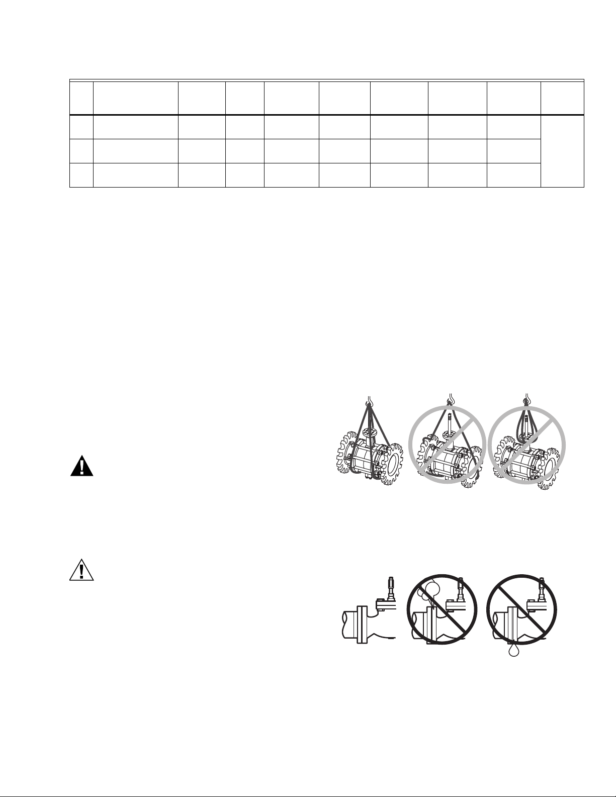
4. Hoist valve by its body only. Do not lift by stem, bon-
net, flanges, or flange holes. (See Fig. 6 for proper
hoisting method.)
M13752
Fig. 6. Proper hoisting of VBF Valves
5. Mount the valve between aligned pipes. Mounting
the valve on pipes that are not aligned causes leakage at the valve-to-pipe connection.
Electrical Shock or Equipment Damage Hazard.
Can shock individuals or short equipment
circuitry.
Disconnect power supply to the actuator to prevent
electrical shock and equipment damage, or remove
and cap the air line to the actuator.
M22591
Fig. 7. Piping must prevent leakage
5 62-2035—02
Page 6

VBF5011, VBF5013 CONTROL BALL VALVES WITH FLANGED CONNECTIONS
M22592
133 IN-LB
(15 NM)
M13753
PORT
CLOSED
PORT
CLOSED
STEM ROTATION
COIL FLOW
STEM ROTATION
BYPASS FLOW
AB
B
A
M23853
Fig. 8. Basic pipe orientation
6. Iron valves are mechanically compatible with stan-
dard ANSI 150 lb flat-faced or raised-face steel
flanges, or with 125 lb cast iron flanges.
7. Release system pressure and drain the valve pipe
section so the medium (water or glycol solution)
does not leak out of the valve body during installation.
8. Mount three-way valves as shown in Fig. 13, accord-
ing to whether they are to be used for mixing or
diverting control.
9. Use a gasket material recommended for the medium
to be handled.
10. Use mounting bolts long enough so the nuts can use
the full length of the nut threads. Use four bolts to
connect 2-1/2" & 3" valves and use eight bolts to
connect 4", 5", & 6" valves. Use bolts 1/8" smaller
than the diameter of the bolt hole to allow clearance
for installing.
MIXED
DISCHARGE
WATER TO
HEAT LOAD
Fig. 9. Basic proper bolt length
VBF5013
B
AB
A
BYPASS
BOILER
PUMP
M34677
Fig. 10. Boiler bypass for reset control
Fig. 11. Stem Rotation
62-2035—02 6
Page 7

VBF5011, VBF5013 CONTROL BALL VALVES WITH FLANGED CONNECTIONS
AB A
B
M34668
HEATING COIL
FULL
H EAT
5 GPM
5 GPM
2.5 GPM
5 GPM
AB A
B
P ROPORTIONED
H EAT
2.5 GPM
S UPPLY
M AIN
RETURN
MAIN
5 GPM
5 GPM
AB
VBF5013
VBF5013
VBF5013
A
B
N O
H EAT
NO FLOW
THROUGH COIL
Stem rotation:
1. For two-way valves:
a. Rotate stem clockwise to open.
b. Rotate stem counter clockwise to close.
2. For three-way valves:
a. Rotate stem clockwise to increase A to AB flow.
b. Rotate stem counter clockwise to increase B to
AB flow.
M13741
Fig. 12. Three-way mixing valve operation with
coil bypass
B PORT
COIL
RETURN
AB PORT A PORT
B PORT
SUPPLY
MIXINGDIVERTING
COIL
M13737
AB PORT A PORT
SUPPLY
RETURN
Fig. 13. Three-way control ball valve flow orientation
(not to scale)
Fig. 14. Vertical Valve Installation
45°
45°
M13740
Fig. 15. Acceptable valve angle from vertical
(when installed in horizontal piping)
7 62-2035—02
Page 8

VBF5011, VBF5013 CONTROL BALL VALVES WITH FLANGED CONNECTIONS
Mounting Actuator
For information on mounting, refer to the Product Data
Sheet for the specific Honeywell actuator coupled to the
valve. It is important to have the correct actuator available
for the installation.
Checkout
For instructions for operating the valve actuator, see the
specific actuator's Product Data Sheet. Operate the
control system and check valve operation to determine
that the valve stem positions the ball smoothly through its
full stroke without binding.Check valve body and
connections for leaks. After installing linkage and
actuator, check the operation according to installation
information provided with these controls. Operate the
system through one complete cycle to be sure the valve
controls properly.
Ensure that the actuator selected provides the force to
position the valve ball. For actuators, the actuator provides
normally closed or normally open operation on electric
power or pressure failure, depending on the
valve/actuator combination selected.
General
Spring return actuators return the valve to its normal
position (open or closed, depending on the actuator and
valve selected) in the event of a power failure. Non-spring
return actuators hold the last commanded position.
HANDLE (REMOVABLE) FOR
MANUALLY ROTATING SHAFT
SCREWS (2)
STEM ASSEMBLY COVER
STEM ASSEMBLY
SCREWS (2)
BOLT
ANTI-ROTATION
BRACKET
MOUNTING
PLATE
WING NUT
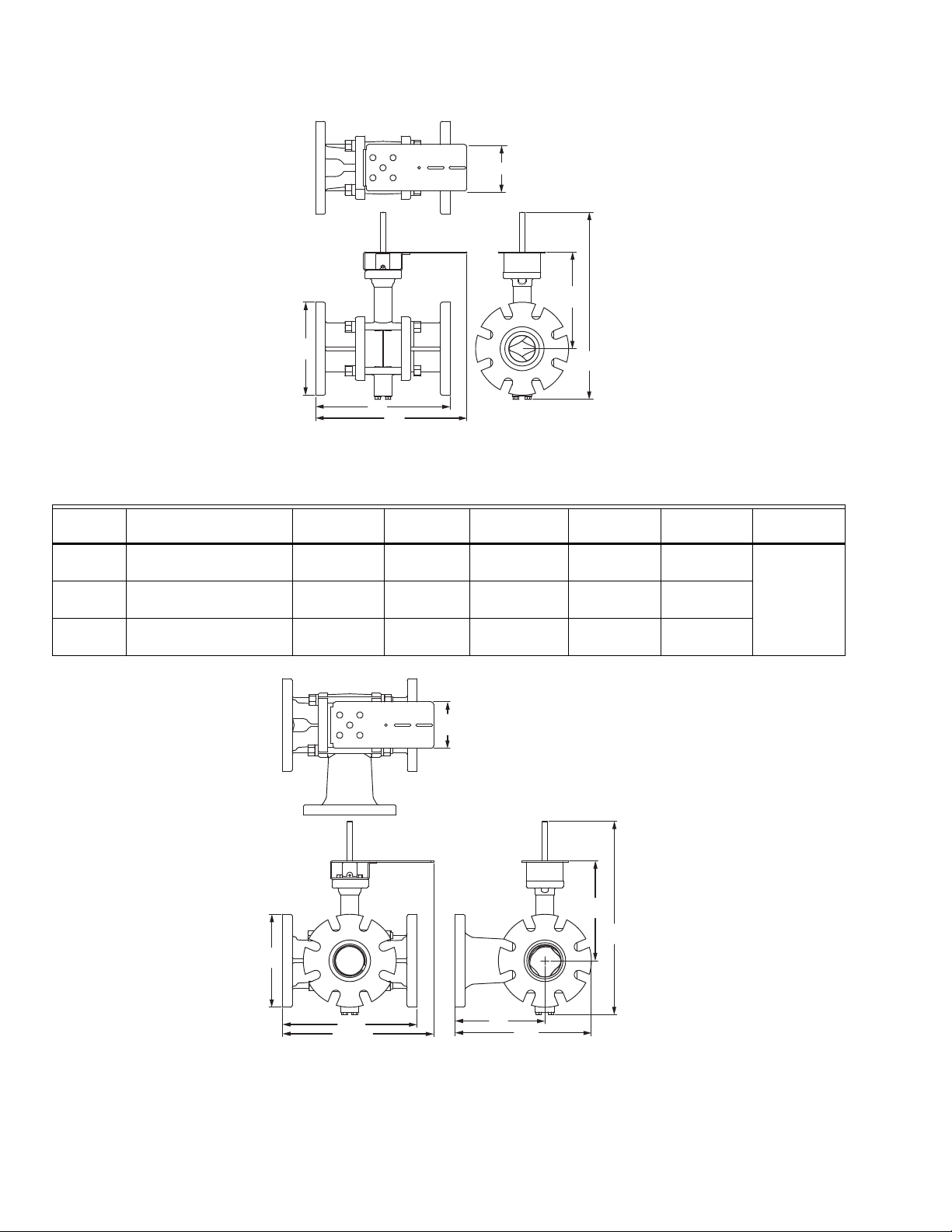
Service Parts
For 2-1/2" & 3", see Fig. 16 for exploded view.
For 4", 5”, & 6", see Table 7 and Fig. 17 for diagram of
replacement parts.
VALVE STEM COUPLER
VALVE BODY
M13738B
Fig. 16. Valve assembly, exploded view
Table 7. Parts list for Flanged Valves
Two-way 4 in. 5 in. 6 in.
Seal 7981-910 7981-915 7981-912
Seal O-ring 7981-914 7981-911 7981-916
Flange O-
7978-65 7978-66 7978-68
ring
Bottom Stem 7981-701 7981-701 7981-701
Three-way 4 in. 5 in. 6 in.
Seal 7981-911 7981-912 7981-913
Seal O-ring 7981-915 7981-916 7981-917
Flange O-
7978-66 7978-67 7978-69
ring
Bottom Stem 7981-701 7981-701 7981-701
62-2035—02 8
Page 9

VBF5011, VBF5013 CONTROL BALL VALVES WITH FLANGED CONNECTIONS
SEAL O-RING
SEAL
STEM
FLANGE O-RING
M13742
.
Fig. 17. Exploded View of Flanged Ball Valve
Mounting Plate Adjustment
The Actuator Mounting Plate can be rotated to a different
position for installation in confined spaces. This is
accomplished as follows:
For 2-1/2" and 3":
1. Remove the handle from the shaft and set it aside.
2. Remove the two screws that hold the stem assembly
to the mounting plate and set them aside.
3. Remove and set aside the stem assembly.
4. Remove and set aside the two screws that attach the
mounting plate to the valve.
5. Remove and set aside hold-down ring from mount-
ing plate.
6. Rotate mounting plate around valve top to the
desired position.
NOTE: Take note of the screw hole positions on the valve.
They limit the mounting plate positions.
7. Lower ring down to valve body and engage it in the
new position relative to the mounting plate.
8. Tighten screws to valve body securing the mounting
plate.
9. Reattach the stem assembly to the mounting plate.
10. If desired, replace the handle on the shaft.
NOTE: See Fig. 16 for valve exploded view.
For 4", 5", and 6":
1. Remove the four bolts and lock washers that hold
the mounting plate to the valve stem housing and
set them aside.
2. Rotate mounting plate around valve top to the
desired position.
NOTE: There are four positions possible (incre-
ments of 90 degrees from each other) for
the mounting plate position
3. Once the mounting plate is in the desired position,
re-insert the bolts through the lock washers and into
the four bolt holes in the valve stem housing.
4. Tighten bolts to the valve body securing the mount-
ing plate.
See Fig. 18 for location of mounting bolts.
9 62-2035—02
Page 10

VBF5011, VBF5013 CONTROL BALL VALVES WITH FLANGED CONNECTIONS
M13745
VALVE STEM
HOUSING
BOLTS WITH
LOCK WASHERS (4)
MOUNTING
PLATE
DRIVE SHAFT
The following wiring instructions are provided as a
convenience to the installing contractor. For more detailed
information about these actuators, refer to the Product
Data sheets for the corresponding Honeywell actuator as
follows:
Literature #Actuator Model and Literature Type
63-2632 MN6105, MN6110, MN7505, MN7510 Floating Actuator (Product Data)
63-2588 MN6120, MN6134 (Product Data)
63-2587 MN7220, MN7234 (Product Data)
63-2607 MS7510, MS7520, MS8110, MS8120 (Product Data)
63-2633 MN6105, MN7505 Modulating Actuator
(Product Data)
The 2-1/2" and 3" valves will be shipped with 2 antirotation clips. Please use narrow clip for MN6105 and
MN7505 actuators and use wide clip for MS8105 and
MS7505.
The 4" and 5" valves will be shipped with 2 sets of antirotation components. Please use short bolt for MN6110
and MN7510 actuators and use long bolt for MS8110 and
MS7510.
The 6" valves will be shipped with 2 sets of anti-rotation
components. Please use short bolt for MN6134 and
MN7234 actuators and use long bolt for MS8120 and
MS7520.
Fig. 18. Mounting Plate Adjustment Bolts
Electrical Installation
Pipe Size
2-1/2” & 3” 4” & 5” 6”
MN6105A1011 MN6110A1003 MN6134A1003
MN7505A2001 MN7510A2001 MN7234A2008
MS8105A1030 MS8110A1008 MS8120A1007
MS7505A2030 MS7510A2008 MS7520A2007*
* 2-position only
1. If necessary, remove actuator wiring cover.
2. Wire actuator using Figures 28 through 37 for the
application required.
3. Replace cover.
Wiring
VALVES WITH NON-SPRING RETURN ACTUATORS
(MN6105, MN7505)
FLOATING ACTUATOR
Direct
Service/Off
Reverse
432
1
24 VAC
POWER SUPPLY. PROVIDE DISCONNECT MEANS
1
AND OVERLOAD PROTECTION AS REQUIRED.
CONNECTION REQUIRED FOR SPST CONTROL.
2
Fig. 19. Wiring for On/Off Control
CONTROLLER
2
M18945A
62-2035—02 10
Page 11

VBF5011, VBF5013 CONTROL BALL VALVES WITH FLANGED CONNECTIONS
ACTUATOR
SPST
24 VAC
1
1
2
2
LINE VOLTAGE POWER SUPPLY.
PROVIDE DISCONNECT MEANS AND
OVERLOAD PROTECTION AS REQUIRED.
24 VDC SUPPLY ACCEPTABLE.
V
1
2
M19718B
24 VAC
1
1
2
3
2
LINE VOLTAGE POWER SUPPLY.
PROVIDE DISCONNECT MEANS AND
OVERLOAD PROTECTION AS REQUIRED.
24 VDC SUPPLY ACCEPTABLE.
SET SWITCH TO FLOATING.
M19573A
ACTUATOR
V
OR +
OR N/A
FEEDBACK
5
4
3
1
2
2-10 VDC
10-2 VDC
0-10 VDC
10-0 VDC
Fltg, fwd
Fltg, rev
3
FLOATING ACTUATOR
Direct
Service/Off
Reverse
2
1
24 VAC
1
POWER SUPPLY. PROVIDE DISCONNECT MEANS
AND OVERLOAD PROTECTION AS REQUIRED.
4
3
Fig. 20. Wiring for Floating Control
2 -10 Vdc
PROPORTIONAL ACTUATOR
0 -10 Vdc
0 -10 Vdc
2 -10 Vdc
FLOATING
CONTROLLER
M18946A
VALVES WITH SPRING RETURN ACTUATORS (MS7505,
MS8105)
1
1 LINE VOLTAGE POWER SUPPLY.
PROVIDE DISCONNECT MEANS AND
OVERLOAD PROTECTION AS REQUIRED.
SPST
1
2
ACTUATOR
V
M22289
Fig. 22. Wiring for On/Off Control
1
1
POWER SUPPLY. PROVIDE DISCONNECT MEANS
AND OVERLOAD PROTECTION AS REQUIRED.
2
0(2)-10 VDC OF 0(4)-20 mA CONTROL SIGNAL ACCEPTABLE.
SET CONTROL SIGNAL DIP SWITCH TO "OFF" FOR VOLTAGE.
SET TO "ON" FOR CURRENT.
+
FEEDBACK
1 32 5
PROPORTIONAL
24 VAC
Fig. 21. Wiring for Modulating Control
CONTROLLER
FEEDBACK
+
-
M18947A
2
Fig. 23. Wiring for Floating Control
(Floating mode setting)
11 62-2035—02
Page 12

VBF5011, VBF5013 CONTROL BALL VALVES WITH FLANGED CONNECTIONS
ACTUATOR
0/2 TO 10 VDC
PROPORTIONING
CONTROLLER
24 VAC
1
1
2
3
2
LINE VOLTAGE POWER SUPPLY.
PROVIDE DISCONNECT MEANS AND
OVERLOAD PROTECTION AS REQUIRED.
24 VDC SUPPLY ACCEPTABLE.
SET SWITCH TO MODULATING.
V
OR +
OR N/A
FEEDBACK
–
+
FEEDBACK
5
4
3
1
2
M19576A
2-10 VDC
10-2 VDC
0-10 VDC
10-0 VDC
Fltg, fwd
Fltg, rev
3
SPDT
ACTUATOR
0/2 TO 10 VDC
PROPORTIONING
CONTROLLER
24 VAC
1
1
2
3
2
LINE VOLTAGE POWER SUPPLY.
PROVIDE DISCONNECT MEANS AND
OVERLOAD PROTECTION AS REQUIRED.
24 VDC SUPPLY ACCEPTABLE.
SET SWITCH TO MODULATING.
V
OR +
OR N/A
FEEDBACK
–
+
FEEDBACK
5
4
3
1
2
M19577A
2-10 VDC
10-2 VDC
0-10 VDC
10-0 VDC
Fltg, fwd
Fltg, rev
3
SPST
1
0/2 TO 10 VDC
PROPORTIONING
CONTROLLER
–
+
FEEDBACK
LINE VOLTAGE POWER SUPPLY.
1
PROVIDE DISCONNECT MEANS AND
OVERLOAD PROTECTION AS REQUIRED.
2
24 VDC SUPPLY ACCEPTABLE.
3
SET SWITCH TO MODULATING.
Fig. 24. Override to full open
1
(Modulating mode setting)
4 TO 20 mA
PROPORTIONING
CONTROLLER
–
+
FEEDBACK
LINE VOLTAGE POWER SUPPLY.
1
PROVIDE DISCONNECT MEANS AND
OVERLOAD PROTECTION AS REQUIRED.
2
24 VDC SUPPLY ACCEPTABLE.
3
SET SWITCH TO MODULATING.
24 VAC
24 VAC
2
2
490 TO 510
OHMS,
1/2 W
MINIMUM
1
2
3
4
5
3
1
2
3
4
5
3
ACTUATOR
V
OR +
OR N/A
FEEDBACK
2-10 VDC
10-2 VDC
0-10 VDC
10-0 VDC
Fltg, fwd
Fltg, rev
M19574A
ACTUATOR
V
OR +
OR N/A
FEEDBACK
2-10 VDC
10-2 VDC
0-10 VDC
10-0 VDC
Fltg, fwd
Fltg, rev
M22282A
Fig. 25. Override to full closed
(Modulating mode setting)
62-2035—02 12
Fig. 26. Wiring for Proportioning Controllers
(Modulating mode setting)
Page 13

VBF5011, VBF5013 CONTROL BALL VALVES WITH FLANGED CONNECTIONS
ACTUATOR
0/2 TO 10 VDC
PROPORTIONING
CONTROLLER
1
2
3
2
LINE VOLTAGE POWER SUPPLY.
PROVIDE DISCONNECT MEANS AND
OVERLOAD PROTECTION AS REQUIRED.
24 VDC SUPPLY ACCEPTABLE.
SET SWITCH TO MODULATING.
V
OR +
OR N/A
FEEDBACK
5
4
3
1
2
M22288
2-10 VDC
10-2 VDC
0-10 VDC
10-0 VDC
Fltg, fwd
Fltg, rev
3
ACTUATOR
V
OR +
OR N/A
FEEDBACK
5
4
3
1
2
2-10 VDC
10-2 VDC
0-10 VDC
10-0 VDC
Fltg, fwd
Fltg, rev
3
24 VAC
1
24 VAC
1
2
24 VAC
1
HOT
COM
–
+
432
FLOATING ACTUATOR
24 VAC
1
1
POWER SUPPLY. PROVIDE DISCONNECT MEANS
AND OVERLOAD PROTECTION AS REQUIRED.
CONNECTION REQUIRED FOR SPST CONTROL.
2
CONTROLLER
2
Direct
Reverse
Service/Off
M18945A
4
3
2
FLOATING ACTUATOR
24 VAC
Direct
Reverse
Service/Off
1
1
POWER SUPPLY. PROVIDE DISCONNECT MEANS
AND OVERLOAD PROTECTION AS REQUIRED.
FLOATING
CONTROLLER
M18946A
.
Fig. 29. Wiring for Floating Control
Fig. 27. Wiring for Proportioning controllers operating
multiple actuators (Modulating mode setting)
VALVES WITH NON-SPRING RETURN ACTUATORS
(MN6110A, MN6134A, MN7234A, MN7510A)
Fig. 28. Wiring for On/Off Control
2 -10 Vdc
PROPORTIONAL ACTUATOR
0 -10 Vdc
0 -10 Vdc
2 -10 Vdc
+
FEEDBACK
1 32 5
1
24 VAC
1
POWER SUPPLY. PROVIDE DISCONNECT MEANS
AND OVERLOAD PROTECTION AS REQUIRED.
2
0(2)-10 VDC OF 0(4)-20 mA CONTROL SIGNAL ACCEPTABLE.
SET CONTROL SIGNAL DIP SWITCH TO "OFF" FOR VOLTAGE.
SET TO "ON" FOR CURRENT.
Fig. 30. Wiring for Modulating Control
13 62-2035—02
PROPORTIONAL
CONTROLLER
FEEDBACK
+
2
-
M18947A
Page 14

VBF5011, VBF5013 CONTROL BALL VALVES WITH FLANGED CONNECTIONS
24 VAC
1
1
2
3
2
LINE VOLTAGE POWER SUPPLY.
PROVIDE DISCONNECT MEANS AND
OVERLOAD PROTECTION AS REQUIRED.
24 VDC SUPPLY ACCEPTABLE.
SET SWITCH TO FLOATING.
M19573A
ACTUATOR
V
OR +
OR N/A
FEEDBACK
5
4
3
1
2
2-10 VDC
10-2 VDC
0-10 VDC
10-0 VDC
Fltg, fwd
Fltg, rev
3
ACTUATOR
0/2 TO 10 VDC
PROPORTIONING
CONTROLLER
24 VAC
1
1
2
3
2
LINE VOLTAGE POWER SUPPLY.
PROVIDE DISCONNECT MEANS AND
OVERLOAD PROTECTION AS REQUIRED.
24 VDC SUPPLY ACCEPTABLE.
SET SWITCH TO MODULATING.
V
OR +
OR N/A
FEEDBACK
–
+
FEEDBACK
5
4
3
1
2
M19576A
2-10 VDC
10-2 VDC
0-10 VDC
10-0 VDC
Fltg, fwd
Fltg, rev
3
SPDT
ACTUATOR
0/2 TO 10 VDC
PROPORTIONING
CONTROLLER
24 VAC
1
1
2
3
2
LINE VOLTAGE POWER SUPPLY.
PROVIDE DISCONNECT MEANS AND
OVERLOAD PROTECTION AS REQUIRED.
24 VDC SUPPLY ACCEPTABLE.
SET SWITCH TO MODULATING.
V
OR +
OR N/A
FEEDBACK
–
+
FEEDBACK
5
4
3
1
2
M19574A
2-10 VDC
10-2 VDC
0-10 VDC
10-0 VDC
Fltg, fwd
Fltg, rev
3
VALVES WITH SPRING RETURN ACTUATORS
(MS7510A, MS7520A, MS8110A, MS8120A)
1
1
2
24 VAC
2
LINE VOLTAGE POWER SUPPLY.
PROVIDE DISCONNECT MEANS AND
OVERLOAD PROTECTION AS REQUIRED.
24 VDC SUPPLY ACCEPTABLE.
SPST
Fig. 31. Wiring for On/Off Control
Fig. 32. Wiring for Floating Control
(Floating mode setting)
1
2
ACTUATOR
V
M19718B
Fig. 34. Wiring for Proportioning Controllers
(Modulating mode setting)
ACTUATOR
1
4 TO 20 mA
PROPORTIONING
CONTROLLER
FEEDBACK
1
2
3
24 VAC
2
500
OHMS
–
+
LINE VOLTAGE POWER SUPPLY.
PROVIDE DISCONNECT MEANS AND
OVERLOAD PROTECTION AS REQUIRED.
24 VDC SUPPLY ACCEPTABLE.
SET SWITCH TO MODULATING.
1
2
3
4
5
3
FEEDBACK
V
OR +
OR N/A
2-10 VDC
10-2 VDC
0-10 VDC
10-0 VDC
Fltg, fwd
Fltg, rev
M22282
Fig. 33. Override to full open
(Modulating mode setting)
62-2035—02 14
Fig. 35. Wiring for Proportioning Controllers
(Modulating mode setting)
Page 15

Fig. 36. Override to full closed
ACTUATOR
0/2 TO 10 VDC
PROPORTIONING
CONTROLLER
24 VAC
1
1
2
3
2
LINE VOLTAGE POWER SUPPLY.
PROVIDE DISCONNECT MEANS AND
OVERLOAD PROTECTION AS REQUIRED.
24 VDC SUPPLY ACCEPTABLE.
SET SWITCH TO MODULATING.
V
OR +
OR N/A
FEEDBACK
–
+
FEEDBACK
5
4
3
1
2
M19577A
2-10 VDC
10-2 VDC
0-10 VDC
10-0 VDC
Fltg, fwd
Fltg, rev
3
SPST
ACTUATOR
0/2 TO 10 VDC
PROPORTIONING
CONTROLLER
1
2
3
2
LINE VOLTAGE POWER SUPPLY.
PROVIDE DISCONNECT MEANS AND
OVERLOAD PROTECTION AS REQUIRED.
24 VDC SUPPLY ACCEPTABLE.
SET SWITCH TO MODULATING.
V
OR +
OR N/A
FEEDBACK
5
4
3
1
2
M22288
2-10 VDC
10-2 VDC
0-10 VDC
10-0 VDC
Fltg, fwd
Fltg, rev
3
ACTUATOR
V
OR +
OR N/A
FEEDBACK
5
4
3
1
2
2-10 VDC
10-2 VDC
0-10 VDC
10-0 VDC
Fltg, fwd
Fltg, rev
3
24 VAC
1
24 VAC
1
2
24 VAC
1
HOT
COM
–
+
(Modulating mode setting)
VBF5011, VBF5013 CONTROL BALL VALVES WITH FLANGED CONNECTIONS
Fig. 37. Wiring for Proportioning controllers operating
multiple actuators (Modulating mode setting)
15 62-2035—02
Page 16

VBF5011, VBF5013 CONTROL BALL VALVES WITH FLANGED CONNECTIONS
OPERATION AND CHECKOUT
Once both the mechanical and electrical installations are
complete:
1. Cycle the actuator to verify that the direction of rota-
tion suits the control sequence.
2. If the rotation direction is incorrect:
a. For 2-position control actuators: Remount
actuator on the bracket.
b. For floating control actuators: Reverse two
control signal wires (CW/CCW).
c. For analog control actuators either:
(1) Reposition reverse/direct acting switch, or
3. If the control scheme requires fail-safe operation,
4. If the fail safe position is incorrect, remove and rein-
(2) Remount actuator on the bracket.
ensure that, upon removal of power, the fail position
coincides with the control sequence.
stall the actuator in the opposite orientation as follows:
a. Loosen the shaft coupling bolt using a 10 mm
wrench.
b. Loosen all other mounting bolts connecting the
actuator to the mounting bracket and set aside.
c. Remove the actuator from the valve shaft.
d. Move the actuator coupling to the opposite side
of the actuator, as displayed in Figure 38.
Fig. 38. Mounting shaft coupling to actuator
(1) Remove the retainer clip from the shaft cou-
pling and set it aside for later use.
(2) Remove shaft coupling from one side of the
actuator.
(3) Replace the shaft coupling on the opposite
side of the actuator, aligning it based on the
stroke labeling.
(4) Replace the retainer clip on the shaft cou-
pling using the groove of the coupling.
e. Reconnect the actuator to the valve mounting
bracket by replacing the screws previously
removed (step b)
f. Tighten the shaft coupling bolt using a 10 mm
wrench.
M19579A
opposite side
Honeywell Building Technologies
In the U.S.:
Honeywell
buildingcontrols.honeywell.com
® U.S. Registered Trademark
©2020 Honeywell International Inc.
62-2035—02 M.S. Rev. 10-20
Printed in United States
 Loading...