

Page 1
62-3117-02
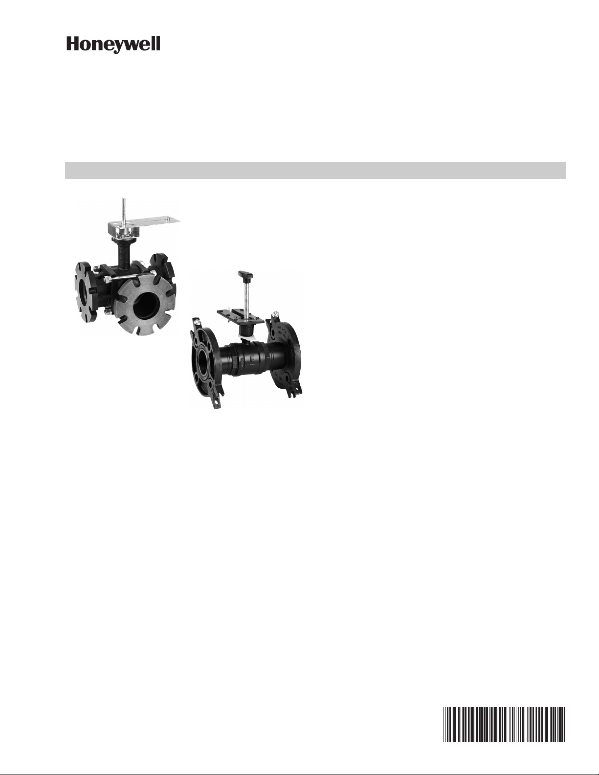
VBF5011, VBF5013 Control Ball
4", 5" and 6"
2-1/2" and 3"
Valves With Flanged Connections
SPECIFICATION DATA
FEATURES
All Models
• Sizes from 2-1/2" to 6" with ANSI Class 125 flanged
connections.
• Flow characteristics.
• Two-way: equal percentage
• Three-way: A-AB equal percentage, B-AB linear
• Can be used with Honeywell electronic actutors.
• Field configurable for normally open or normally
closed fail-safe position.
• For 2-1/2 and 3", removable manual operating
handle to control valve during installation or in an
event of power failure.
• ANSI Class IV leakage specification (0.01% of CV).
• 2-way - ANSI Class IV leakage
• 3-way - A to AB; ANSI Class IV leakage
• 3-way - B to AB; ANSI Class III leakage
• Option of four actuator mounting positions on the
valve for 4", 5" and 6" valves.
APPLICATION
The VBF5011 Two-Way and the VBF5013 Three-Way
Control Ball Valve control hot and chilled water with glycol
solutions up to 50% in heating, ventilating and air
conditioning (HVAC) systems to provide two-position or
modulating functions.
• Wide range of C
• Valve ball and stem 316 stainless steel for all valves
except 3-way 2-1/2" valve.
VBF5013 (Three-way)
• Mixing or diverting control.
• Same flow pattern configuration as Globe valve.
choices from 63 to 360.
V
These valve can be used with Honeywell electronic
actuators.
Page 2
VBF5011, VBF5013 CONTROL BALL VALVES WITH FLANGED CONNECTIONS
SPECIFICATIONS
Table 1. Model Selection
Valve Fitting Body / Flow
VB = valve, ball
F = Flanged
5011 = 2-way
5013 = 3 way
Table 2. Control Ball Valve Part Numbers
Part# Description
VBF5011A1734/U 2-1/2", 2-WAY CONTROL BALL
VALVE, 63 CV
VBF5011A1767/U 3", 2-WAY CONTROL BALL VALVE,
100 CV
VBF5011A1858/U 4", 2-WAY CONTROL BALL VALVE,
160 CV
VBF5011A1882/U 5", 2-WAY CONTROL BALL VALVE,
250 CV
VBF5011A1916/U 6", 2-WAY CONTROL BALL VALVE,
360 CV
VBF5013B1003/U 2 1/2", 3-WAY CONTROL BALL
VALVE, 63 CV
VBF5013B1011/U 3", 3-WAY CONTROL BALL VALVE,
100 CV
VBF5013B1029/U 4", 3-WAY CONTROL BALL VALVE,
160 CV
VBF5013B1037/U 5", 3-WAY CONTROL BALL VALVE,
250 CV
VBF5013B1045/U 6", 3-WAY CONTROL BALL VALVE,
360 CV
Dimensions: Refer to Figures 1 through 5 and Tables 6
through 9.
Body Style: Two-way control ball valve, straight-through
flow, full or reduced port using laser-milled stainless
steel control ball.
Three-way control ball valve, A-B-AB characterized flow,
laser-milled stainless steel control ball.
Combination ANSI 125/PN16 flanged connections.
Body Size: 2-1/2" to 6" (DN65, DN80, DN100, DN125,
DN150).
Torque Requirement: See Table 4.
Body Pressure Rating (maximum):
For 2-1/2" & 3":
360 psi (2482 kPa) at 250° F (121° C).
For 4:, 5", & 6":
240 psi (1655 kPa) at 250° F (121° C).
Controlled Medium: Water or Glycol solutions up to 50%.
Not suitable for combustible gases.
Fluid Temperature Range: -22 to +250° F (-30 to +121°
C).
Flow Characteristics:
Two-way: Equal Percentage.
Three-way: Port A to AB: Equal Percentage.
Port B to AB: Linear with 20% reduced flow
capacity.
Rangeability:
Rangeability is a measure of a valve's controllability
(sometimes referred to as its Turndown Ratio). Rangeabil-
ity is
a measured property and is expressed as the ratio of a
valve's
maximum flow rate to its minimum controllable flow rate.
For 2-1/2": 250
For 3": 558
For 4", 5", & 6": 500:1 minimum.
Mounting: Bolt holes conform to ANSI B16.1.
Materials:
For 2-way 2-1/2", 3" & 3-way 2-1/2":
Body: Forged Brass (ASTM B283)
Flanges: Cast iron ductile ANSI Class 125
Flow Optimizer: Noryl®
Ball and Stem:
Two-way: Stainless Steel
Three-way: Nickel-chrome Plated Brass.
Stem Seals: EPDM O-rings.
Ball Seals: Reinforced TEFLON™ Seals with EPDM Orings.
For 2-way 4", 5", & 6" & 3-way 3", 4", 5", & 6",
Body: Cast Iron ASTM A395, 60-40-18
Ball and Stem: 316 Stainless Steel.
Stem Seals: EPDM O-Rings.
Ball Seals: Teflon
Leakage Rating:
Valves: ANSI Class IV close-off/leakage (A port only).
2-way - ANSI Class IV leakage
3-way - A to AB; ANSI Class IV leakage
3-way - B to AB; ANSI Class III leakage
Accessories:
For 4", 5", and 6", see Table 3 for replacement parts.
Two-way 4 in. 5 in. 6 in.
Seal 7981-910 7981-915 7981-912
Seal O-ring 7981-914 7981-911 7981-916
Flange Oring
Bottom Stem 7981-701 7981-701 7981-701
Three-way 4 in. 5 in. 6 in.
Seal 7981-911 7981-912 7981-913
Seal O-ring 7981-915 7981-916 7981-917
Flange Oring
Bottom Stem 7981-701 7981-701 7981-701
®
Seals with EPDM O-rings
Table 3. Parts list for Flanged Valves
7978-65 7978-66 7978-68
7978-66 7978-67 7978-69
62-3117—02 2
Page 3
VBF5011, VBF5013 CONTROL BALL VALVES WITH FLANGED CONNECTIONS
Application Notes
IMPORTANT
Valve sizing is important for correct system operation. Undersized valves do not have sufficient
capacity at maximum load. Oversized valves do not
have sufficient authority over the load in modulating applications. Oversized valves can cause
excessive cycling and the seat and ball can be
damaged because of the restricted opening.
Proper Use
These valves are only for use in cold, warm and hot water
systems. Not suitable for oil, or combustible gases. For
water application, they are designed for a medium
temperature range from -22 to 250°F, at a maximum
pressure of 360 psi for 2-1/2" & 3" valves and 240 psi for
4", 5", & 6" valves. The valves are to be operated with the
appropriate Honeywell electronic actuators only. Water
should be properly filtered, treated and conditioned
according to local conditions and the recommendations of
the boiler or chiller manufacturers. The installation of a
strainers and filters is recommended.
IMPORTANT
The presence of excessive iron oxide (red rust) in
the system voids the valve warranty.
Required Torque
Honeywell electronic actuators can be utilized with the
VBF5011 and VBF5013 valves. See Table 4, which lists the
torque requirement for each valve size. See Table 5, which
lists the close-off pressure rating for the valves with the
different torque actuators. Larger torque actuators may be
used, but there is no increase in close-off pressure rating.
Table 4. Torque Requirement
Tor que
Requirement
Type Size
2-way 2 1/2” 35
3” 35
4” 85
5” 85
6” * 140
3-way 2 1/2” 35
3” 85
4” 85
5” 85
6” * 140
* 6” requires 140 in-lb actuator for flows up to
700 gpm. For flow rates greater than 700 gpm
a 200 in-lb actuator is recommended.
Table 5. Close-off Pressure Rating
35 lb-in
Valve
Valve
Type
2-way 2-1/2”, 3”100
3-way 2-1/2” 40
3-way 3” 70 70 70 70
2-way,
4” 70 70 70 70
3-way
2-way,
5” 70 70 70 70
3-way
2-way,
6” 70 70
3-way
(4 Nm)
Size
88 lb-in
(10 Nm)
Close-off pressure rating (psi)
(in-lbs)
Actuator Type
175 lb-in
(20 Nm)
2-position
175 lb-in
(20 Nm)
300 lb-in
(34 Nm)
Flow Characteristics
VBF5011 Two-Way Control Ball Valves have:
• an equal percentage flow characteristic.
VBF5013 Three-Way Control Ball Valves have:
• between ports A and AB: an equal percentage flow
characteristic.
• between ports B and AB: a linear flow characteristic
with 20% reduced flow capacity.
3 62-3117—02
Page 4

VBF5011, VBF5013 CONTROL BALL VALVES WITH FLANGED CONNECTIONS
H
C
F
G
B
E
Size
in. Model Number
(mm)
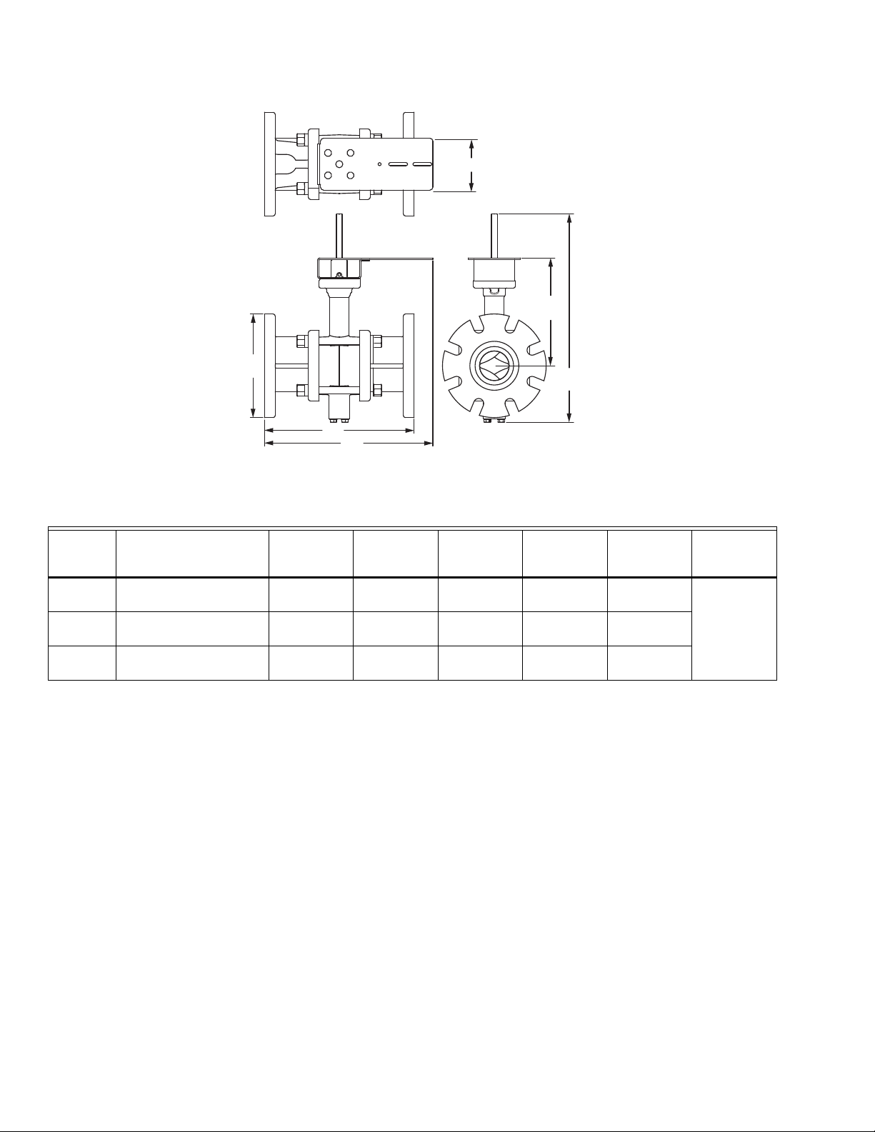
2 1/2 VBF5011A1734/U 9 1/2
(241)
3 VBF5011A1767/U 11
(279)
A
D
M34652
Fig. 1. 2-way 2-1/2" & 3" valve dimensions
Table 6. 2-way 2-1/2" & 3" valve dimensions
A
in.
(mm)
7
(178)
7 1/2
(191)
B
in.
C
in.
(mm)
12 3/8
(314)
12 5/8
(321)
D
in.
(mm)
8 3/4
(222)
9
(229)
E
in.
(mm)
4 5/16
(110)
(mm)
5 1/2
(140)
6
(152)
F
in.
3/4
(19)
G
in.
(mm)
H
in.
(mm)
3
(76)
62-3117—02 4
Page 5

VBF5011, VBF5013 CONTROL BALL VALVES WITH FLANGED CONNECTIONS
M34653
A
C
D
F
I
B
G
E
H
M34656
H
D
C
I
A
B
E
G
F
Fig. 2. 3-way 2-1/2" valve dimensions
Fig. 3. 3-way 3" valve dimensions
Size
in. Model Number
2 1/2 VBF5013B1003/U 9 1/2
(241)
3 VBF5013B1011/U 11
(279)
Table 7. 3-way 2-1/2" & 3" valve dimensions
A
in.
(mm)
in.
(mm)
7
(178)
7 1/2
(191)
B
C
in.
(mm)
15 5/16
(389)
13 1/8
(333)
D
in.
(mm)
8 3/4
(222)
10 5/16
(262)
5 62-3117—02
4 5/16
(110)
4 13/16
(122)6(152)
E
in.
(mm)
in.
(mm)
5 1/2
(140)
F
(mm)
3/4
(19)
G
in.
H
in.
(mm)
6 7/16
(164)
I
in.
(mm)
3
(76)
6 5/8
(168)
Page 6
VBF5011, VBF5013 CONTROL BALL VALVES WITH FLANGED CONNECTIONS
F
E
B
Fig. 4. 2-way 4", 5" & 6" valve dimensions
Table 8. 2-way 4", 5" & 6" valve dimensions
Size
in. Model Number
(mm)
4 VBF5011A1858/U 13
(330)
5 VBF5011A1882/U 15
(381)
6 VBF5011A1916/U 16 1/2
(419)
A
in.
C
A
D
M34654
B
in.
(mm)
9
(229)
10
(254)
11
(279)
C
in.
(mm)
18 1/8
(460)
18 13/16
(478)
19 11/16
(500)
(mm)
14 5/8
(371)
15 5/8
(397)
16 3/8
(416)
D
in.
E
in.
(mm)
9 3/8
(238)
9 11/16
(246)
10 1/8
(257)
F
in.
(mm)
4 1/2
(114)
62-3117—02 6
Page 7

VBF5011, VBF5013 CONTROL BALL VALVES WITH FLANGED CONNECTIONS
F
G
H
M34655
B
A
D
C
E
Size
in. Model Number
in.
(mm)
4 VBF5013B1029/U 13
(330)
5 VBF5013B1037/U 15
(381)
6 VBF5013B1045/U 16 1/2
(419)
A
Fig. 5. 3-way 4", 5" & 6" valve dimensions
Table 9. 3-way 4", 5" & 6" valve dimensions
B
in.
(mm)
9
(229)
10
(254)
11
(279)
C
in.
(mm)
18 13/16
(478)
19 11/16
(500)
20 3/4
(527)
D
in.
(mm)
14 5/8
(371)
15 5/8
(397)
16 3/8
(416)
E
in.
(mm)
9 11/16
(246)
10 1/16
(256)
10 11/16
(271)
F
in.
(mm)
8 11/16
(221)
9 5/8
(244)
10 11/16
(271)
G
in.
(mm)
13 3/16
(335)
14-5/8
(371)
16 3/16
(411)
H
in.
(mm)
4 1/2
(114)
7 62-3117—02
Page 8

VBF5011, VBF5013 CONTROL BALL VALVES WITH FLANGED CONNECTIONS
TYPICAL SPECIFICATIONS
ACCESSORIES
Identification tags shall be available for all valves; tags
shall be indelibly marked with C
location.
, model number and
V
Honeywell
®
is a registered trademark of Honeywell International.
Tef lon® is a registered trademark of E I DuPont de Nemours.
By using this Honeywell literature, you agree that Honeywell will have no liability for any damages arising out of your use or
modification to, the literature. You will defend and indemnify Honeywell, its affiliates and subsidiaries, from and against any
liability, cost, or damages, including attorneys’ fees, arising out of, or resulting from, any modification to the literature by you.
Honeywell Building Technologies
In the U.S.:
Honeywell
715 Peachtree Street NE
Atlanta, GA 30308
customer.honeywell.com
buildingcontrols.honeywell.com
® U.S. Registered Trademark
©2020 Honeywell International Inc.
62-3117—02 M.S. Rev. 10-20
Printed in United States
 Loading...