

Page 1
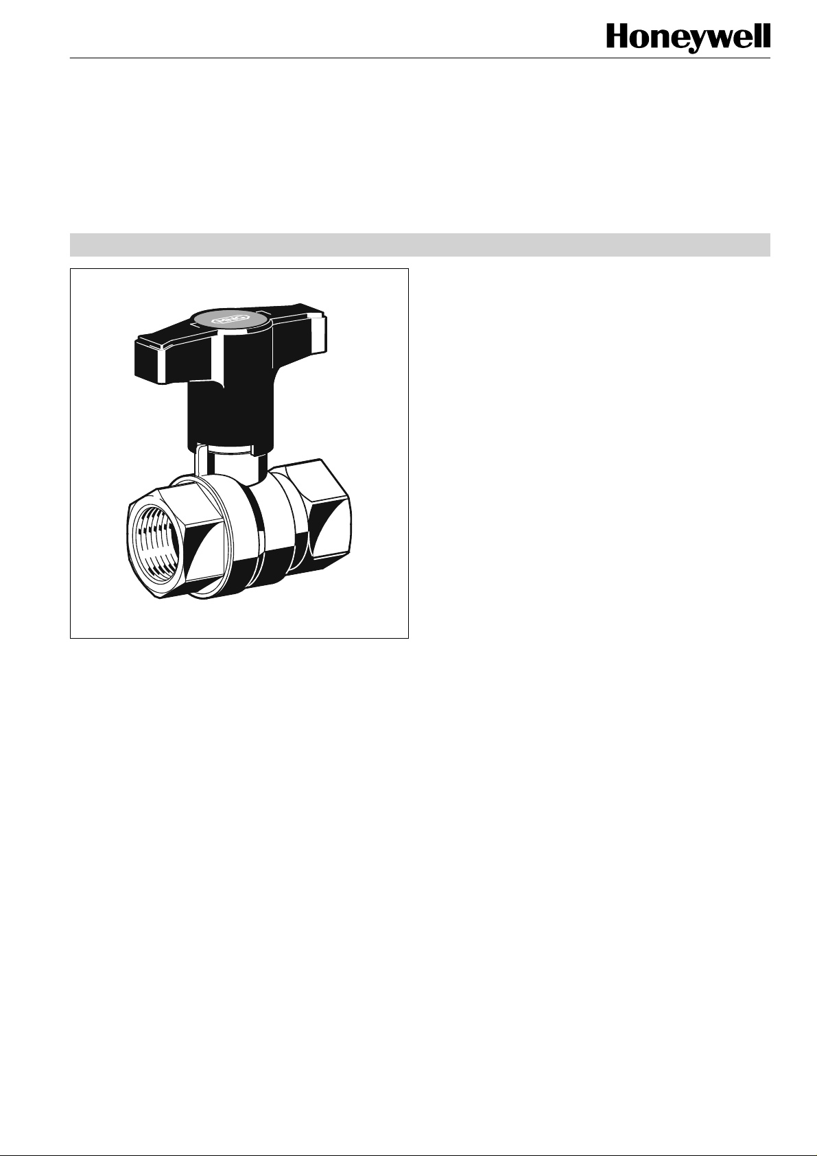
VB550
Stop-Ball
BRASS BALLVALVE
PRODUCT DATA
Application
Stop-Ball ballvalves are used as shutoff valves in hydronic
heating and cooling systems.
The straight body design enables easy operation, even when
installed at places difficult to reach.
Features
• Valve body made of brass
• High flow rates
• Easy operation due to straight body design
• Available from DN15 to DN50
Specifications
Design
The Stop-Ball consists of:
•
Valve housing with internal threads to ISO228/1
•
Ball with sealing
•
Hand lever/spindle assembly
Materials
•
Valve housing made of brass
•
Ball made of hard chrome-plated brass, with sealing rings
made of PTFE
•
Spindle made of brass with sealing ring made of PTFE, O-
ring made of Viton and brass packing
•
Lever for DN15-DN32 made of plastic, for DN40 and DN50
made of rubber-coated steel
Medium
Operating temperature
Operating pressure
vs
(cv)-values
k
Water or water-glycol mixture
2...130°C (36...266°F)
max. 16 bar (232 psi)
DN15 14,8 (17,3)
DN20 36,0 (42,1)
DN25 70,0 (81,9)
DN32 112,0 (131),0
DN40 202,0 (236),0
DN50 288,0 (337),0
Function
Ballvalves have a ball with a bore hole inside the valve housing. When the valve is open the medium flows through this
bore. When the valve is closed by turning the lever by 90° the
ball is turned accordingly. The valve opening is closed as the
bore then lies crosswise to the valve opening. The pipeline is
shutoff.
Copyright © 2002 Honeywell AG • All rights reserved EN0H-0185GE25 R0402
Page 2
STOP-BALL (VB550)
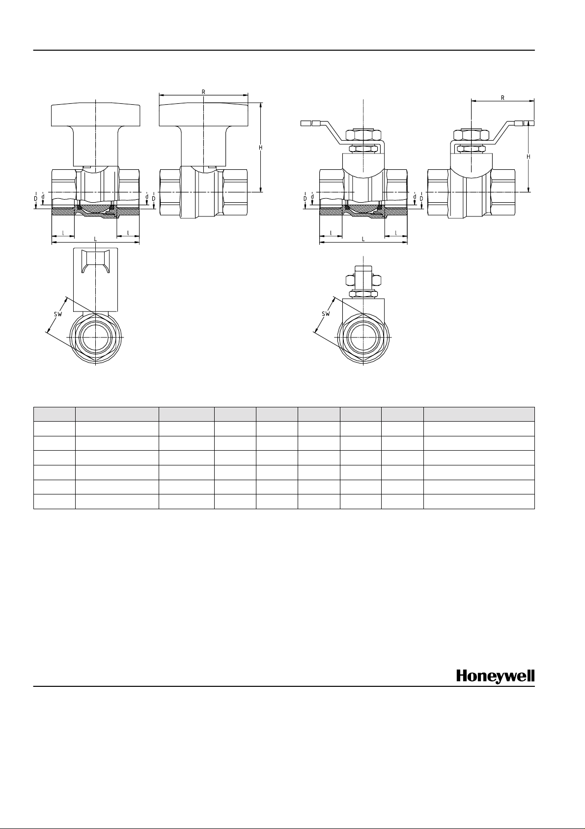
Dimensions and Ordering Information
Fig. 1. Stop-Ball DN15 to DN32 Fig. 2. Stop-Ball DN40 and DN50
Table 1. Dimensions and OS-Nos. (OS=Order System)
DN (=d) kvs (cv)-value D H l L R SW OS-No.
15
20
25
32
40
50
NOTE: All dimensions in mm unless otherwise stated.
14,8 (17,3)
36,0 (42,1)
70,0 (81,9)
112,0 (131),0
202,0 (236),0
288,0 (337),0
G1/2” 69 12,0 49,5 80 27 VB550Y0015
G3/4” 74 13,0 58,0 80 32 VB550Y0020
G1” 80 14,0 68,0 80 41 VB550Y0025
G1 1/4” 85 16,5 81,0 80 50 VB550Y0032
G1 1/2” 82 17,5 93,5 150 55 VB550Y0040
G2” 89 19,0 109,0 150 70 VB550Y0050
Control Products
Honeywell AG Phone: (49) 2932 9880
Zu den Ruhrwiesen 3 Fax: (49) 2932 988239
D-59755 Arnsberg-Neheim mng@honeywell.com http://europe.hbc.honeywell.com
EN0H-0185GE25 R0402 2 Subject to change • All rights reserved
 Loading...