

Honeywell VAM Installation & Setup Manual
Make Wiring Connections
Mount the VAM
Insert an SD/SDHC Memory Card
VAM (VISTA Automation Module) - Installation & Setup Guide
Introduction
VISTA Automation Module (herein referred to as “VAM”) combines home automation and home security and is intended
for use with compatible VISTA
technology allowing VISTA installations to support Z-Wave devices.
The VISTA Automation Module also supports Remote Services for controlling Z-Wave devices and Scenes remotely from
an associated Total Connect™ account.
VAM is controlled using a web browser on a Wi-Fi enabled smart device such as a Tablet PC, laptop, Smartphone, etc.
DISPLAY NOTE: For optimum viewing of the screens and menus, the tablet’s font size setting may need to be adjusted.
®
series control panels. VAM includes a built-in web server, Wi-Fi® capability, and Z-Wave®
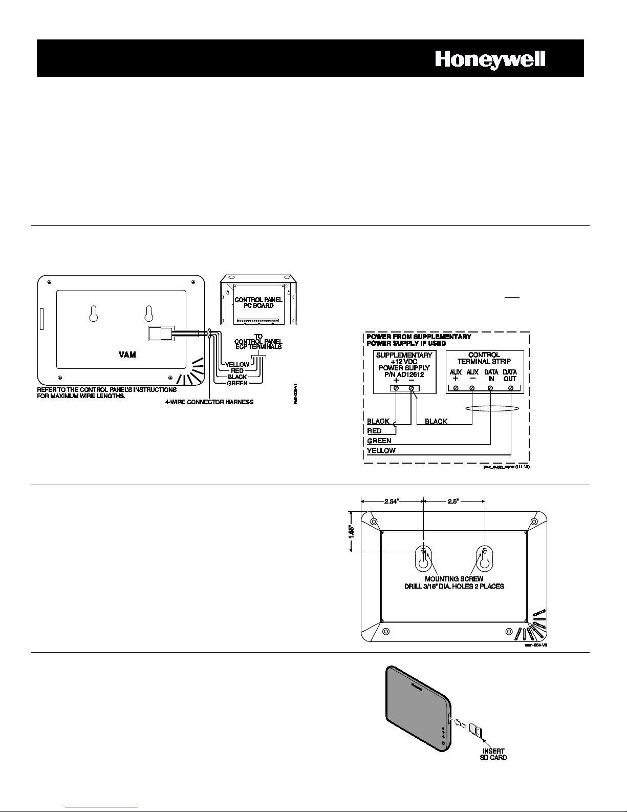
Connect VAM to the control panel’s keypad data (ECP)
terminals using a standard 4-wire keypad connector harness.
Wire Connections to the Control Panel
VAM is for indoor use only and should be mounted near the
control panel or a keypad connected to the control panel for
ease of wiring.
VAM mounts to a wall surface by hanging on two screws. See
the diagram below.
• Leave the screw heads 1/8” above the wall surface.
• If necessary, drill a hole in the wall for the wire harness to
pass through.
• Connect the wire harness to the VAM before mounting.
Refer to control panel’s installation instructions for ECP wire
limitations.
An SD card must be installed to receive automatic software
upgrades. The SD card can be left in the VAM. See Software
Upgrades section.
• Avoid touching the contacts on the card
• 4GB SD card supplied
• Supports up to 16GB SD Card
Insert the memory card (SD/SDHC Card) as shown.
\
Verify that VAM and other connected devices do not exceed the
control’s Aux Power output capability. If it does, use a
supplementary power supply as shown.
IMPORTANT: When VAM is powered from an auxiliary power
supply, always apply power to the control panel first
and then VAM.
Failure to observe this sequence results in improper operation of
VAM and may result in an ECP Error indication.
Supplementary Power Connections
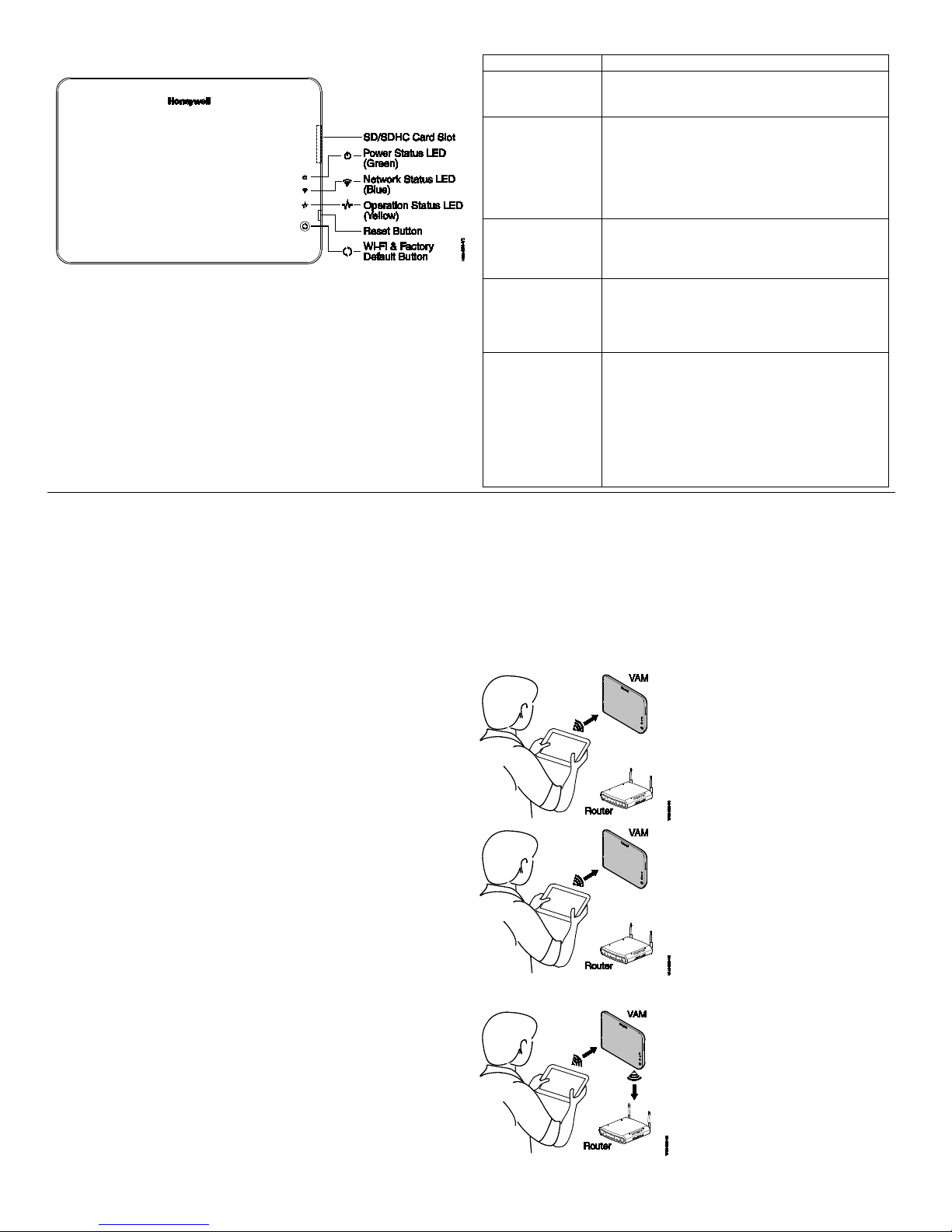
Front Panel LEDs
LED
FUNCTION
Power Status
Indicates power status. Blinking when it is
fully functional.
Network Status
When the WIFI is connected to the VAM, it will
the Wi-Fi router).
Operation Status
Normally off. It will blink slowly when there is no
wave controller not
enrollment or deletion status.
Reset Button
Press to reboot the device. The Reset button
will restore factory default settings.
Wi-Fi & Factory
• Wi-Fi Network Reset: Press and hold down
VAM to its factory default settings.
Set Up the WiFi Network
Open a web browser.
192.168.2.1
Connect device to VAM using
Connect VAM to the
(Green)
(Blue)
(Yellow)
powered up and booting. Solid green when it is
show the WIFI status through the blue LED. The
LED is blinking when VAM is booting and solid
blue when VAM is ready as AP mode (acting as
an Access Point) or connects to the internet as
STA mode (station mode, device is connected to
ECP(including ECP error) or Zresponding. Fast blinking indicates Z-wave is in
Specifications
Width: 7.58’’ (192.5mm)
Height: 5.31’’(135.0mm)
Depth: 0.53’’(13.45mm)
Voltage: 12VDC
Current: 180mA
Humidity : 93% RH, non- condensing
Default Button
Temperature:
Operating : 14˚F to 131˚F / -10˚C to 55˚C
Shipping / Storage: -40˚F to 158˚F / -40˚C to 70˚C
To set up the WiFi network for VAM, you will need the following:
• Wi-Fi enabled smart device (Tablet PC, laptop, Smartphone, etc.)
• VAM SSID and WPA2 password (located on the VAM’s label)
• VAM default IP address: 192.168.2.1
• Home router SSID and WPA2 password (typically located on the home router’s label); home router must use WPA2 encryption and
have a password (key) assigned.
NOTES: 1. Before setting up the network, set your smart device for Wi-Fi operation only (turn off 3G/4G option).
2. If the wireless router is later replaced, these steps must be repeated to connect the VAM to the new router.
can also be used to restore factory default
settings. During power up, press and hold the
reset button for more than 5 seconds, the unit
for more than 5 seconds to clear the VAM’s
Wi-Fi network connection. You then need to
reconnect the VAM to your Wi-Fi network.
• Factory Default Reset: Double press this
button, then, while the green, blue, and yellow
LEDs blink in sequence, press and hold down
this button for more than 5 seconds to set the
1. Connect smart device to VAM.
a. Power up the VAM.
b. Connect the smart device Wi-Fi to VAM using the device’s
Wi-Fi settings menu (VAM is a wireless access point).
Enter the VAM SSID: VAM_xxxx (SSID is case-sensitive)
NOTE: xxxx = the last 4 digits of the MAC address
Enter the Key (found on the VAM label “WPA2 pw” line)
2. Access VAM’s home screen.
a. Open a web browser on the smart device.
b. Go to VAM’s default IP address: 192.168.2.1
c. Optional: Z-Wave devices can be installed and added into
the system before connecting to the home router (ex. the
home router is not available at the time of VAM
installation). by using the VAM automation menus. Refer to
the Adding Z-Wave Devices section for details.
d. When ready to connect the VAM to the home router
network, go to step 3.
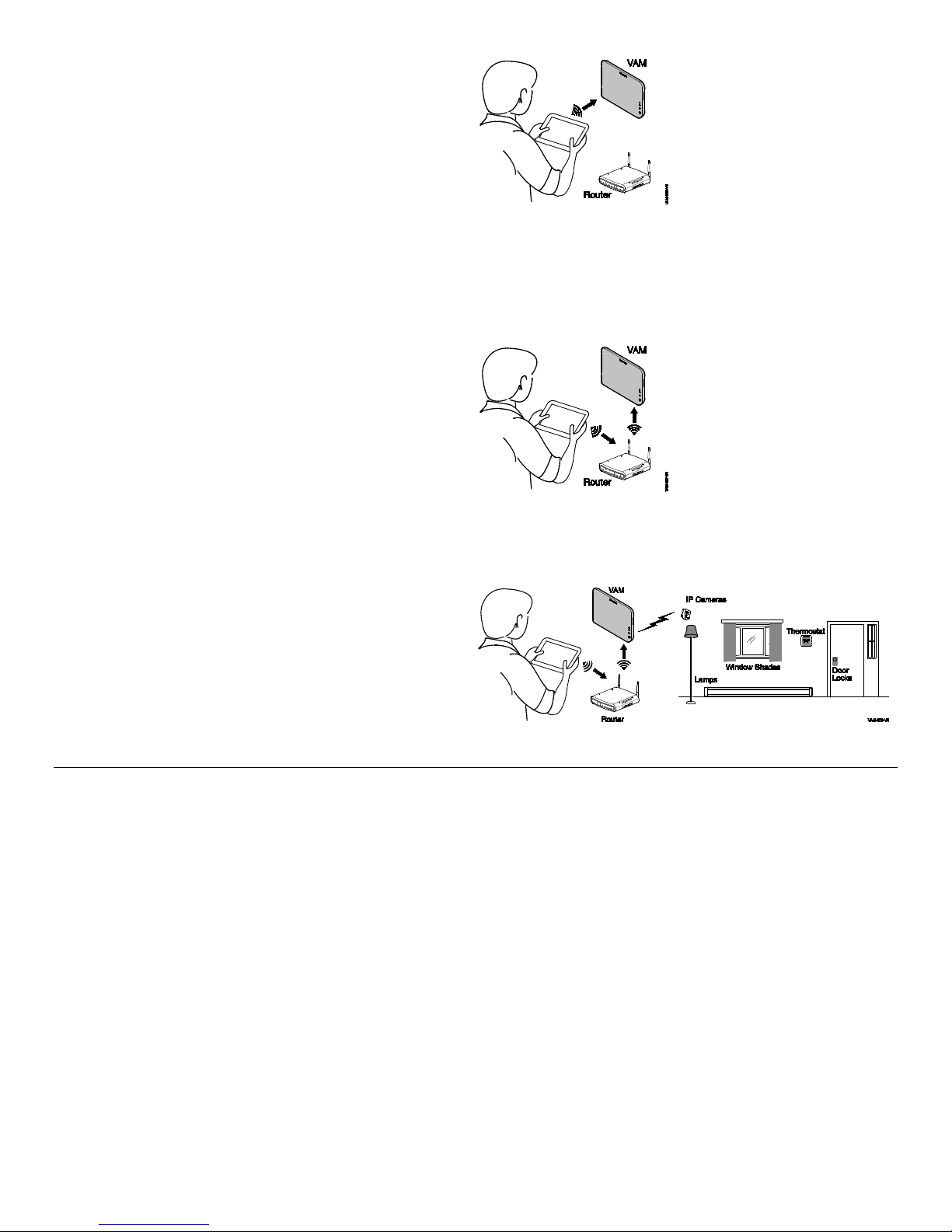
3. Connect the VAM to the home router.
a. From the main menu, click the Set Home Router button.
b. Enter the home router SSID and security key
(SSID and security key are case-sensitive).
c. Click Connect. A countdown begins and displays “Trying
to connect to the Router: xxxx, please stay in this page and
wait…” VAM can take about 2 minutes to connect to the
home router. During this time, a new network IP address is
assigned to the VAM.
d. When done, VAM connects to the assigned router.
Wi-Fi Settings Menu.
VAM SSID: VAM_xxxx
(xxxx = last 4 digits of VAM MAC ID)
Key found on VAM label.
Go to IP address:
home router by entering
home router SSID & key.
Click Connect.
– 2 –
5. Check that the smart device is connected to the
http://vam.mylanconnect.com
Reconnect device to VAM
Connect device to the
Use device to control ZWave devices.
4. Retrieve and save VAM’s network IP address.
a. Leave the browser page open.
b. Reconnect the smart device to VAM using the device’s
Wi-Fi settings menu.
c. When connected to the VAM, return to the open browser
page and click the Show IP Info link.
d. The home router’s SSID and VAM’s new IP address is
shown.
e. Select the Fixed IP option and replace the displayed IP
address with the recommended address shown. Note this
IP address for future reference. Click the Save and
Bookmark This Device button.
f. At the “Device will reboot, do you want to continue?”
prompt, click the checkmark (yes).
VAM reboots, then automatically connects to the assigned
router.
proper router.
a. Notification window displays, “Keep screen open. Go to
Wi-Fi setup and select the xxxx access point and return to
this page,” along with a countdown timer. The countdown
timer simply indicates the time remaining for the VAM to
reboot. Note that the VAM’s LEDs blink in various patterns
indicating that reboot is in progress.
b. Use the device’s Wi-Fi setup menu and make sure it is
connected to the router displayed (xxxx) in the notification.
c. Reboot is complete when the blue and green LEDs light
steady.
using Wi-Fi Settings Menu.
Return to browser page and
click Show IP Info.
home router using device
Wi-Fi Settings menu.
6. Complete the setup and bookmark VAM’s URL.
a. VAM should now be connected to the home network router
and the smart device should show the main menu.
If the main menu is not displayed, check that the smart
device is connected to the correct router.
b. Bookmark the URL displayed in the browser’s address bar
for easy access to VAM later.
c. To access VAM’s main menu at a later session, simply go
to the bookmarked address, or go to:
Program the Control Panel for use with VAM
At the control, assign an appropriate touchscreen (AUI) type device address (ECP address) for VAM, and set a partition (if
applicable).
Refer to the control panel’s programming instructions for detailed procedures.
NOTE: Do not use VAM’s Console Mode to program the control.
After enabling the VAM device address in the control panel, set the VAM to the selected address. See section below.
On VISTA® Plus series or equivalent
Use data field *189 to enable an unused device address 1, 2, 5 or 6 for VAM. Addresses 1 and 2 are enabled by default.
On VISTA® Turbo and Commercial VISTA Series
(VISTA-128BP, VISTA-128FBP, etc.)
Use #93 Menu mode to enable an unused device address.
• For older controls under Rev. 10, addresses 1-2, and 3-30 may be used.
• For VISTA Turbo series controls Rev. 10 and higher, addresses 1-30 may be used. These addresses are normally not
defaulted for AUI type devices.
If using Remote Services
Enable an appropriate RIS address in the control panel and enable the remote service (RIS) option if applicable.
– 3 –
 Loading...