

Page 1

APPLICATION
The V48 and V88 are solenoid-operated diaphragm valves
suitable for LP (Liquefied Petroleum), natural, and
manufactured gases. They are normally used on atmospheric
boilers, commercial water heaters, and rooftop heaters.
V48A,F,J; V88A,J
Diaphragm Gas Valves
PRODUCT DATA
FEATURES
• Line voltage, 2-wire thermostat or controller used with
a V48; V88 used with 24V thermostat.
• Valves provide slow opening and fast closing.
• Two second maximum closing time.
• V48J, V88J rated for 150°F (66°C) ambient temperature.
• V48F rated for 5 psi (lb. per sq. in.) (34.5 kPa). V48A
and V88A rated for either 1/2 or 1 psi (3.4 or 6.9 kPa),
depending on model. V48J and V88J rated for 1 psi
(6.9 kPa).
• One model for natural and LP gases.
• Wide range of sizes and capacities.
• Firm closing; diaphragm is both weight and spring
loaded.
• Valve closes on power failure; recommended for final
shutoff service.
• Adjustable or fixed bleed orifices available for
installation by OEM.
• Valve position indicator on 1-1/4 in. V48A2227 and 2 in.
V48F1103 Valves.
® U.S. Registered Trademark
© 2004 Honeywell International Inc.
All Rights Reserved
Contents
Application ........................................................................ 1
Features ........................................................................... 1
Specifications ................................................................... 2
Ordering Information ........................................................ 2
Installation ........................................................................ 4
Wiring ............................................................................... 6
Operation .......................................................................... 8
Checkout and Troubleshooting ......................................... 9
Service Information .......................................................... 10
60-2080—9
Page 2

V48A,F,J; V88A,J DIAPHRAGM GAS VALVES
SPECIFICATIONS
Models:
V48A (120 Vac) or V88A (24 Vac) solenoid operated
diaphragm valves for 1/2 or 1 psi (3.4 or 6.9 kPa) maximum
operating pressure.
V48F (120 Vac) solenoid operated diaphragm valve for 5 psi
(34.5 kPa) maximum operating pressure.
V48J (120 Vac) or V88J (24 Vac) solenoid operated
diaphragm valves for 1 psi (6.9 kPa) operating pressure
and 150°F maximum ambient temperature.
Type of Gas: Suitable for liquefied petroleum (LP), natural,
manufactured, and sulfur-bearing gases.
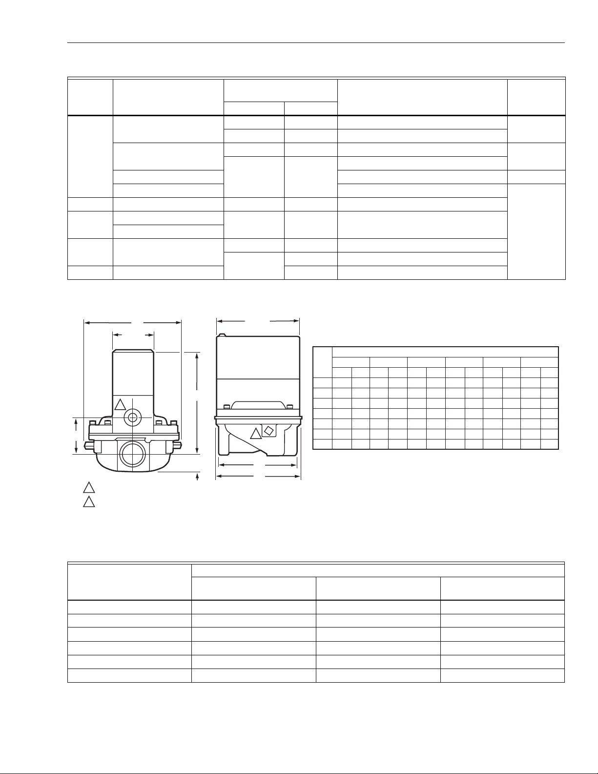
Valve Capacity: See table in Fig. 2.
Valve Pattern: Straight-through, non-offset.
Valve Body Material: Die-cast aluminum.
Pilot Tapping (see Table 1 for thread type):
3/4 through 1-1/2 inch valves: 1/8-27 NPT or 1/8-28 BSP.PI.
2 through 3 inch valves: 1/4-18 NPT.
Bleed Tapping (see Table 2 for thread type): 1/8-27 NPT or
1/8-28 BSP.PI.
Valve Opening Time:
Five seconds maximum at 2 oz/in.
Adjustable bleed valve assembly or fixed bleed orifices
available for longer opening time (NPT threads only; see
Accessories).
Valve Closing Time (on power failure; measured at
2 oz/in.
Maximum Operating Pressure: See Table 2.
Power Consumption (maximum): 9 watts or 15 VA.
Ambient Temperature Rating:
V48A,F and V88A: 32°F to 125°F (0°C to 52°C).
V48J and V88J: 32°F to 150°F (0°C to 66°C).
2
[0.86 kPa] pressure): 2 seconds maximum.
2
(0.86 kPa) pressure.
Thermostat Heat Anticipator Setting: For 60 Hz V88, set at
0.6A.
Dimensions: See Fig. 1.
Weight: See Table 1.
Table 1. Valve Weight.
Pipe Size (in.) lb kg
3/4 2-1/2 1.13
1 3 1.36
1-1/4 3-1/2 1.59
1-1/2 4 1.81
2 9 4.08
2-1/2 8-1/2 3.86
3 9-1/2 4.31
Approvals: (60 Hz models only):
Underwriters Laboratories Inc. Listed: File No. MH1639;
Guide No. YIOZ.
CSA 158158-2500005576 (Z21.21-CSA 6.5).
NOTE: All models rated at 50 Hz and all models with BSP.PI
Optional Feature: Valve position indicator is available on
Replacement Coil Assemblies:
116930: 24V, 60 Hz V88A
116931: 120V, 60 Hz V48A.
116932: 220V, 50 Hz V48A
116932: 240V, 60 Hz V48A
118888: 24V, 60 Hz V88J
139937: 120V, 60 Hz V48J
a
are not compatible with old style valve bodies.
threads are not CSA Design Certified.
1-1/4 in. V48A2227 and 2 in. V48F1103.
a
These V48/V88 bonnet assemblies and solenoid operators
Maximum Fluid Temperature:
V48A,F; V88A: 125°F (52°C).
V48J; V88J: 150°F (66°C).
ORDERING INFORMATION
When purchasing replacement and modernization products from your TRADELINE® wholesaler or distributor, refer to the
TRADELINE® Catalog or price sheets for complete ordering number.
If you have additional questions, need further information, or would like to comment on our products or services, please write or
phone:
1. Your local Honeywell Automation and Control Products Sales Office (check white pages of your phone directory).
2. Honeywell Customer Care
1885 Douglas Drive North
Minneapolis, Minnesota 55422-4386
In Canada—Honeywell Limited/Honeywell Limitée, 35 Dynamic Drive, Scarborough, Ontario M1V 4Z9.
International Sales and Service Offices in all principal cities of the world. Manufacturing in Australia, Canada, Finland, France,
Germany, Japan, Mexico, Netherlands, Spain, Taiwan, United Kingdom, U.S.A.
60-2080—9 2
Page 3
V48A,F,J; V88A,J DIAPHRAGM GAS VALVES
Table 2. Models Available.
Maximum Operating
Model Voltage and Frequency
Pressure
psi kPa
Pipe Size (in.)
Thread
Type
V48A 100V, 50 Hz 1/2 3.4 1, 1-1/4, 1-1/2 BSP.PI
16.92
120V, 60 Hz 1/2 3.4 3/4, 1, 1-1/4, 1-1/2 NPT
1 6.9 1, 1-1/4, 1-1/2, 2, 2-1/2, 3
220V, 50 Hz 1, 1-1/4, 1-1/2, 2, 3 BSP.PI
240V, 50 Hz 2 NPT
V48F 120V, 60 Hz 5 34.5 2
V48J 120V, 60 Hz 1 6.9 3/4, 1, 1-1/4, 1-1/2, 2
110V, 50 Hz
V88A 24V, 60 Hz 1/2 3.4 3/4, 1, 1-1/4, 1-1/2
1 6.9 3/4, 1, 1-1/4, 1-1/2, 2, 2-1/2, 3
V88J 24V, 60 Hz 6.9 1, 1-1/4
a
A valve position indicator is on 1-1/4 in. V48A2227 and 2 in. V48F1103 Valves. BSP.PI—British Standard Parallel Internal
Threads; NPT—American Standard Taper Pipe Threads.
a
C
1-13/16
(46)
A
1
E
B
1
BLEED TAPPING: 1/8-27 NPT, OR 1/8-28 BSP. PL.
2
PILOT TAPING (2): 1/8-27 NPT FOR 3/4 THROUGH 1-1/2 IN. SIZES, 1/4-18 NPT FOR 2 THROUGH 3 IN. SIZES; OR 1/8-28 BSP.
PL FOR 1 THROUGH 1-1/2 IN. SIZES, 1/4-19 BSP.PL FOR 2 THROUGH 3 IN SIZES.
3-11/16
(94)
2
D
F
VALVE
SIZE
(IN.)
3/4
1-1/4
1-1/2
2-1/2
ABCDEF
IN. MM IN. MM IN. MM IN. MM IN. MM IN.
4-11/16
119.1
3/4
1
5-1/16
128.6
1
5-9/16
141.3
1-1/4
5-9/16
141.3
1-1/4
2
6-15/16
176.2
2-1/4
6-15/16
176.2
2-1/4
3
6-15/16
176.2
2-1/4
APPROXIMATE DIMENSIONS
19.1
4-5/8
117.5
25.4
5
127.0
31.8
5-7/8
149.2
31.8
5-7/8
149.2
57.2
9-1/2
241.3
57.2
9-1/2
241.3
57.2
9-1/2
241.3
3-1/2
3-11/16
5-5/16
5-5/16
8-3/8
8-3/8
8-3/8
88.9
93.7
134.9
134.9
212.7
212.7
212.7
1-5/8
2-1/16
2-3/8
2-3/8
3-9/16
3-9/16
3-9/16
41.3
52.4
60.3
60.3
90.5
90.5
90.5
3-13/16
4-5/16
5-5/16
5-5/16
5-5/16
9-5/16
9-5/16
M8487
MM
96.8
109.5
134.9
134.9
236.5
236.5
236.5
Fig. 1. Mounting dimensions of V48A,F,J and V88A,J Diaphragm Gas Valves in in. (mm).
a
Table 3. Extending Valve Opening Time
By Adding a Bleed Orifice.
Valve Opening Time (seconds)
Valve Size (in.)
No Orifice
Orifice No. 122160,
0.018 in. (0.46 mm)
Orifice No. 124674,
0.011 in. (0.28 mm)
1123
1-1/4 1 5 6
1-1/2 1 5 6
241532
2-1/2 4 23 37
352437
a
Time to reach 80% gas flow at fully open position. Inlet pressure; 4.2 in. wc (1.05 kPa) for 1 to 2 in. valves; 5 in. wc (1.25 kPa)
for 2-1/2 and 3 in. valves. Pressure drop across valves at fully open position. 0.2 in. wc (0.05 kPa) for 1 to 2 in. valves; 1 in. wc
(0.25 kPa) for 2-1/2 and 3 in. valves.
3 60-2080—9
Page 4

V48A,F,J; V88A,J DIAPHRAGM GAS VALVES
Accessories:
Transformer AT72D: (40 VA) for all V88 models.
126590 Adjustable Bleed Valve Assembly: Consists of
adjustable bleed valve with sleeve and compression nut for
connecting to 1/4 in. tubing; see Fig. 8.
Bleed Orifice: Fixed (see Table 2 for appropriate size):
124674 Orifice: 0.011 in. (0.28 mm) diameter.
122160 Orifice: 0.018 in. (0.46 mm) diameter.
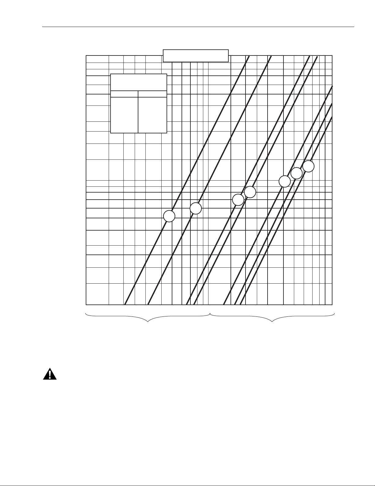
Gas Valve Sizing
1. Check the burner nameplate for (a) the type of gas
used, and (b) the gas flow capacity. The capacity will be
listed in Btu/h (Btu per hour) or in cf/h (cubic feet per
hour).
2. Call the gas utility for information on (a) the specific
gravity (sp gr) and (b) Btu per cubic feet (Btu/cu ft) for
type of gas used.
3. Find the capacity in cf/h. If the capacity is listed in Btu/h,
convert to cf/h by the following formula.
Capacity in cf/h = Btu/h (from burner nameplate)
Btu/cu ft (from gas utility)
4. For gases with specific gravities other than 0.64,
multiply the burner cf/h by the conversion factor in Table
4.
5. Use the corrected burner capacity in cf/h when
determining the gas valve size in Fig. 2.
6. Determine the maximum pressure drop across the
valve, and draw a horizontal line at this pressure in Fig.
2.
Table 4. Conversion Factors.
Average Specific
Type of Gas
Manufactured 0.60 .968
Mixed 0.70 1.046
LP—Propane 1.53 1.546
LP—Butane 1.98 1.759
7. Draw a vertical line in Fig. 2 at the capacity (cf/h) previously determined. Use the corrected capacity for a gas
with a specific gravity other than 0.64.
8. Use the valve size at the intersection of the horizontal
and vertical lines. If the intersection is between valve
sizes, use the next higher valve size to the right.
Gravity Divide cfh by:
To Size Two Identical Valves Piped in Series
1. Find the cf/h for the type of gas used.
2. Consider both valves as one unit. Determine the total
maximum pressure drop across the unit.
3. Find the pressure drop across the first valve by
assuming it to be 45 percent of the total pressure drop.
4. Find the valve size from Fig. 2.
5. The second valve will be the same size as the first
valve.
INSTALLATION
When Installing This Product…
1. Read these instructions carefully. Failure to follow them
could damage the product or cause a hazardous
condition.
2. Check the ratings given in the instructions and on the
product to make sure the product is suitable for your
application.
3. Installer must be a trained, experienced, flame
safeguard control technician.
4. After installation is complete, check out product
operation as provided in these instructions.
WARNING
Explosion or Electrical Shock Hazard.
Can cause severe injury, death or property
damage.
1. Turn off gas supply before starting installation.
2. Disconnect power supply before beginning
installation to prevent electrical shock and
equipment damage.
3. Do not remove seal over valve inlet or outlet until
ready to connect piping.
4. Do not bend tubing at the valve after the
compression nut is tightened because this may
result in gas leakage at the connection.
5. Install valve in a horizontal pipe line in any upright
position with the gas flow in the direction indicated
by the arrow on the casting.
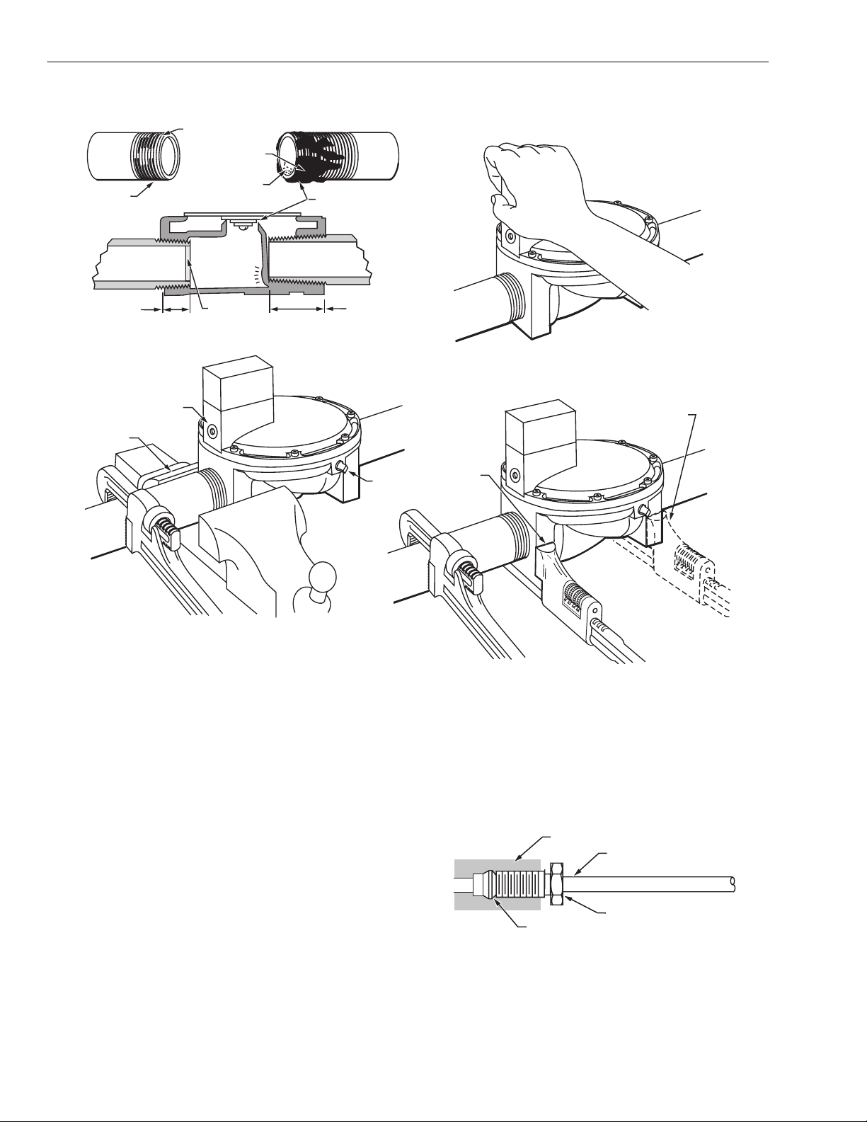
Prepare Piping and Install Valve (Fig. 3)
1. Use new, properly reamed pipe free from chips.
2. Do not thread pipe too far. Valve distortion or
malfunction may result from excess pipe in valve.
3. Apply good quality pipe dope, putting a moderate
amount on the male threads only. If pipe dope lodges on
the valve seat, it will prevent proper closure. If using
liquefied petroleum (LP) gas, use pipe dope resistant to
action of LP gas.
4. Install valve in a horizontal pipe line in an upright
position with the gas flow in the direction indicated by
the arrow on the casting.
5. Apply a parallel jaw wrench only to the flat next to the
pipe being inserted. A wrench applied to the valve body
itself or to the end farthest from the pipe being inserted
may distort the casting, causing a malfunction.
6. The gas flow MUST be in the same direction as the
arrow on the bottom of the valve body.
60-2080—9 4
Page 5
V48A,F,J; V88A,J DIAPHRAGM GAS VALVES
[2.5] 10
9
[2.0] 8
7
[1.5] 6
5
[1.0] 4
[0.75] 3
2.5
[0.5] 2
1.5
[0.25] 1.0
0.9
[0.2] 0.8
0.7
[0.15] 0.6
0.5
PRESSURE DROP—INCHES W.C. [kPa]
[0.1] 0.4
A.G.A.RATING FOR
0.64 SP. GR. GAS AT
1 IN. PRESSURE DROP
VALVE SIZE CAPACITY
3/4 IN.
1 IN.
1-1/4 IN.
1-1/2 IN.
2 IN.
2-1/2 IN.
3 IN.
668 cf/h
1021 cf/h
2100 cf/h
2400 cf/h
4178 cf/h
5100 cf/h
5562 cf/h
PRESSURE DROP VS. CAPACITY
FOR 0.64 SP GR. GAS
1
3/4
3
2-1/2
2
1-1/2
1-1/4
[0.075] 0.3
0.25
[0.05] 0.2
0.15
[0.025] 0.1
1 1.5 2 2.5 3 4 5 6 7 8 9 10 1.5 2 2.5 3 4 5 6 7 8 9 10
MULTIPLY BY 100
CAPACITY IN CUBIC FEET PER HOUR (cf/h)
FOR GAS WITH SPECIFIC GRAVITY OF 0.64
Fig. 2. Pressure drop vs. capacity chart for sizing gas valves.
WARNING
Explosion or Fire Hazard.
Can cause severe injury, death or property
damage.
If the flow is not in the same direction as the arrow on
the bottom of the gas valve, the valve may not shut off,
causing an accumulation of gas in the combustion
chamber.
MULTIPLY BY 1000
3
[1 cf/h = 0.0283 m
/hr]
Connect Pilot and Bleed Gas Tubing (Fig. 4)
1. Square off and remove burrs from end of the tubing.
Bend tubing to the desired form for routing to the pilot
burner. Do not bend tubing at the valve after the
compression nut is tightened because this may result in
gas leakage at the connection.
2. Unscrew brass compression fitting from pilot gas
tapping (Fig.4). Slip the fitting over the tubing and slide
out of the way.
M8491
5 60-2080—9
Page 6
V48A,F,J; V88A,J DIAPHRAGM GAS VALVES
EXCESS DOPE
MAY BLOCK
DISC OFF
VALVE
SEAT
LOOSE CHIPS
RIGHT
NORMAL FULL
THREAD
2 CLEAN
THREADS,
MODERATE
AMOUNT
OF DOPE
WRONG
TOO LONG,
DISTORTS VALVE
SEAT
WRONG
NEVER USE VALVE
AS A HANDLE
RIGHT
NORMAL FULL
THREAD
RIGHT
VISE GRIPS
END NEXT
TO PIPE
BEING
INSERTED
BLEED
GAS
TAPPING
REAM PIPE,
BLOW OUT
CHIPS (THEY MAY
LODGE ON SEAT)
WRONG
TOO LONG,
DISTORTS VALVE
SEAT
Fig. 3. Preparing piping and installing valve.
IMPORTANT:
When replacing a valve, cut off old compression
fitting and replace with a new compression fitting.
Never use the old compression fitting because it may
not provide a tight gas seal.
3. Push tubing into the pilot gas tapping on the outlet end
of the valve until it bottoms. While holding tubing all the
way in, slide fitting into place and engage threads—turn
until finger tight. Then use wrench and tighten one turn
beyond finger tight.
4. Connect other end of tubing to pilot burner according to
pilot burner manufacturers instructions.
5. If required, connect the tubing to bleed gas tapping
(Fig. 3 and 4) as described in step 3. Connect other end
of bleed tubing to main burner or to outside atmosphere.
PILOT GAS
TAPPING
WRONG
WRENCH HERE
RIGHT
WRENCH
CORRECTLY
APPLIED
NEXT TO
PIPE BEING
INSERTED
STRAINS VALVE BODY
M7299
WIRING
1. Disconnect the power supply before making wiring
connections to prevent electrical shock and equipment
damage.
GAS VALVE
TUBING
GAS FLOW
COMPRESSION FITTING
SLEEVE CLINCHES AROUND TUBING
AS NUT IS TIGHTENED
M7300
60-2080—9 6
Fig. 4. Connecting tubing to pilot for bleed gas tapping.
2. All wiring must comply with applicable electrical codes,
ordinances, and regulations. Use NEC Class 1 (line
voltage) wiring.
Page 7
V48A,F,J; V88A,J DIAPHRAGM GAS VALVES
3. For normal installations, use moisture-resistant No. 14
wire suitable for at least 167°F (75°C) if using a flame
safeguard primary control, or for at least 194°F (90°C) if
using a flame safeguard programming control.
4. For high temperature installation, use moisture-resistant
No. 14 wire selected for a temperature rating above the
maximum operating temperature.
5. Check the power supply circuit. The voltage and
frequency must match those of the valve.
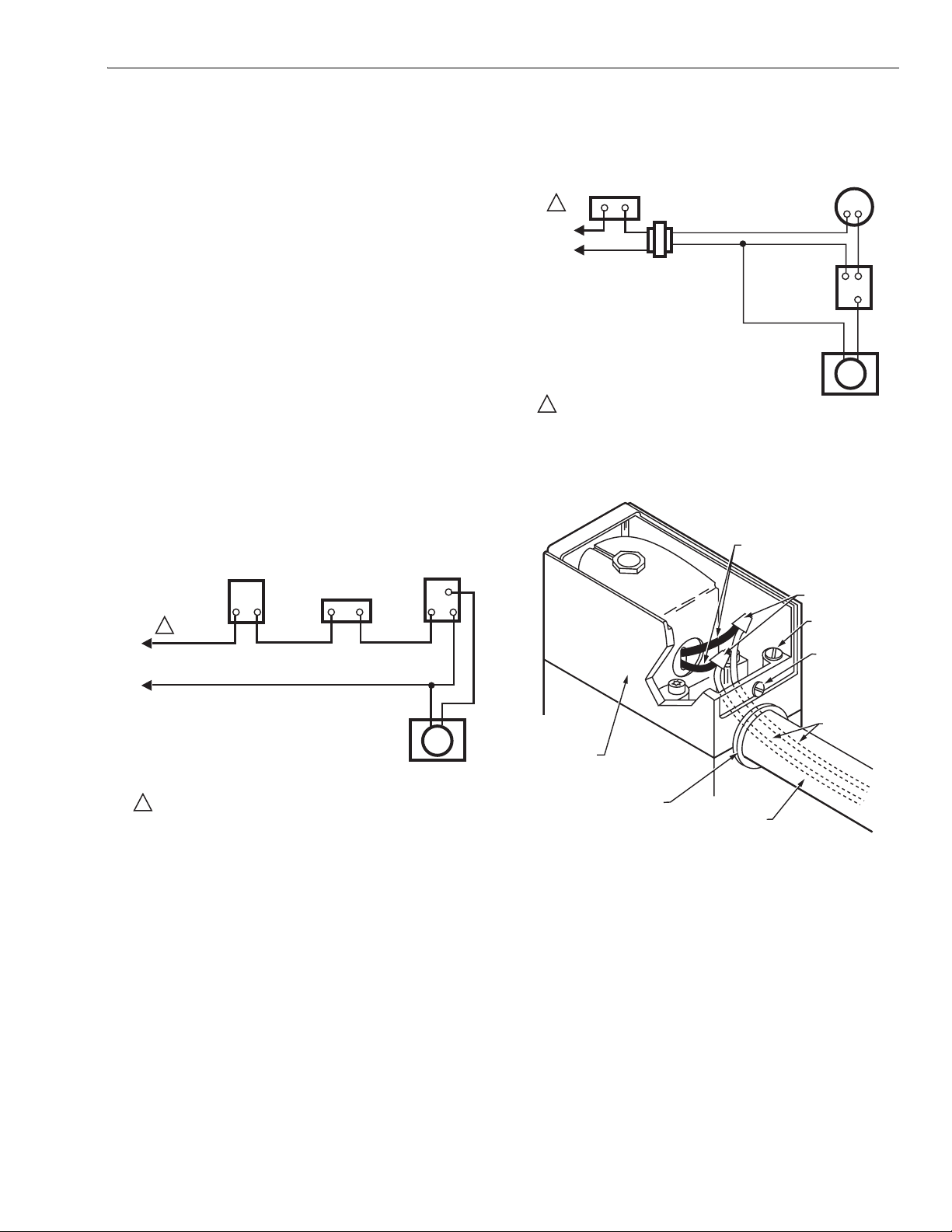
6. Refer to Fig. 5 or 6 for typical field wiring connections.
Follow the burner manufacturers wiring diagram if
provided.
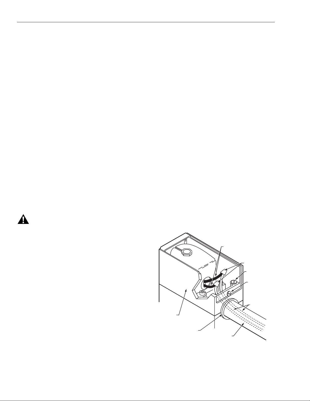
7. Make wiring connections inside the actuator housing
(Fig. 7):
a. Loosen the cover screw in the front of the actuator
housing, and remove the housing cover.
b. If a conduit is required, run the conduit through the
opening in the actuator housing, and run the
external wires through the conduit.
c. Using solderless connectors, connect the external
wires to the two 6 in. (152.4 mm) black leadwires
(from the coil).
d. Locate the connections inside the actuator housing.
e. Replace the housing cover, and tighten the cover
screw holding it to the actuator housing.
8. Recheck the wiring circuits before putting the valve into
service.
FLAME
SAFEGUARD
CONTROL
L1
(HOT)
L2
LINE VOLTAGE
THERMOSTAT OR
CONTROLLER
LIMIT(S)
1
connection. Then alternately energize and de-energize the
valve actuator, and adjust the screw on the bleed valve for the
desired valve opening time.
LIMIT(S)
1
L1
(HOT)
L2
TRANSFORMER
V88
VALVE ACTUATOR
(BLACK LEAD WIRES)
1
POWER SUPPLY. PROVIDE DISCONNECT MEANS AND OVERLOAD
PROTECTION AS REQUIRED.
24 VOLT
THERMOSTAT
24V
FLAME
SAFEGUARD
CONTROL
M8488A
Fig. 6. Typical wiring diagram for V88.
6 IN. [152.4 MM] INTERNAL
BLACK LEADWIRES
(FROM COIL)
SOLDERLESS
CONNECTORS
GROUNDING
SCREW
COVER
SCREW
VALVE ACTUATOR
(BLACK LEAD WIRES)
1
POWER SUPPLY. PROVIDE DISCONNECT MEANS AND OVERLOAD
PROTECTION AS REQUIRED.
M8490A
Fig. 5. Typical wiring diagram for V48.
Installation of an Optional Adjustable Bleed
Valve (Fig. 8).
NOTE: This device is not available for valves with BSP.PI
threads.
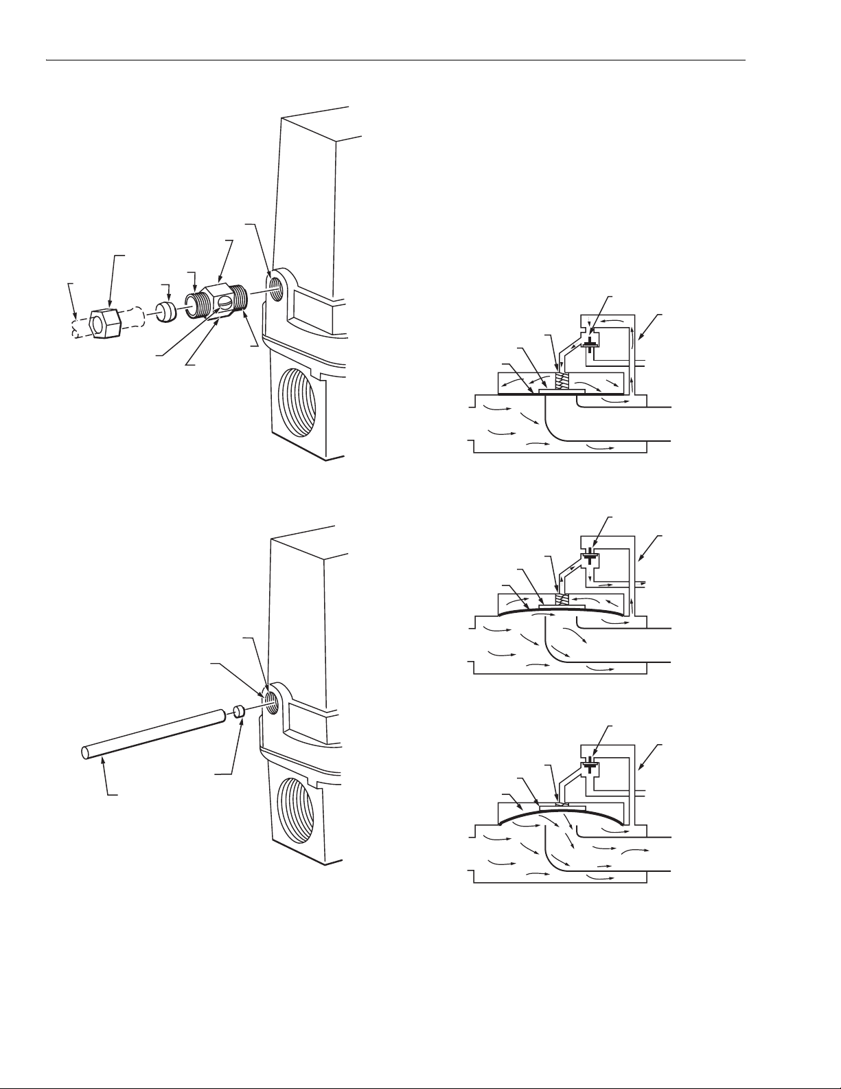
Screw the 126590 Adjustable Bleed Valve into the tapping
marked BLEED. Be sure to screw the end with the 1/8-NPT
threads into the BLEED tapping. Complete the bleed line
EXTERNAL
WIRES
ACTUATOR
HOUSING
OPENING IN
ACTUATOR
HOUSING
CONDUIT
(IF REQUIRED)
M7302
Fig. 7. Making wiring connections.
Installation of an Optional Bleed Orifice
(Fig. 9)
NOTE: The orifice tool cannot be used on valves with
BSP.PI threads.
Press the selected bleed orifice (see Table 2) over the 1/8 in.
diameter dowel and press until the orifice cup bottoms in the
bleed port. Complete the connection of the bleed tubing.
7 60-2080—9
Page 8
V48A,F,J; V88A,J DIAPHRAGM GAS VALVES
BLEED TAPPING
126590 ADJUSTABLE BLEED VALVE
COMPRESSION NUT
1/4 INCH
TUBING
ADJUSTING SCREW
7/16-24 UNS
SLEEVE
1/8-27 NPT
7/16 INCH HEX
OPERATION
Operation of the V48 and V88 Valves
(Fig. 10)
When the controller is not calling for heat, the coil is
de-energized. The plunger in the 3-way actuator is in the
DOWN position so the bleed port is closed and the supply port
is open. Gas flows into the top part of the valve. The gas
pressure on top of the diaphragm, the weight, and the spring
hold the valve closed.
PLUNGER
GAS
SUPPLY
SPRING
WEIGHT
DIAPHRAGM
PASSAGE
BLEED
PORT
M7290
Fig. 8. Installing optional 126590 adjustable bleed valve.
BLEED PORT
1/8-27 NPT
BLEED ORIFICE
(SELECTED)
1/8 INCH DIAMETER ROD
MAIN
GAS
SUPPLY
WEIGHT
DIAPHRAGM
MAIN
GAS
SUPPLY
WEIGHT
DIAPHRAGM
VALVE CLOSED
SPRING
VALVE OPENING
SPRING
PLUNGER
PLUNGER
TO BURNER
GAS
SUPPLY
PASSAGE
BLEED
PORT
TO BURNER
GAS
SUPPLY
PASSAGE
BLEED
PORT
M7298A
Fig. 9. Installing optional bleed orifice.
60-2080—9 8
MAIN
GAS
SUPPLY
VALVE OPEN
TO BURNER
M8489
Fig. 10. Operation of V48 and V88 diaphragm gas valves.
On a call for heat, the controller contacts close and the coil is
energized. This pulls the plunger to the UP position, opening
the bleed port and closing the supply port. The gas in the top
Page 9
V48A,F,J; V88A,J DIAPHRAGM GAS VALVES
of the valve flows out through the bleed port. This reduces the
pressure on top of the diaphragm, allowing the gas pressure
below to lift the diaphragm and open the valve.
When all the gas has bled off the top of the diaphragm, the
valve is fully open, permitting gas flow to the main burner.
After the controller is satisfied, the procedure is reversed. The
controller contacts open so the coil is de-energized. The
plunger is released, moving to the DOWN position. This
closes the bleed port and opens the supply port so gas flows
again into the top port of the valve. As the gas pressure on top
of the diaphragm increases, the diaphragm begins to close.
When the pressures on both sides of the diaphragm are
balanced, the valve will be closed. The weight and spring help
to close the valve. If the gas supply fails and there is no
pressure below the diaphragm, the weight and spring will
close the valve.
In the event of a power failure during automatic operation, all
V88 and V48 valves will close. Normal operation will be
resumed upon power restoration.
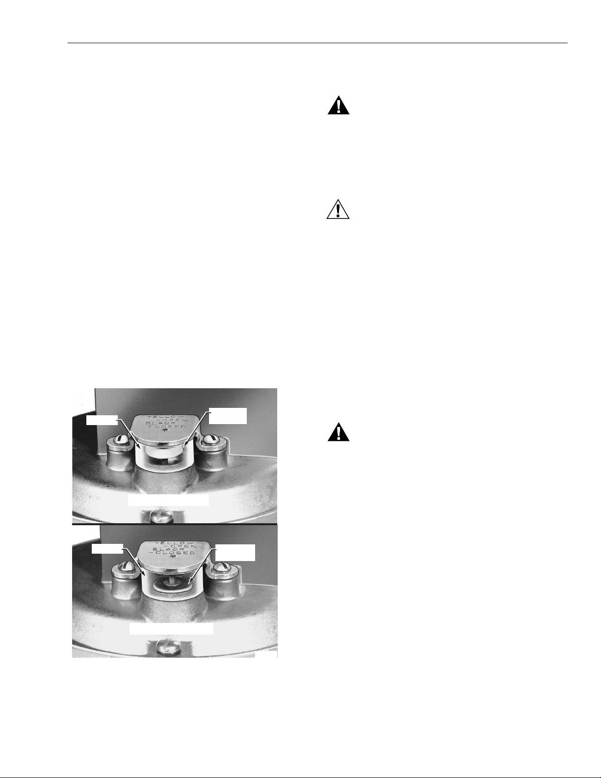
Operation of the Valve Position Indicator
(Fig. 11)
An optional valve position indicator is available in the 1-1/4 in.
V48A2227 and 2 in. V48F1103 Valves. When the valve is
open, a yellow disk shows in the window. When the valve is
closed, only the black top of the disk is visible.
CHECKOUT AND TROUBLESHOOTING
WARNING
Explosion Hazard.
Can cause severe injury, death or property
damage.
Do not allow fuel to accumulate in the combustion
chamber. If fuel is allowed to enter the chamber for
longer than a few seconds without igniting, an
explosive mixture could result.
CAUTION
Equipment Damage Hazard.
Can cause equipment damage and improper
operation.
1. Do not put the system into service until you have
satisfactorily completed all applicable tests
described in the Checkout section of the
instructions for the flame safeguard control, and any
other tests required by the burner manufacturer.
2. Close all manual fuel shutoff valves as soon as
trouble occurs.
Checkout
Start the system and observe its operation through at least
one complete cycle to be sure the valve functions as
described in the Operation section.
WINDOW
WINDOW
VALVE OPEN
VALV E C L O S ED
YELLOW
DISC
BLACK TOP
OF DISC
M18856
Troubleshooting
WARNING
Electrical Shock Hazard.
Can cause severe injury or death.
Use utmost care during troubleshooting. Line voltage
is present at the actuator for a V48 Valve, and is
present in all controller circuits for all V48 and V88
Val ves.
IMPORTANT:
Do not assume that the valve must be replaced until
all other sources of trouble have been eliminated.
If the valve will not open when the thermostat or
controller is calling for heat:
1. Check that there is voltage at the valve actuator (black
leadwires, Fig. 7). Be careful—there should be line
voltage at the actuator of a V48.
2. If there is no voltage at the actuator, first make sure line
voltage power is connected to the master switch, the
master switch is closed, and overload protection (circuit
breaker, fuse, or similar device) has not opened the
power line.
3. For a V88 only: If a line voltage power is okay, check the
transformer. Replace it if necessary.
Fig. 11. Valve position indicator (optional).
9 60-2080—9
Page 10
V48A,F,J; V88A,J DIAPHRAGM GAS VALVES
4. If there is still no voltage at the actuator, make sure all
the appropriate contacts in the thermostat (or
controller), limit(s), and flame safeguard control are
closed. If one or more is open, determine the cause(s)
and correct the con-dition(s) before proceeding.
5. If there is proper voltage at the valve actuator but the
valve still does not open, first check that the gas
pressure at the valve is normal. Then make sure that
the bleed line is unobstructed.
6. If the gas pressure and bleed line are okay but the valve
still does not open, replace the coil assembly. (Refer to
the Specifications section for the proper part number,
and to the Service Information section for the proper
procedure.)
7. If you replace the coil assembly and the valve still does
not open, replace the valve.
If the valve will not close when one or more of the
appropriate contacts in the thermostat (or
controller), limit(s), or flame safeguard control is
open:
1. Make sure that the gas flow is in the direction of the
arrow on the valve body.
2. Make sure the valve actuator is wired in the correct
circuit. Open the master switch to remove power from
the valve actuator. If the valve closes now, the actuator
may not be wired properly.
3. Look for a short in the electrical circuit.
SERVICE INFORMATION
WARNING
Electrical Shock Hazard.
Can cause severe injury or death.
1. Only qualified service technicians should attempt to
service or repair flame safeguard controls and
burner systems.
2. Open the master switch before replacing the coil
assembly or the valve. Line voltage is present in the
electrical circuits to the valve.
Scheduled Inspection and Maintenance
A schedule should be set up and followed for periodic
inspection and maintenance for the burner and all other
controls and the valve(s). Refer to the instructions for the
flame safeguard control for more information.
Replacing the coil assembly (Figs. 12
through 15)
1. Open the master switch to disconnect all power to the
valve actuator.
2. Loosen the cover screw in the front of the actuator
housing (Fig. 12) and remove the housing cover.
3. Disconnect the external wires from the two internal
black leadwires (Fig. 12).
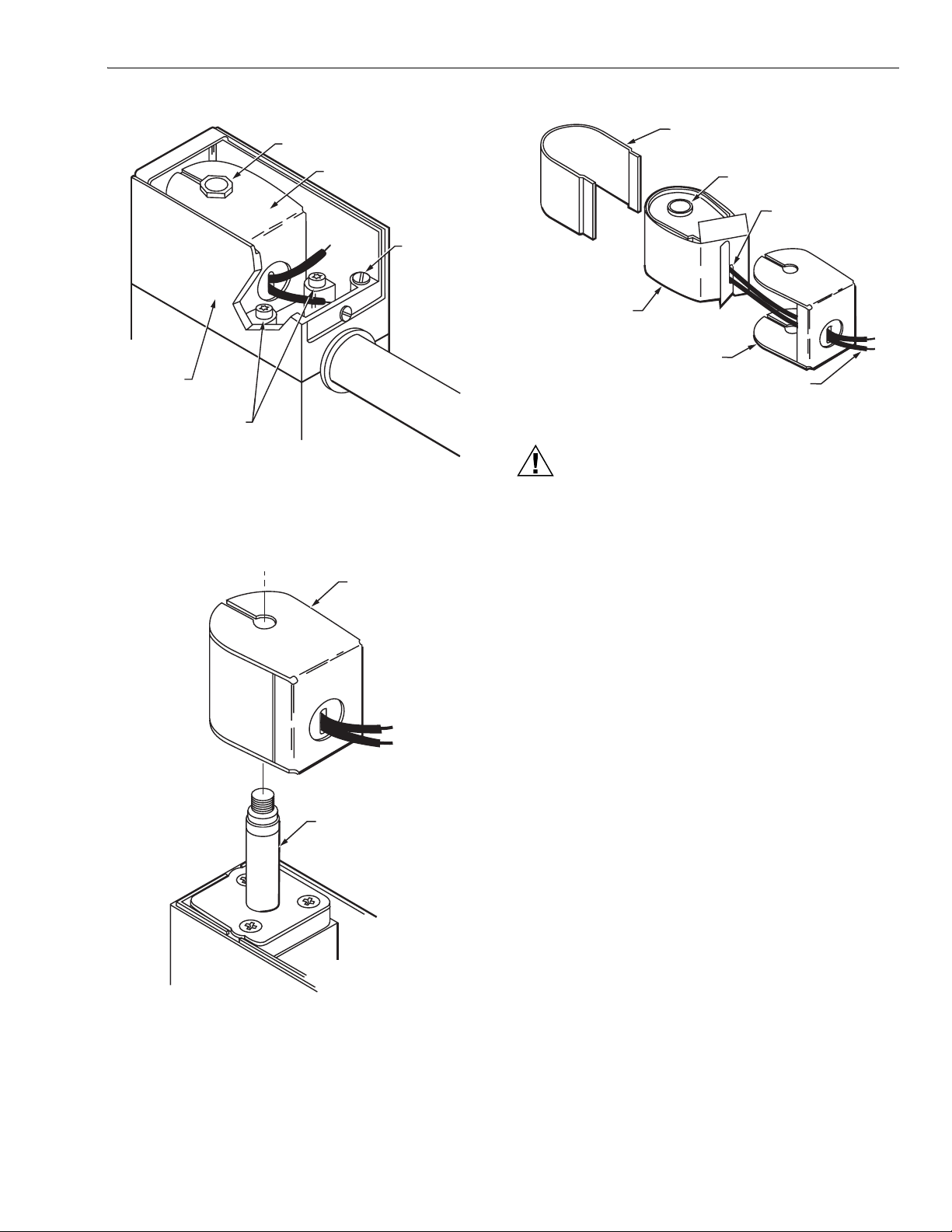
4. Remove the two torx screws inside the actuator housing
(Fig. 13) and lift off the housing.
5. Remove the holding nut from the top of the coil
assembly (Fig. 13).
6. Lift the coil assembly straight up and off the plunger
tube assembly (Fig. 14).
7. Snap out the wraparound metal cover and remove the
metal base (Fig. 15). Save these parts for the
replacement coil.
8. Carefully unhook the cardboard insulator (Fig. 15) and
remove it. Save the insulator for the replacement coil.
9. Make sure the new coil assembly has the same part
number as the old one; then discard the old coil
assembly.
10. Wrap the cardboard insulator around the new coil
assembly and carefully hook it together around the two
black leadwires (Fig. 15).
11. Insert the two black leadwires through the opening in
the metal base, and insert the new coil assembly into
the metal base (Fig. 15).
12. Snap the wraparound metal cover into place around the
new coil assembly (Fig. 15).
13. Slip the new coil assembly over the plunger tube
assembly (Fig. 14).
14. Replace the holding nut on top of the coil assembly (Fig.
13) and tighten it securely.
15. Replace the actuator housing and tighten the two torx
screws holding it in place (Fig. 13).
16. Reconnect the external wires to the two internal black
leadwires (Fig. 12).
17. Replace the housing cover, and tighten the cover screw
holding it to the actuator housing (Fig. 12).
18. Close the master switch.
19. Test the valve to make sure it opens and closes as
described in the Operation section.
20. Verify proper operation after servicing.
6 IN. [152.4 MM] INTERNAL
BLACK LEADWIRES
(FROM COIL)
SOLDERLESS
CONNECTORS
GROUNDING
SCREW
COVER
SCREW
EXTERNAL
WIRES
ACTUATOR
HOUSING
OPENING IN
ACTUATOR
HOUSING
CONDUIT
(IF REQUIRED)
M7302
Fig. 12. Wiring connections and actuator housing.
60-2080—9 10
Page 11
HOLDING NUT
V48A,F,J; V88A,J DIAPHRAGM GAS VALVES
WRAPAROUND
METAL COVER
COIL ASSEMBLY
ACTUATOR
HOUSING
2 TORX 20
SCREWS HOLDING
ACTUATOR HOUSING
Fig. 13. Internal view of actuator housing.
COIL ASSEMBLY
GROUNDING
SCREW
M7301
COIL
ASSEMBLY
CARDBOARD
INSULATOR
HOOKED TOGETHER
CARDBOARD
INSULATOR
METAL BASE
BLACK LEADWIRES
M7304
Fig. 15. Coil assembly, insulator, and cover.
CAUTION
Equipment Damage Hazard.
Operation without proper checkout can damage
the equipment.
1. Do not put the system into service until you have
satisfactorily completed the following Valve Leak
Test, all applicable tests described in the Checkout
section of the Instructions for the flame safeguard
control, and any other tests required by the burner
manufacturer.
2. All tests must be performed by a trained,
experienced flame safeguard control technician.
3. Close all manual fuel shutoff valves as soon as
trouble occurs.
After the installation is complete, cycle the valve several times
with the manual fuel shutoff cock closed. Make sure the valve
and actuator function properly. Also perform the Valve Leak
Test that follows before putting the valve into service.
PLUNGER TUBE
ASSEMBLY
M7303
Fig. 14. Coil assembly fits on plunger tube assembly.
Valve Leak Test (Fig. 7)
This is a test for checking the closure tightness of a gas
safety shutoff valve. It should be performed by qualified
personnel during the initial startup of a burner system, or
whenever the valve or valve bonnet is replaced (see
Service Information section). It is recommended that this
test also be included in the scheduled inspection and
maintenance procedures. For a periodic inspection test,
follow steps 1, 3, 4, 5, 8, 9, 10, 12, 13, 16, and 17.
11 60-2080—9
Page 12
V48A,F,J; V88A,J DIAPHRAGM GAS VALVES
GAS
SUPPLY
UPSTREAM
MANUAL
GAS COCK
CAN ALSO BE A PERMANENT PETCOCK.
1
PRV = PRESSURE REGULATING VALVE.
2
3
SSOV = SAFETY SHUTOFF VALVE.
USE THE DOWNSTREAM TAP ON THE SS0V.
4
PRV
2 3
1/4 IN. (6 MM)
FLEXIBLE
TUBING
1/4 IN. (6 MM)
ALUMINUM OR
COPPER PILOT
TUBING
1
(13 MM)
2
DABC E
LEAK
4
TEST
TAP
SSOV
DOWNSTREAM
MANUAL
GAS COCK
BURNER
F
MANUAL
TEST
PETCOCK
JAR OR GLASS
WITH WATER
CUT AT
45 DEGREE
ANGLE
1
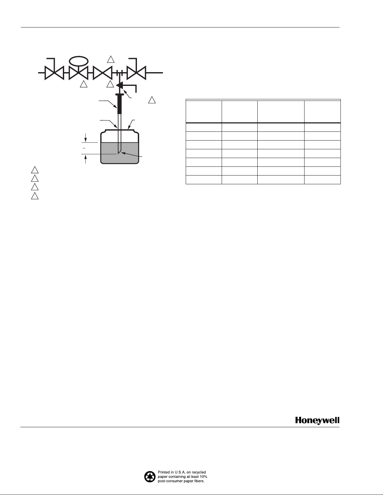
M9547F
Fig. 16. Valve leak test.
1. De-energize the control system to assure that there is
no power to the safety shutoff valve (C) shown in Fig. 7.
2. Close the upstream manual gas cock (A).
3. Make sure the manual test petcock (F) is closed in the
leak test tap assembly (D).
4. Remove the leak test tap plug and connect the test
apparatus to the Leak Tap (D).
5. Close the downstream manual gas cock (E).
6. Open the upstream manual gas cock (A).
7. Run the safety shutoff valve (C) to its fully open position
(through the safety system); then immediately
de-energize the system to close the valve.
8. Immerse a 1/4 in. tube vertically 1/2 in. (12.7 mm) into
a jar of water.
9. Slowly open the test petcock (F).
10. When the rate of bubbles coming through the water
stabilizes, count the number of bubbles appearing
during a ten-second period. Each bubble appearing
during a ten-second period represents a flow rate of
approximately 0.001 cfh.
To meet U.S. requirements, leakage must not exceed the
values listed in Table 5.
Table 5. Allowable Leakage for V48/V88 Valves.
V48/V88
Pipe Size
(in.) Air (cc/h)
Natural Gas (
a
cc/h)
Bubbles/10
sec.; Max @
45 degrees
3/4 266 332.5 8
1 302 377.5 9
1-1/4 442 552.5 13
1-1/2 442 552.5 13
2 650 812.5 20
2-1/2 650 812.5 20
3 650 812.5 20
a
Natural gas: multiply air by 1.25.
b
Bubble leakage: Divide natural gas by 573, then multiply by
14.
NOTE: For international leak test requirements, contact
the office of the appropriate approval agency.
After the test:
11. Close the upstream manual gas cock (A).
12. Close the test petcock (F), remove the test apparatus,
and replace the leak test tap plug (D).
13. Open the upstream manual gas cock (A) and energize
the safety shutoff valve (C).
14. Test with soap bubbles to assure that there is no leak
at the test tap (D).
15. De-energize the safety shutoff valve (C).
16. Open the downstream manual gas cock (E).
17. Restore the system to normal operation. If two safety
shutoff valves are utilized, each V48/V88 valve is to be
checked for tightness of closure.
b
Automation and Control Solutions
Honeywell International Inc. Honeywell Limited-Honeywell Limitée
1985 Douglas Drive North 35 Dynamic Drive
Golden Valley, MN 55422 Scarborough, Ontario
M1V 4Z9
60-2080—9 G.R. Rev.09-02 www.honeywell.com
 Loading...